Article

Fire Performance of Ventilated Rendered Facades with EPS Insulation: Full-Scale DIN-Type Evaluation and Influence of Cavities on Flame Spread


by
Aušra Stankiuvienė
* and
Ritoldas Šukys
Building Materials and Fire Safety Department, Faculty of Civil Engineering, Vilnius Gediminas Technical University (VILNIUS TECH), Saulėtekio al. 11, LT-10223 Vilnius, Lithuania
*
Author to whom correspondence should be addressed.
Fire 2026, 9(3), 113; https://doi.org/10.3390/fire9030113
Submission received: 29 January 2026 / Revised: 22 February 2026 / Accepted: 27 February 2026 / Published: 3 March 2026
(This article belongs to the Special Issue Behavior of Structural Building Materials in Fire)

Abstract

The fire performance of ventilated facade systems incorporating combustible insulation remains a critical issue in contemporary building design. This study presents a full-scale natural-fire test of a ventilated, rendered facade system containing 150 mm expanded polystyrene (EPS) insulation, conducted in accordance with the DIN 4102-20 methodology. Temperature measurements were recorded at key facade locations via K-type thermocouples, and flame spread, materials melting, and degradation were documented through visual observations. The combustion chamber reached a peak temperature of 912 °C, while the thermocouple located above the opening recorded a maximum temperature of 786 °C. No sustained flaming or debris above the 3.5 m height limit was observed, yet significant internal EPS melting occurred throughout the cavity. These findings underscore the potency of the “chimney effect” in ventilated cavities, highlight the limitations of the current acceptance criteria, and provide evidence relevant to ongoing efforts to develop more coherent approaches to facade fire-safety assessment.

1. Introduction

Modern building envelopes increasingly adopt ventilated facade systems, which integrate an outer cladding layer fixed to a substructure and separated from the insulation/substrate by an air cavity [1,2,3]. While such assemblies enhance hygro-thermal performance, energy efficiency, and aesthetic flexibility, they also pose specific fire-safety challenges. Among these, the upward buoyant flow of hot gases and flames through the cavity—commonly termed the “chimney effect”—can dramatically accelerate vertical fire spread, beyond what would occur in solid-wall constructions [4,5,6,7].
Notably, major fire incidents such as the Grenfell Tower fire in 2017 in London, UK [8], and the Lacrosse fire in Melbourne, Australia [9], exposed how combustible insulation and inadequately compromised cavity barriers enabled rapid flame propagation across many storeys. These events reinforced the regulatory focus on facade fire performance and accelerated the development of large-scale test methods.
Expanded polystyrene (EPS) remains widely used in external thermal insulation composite systems (ETICS) due to its favourable thermal resistance and cost-efficiency [10]. Nevertheless, EPS is a thermoplastic material with inherent flammability, typically classified as E under EN 13501-1 [11]. EPS begins to soften near 100 °C, melts around 240 °C, and when ignited, releases combustible styrene gases [12,13]. When placed behind a ventilated cladding, the heat flux and convective flow within the cavity can surpass the insulation’s tolerance, leading to melting, dripping and vertical spread [4,5,14,15,16,17].
Large-scale test methods have been developed to assess facade system fire performance rather than simply material classification. These include DIN 4102-20 (Germany) [18], BS 8414-1/BS 8414-2 (UK) [19], ISO 13785-2 (International) [20], SP Fire 105 (Sweden) [21], and NFPA 285 (USA) [22]. While harmonisation efforts continue in Europe (e.g., the “European Approach to Assess the Fire Performance of Facades” initiative) [23], significant differences in geometry, fuel, instrumentation and acceptance criteria persist [24,25,26,27].
This paper reports a full-scale real-fire experiment conducted on a ventilated rendered facade system with 150 mm EPS 70 insulation in Lithuania. The objective is to present detailed thermal and visual results, evaluate compliance with DIN 4102-20 [18] criteria, analyse the role of cavity geometry and insulation behaviour, and derive design and regulatory implications.

2. Literature Review and Problem Statement

The development of fire-resistant facade systems is crucial for minimising fire damage and ensuring the durability of modern buildings. Contemporary facade assemblies not only impact aesthetics and energy efficiency but also significantly influence the fire performance of the building envelope. Different facade systems respond differently to fire, with their behaviour determined by the materials used, their geometric arrangement, and the presence of cavities or ventilation layers. These factors collectively determine how fire can spread, whether externally or within concealed spaces, ultimately affecting the building’s overall safety.
Within this context, fire behaviour in ventilated facade cavities has emerged as a major area of concern. Ventilated facades containing an air gap enable channelised vertical movement of flames and hot combustion gases, allowing rapid upward acceleration while entraining fresh air at the cavity base [22]. Experimental studies and computational fluid dynamics (CFD) models demonstrate that even narrow cavities of 25–50 mm can generate gas velocities exceeding 5 m s−1, levels sufficient to sustain continuous flame spread under a variety of thermal exposures [5,15,28]. Such accelerated flow intensifies convective heat transfer, increases thermal loading on upper facade regions, and promotes flame impingement on insulation or substrate layers [16,28]. This chimney effect has been shown to increase fire growth rates by three to six times compared with non-ventilated configurations, amplifying thermal degradation and facilitating concealed flame progression [16,28]. These risks are heightened in assemblies incorporating combustible components, where airflow can support pyrolysis, molten polymer migration, and hidden ignition.
Expanded polystyrene (EPS) insulation, widely valued for its thermal performance and cost efficiency, presents multiple vulnerabilities when exposed to fire. In external thermal insulation composite systems (ETICS), such degradation results in melting, recession from the heat source, and release of molten polymer, which may drip or migrate into ventilated cavities and potentially contribute to secondary ignition. Despite extensive research on EPS in traditional ETICS with solid renders, comparatively few studies examine its behaviour behind ventilated cladding, where airflow, cavity geometry, and pressure variations may significantly alter degradation pathways.
International full-scale testing methods have been developed to evaluate the fire behaviour of facade systems, though these differ substantially in exposure severity, repeatability, and diagnostic capability. The DIN 4102-20 [18] method simulates a room-corner fire by igniting a timber crib within a combustion chamber that vents flames onto a full-scale facade specimen. Acceptance criteria require the absence of sustained flaming or debris above 3.5 m, surface temperatures not exceeding 500 °C at that height, and no internal flaming at the specimen’s upper edge. BS 8414 [19] employs a larger test rig and includes explicit measurement of external flame-spread height, whereas ISO 13785-2 [20] uses a calibrated propane burner to enhance reproducibility. Comparative studies indicate that ISO burners offer improved consistency, while wood-crib methods such as DIN 4102-20 [18] more closely mimic the fluctuating heat release typical of real compartment fires. A recurring critique is that reliance on external criteria—such as visible flame height or surface temperature—may fail to detect internal cavity damage, especially when combustible insulation is concealed behind cladding layers. This limitation can lead to an underestimation of fire hazards associated with hidden pyrolysis, smouldering, or confined flame spread.
Research conducted over the past five decades has introduced a variety of small-scale and large-scale methods considered suitable for assessing the flammability of facade systems. Comprehensive flammability testing is essential to understand fire behaviour and effectively mitigate associated risks fully. This approach was applied in study [29], which presents results obtained from empirical investigations carried out under controlled conditions, providing valuable insights into the fire performance of materials used in facade systems. The experiments focused on evaluating the influence of graphite-modified EPS foam on the flammability of the facade system. The findings demonstrated that fire spread within facade systems depends on the heating source, the flammability characteristics of the facade finishing materials, and the correctness of system installation.
To ensure the suitability of polystyrene insulation, flammability testing at multiple scales is required. Studies described in [30,31] investigated facade systems incorporating thermoplastic expanded polystyrene (EPS) of various thicknesses through flammability tests conducted at different scales. The results indicated that the outer facade layer is the first to be damaged, significantly influencing flame spread. Sample orientation was also identified as an important factor, as EPS may melt and flow during heating, thereby affecting the burning rate of the molten material. Furthermore, masonry coatings were found to restrict the flow of molten EPS, while non-combustible stone wool barriers effectively reduced the vertical flame propagation rate. However, these studies did not account for the combustibility classification of the materials used in the facade systems.
Additionally, study [32] examined facade systems incorporating both combustible and non-combustible insulation materials. The results indicated that the flammability of the outer facade layer has a significant effect on the overall fire performance of the wall system. It was noted that the flammability of insulation materials becomes crucial only after the outer facade layer is damaged. Consequently, damage to the external layer may lead to fire propagation due to the presence of combustible materials in the inner layers. However, the flammability properties of the outer facade layer itself were not thoroughly analysed. Another study [33] investigated how melt-flowing and melt-dripping behaviours increase fire hazards in external wall systems. This research focused on expanded polystyrene (EPS), a commonly used thermoplastic insulation material in facade applications. The experiments analysed flame spread in EPS foam to enhance exterior fire safety; however, a detailed assessment of EPS flammability properties was not provided.
Numerous researchers have employed numerical simulations to evaluate the fire performance of facade systems using different standard fire resistance tests. Although several large-scale facade fire test standards have been developed worldwide, they vary significantly between countries, making direct comparison of test results difficult. In study [34], five scenario-based facade fire standards—BS 8414-1 (UK), GB/T 29416 (China), ISO 13785-2, NFPA 285 (USA), and JIS A 1310 (Japan)—were simulated. The simulations analysed heat flux and temperature within the facade fire plume, which govern ignition and flame propagation along the facade. While equivalent fire scenarios were compared across different standards, the results remain purely numerical and mainly serve to support the future improvement and optimisation of facade fire testing methods.
In a further study [35], fire exposure and temperature conditions were simulated using three standard fire tests. The conclusions highlighted the need for a unified facade fire testing standard in Europe. Additionally, flame propagation from facade openings was investigated using five different standardised methods. The simulations focused on heat flux and temperature distributions along the facade fire flow, both of which significantly influence flame spread. The results varied depending on the testing method applied, leading to differences in flammability parameters and emphasising the need for experimental flammability studies under real fire conditions, as well as further development and optimisation of facade fire testing procedures. Although fire modelling is a valuable tool for analysing different facade fire scenarios, its application to real-world situations remains limited due to variations in material properties, facade system configurations, and installation practices.
Therefore, it is essential to conduct flammability tests on facade systems under real fire conditions, using EPS with well-defined flammability characteristics and ensuring proper installation of the facade system.
Despite the range of available test methods, publicly accessible data for rendered, ventilated facade systems containing EPS insulation remain limited. Most published work focuses on ETICS without ventilation cavities, resulting in significant knowledge gaps regarding how cavity geometry, insulation thickness, gap width, and cladding support systems influence internal fire development. This raises a critical practical question for designers, regulators, and fire-safety engineers: Does compliance with externally observable test criteria ensure internal safety when combustible materials are installed within a ventilated facade cavity? The present study addresses this gap by providing full-scale experimental data accompanied by detailed internal temperature, heat-flux, and damage-mapping analyses for a ventilated rendered facade incorporating EPS insulation.

3. Materials and Methods

The facade test followed the methodology set out in the DIN 4102-20 [18] standard developed by the German Standardisation Institute for evaluating the reaction-to-fire of building facades when exposed to flames emerging from an opening. This method uses a combustion chamber with a timber fuel load (wood crib) to create a realistic interior fire that vents through an opening and impinges on the facade assembly. Temperature evolution, flame propagation, and physical damage were recorded, and acceptance criteria include limitations on external and internal flame spread, falling debris, and specified temperature thresholds at 3.5 m above the opening. The test duration was 30 min of active burning (fuel removed/allowed to self-extinguish thereafter) with further monitoring extended up to 60 min.
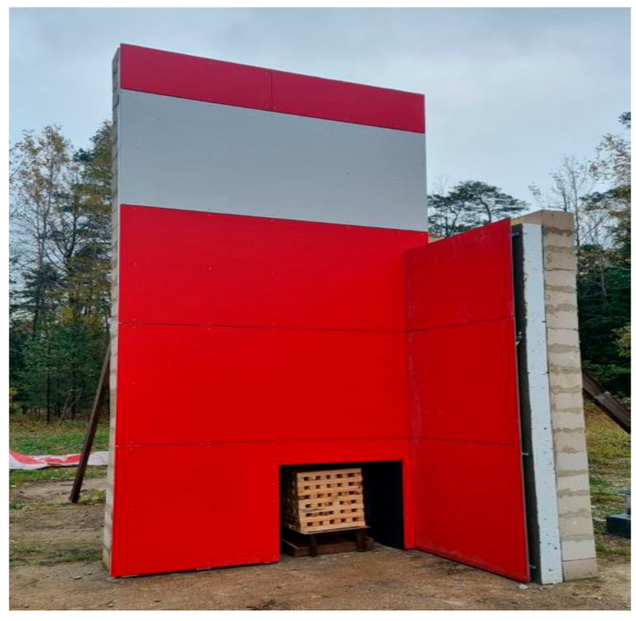
The facade system was constructed on an L-shaped masonry wall to replicate a corner condition. EPS 70 type expanded polystyrene (EPS) insulation boards were used for the tests. The declared reaction-to-fire class of the expanded polystyrene was E (manufacturer: UAB “Šilputa”, Skaidiškės, Vilnius District, Lithuania). Boards with a nominal thickness of 150 mm were installed and bonded to the masonry substrate using the cementitious adhesive mortar “Sakret BAK” (manufacturer: UAB “Sakret LT”, Kėdainiai, Lithuania), which has a declared reaction-to-fire class A1 and a nominal material consumption of 6.0 kg/m2. The EPS boards were reinforced with the same cementitious mortar “Sakret BAK” (reaction-to-fire class A1, nominal consumption 6.0 kg/m2) in combination with a reinforcing mesh “Sakret Armavimo tinklelis” (manufacturer: AS “Valmieras Stikla Šķiedra”, Valmiera, Latvia) with a nominal areal mass of 160 g/m2, forming a reinforced render layer approximately 6 mm thick. A ventilated facade substructure was installed on top of the reinforced EPS layer. The build-up of the facade system (from outside to inside) consisted of fibre-cement cladding panels “Sfibral Grey” (manufacturer: “Eternit Österreich GmbH”, Vöcklabruck, Austria), with an 8 mm thick and with a declared reaction-to-fire class A2-s4, d0, fixed to vertically oriented stainless-steel L-shaped profiles (50 × 50 mm) using blind steel rivets. The steel profiles were connected to steel angle brackets using self-drilling screws, while the angle brackets were anchored to the masonry with M10 steel bolts and nuts. Between the cladding and the insulation layer, a ventilated air cavity with a width of approximately 65–70 mm was provided. Horizontal joints between the cladding panels measured approximately 7 mm. Ventilation of the cavity above the opening was ensured by a 0.5 mm thick perforated steel flashing. The innermost layer of the system was a brick masonry wall. A view of the test specimen before ignition is presented in Figure 1.
A wooden crib of 25 kg spruce timber (stick dimensions: 40 × 40 × 500 mm) was placed inside a combustion chamber. Flames were directed through a 500 × 480 mm opening at the top of the chamber into the facade specimen for 30 min, followed by observation up to 60 min post-ignition. The specimen was conditioned outdoors for at least 14 days after assembly and before testing, ensuring that the conditions matched the actual operating conditions of the facade. At the beginning of the test, before ignition, the ambient temperature was +9.0 °C, the relative humidity was approximately 88%, and a light southerly wind was recorded at about 1.1 m/s. During the test, the meteorological conditions changed only slightly: the temperature decreased by about 1 °C, the relative humidity increased by about 3%, and the wind speed rose by approximately 0.4 m/s. These changes did not significantly impact the test results.
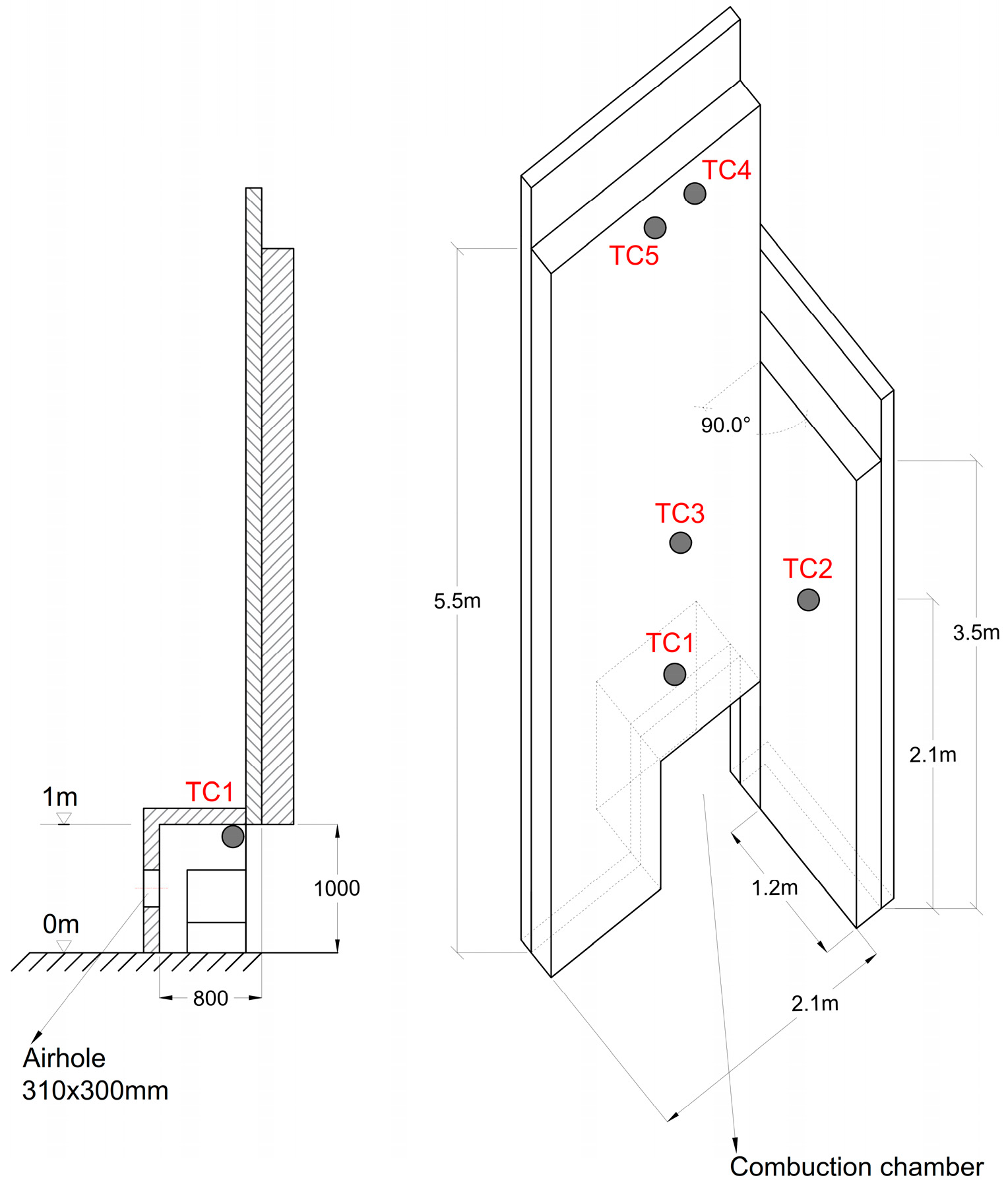
Temperatures were recorded with five K-type thermocouples connected to a Eurotherm 6180A data logger. Thermocouple placement followed DIN 4102-20 [18], and the locations, identification, and positions of the thermocouples in the sample are detailed in Figure 2. The thermocouples were positioned at representative locations to capture the temperature distribution at critical points of the facade system and to assess vertical fire spread and cavity-induced thermal effects. The thermocouple locations were as follows:
-
TC1: inside the combustion chamber at the top edge of the opening;
-
TC2: in the formed wing (2.1 m above ground) to compare cavity/wing response;
-
TC3: embedded beneath the render at 1.1 m above the opening in the main facade (closest external thermocouple to the fire);
-
TC4 and TC5: embedded beneath the render at 3.3–3.5 m above the opening in the main facade.
In addition to thermocouple recordings, the test was video recorded for qualitative observation (flame appearance, panel failure, dripping) and the wall was inspected post-test to assess the extent of EPS degradation. Thermocouple placement and measurement protocol followed DIN 4102-20 [18] recommendations. Visual recording systems captured flame spread, material deformation and debris. Post-test, cladding and render were removed to inspect EPS degradation.

4. Results

4.1. Qualitative Observations

The qualitative development of the fire test was assessed based on visual observation recorded during the experiment. A summary of the main observations and the corresponding time-stamped events is presented in Table 1, which provides a chronological description of the significant phenomena observed during the test.
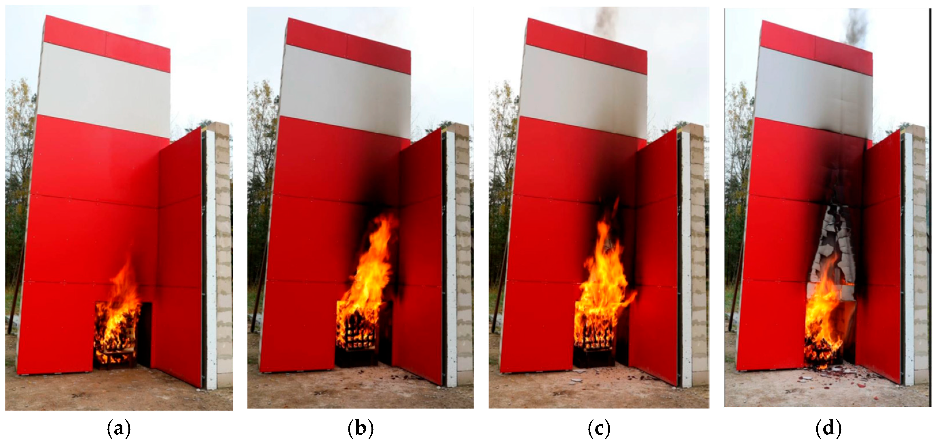
As shown in Table 1, flame propagation and EPS melting were observed during the early stages of the test, followed by vertical fire spread within the cavity. These phenomena represent the main stages of fire development and are illustrated by representative photographs of the experimental process presented in Figure 3.

4.2. Temperature Development

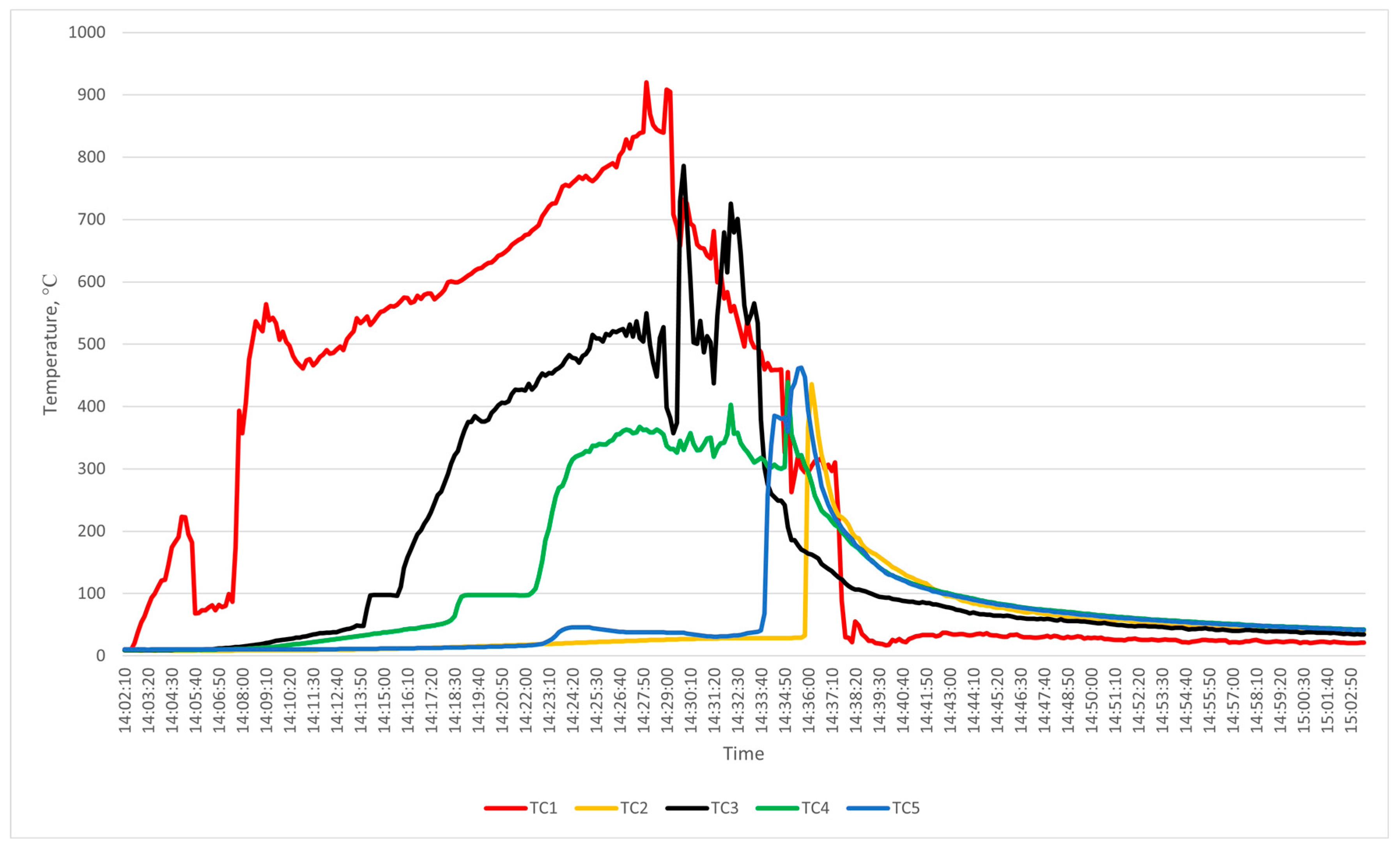
The curve of sample temperatures over time is shown in Figure 4. Recorded peak temperatures (selected thermocouples) and timing:
  • TC1 (combustion chamber, reference): Tmax = 912 °C;
  • TC2 (wing at 2.1 m): recorded lower peak temperatures compared to TC3 (consistent with distance from the source) ~150 °C less;
  • TC3 (1.1 m above the opening, closest external thermocouple under render): Tmax = 786 °C recorded at ~27 min after ignition;
  • TC4 and TC5 (3.3–3.5 m above opening): temperatures measured did not exceed 500 °C (i.e., remained below the specified limit at 3.5 m).
The rapid increase in temperature recorded at TC3, in contrast to the higher-positioned thermocouples, indicates localised heat concentration near the opening. Additionally, there is restricted upward thermal penetration beyond approximately 1.5 m. The observed temperature levels align with previously reported facade fire test results, where peak temperatures ranging from 700 °C to 900 °C were measured within flame impingement zones.

4.3. Physical Damage Assessment

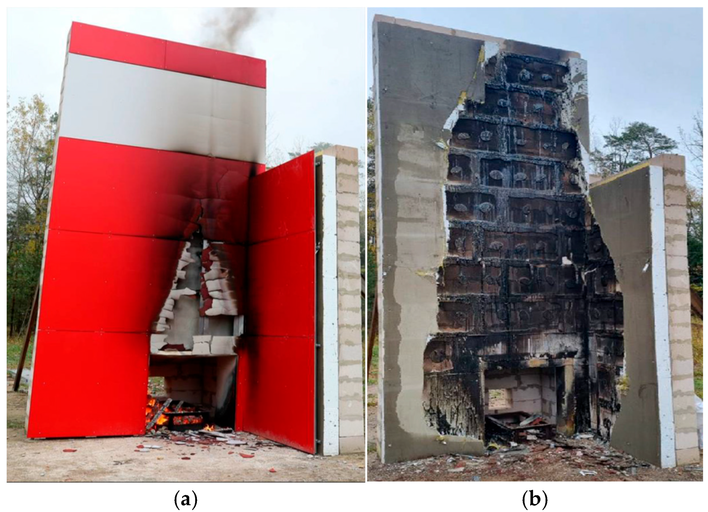
The flame spread, and structural changes in the facade system after testing are shown in Figure 5.
Following the DIN 4102-20 [18] test and subsequent removal of the external cladding and reinforced render in the impacted area, the damage to the expanded polystyrene (EPS) insulation was assessed. In the main facade region, the vertical penetration of EPS degradation reached up to 241.0 cm above ground level, representing the maximum vertical extent of EPS melting or thermal compromise as defined in the DIN 4102-20 [18] post-test inspection procedure. The horizontal spread of EPS damage in the wide facade area extended up to 140.0 cm measured from the centreline of the opening. In the narrow wing section, the vertical extent of EPS damage was approximately 357.0 cm, while the horizontal spread in this region reached up to 99.0 cm, measured from the main facade.

4.4. Compliance Evaluation

The acceptance criteria derived from DIN 4102-20 [18] were:
  • No sustained flaming or flaming debris above 3.5 m height for more than 30 s;
  • Surface and internal temperatures at 3.5 m must not exceed 500 °C;
  • No internal flaming or material disintegration above the top of the specimen;
  • Falling flaming particles must cease within 90 s of fuel removal.
Assessment criteria and compliance results were established in accordance with the standard’s provisions and are provided in Table 2.
In conclusion, although external criteria have been fulfilled, the internal cavity component fails to achieve the intended safety objective due to significant damage to the expanded polystyrene (EPS).

5. Discussion

5.1. Cavity Fire Dynamics and Chimney Effect

The elevated temperature recorded at TC3 (~786 °C) indicates severe local thermal exposure within the ventilated cavity and confirms the presence of intensified heat transfer processes governing fire development in the facade system. The results suggest that the cavity acted as an effective vertical flow channel. The observed fire spread behaviour demonstrates the presence of a pronounced chimney effect within the ventilated rendered facade system. The cavity facilitated the vertical transport of hot gases, resulting in increased thermal exposure and promoting upward flame spread along the facade assembly. This mechanism significantly influenced the fire performance of the system by intensifying heat transfer to combustible components and increasing the likelihood of insulation failure.
The intensity of the chimney effect is known to depend on several governing parameters, including cavity geometry, cavity depth, and ventilation opening conditions, which control airflow velocity, temperature distribution, and heat transfer rates within the cavity. Previous experimental and numerical studies [4,5,6,7,8,9,30,31,32] have shown that narrow cavities and restricted ventilation openings may further accelerate upward flow, leading to higher flame spread rates and increased thermal exposure of façade materials. The elevated temperatures observed in the present full-scale DIN-type test are consistent with these findings and highlight the importance of cavity configuration in determining facade fire behaviour.
Although the present investigation considered a single cavity configuration, the results emphasise the critical role of cavity-induced flow in governing fire dynamics in ventilated rendered façade systems with EPS insulation. The findings demonstrate that chimney-driven fire spread may substantially increase the risk of insulation degradation even where non-combustible external cladding is used. A detailed quantitative analysis of flow behaviour and heat transfer under varying cavity geometries was beyond the scope of this study and remains an important area for further research.

5.2. EPS Behaviour Under Elevated Exposure

The EPS softened and melted rapidly under combined convective and radiative heat exposure, with melting initiating at approximately 15 min and producing burning molten droplets, consistent with known EPS failure modes under high heat flux and convective fire exposure [4,8,13,14]. Thermal degradation of EPS, including softening, shrinkage, and melting, promotes flame spread through burning drips and the exposure of additional combustible surfaces.
In ventilated facade systems, EPS degradation leads to the opening of the cavity and widening of the ventilation gap, which enhances airflow upward and increases the oxygen supply to the combustion zone. This creates a feedback mechanism that intensifies fire growth and vertical flame spread, consistent with the two-stage degradation model reported in previous studies [26,27,28]. The upward movement of hot gases within the cavity is associated with the chimney effect, which increases convective heat transfer and accelerates fire development [27].
By contrast, non-ventilated facade systems without cavities do not provide a continuous airflow path, limiting buoyancy-driven flow and reducing chimney-driven heat transfer. Consequently, flame spread is typically less pronounced, and fire development occurs at a slower rate. Experimental and numerical studies have shown that cavity geometry and fire-driven flow significantly influence heat transfer and flame propagation in facade systems [26,27,28]. These mechanisms provide a physical explanation of how the presence of a ventilated cavity may intensify fire development compared with non-ventilated configurations.

5.3. Implications Relative to Current Test Criteria

Although the specimen passed DIN 4102-20 [18] external criteria, the observed internal EPS damage suggests that compliance with externally based performance limits does not guarantee safety from internal degradation pathways in a ventilated facade system. This observation aligns with critiques that externally measured parameters (such as flame height, surface temperature) may not adequately capture the failure mechanisms associated with internal cavity fire dynamics, including insulation degradation and heat transfer within the ventilated cavity. This observation aligns with previous studies showing that externally measured performance indicators may not fully represent internal system behaviour or cavity fire propagation mechanisms [24,25,26,35,36]. A comparison with other large-scale facade fire test methods provides additional context for interpreting these findings. Standards such as BS 8414 [19], NFPA 285 [22] and ISO 13785 [20] assess the fire performance of a facade using different fire exposure conditions, measurement strategies and evaluation criteria. Table 3 summarises the main differences between the selected large-scale facade fire test standards relevant to interpreting these results.
While all methods evaluate vertical fire spread, their treatment of internal system response and cavity behaviour differs significantly. The observed internal EPS degradation, despite compliance with DIN 4102-20 [18] external criteria, suggests that performance outcomes may vary under evaluation frameworks that explicitly consider internal system response and cavity fire propagation.
These findings support previous critiques that externally measured performance indicators alone may not fully represent the fire behaviour of ventilated facade systems containing combustible components. Consequently, facade fire testing and regulatory frameworks should consider internal cavity behaviour and degradation mechanisms in addition to external flame spread metrics.

5.4. Design and Regulatory Implications

The selection of the EPS insulation thickness and cavity depth in the present study was based on regulatory and technical requirements applicable to ventilated facade systems and representative of current European construction practice. In accordance with national building regulations reflecting European regulatory frameworks (e.g., STR 2.04.01:2018, Lithuania [37]), facade systems used in building design and construction are required to satisfy defined performance requirements related to fire behaviour, thermal insulation properties, and installation conditions. Consequently, the tested configuration represents facade system parameters commonly applied in practical building applications rather than an arbitrary experimental arrangement.
From a design and regulatory viewpoint, the present findings suggest the following implications:
  • The use of combustible insulation (e.g., EPS) in ventilated cavities should be avoided or strictly limited for buildings above certain heights due to the increased risk of chimney-driven flame spread [19,23,38];
  • The provision of cavity barriers or fire-stop systems is essential to interrupt buoyancy-driven flow within the cavity and mitigate vertical fire propagation [39,40];
  • Facade fire testing approaches should prioritise system-level performance, including cavity behaviour, and interaction between components, rather than relying solely on material reaction-to-fire classification [20,41,42];
  • Post-installation inspections and quality control, particularly regarding cavity continuity, correct installation of fire barriers, insulation condition and cladding fixings, are critical to ensure that the as-built performance corresponds to the tested facade configuration [39,43].

5.5. Limitations of the Study

The present test covers a single full-scale specimen under one facade configuration; therefore, variability associated with cavity width, vent sizing, insulation type, or panel fixings was not systematically evaluated. Thermocouple instrumentation was limited in spatial density, and the inclusion of additional measurement techniques, such as heat-flux sensors or optical pyrometry, would provide improved insight into local heat transfer processes and flame–surface interactions within the cavity.
Measurement uncertainty must also be considered when interpreting the reported temperature values. Although a formal uncertainty propagation analysis was not performed, the combined measurement uncertainty can be reasonably estimated from thermocouple accuracy specifications, together with potential influences from radiative heat exchange, local airflow effects, and sensor positioning variability within the ventilated cavity. Temperature measurements obtained using thermocouples in fire environments are known to be affected by thermal disturbances caused by probe insertion, radiative heat exchange, and heat transfer effects that may introduce systematic deviations from true temperatures. Experimental and modelling studies have shown that thermocouple measurements under fire conditions can have significant deviations due to combined radiative and convective heat transfer processes [43,44]. Improvements in thermocouple shielding and probe design have been shown to reduce such deviations, although measurement differences of several percent may still occur depending on fire exposure conditions [45]. Under the present experimental conditions, the uncertainty in peak temperature measurements is expected to remain within approximately ±10–15%. This level of uncertainty does not affect the robustness of the observed thermal response trends or the interpretation of the chimney-driven heat transfer and fire dynamics governing cavity behaviour.
Furthermore, the repeatability of full-scale facade fire tests is inherently limited due to variability in ignition conditions, environmental exposure, installation tolerances, and material heterogeneity, which may influence the generalisation of results to broader applications. Recent studies have demonstrated that facade fire behaviour is strongly influenced by fire exposure characteristics, heat release rate, and boundary conditions, leading to variability in heat flux and temperature distribution across different test configurations [46]. Probabilistic and parametric investigations have further highlighted the sensitivity of facade fire behaviour to system geometry and cavity characteristics, supporting the need for systematic evaluation of experimental variability and uncertainty in facade fire assessment [47].
Additionally, ambient and installation conditions in the present test (e.g., +9.8 °C start, outdoor conditioning) may differ from real building situations. Future work should extend testing regimes to multiple variants, include cavity instrumentation, and integrate CFD modelling for parametric sensitivity analyses.

5.6. Opportunities for Future Research

Future research should extend testing to include multiple facade configurations and incorporate controlled-rate parametric studies that examine cavity geometry, ventilation characteristics and alternative insulation systems (e.g., mineral wool or hybrid solutions) to quantify their impact on flame spread and heat transfer. Such case studies would allow a systematic assessment of the sensitivity of cavity fire behaviour to key design parameters and support generalisation beyond the single configuration considered in this study.
Coupling experimental investigations with computational fluid dynamics (CFD) modelling would further strengthen the interpretation of the observed phenomena. Validated numerical simulations could resolve airflow velocity profiles, temperature gradients, heat flux distribution, and pressure differentials within the ventilated cavity, thereby improving understanding of chimney-driven fire dynamics. Model validation against experimental measurements would enable extrapolation to alternative facade geometries, boundary conditions, and material configurations, supporting performance-based facade fire safety design.
Emerging studies (2023–2025) explore hybrid insulation systems (combining EPS and mineral wool), AI-assisted fire video analysis for facade fires, and integrated CFD-FEM modelling of facade system fire behaviour [10,48,49,50,51,52]. Extending these approaches to ventilated facades with combustible insulation may contribute to the development of predictive fire-safety frameworks and inform future design guidance and regulatory codification.

6. Conclusions

The full-scale real-fire test of a ventilated rendered facade with 150 mm EPS insulation under DIN 4102-20 [18] conditions revealed that:
  • Maximum measured surface temperature at 1.1 m above the opening was ~786 °C; the chamber peak reached ~912 °C.
  • No external sustained flaming or debris above 3.5 m occurred; surface temperatures at 3.5 m remained below 500 °C.
  • Significant internal EPS melting and cavity involvement occurred, representing a failure mode not captured by standard external criteria.
  • The ventilated cavity produced a chimney effect that accelerated the degradation of combustible insulation despite non-combustible cladding.
  • For facade fire safety, non-combustible insulation within ventilated cavities is strongly recommended; cavity barriers and system-level testing are critical to robust performance.
These findings contribute to the evidence base for harmonised European facade fire assessment and emphasise the need to interpret facade fire criteria in terms of both external flame spread and internal cavity integrity.

Author Contributions

Conceptualisation, A.S. and R.Š.; methodology, A.S.; validation, A.S. and R.Š.; formal analysis, A.S. and R.Š.; data curation, R.Š.; writing—original draft preparation, A.S.; writing—review and editing, R.Š.; visualisation, A.S. All authors have read and agreed to the published version of the manuscript.

Funding

This our research received no external funding.

Institutional Review Board Statement

Not applicable.

Informed Consent Statement

Not applicable.

Data Availability Statement

Data are contained within the article.

Acknowledgments

The authors acknowledge the Polystyrene Foam Association (Vilnius, Lithuania) and the Fire Research Centre (Vilnius, Lithuania) for their long-term collaboration with VILNIUS TECH.

Conflicts of Interest

The authors declare no conflicts of interest.

References

  1. Ibáñez-Puy, M.; Vidaurre-Arbizu, M.; Sacristán-Fernández, J.A.; Martín-Gómez, C. Opaque Ventilated Façades: Thermal and energy performance review. Renew. Sustain. Energy Rev. 2017, 79, 180–191. [Google Scholar] [CrossRef]
  2. De Masi, R.F.; Ruggiero, S.; Vanoli, G.P. Hygro-thermal performance of an opaque ventilated façade with recycled materials during wintertime. Energy Build. 2021, 245, 110994. [Google Scholar] [CrossRef]
  3. Nghana, B.; Tariku, F.; Bitsuamlak, G. Assessing ventilation cavity design impact on the energy performance of rainscreen wall assemblies: A CFD study. Build. Environ. 2021, 196, 107789. [Google Scholar] [CrossRef]
  4. Sharma, A.; Mishra, K.B. Experimental investigations on the influence of ‘chimney-effect’ on fire response of rainscreen façades in high-rise buildings. J. Build. Eng. 2021, 44, 103257. [Google Scholar] [CrossRef]
  5. Mendez Alvarez, J.E.; Lange, D.; Hidalgo, J.P.; McLaggan, M.S. Effect of cavity parameters on the fire dynamics of ventilated façades. Fire Saf. J. 2022, 133, 103671. [Google Scholar] [CrossRef]
  6. Peck, G.; Jones, N.; McKenna, S.T.; Glockling, J.L.D.; Harbottle, J.; Stec, A.A.; Hull, T.R. Smoke toxicity of rainscreen façades. J. Hazard. Mater. 2021, 403, 123694. [Google Scholar] [CrossRef]
  7. Jones, N.; Peck, G.; McKenna, S.T.; Glockling, J.L.D.; Harbottle, J.; Stec, A.A.; Hull, T.R. Burning behaviour of rainscreen façades. J. Hazard. Mater. 2021, 403, 123894. [Google Scholar] [CrossRef]
  8. Guillaume, E.; Dréan, V.; Girardin, B.; Koohkan, M.; Fateh, T. Reconstruction of Grenfell Tower fire. Part 2: A numerical investigation of the fire propagation and behaviour from the initial apartment to the façade. Fire Mater. 2019, 44, 15–34. [Google Scholar] [CrossRef]
  9. Cook, N.; Herath, S.; Kerr, S.-M. Suburban densification: Unpacking the misalignment between resident demand and investor-driven supply of multi-unit housing in Sydney, Australia. Aust. Plan. 2023, 59, 26–38. [Google Scholar] [CrossRef]
  10. Zhou, B.; Yoshioka, H.; Noguchi, T.; Wang, K.; Huang, X. Fire Performance of EPS ETICS Facade: Effect of Test Scale and Masonry Cover. Fire Technol. 2021, 59, 95–116. [Google Scholar] [CrossRef]
  11. EN 13501-1:2018; Fire Classification of Construction Products and Building Elements. CEN: Brussels, Belgium, 2018.
  12. Sopikova, E.; Klezla, J.; Kucera, P. Fire Spread Through External Walls of Wooden Materials in Multi-Story Buildings—Part I. Fire 2025, 8, 399. [Google Scholar] [CrossRef]
  13. Nguyen, K.T.Q.; Weerasinghe, P.; Mendis, P.; Ngo, T. Performance of modern building façades in fire: A comprehensive review. Electron. J. Struct. Eng. 2016, 16, 69–87. [Google Scholar] [CrossRef]
  14. McKenna, S.T.; Jones, N.; Peck, G.; Dickens, K.; Pawelec, W.; Oradei, S.; Harris, S.; Stec, A.A.; Hull, T.R. Fire behaviour of modern façade materials—Understanding the Grenfell Tower fire. J. Hazard. Mater. 2019, 368, 115–123. [Google Scholar] [CrossRef]
  15. Livkiss, K.; Svensson, S.; Husted, B.; van Hees, P. Flame Heights and Heat Transfer in Façade System Ventilation Cavities. Fire Technol. 2018, 54, 689–713. [Google Scholar] [CrossRef]
  16. Godakandage, R.; Weerasinghe, P.; Gamage, K.; Adnan, H.; Nguyen, K. A Systematic Review on Cavity Fires in Buildings: Flame Spread Characteristics, Fire Risks, and Safety Measures. Fire 2024, 7, 12. [Google Scholar] [CrossRef]
  17. Tang, M.; Bourbigot, S.; Rogaume, T.; Bensabath, T.; Batiot, B.; Drean, V. Fire Performance Comparison of Expanded Polystyrene External Thermal Insulation Composites Systems and Expandable Graphite-Modified Surface Covers at Different Scales. Fire 2025, 8, 45. [Google Scholar] [CrossRef]
  18. DIN 4102-20:2004; Reaction to Fire Tests for Building Materials and Elements—Part 20: Additional Test for External Wall Cladding. DIN: Berlin, Germany, 2004.
  19. BS 8414-1:2020; Fire Performance of External Cladding Systems. BSI: London, UK, 2020.
  20. ISO 13785-2:2002; Reaction to Fire Tests for Facades—Part 2. ISO: Geneva, Switzerland, 2002.
  21. SP Fire 105:2014; External Wall Fire Test Method. RISE: Borås, Sweden, 2014.
  22. NFPA 285:2019; Standard Fire Test Method for Evaluation of Exterior Wall Assemblies. NFPA: Quincy, ME, USA, 2019.
  23. European Commission DG GROW. European Approach to Assess the Fire Performance of Facades; European Commission: Brussel, Belgium, 2018. [Google Scholar]
  24. Asimakopoulou, E.K.; Kolaitis, D.I.; Founti, M.A. Performance of a ventilated-façade system under fire conditions: An experimental investigation. Fire Mater. 2020, 44, 776–792. [Google Scholar] [CrossRef]
  25. Zehfuß, J.; Northe, C.; Riese, O. An investigation of the fire behavior of ETICS facades with polystyrene under fire loads of different size and location. Fire Mater. 2018, 42, 508–516. [Google Scholar] [CrossRef]
  26. Šukys, R.; Stankiuvienė, A.; Stas, S.; Skrodenis, S.V.; Tyshchenko, O. Ensuring fire safety: Compliance tests for the use of polystyrene foam in facades systems. East.-Eur. J. Enterp. Technol. 2024, 3, 33–41. [Google Scholar] [CrossRef]
  27. Livkiss, K.; Husted, B.P.; Beji, T.; van Hees, P. Numerical study of a fire-driven flow in a narrow cavity. Fire Saf. J. 2019, 108, 102834. [Google Scholar] [CrossRef]
  28. Šukys, R.; Skrodenis, S.V.; Stankiuvienė, A.; Ignatavičius, Č. The Fire Impact Assessment of Facade System. Materialy XII Mizhnarodnoi Naukovo-Praktychnoi Konferentsiyi «Teoriya i Praktyka Hasinnia Pozhezh ta Likvidatsiyi Nadzvychainykh Sytuatsiy». Cherkasy: ChIPB im. Heroiv Chornobylia NUTsZ Ukrainy. 2022, pp. 198–202. Available online: https://nuczu.edu.ua/images/topmenu/science/konferentsii/2022/6.pdf (accessed on 18 December 2025).
  29. Zhou, B.; Yoshioka, H.; Noguchi, T.; Ando, T. Experimental study of expanded polystyrene (EPS) External Thermal Insulation Composite Systems (ETICS) masonery façade reaction-to-fire performance. Therm. Sci. Eng. Prog. 2018, 8, 83–92. [Google Scholar] [CrossRef]
  30. Zhou, B.; Yoshioka, H.; Noguchi, T.; Wang, K.; Huang, X. Upward Fire Spread Rate Over Real-Scale EPS ETICS Façades. Fire Technol. 2021, 57, 2007–2024. [Google Scholar] [CrossRef]
  31. Agarwal, G.; Wang, Y.; Dorofeev, S. Fire performance evaluation of cladding wall assemblies using the 16-ft high parallel panel test method of ANSI/FM 4880. Fire Mater. 2020, 45, 609–623. [Google Scholar] [CrossRef]
  32. Zhang, M.; Wang, Y.; Li, M.; Gou, F.; Sun, J. Experimental investigation of downward discrete flame spread of the thermoplastic material in exterior insulation walls: Melt-flowing and dripping. Fire Saf. J. 2023, 136, 103754. [Google Scholar] [CrossRef]
  33. Li, Y.; Wang, Z.; Huang, X. An exploration of equivalent scenarios for building facade fire standard tests. J. Build. Eng. 2022, 52, 104399. [Google Scholar] [CrossRef]
  34. Anderson, J.; Boström, L.; Jansson McNamee, R.; Milovanović, B. Modeling of fire exposure in facade fire testing. Fire Mater. 2017, 42, 475–483. [Google Scholar] [CrossRef]
  35. McLaggan, M.S.; Hidalgo, J.P.; Carrascal, J.; Heitzmann, M.T.; Osorio, A.F.; Torero, J.L. Flammability trends for a comprehensive array of cladding materials. Fire Saf. J. 2021, 120, 103133. [Google Scholar] [CrossRef]
  36. McLaggan, M.S.; Hidalgo, J.P.; Osorio, A.F.; Heitzmann, M.T.; Carrascal, J.; Lange, D.; Maluk, C.; Torero, J. Towards a better understanding of fire performance assessment of façade systems: Current situation and a proposed new assessment framework. Constr. Build. Mater. 2021, 300, 124301. [Google Scholar] [CrossRef]
  37. STR 2.04.01:2018; Pastatų Atitvaros. Sienos, Stogai, Langai ir Išorinės Įėjimo Durys (Building Enclosures. Walls, Roofs, Windows and External Doors). Ministry of Environment of the Republic of Lithuania: Vilnius, Lithuania, 29 March 2019; Order No. D1-186. Available online: https://www.e-tar.lt/portal/lt/legalAct/1aa5acc055ce11e9975f9c35aedfe438/asr (accessed on 22 January 2026).
  38. Kolaitis, D.I.; Asimakopoulou, E.K.; Founti, M.A. A Full-Scale Fire Test to Investigate the Fire Behaviour of the Ventilated Façade System. In Proceedings of the 14th International Fire and Engineering Conference (Interflam 2016), Windsor, UK, 4–6 July 2016; pp. 1127–1138. Available online: https://pure.ulster.ac.uk/ws/portalfiles/portal/71282186/TB012_KOLAITIS_Colour.pdf (accessed on 26 February 2026).
  39. UK Government. Grenfell Tower Inquiry—Phase 1 Report. In Report of the Public Inquiry into the Fire at Grenfell Tower; UK Government: London, UK, 2019. [Google Scholar]
  40. McKenna, S.T.; Jones, N.; Peck, G.; Dickens, K. Fire spread in ventilated façade cavities: The role of cavity barriers. Fire Mater. 2021, 45, 891–905. [Google Scholar] [CrossRef]
  41. Maluk, C.; Woodrow, M.; Torero, J.L. The potential of integrating fire safety in modern building design. Fire Saf. J. 2017, 88, 104–112. [Google Scholar] [CrossRef]
  42. Lucherini, A.; Adikey, R.; Jomaas, G.; Torero, J.L. Principles for the Fire Performance of External Wall Systems. J. Phys. Conf. Ser. 2025, 3121, 012020. [Google Scholar] [CrossRef]
  43. Pope, I.; Weckman, E.; Torero, J.L. A Correction Method for Thermal Disturbances Induced by Thermocouple Insertion in Fire Experiments; University College London: London, UK, 2020; Available online: https://discovery.ucl.ac.uk/id/eprint/10098755 (accessed on 22 January 2026).
  44. Put, F.; Lucherini, A.; Van Coile, R.; Merci, B. CFD-based analysis of deviations between thermocouple measurements and local gas temperatures during the cooling phase of compartment fires. Fire Saf. J. 2024, 150, 104276. [Google Scholar] [CrossRef]
  45. Han, H.S.; Hwang, C.H. Development and validation of simple-shield thermocouple for fire temperature measurements. J. Fire Sci. 2021, 39, 3–23. [Google Scholar] [CrossRef]
  46. Li, Y.; Zhang, X.; Huang, Z. Exploration of equivalent scenarios for building façade fire tests using numerical simulation. Case Study Therm. Eng. 2022, 36, 102146. [Google Scholar] [CrossRef]
  47. Cheraghi, S.; Behnam, B. Probabilistic assessment of factors influencing façade fire formation and extension. Fire Mater. 2025, 49, 16–49. [Google Scholar] [CrossRef]
  48. Kocianová, A.; Kočí, V.; Maděra, J.; Černý, R. On-site measurement and hygrothermal modelling of degraded ETICS façade systems with EPS insulation and mineral wool fire breaks. Energy Build. 2023, 292, 113162. [Google Scholar] [CrossRef]
  49. Khan, K.; Rasul Islam, R.; Ali, R.; Bernard, H.F. Artificial Intelligence and Data Analytics in Fire Science: Detection, Modeling, and Suppression. Int. J. Appl. Nat. Sci. 2025, 3, 132–141. [Google Scholar] [CrossRef]
  50. Jin, K.; Tian, Z. Effect of Thermal Radiation Heat Transfer on the Temperature Measurement by the Thermocouple in Premixed Laminar Flames. J. Therm. Sci. 2022, 31, 541–551. [Google Scholar] [CrossRef]
  51. Yang, L.; Zhang, H.; Sun, X. Study on fire spread characteristics of high-rise building façades under wind conditions using CFD modelling. Appl. Sci. 2025, 15, 1327. [Google Scholar] [CrossRef]
  52. Yıldız, S.; Arslan, M. Machine learning applications for fire safety in the built environment: Trends, challenges, and future directions. Buildings 2025, 15, 2465. [Google Scholar] [CrossRef]
Figure 1. View of the test specimen before ignition.
Fire 09 00113 g001
Figure 2. Thermocouple placement for the sample.
Fire 09 00113 g002
Figure 3. Representative photographs of the experimental process illustrating the main stages of fire development: (a)—image after 2 min 38 s; (b)—image after 11 min 52 s; (c)—image after 15 min 22 s; (d)—image after 23 min 27 s.
Fire 09 00113 g003
Figure 4. Curves of sample temperature over time.
Fire 09 00113 g004
Figure 5. Image of the sample after the test, breaking off the outer layer: (a)—sample after test; (b)—image of melted EPS.
Fire 09 00113 g005
Table 1. Chronology of major events during the test.
Time
(min:s)
Observation
00:00Ignition of the wood crib
02:38Smoke emission into a ventilated cavity
03:40Cracking of cladding panels
08:21Detached fragments fell to the ground
11:52Flames observed inside the cavity, ascending
15:22Molten EPS drips, burning droplets on the ground
23:27The wood crib collapses, and the flame intensity reduces
30:19Active burning ends, smouldering monitored
60:00Observation period ends, no further flaming
Table 2. Compliance assessment criteria and results.
CriterionLimitObservationOutcome
External flaming
above 3.5 m
NoneNonePass
Surface/internal T
at 3.5 m ≤ 500 °C
≤500 °C<500 °CPass
Continuous flaming
>30 s above 3.5 m
NoneNonePass
Internal EPS integrity
across full height
No melting
above the limit
Full-height
melting
Fail
Falling flaming
droplets > 90 s
NoneStopped < 90 sPass
Table 3. Comparison of selected large-scale facade fire test standards.
AspectDIN 4102-20BS 8414
(Parts 1–2)
NFPA 285ISO 13785-2
Test objectiveFire behaviour of external wall systemsFire spread performance of external cladding systemsFire propagation within wall assembliesLarge-scale facade fire propagation
Fire exposureExternal burner simulating a window fireLarge external crib fire sourceCompartment fire with a window openingExternal fire source at facade base
Main performance criteriaExternal flame spread and surface temperature limitsTemperature limits and vertical fire spread at multiple facade levelsVertical and lateral fire propagation within the wall assemblyFlame spread and heat release behaviour
Internal instrumentationLimitedMultiple thermocouples across facade heights and layersExtensive instrumentation within the wall assemblyVariable depending on configuration
Assessment of cavity behaviourIndirectPartially assessed through temperature criteriaExplicit assessment of internal fire propagationSystem-level facade behaviour
Primary evaluation focusExternal facade responseSystem-level fire spreadInternal wall fire propagationFacade reaction to fire
Disclaimer/Publisher’s Note: The statements, opinions and data contained in all publications are solely those of the individual author(s) and contributor(s) and not of MDPI and/or the editor(s). MDPI and/or the editor(s) disclaim responsibility for any injury to people or property resulting from any ideas, methods, instructions or products referred to in the content.