1. Introduction
Figure 1 presents examples of spherical concrete domes. Their aesthetics and large spans make them attractive structural systems for many applications. The photos show the typical geometrical forms: a spherical cap (partial dome) and a semi-sphere (full dome).
Failure of a concrete dome could happen in either the ring or the meridian direction. Failure in the ring direction transforms the dome into several arches balanced at the apex. In contrast, failure in the meridian direction results in instability, leading to a total collapse. Spherical concrete domes are typically reinforced in the ring direction to prevent hoop brittle tensile failure. In contrast, the meridian direction is usually unreinforced or has minimum reinforcement.
Zingoni and Enoma [
2] presented a closed-form formulation for both meridian and hoop stresses.
Figure 2 shows the typical dome statical system and the developed stresses, where
ϕ is the central angle in the meridian direction,
θ is the central angle in the ring direction,
a is the radius in the meridian direction,
h is the supported hydrostatic head, and
γ is the fluid unit weight.
The stresses in the meridian (
) and ring (
) directions can be evaluated using Equations (1) and (2), considering gravitational loads (
q), and Equations (3) and (4), considering pressure loads.
Equations (3) and (4) can be simplified for the case of constant pressures
P to Equations (5) and (6).
The equations imply that domes subjected to gravitational loads experience compressive meridional stresses along the height. In contrast, hoop stresses change from compression to tension at Φ = 51.8°. However, external pressure always results in compressive stresses in both meridian and hoop directions.
Fire is a significant hazard for domes due to material degradation and thermal displacements. The elevated temperatures of an uncontrolled fire, which experiences flashover, significantly deteriorate the structural elements’ strength and stiffness [
3].
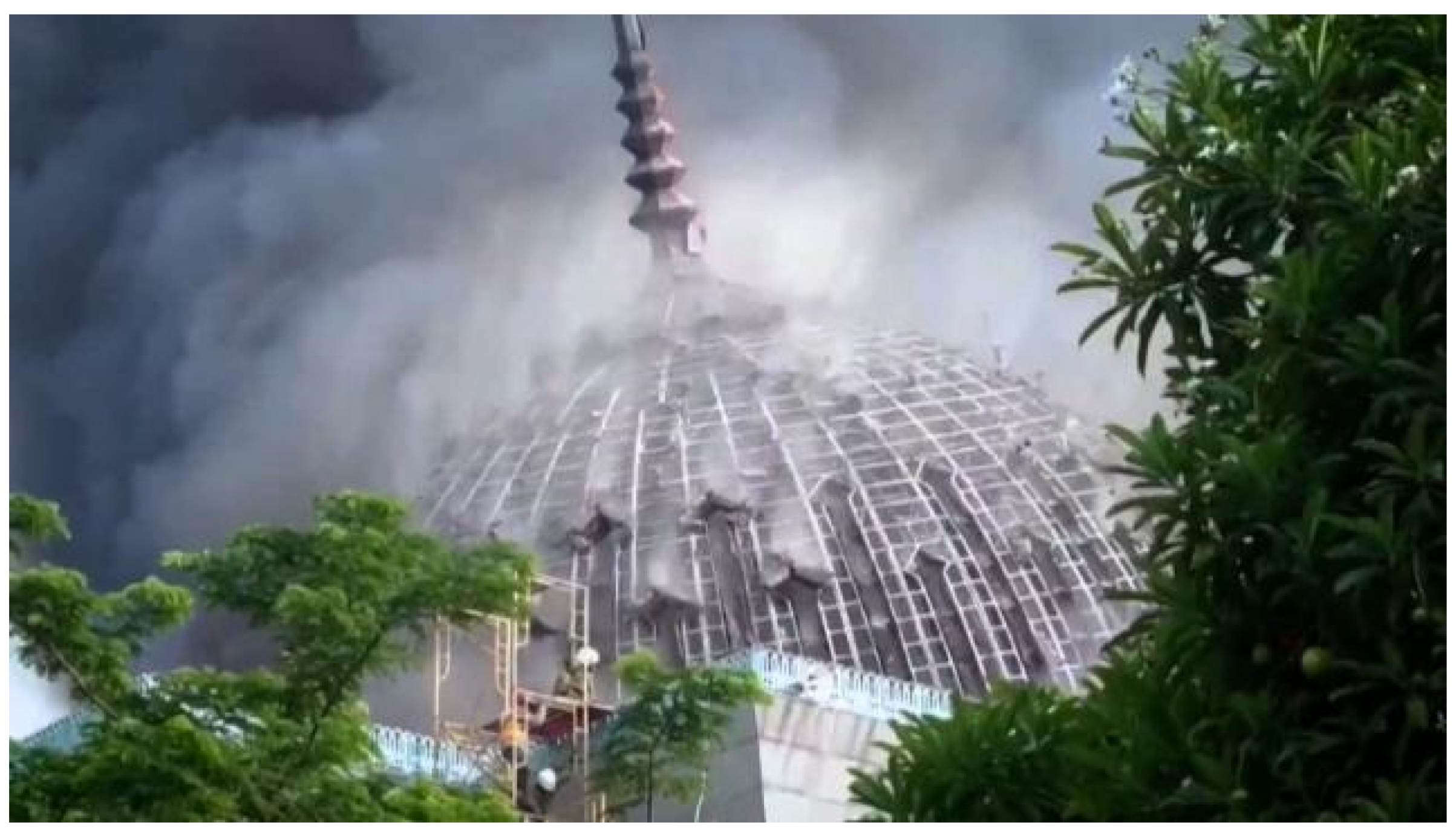
Figure 3 shows that these effects can cause a dome to fail. In a standard fire test, the fire endurance of structural elements is usually expressed in terms of the time to failure. In the case of a realistic fire curve, the endurance can be measured using the equivalent standard fire concept [
4].
The problem of a curved concrete structure subjected to a fire load was introduced in the literature for the case of lined circular concrete tunnels [
6], which have a single curvature. When these tunnels are subjected to fire, the prevailing failure mode is concrete crushing rather than tunnel buckling [
7]. Moreover, structural collapse has been found to take place at temperatures exceeding 1000 °C [
7]. Passive protection is commonly used to increase a tunnel’s fire endurance [
8].
This research aimed to numerically identify the fire endurance of a spherical concrete dome subjected to either superimposed gravitational loads or external pressure during a standard fire incident. The vulnerabilities of the dome’s fire endurance to ring reinforcement, thickness, stiffness, central angle, load type, structural boundary conditions, and load ratio were also assessed.
Figure 4 presents the configuration of the research problem, where either an external pressure or a uniformly distributed gravitational load is applied simultaneously with the fire load for a specific type of structural support. The following sections present details about the modeling process and the parametric study.
2. Modeling and Validation
Thermal and structural analyses were conducted using Abaqus/CAE 2021 [
9]. After examining different modeling techniques, an axisymmetric finite element (FE) model provided good accuracy with reduced computational effort compared to 3D modeling. The model adopted a 4-node deformable CAX4R element [
9] for thermal and structural analysis stages.
The transient thermal analysis problem was solved using the Abaqus transient heat transfer module. Recommendations of the Euro code [
10] were adopted to determine concrete thermal properties, considering normal-weight siliceous concrete. Average values between the upper and lower limits of concrete thermal conductivity were adopted as a function of temperature. Concrete’s specific heat at 0% moisture content was considered as a function of temperature.
The dome’s internal air temperature followed the ISO834 fire curve [
11]. The air outside the doom was assumed to be at an ambient temperature of 20 °C. The exposed surface emissivity was set to 0.7 [
10], with a convection factor of 25 W/m
2K [
12], and a value of 10 W/m
2K [
12] was set for the unexposed surface.
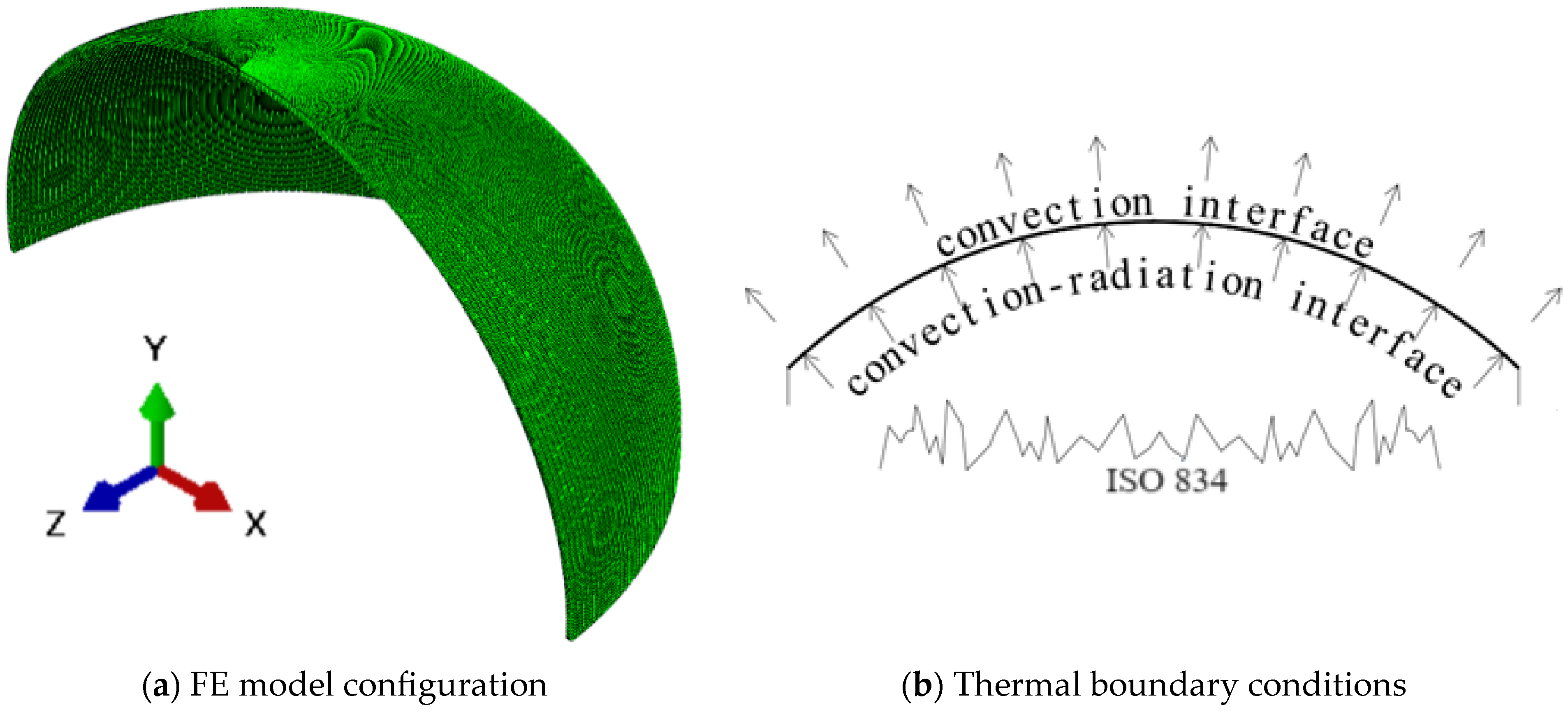
Figure 5 shows the FE model and thermal boundary conditions.
The number of elements through the dome thickness was determined based on sensitivity analysis. The number of elements through the thickness was varied from 2 to 8, and the temperature profile through the thickness and the apex’s vertical deflection were evaluated for each case. Thermal analysis was found to be invulnerable to the number of elements. This invulnerability could be attributed to the adequacy of the element’s quadratic shape function in predicting the temperature profile through the dome’s thickness. For structural analysis, the vertical deflection indicated that a mesh with four elements through the thickness is optimum. Consequently, the mesh size was varied from 12.5 mm to 50.0 mm.
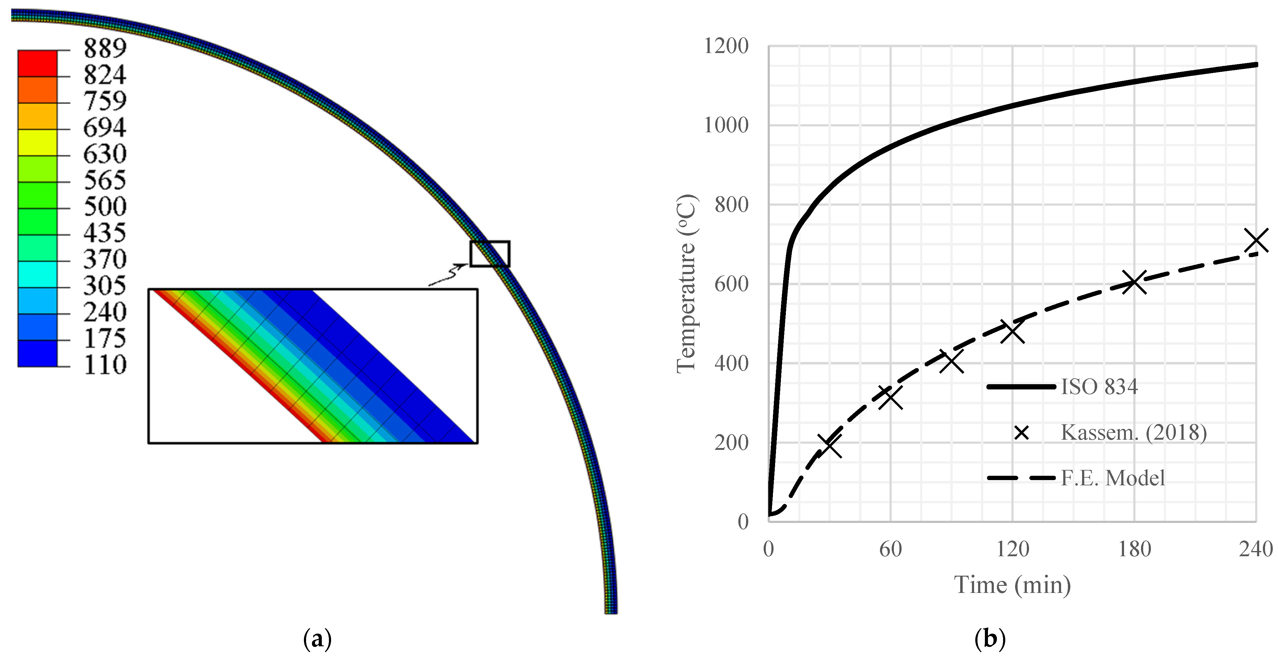
The thermal model was validated by comparing the average temperatures for a 100 mm thick dome with Kassem’s temperature profiles [
13].
Figure 6a shows the outputs of the validation model in the form of a temperature distribution through the dome’s thickness, while
Figure 6b shows the variation in the average dome temperature with time. The model was found to be in good agreement with reference data.
The structural model used the same nodes and elements as the thermal model, which allowed the transient temperatures resulting from thermal analysis to be applied to the structural model. The concrete damage plasticity (CDP) [
14] model was used to simulate concrete structural properties [
15]. Effects of elevated temperatures on the CDP model were accounted for following Bisby [
16], in conjunction with elevated temperature stress–strain parameters, as recommended by the Euro code [
10]. The parameters used were a dilation angle (
Ψ) of 35°, an eccentricity (
e) of 0.1, a ratio of the second stress invariant on the tension meridian to the second stress invariant on the compression meridian (
Kc) of 0.67, and a viscosity (
μ) of 0.001.
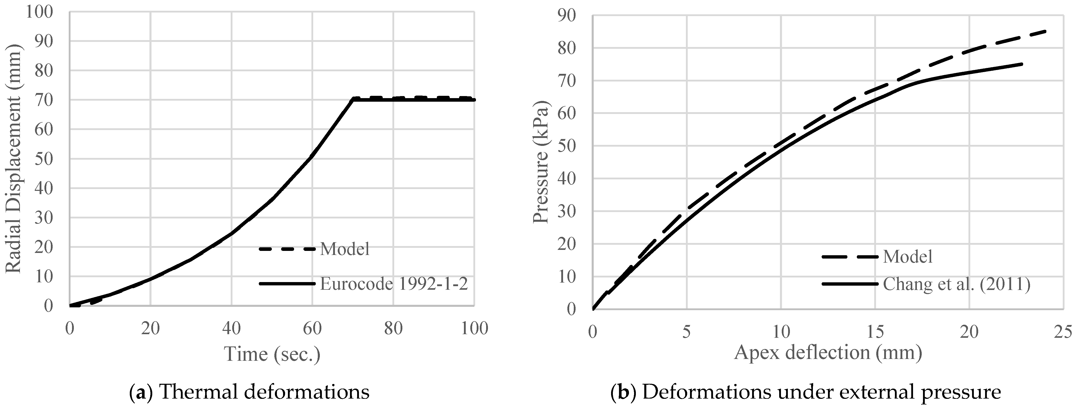
The structural model was validated by examining the thermal expansion and apex deflection under external pressure. The first structural validation model considered a laterally unrestrained 20 m diameter, 100 mm thick dome with all its nodes subjected to a temperature field linearly increasing from 20 °C to 1000 °C in 100 s.
Figure 7a shows radial displacements versus the fire duration. The numerically evaluated values matched the theoretical values calculated following the Euro code [
10].
The second validation used the experimental work by Chang [
17], where a partial concrete dome of diameter 22.63 m and thickness 30 mm was subjected to external pressure.
Figure 7b compares the dome’s apex vertical deflection predicted numerically to that obtained experimentally by Chang [
17]. The structural model slightly underestimated the apex deflection, which might be attributed to the steel ring beam used in the test to support the dome laterally, as it could not provide complete confinement.
3. Ring Reinforcement
Ring reinforcement was calculated to prevent ring failure before crushing in the meridian direction. This reinforcement is needed because of the developed ring tension for domes supporting gravitational loads. The maximum ring tension for a full dome is at its base (Φ = 90°), where
σmeridian = −
qa and
σhoop = qa. The CDP failure criterion is used to identify the needed ring reinforcement. The CDP failure envelope is defined by Equations (7) to (11) [
18], where
is the material uniaxial compressive strength (
f’c),
is the ratio between the initial biaxial and the uniaxial compressive strengths and
is the ratio between uniaxial compressive and tensile strengths. For the case of a spherical dome,
σ1 is the meridian stress, and
σ2 is the hoop stress. The meridional direction is considered unreinforced since it is compressed for both gravitational and external pressures. This assumption follows the common practice of using minimum reinforcement in domes to ensure the integrity of the concrete sections. In the case of gravitational loads and for Φ > 51.8°, the concrete tensile strength is ignored in the hoop direction since hoop stresses at failure are far beyond the concrete modulus of rupture. Consequently, the section is cracked, and only hoop reinforcement resists the tensile forces. Assuming failure in the hoop direction occurs when the steel yields, the behavior in the hoop direction becomes elastic [
19], which allows modeling the steel bars as equivalent concrete [
20] with a tensile strength of
, where
is the reinforcement ratio in the ring direction, and
fy is the steel yield stress.
To calculate the needed value of ring reinforcement, different values of
, which reflects the ring reinforcement ratio, were assumed. Assuming
= 1.16 [
21] and using Equations (7)–(11), the values of
can be determined. Applying the previous procedure for
f’c of 30 MPa and
fy of 400 MPa resulted in
Figure 8a, which shows the failure envelopes for different ring reinforcement ratios. The relationship between the meridian reinforcement ratio and hoop stress at failure, i.e., at
σmeridian = −
σhoop, is shown in
Figure 8b. The figure shows that the rate of increase in the meridian failure stress reduces above a ring reinforcement ratio of about 8%. Assuming this point corresponds to failure in the meridian direction, this ring reinforcement ratio was used in this research.
4. Parametric Study
The vulnerability of the dome’s fire endurance to thickness, slenderness, and central angle (partial dome) was examined through a parametric study.
Table 1 lists the considered configurations. The configuration name was M, followed by the thickness in centimeters and the diameter in meters. For example, M-10-20 refers to a 100 mm thick dome with a diameter of 20 m. All models had a ring reinforcement ratio of 8% placed in the middle of the thickness of the dome. The influence of the ring reinforcement ratio was assessed by creating two additional models with a ring reinforcement of 0% for high-slenderness-ratio configurations, M-5-20 and M-20-80. Eight models also examined the effects of base restraints and external pressure, considering M-10-5, M-10-10, M-10-20, and M-10-40. The load ratio varied from 30% to 90% of the ambient temperature failure load. The load was applied with standard fire exposure for up to 240 min. This range of the investigated load ratios covers the practical cases in the industry. It ensures that the compressive strain generated in the meridional direction exceeds the tensile strain generated from dome thermal expansion. A concrete characteristic strength of 30 MPa and a steel reinforcement yield strength of 400 MPa were considered for all cases.
The three considered thicknesses were within the practical range for concrete domes.
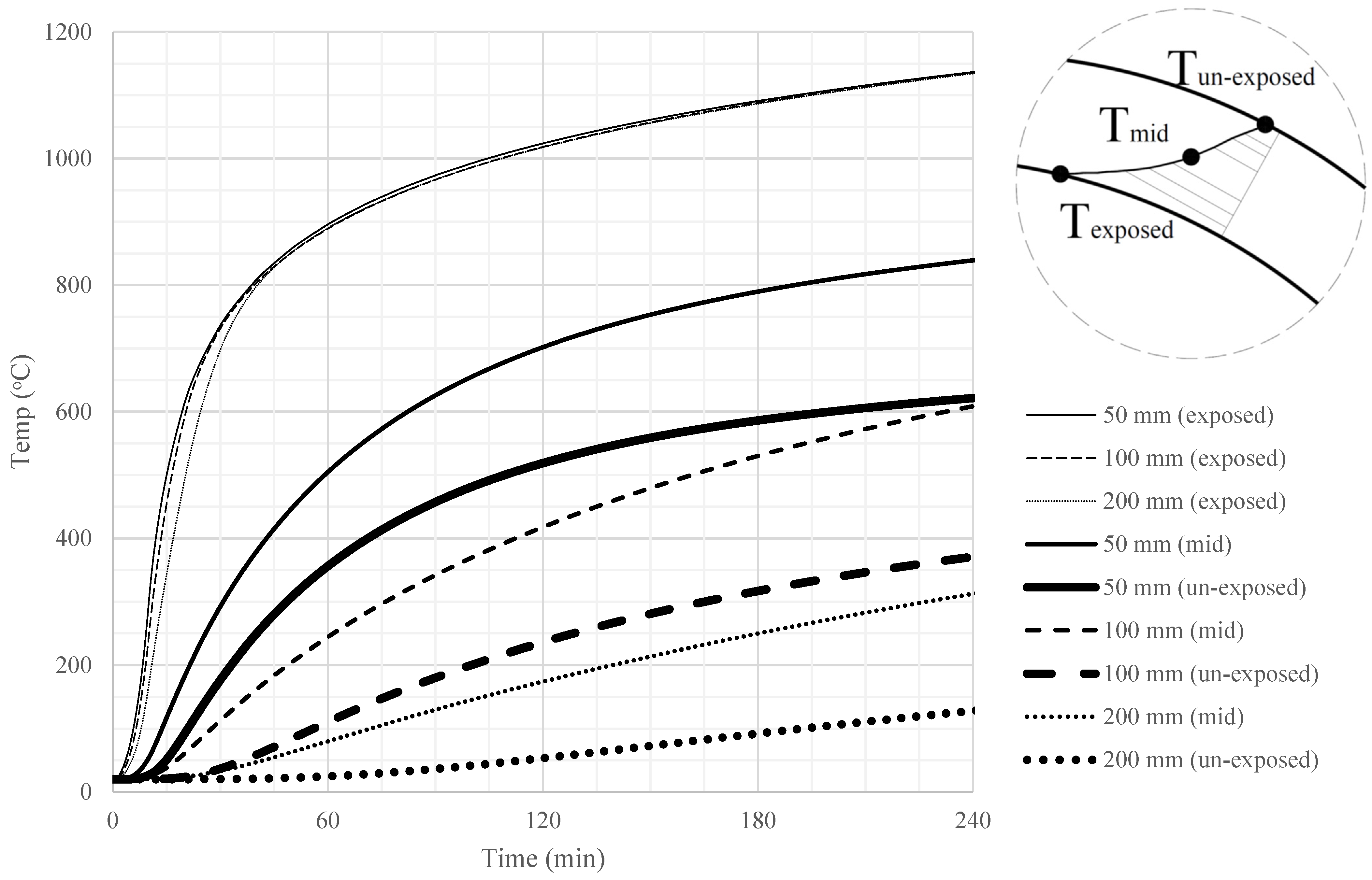
Figure 9 displays the transient temperatures of the inner (exposed), the mid-thickness, and the outer (unexposed) surfaces, considering exposure to ISO standard fire. The exposed surface temperature remained unchanged regardless of the dome thickness. However, the temperatures at the middle of the thickness and the outer surface were much higher for thinner domes.
The outcomes of the thermal analysis were extracted in the form of nodal temperatures and applied to the structural model.
Figure 10 shows the structural model configuration for the cases of full and partial domes, considering both gravitational and pressure loads and transient thermal temperature profiles. The lower boundary condition was set as either fixed to simulate a fully restrained dome or guided to simulate a laterally unrestrained case.
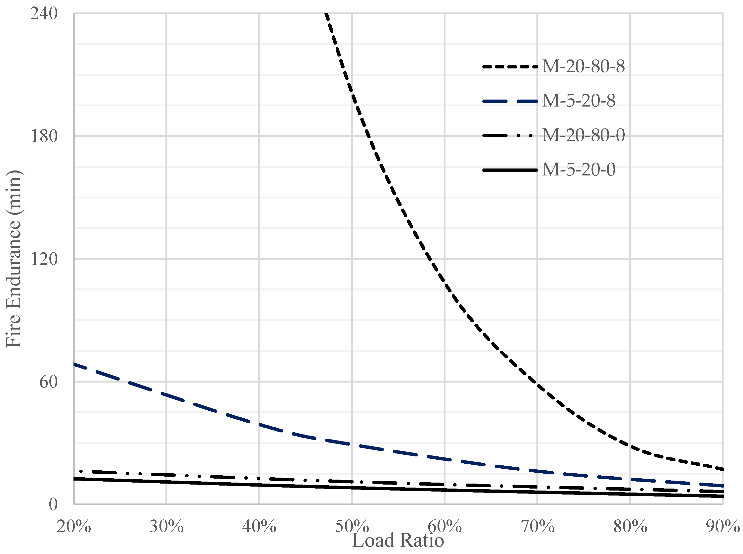
Figure 11 shows the effect of ring reinforcement on the fire endurance of concrete domes subjected to different gravitational load ratios. A 0 or 8 was added to the configuration name to identify the reinforcement ratio percentage. The 0% ring reinforcement ratio showed low fire endurance and invulnerability to the load ratio. The invulnerability could be attributed to a tensile failure in the ring direction shortly after fire exposure. For domes with ring reinforcement, failure in the ring direction was prevented. Thus, the dome fully used its concrete, and the behavior was controlled by the compression happening in the meridian direction.
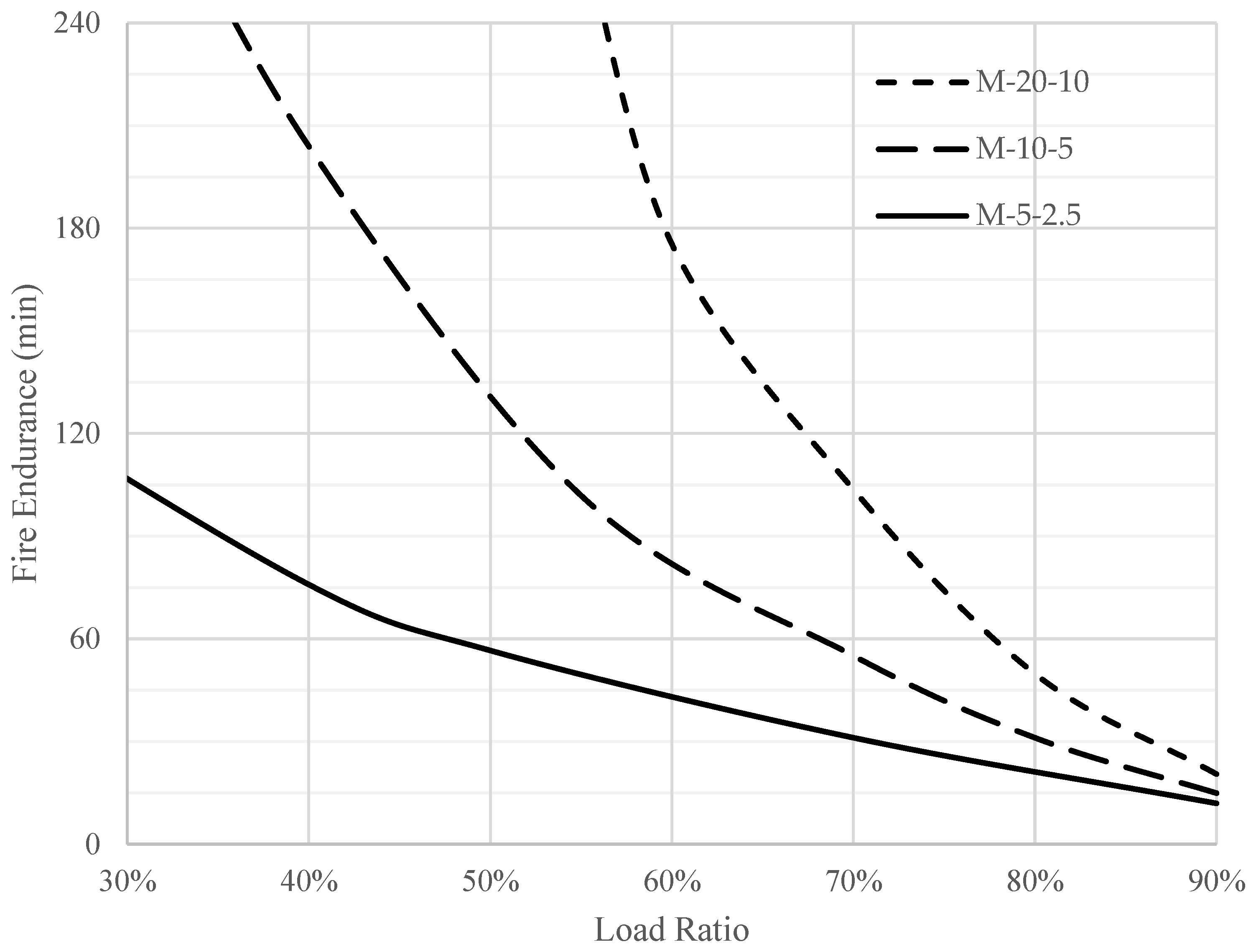
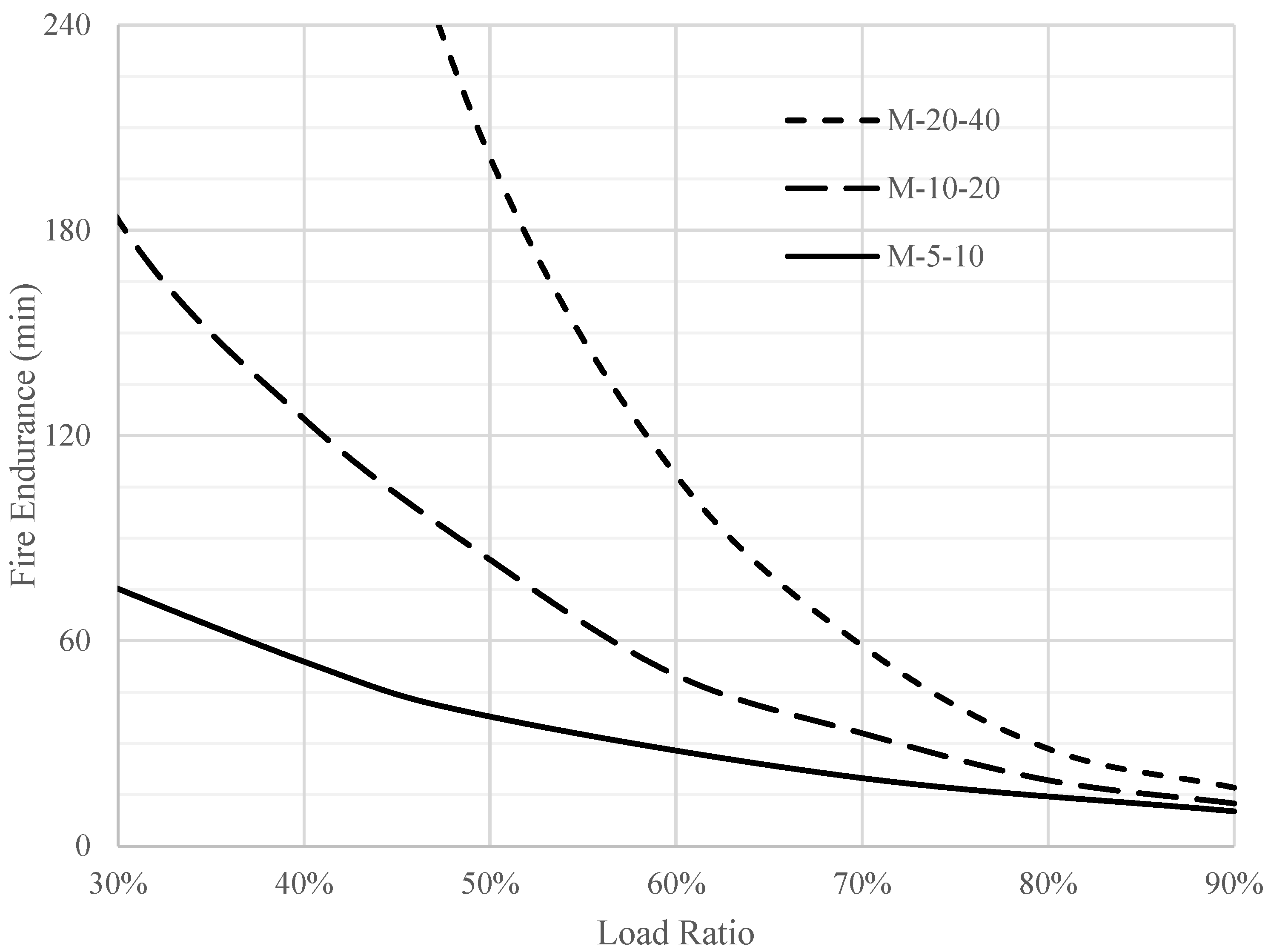
Figure 12 and
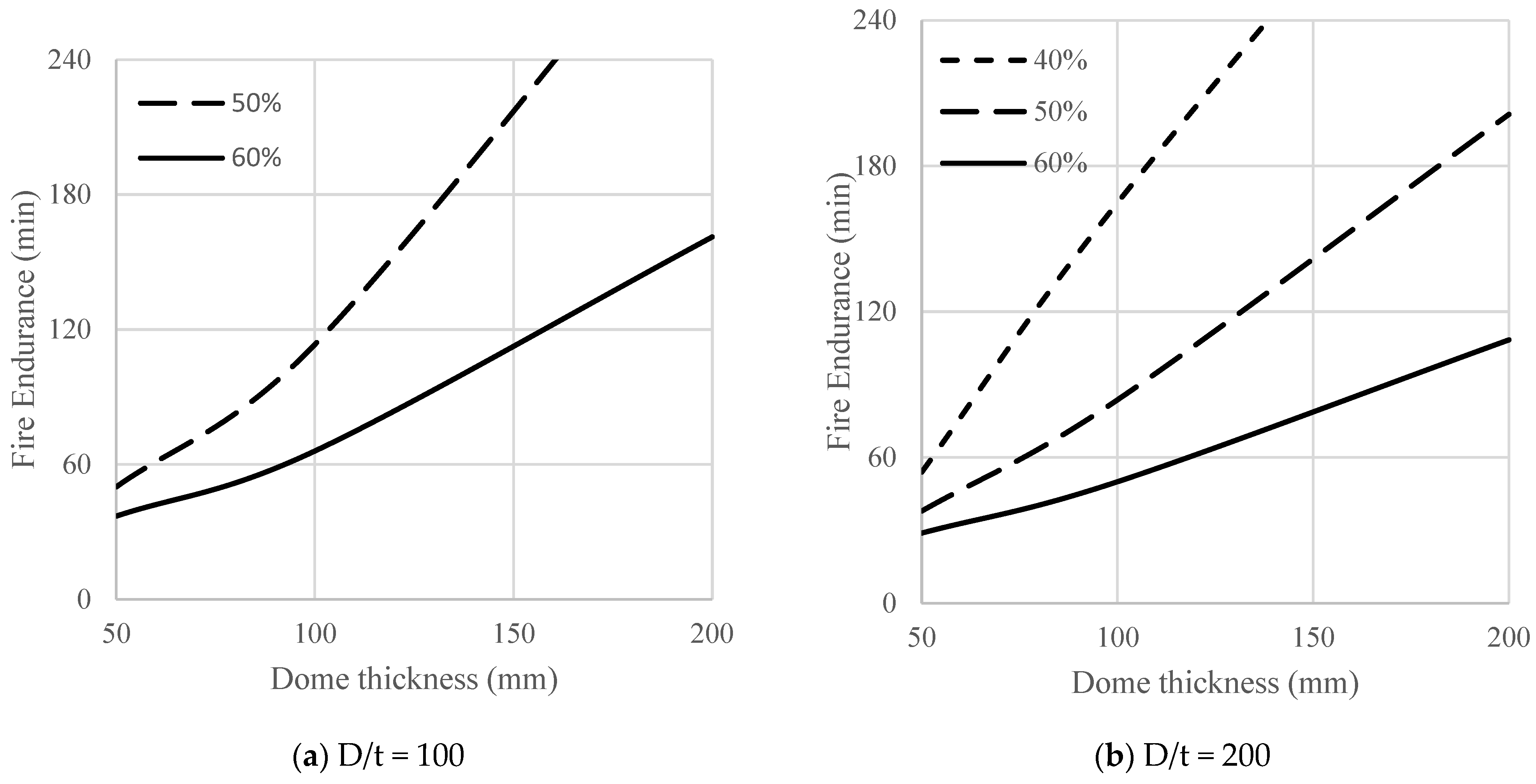
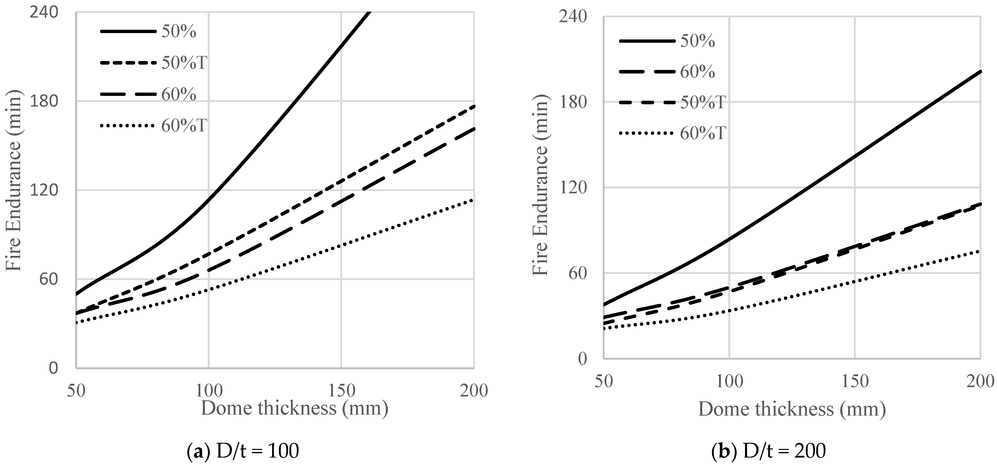
Figure 13 represent the effects of dome thickness on fire endurance for slenderness ratios (D/t) of 50 and 200. The figures show that the thicker the dome, the greater the fire endurance. This increase in fire endurance is related to the reduced concrete mean temperature for thicker domes. Consequently, there is less concrete degradation.
Figure 14 represents the direct effect of dome thickness on fire endurance for typical design load ratios (40% to 60%). For a load ratio of 40% and D/t of 100, failure did not happen within the assumed 240 min of fire exposure. The figure shows that fire endurance significantly increases as the thickness increases. It also indicates that domes with a thickness of 50 mm have a fire endurance of less than 60 min.
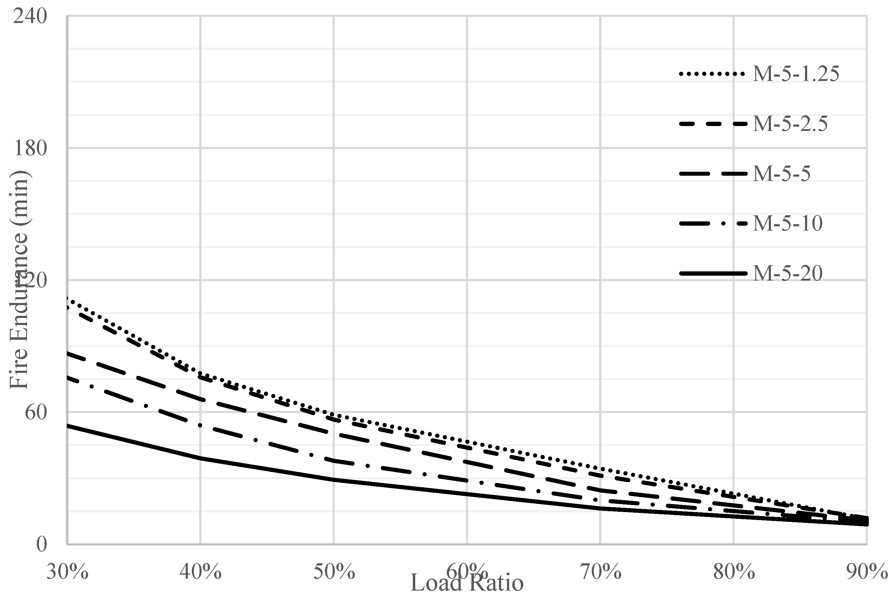
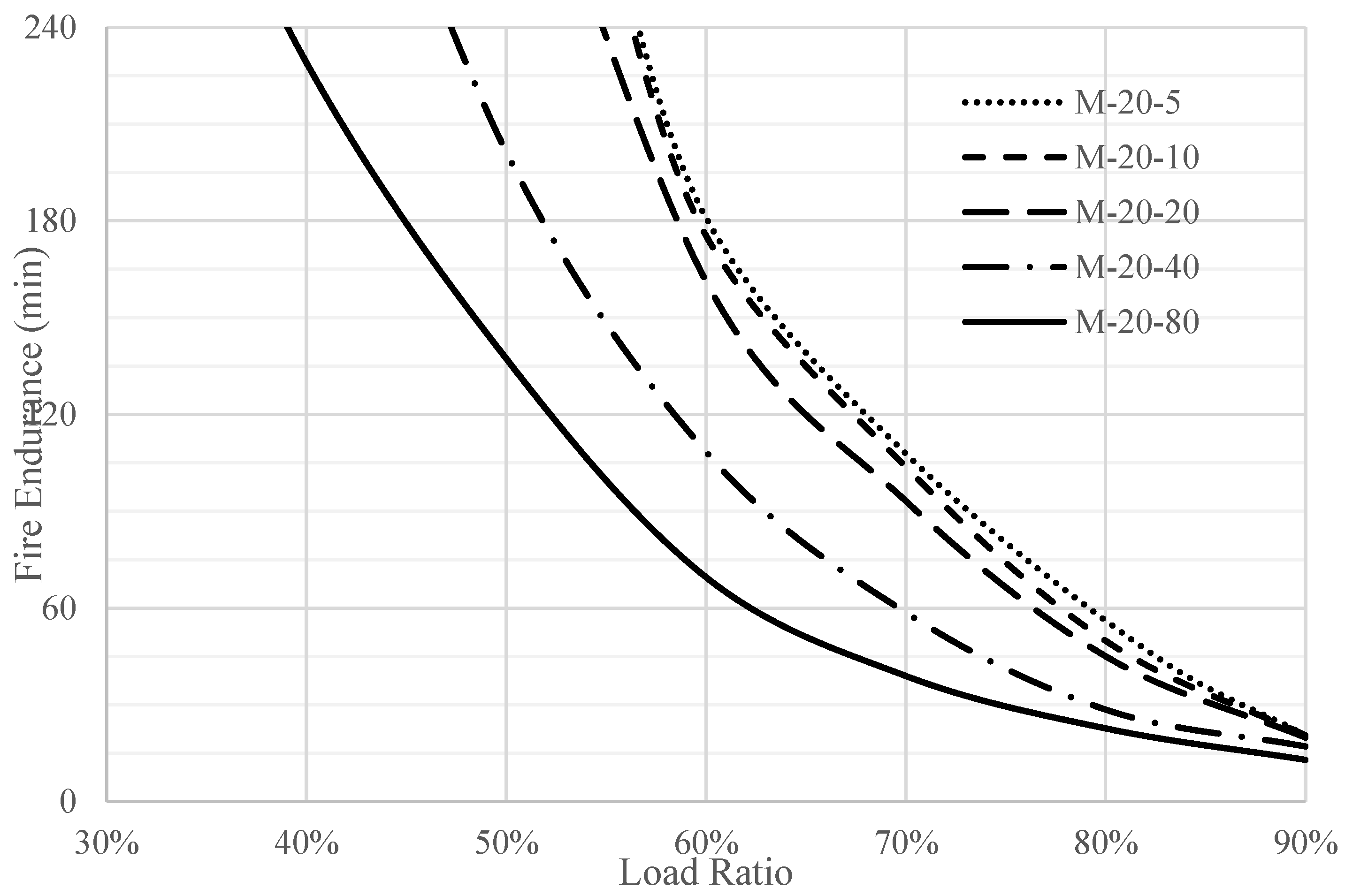
The effect of the slenderness ratio on the fire endurance of full domes was investigated, as shown in
Figure 15 and
Figure 16. The figures clearly show that more slenderness leads to less fire endurance. This observation can be explained by the excessive rotations resulting from the steep temperature gradient in thin domes. However, the fire endurance of domes with low slenderness ratios is approximately the same.
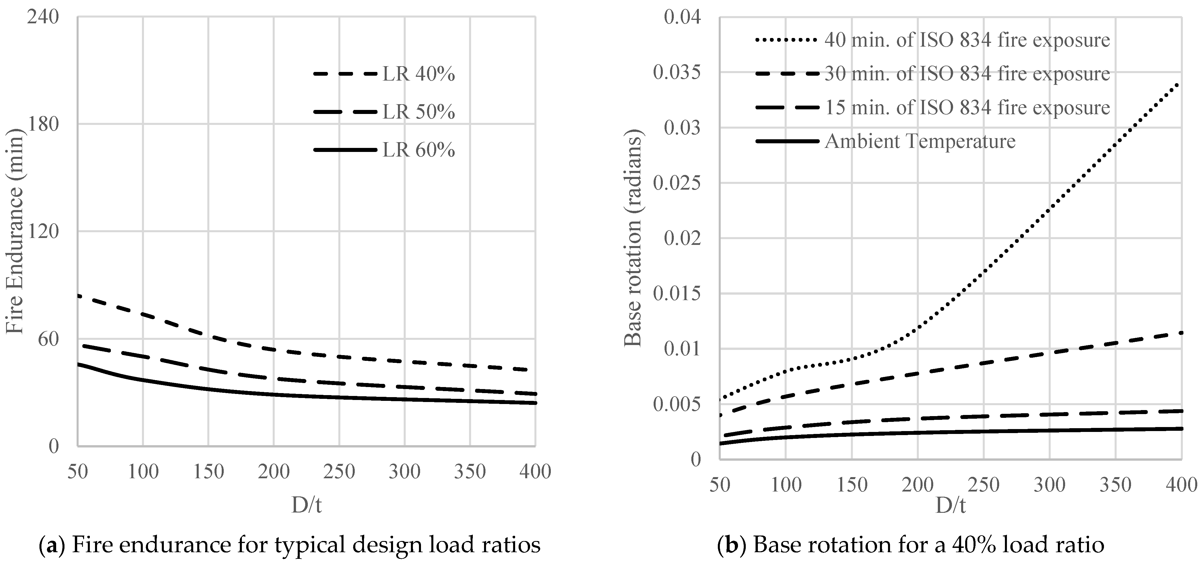
Figure 17a represents the effect of dome stiffness on fire endurance within typical design load ratios (40% to 60%) for a 50 mm thick dome. It shows a reduction in the effect of the load ratio as the slenderness ratio increases, reflecting the role of stiffness in maintaining membrane action, where domes of high slenderness suffer rotational instabilities and consequently fail at a low fire endurance, as presented in
Figure 17b.
The behavior of partial domes was considered by modeling a partial dome with a central angle
Φ of 40°. This angle is less than 51.8°, ensuring compressive hoop stress.
Figure 18 shows that the fire endurance of partial domes (labeled T in the figure caption) is significantly less than that of full domes of the same curvature, which can be attributed to the development of flexure stresses resulting from the base reaction.
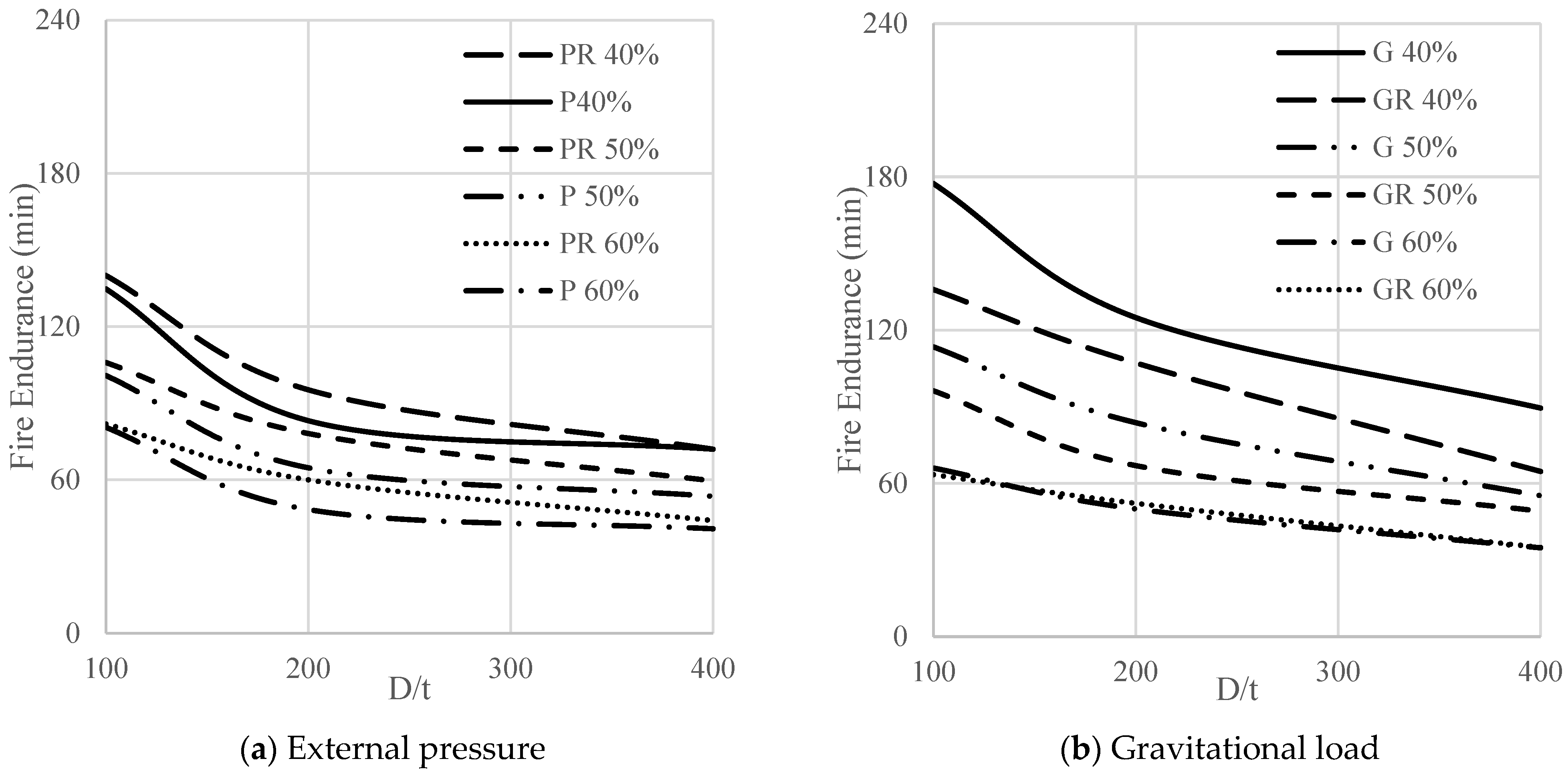
Figure 19a shows that laterally unrestrained domes subjected to pressure (P) show no significant decrease in fire endurance for a slenderness ratio exceeding (D/t) = 200. The pressure led to uniform ring compression, stabilizing the slender dome and increasing fire endurance. Laterally restrained full domes (PR) had higher fire endurance than laterally unrestrained full domes (P), as the lateral restraint reaction resulting from thermal expansion provided additional confinement for the dome.
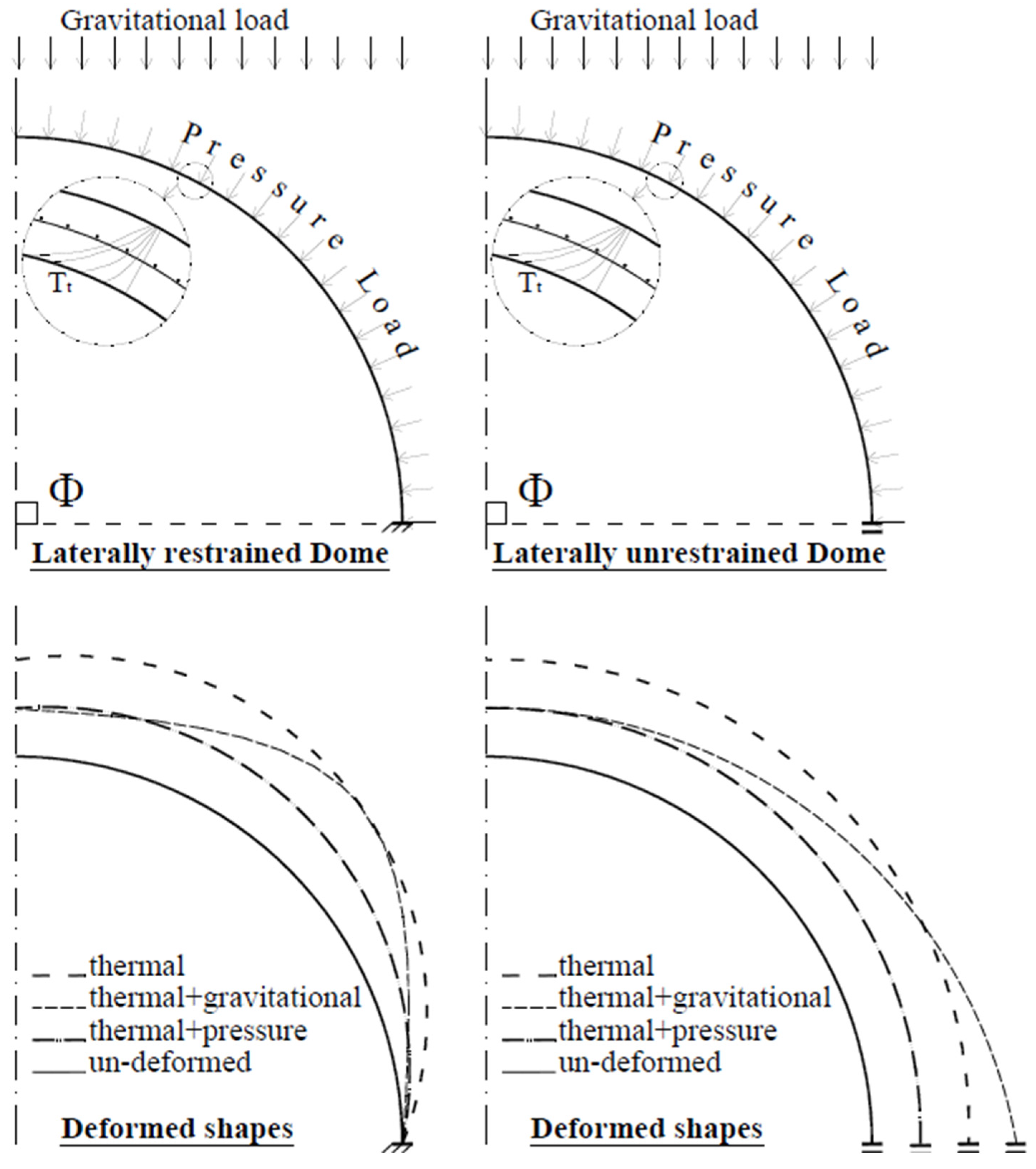
Figure 19b shows that laterally restrained full domes subjected to gravitational loads (GR) showed less fire endurance than laterally unrestrained (G) ones, mainly due to the orthogonality of gravitational loads and the lateral restraint reaction. This orthogonality led to flexural deformations, decreasing fire endurance.
Figure 20 compares the lateral restraint effects on domes subjected to a fire incident associated with gravitational or external pressure loads. The figure presents a simple illustration of the experienced thermal-structural deformations, considering fixed and guided boundary conditions.


