1. Introduction
To transport atoms to be deposited and accelerate particles from their sources to a workpiece surface in a vacuum chamber, their mean free path must exceed ~10 cm. For this reason, these particles are most often produced using high-frequency [
1], vacuum-arc [
2,
3], and magnetron [
4] discharges at gas pressures below ~0.1 Pa. To fill a large working volume with uniform plasma, a discharge with thermionic cathodes and a peripheral magnetic field on the chamber walls, which limits electron escape to the walls, is also used. In this case, a cylindrical hollow cathode with an internal diameter of several millimeters made of refractory metal is often used as a thermionic cathode [
5]. Gas is fed into the chamber through the cathode orifice; a discharge with a current of up to hundreds of amperes at a pressure of hundreds of pascals and a voltage of tens of volts maintains a dense plasma within the cathode. This plasma emits ions onto its surface, and their current of up to 100 A maintains the high cathode temperature necessary for thermionic emission of electrons.
As for the cold hollow cathode discharge [
6], the range of its applications for surface treatment was limited by a relatively high operating gas pressure. Several decades ago, there was a complete lack of data in the literature on cold cathode glow discharge without magnetic field at a gas pressure below 1 Pa. At the same time, research and practical application results indicated that hollow cathode glow discharge was capable of generating ion and electron beams, as well as a dense plasma uniform throughout the cathode cavity. As the current increased, the concentration of metal atoms and ions in the plasma reached a level sufficient, for example, for high-speed coating deposition.
There were no established concepts regarding the discharge mechanism and the factors, which determine the value of its lower operating pressure. It was universally recognized that the gas inside the hollow cathode is ionized by fast electrons emitted from the cathode surface and accelerated in the sheath between the cathode and plasma. After flying through the plasma, they are reflected back to the plasma in the opposite cathode sheath and then reciprocate in the hollow cathode.
When, with decreasing pressure, the average length of the electrons’ path Λ, along which they spend all the initial energy on ionizing the gas, becomes greater than their average path L inside the cathode hollow before leaving it, for example, through the ends of a cylindrical hollow cathode, current of the discharge decreases and it expires.
Another explanation for the discharge decay is based on a comparison of the cathode cavity width and the mean free path of electrons emitted by the cathode. After ionizing collisions, electron energy becomes less than the value required to return to the cathode surface. When, with decreasing pressure, the mean free path of electrons emitted by the cathode becomes greater than the cathode width, for example, the diameter of a cylindrical hollow cathode, then the electrons can reach the cathode and be absorbed by its surface.
The ionization cross-section of argon by electron impact amounts to σ = 1.5 × 10
−20 m
2 at an electron energy of 400 eV [
7] corresponding to the hollow cathode glow discharge typical fall of potential of ~400 V. At a gas pressure of
p = 10 Pa and room temperature, the density of molecules
no = 2.5 × 10
21 m
–3 [
8] and the mean path of those electrons in argon between ionizing collisions amounts to λ = 1/
noσ = (2.5 × 1.5 × 10
21−20)
−1 = 0.026 m = 2.6 cm. With a hollow cathode diameter of 2.6 cm, electrons emitted by the cathode at an argon pressure of less than 10 Pa can reach the opposite cathode fall region without energy loss and be absorbed by the cathode surface. In this case,
po = 10 Pa is the lower limit of the discharge operating pressure.
A number of scientific studies have experimentally confirmed that, at the lower operating pressure of discharges with 1–3 cm diameter hollow cathodes, the electron mean free path is approximately equal to the cathode diameter. Therefore, discharge extinction may be actually due to the absorption of emitted by the cathode electrons by its surface.
To fully verify this, a study was conducted in [
9] of a discharge with a 90 cm long and 20 cm diameter hollow cathode. As the cathode diameter increased by 20/2.6 = 7.7 times compared to the above case of 2.6 cm, we could hope that the lower limit of operating pressure should decrease by 7.7 times from
po = 10 Pa to
po = 1.3 Pa. However, when one end of the cathode was closed with a disk and the other was covered with a diaphragm having a 5 cm diameter hole in the center, the discharge stopped when the argon pressure decreased to
po~0.02 Pa, which is two orders of magnitude less than the expected value of
po = 1.3 Pa.
The obtained result shows that absorption of emitted by the cathode electrons with its own surface can hardly be the reason for the discharge decay with decreasing pressure. Changing the diameter of the diaphragm hole and the cathode length, it was found in [
9] that the lower limit of operating pressure
po is proportional to the area
So of the diaphragm hole, which is the aperture of the electron loss from the cathode. This indicates that
po is determined with the escape of fast electrons from the cathode.
When the ratio of So to the area S of the hollow cathode inner surface is decreasing to So/S = (2m/M)1/2, where m is electron mass and M is the mass of the ion, with the plasma passing through the diaphragm hole a bright double layer is observed. With decreasing pressure, the double layer decays and the discharge expires. For this reason, to keep the discharge the area So of the diaphragm hole should exceed S* = (2m/M)1/2S.
When the anode is placed inside a large closed hollow cathode, fast electrons oscillating inside the cathode can be absorbed only by the anode surface. When, with decreasing pressure, the average length of the electrons path Λ, along which they spend all the initial energy on ionizing the gas, exceeds their pass to the anode L = 4V/Sa, where V is the cathode volume and Sa is the anode surface area, the discharge ceases. For this reason, the lower limit of operating pressure is proportional to the anode surface area Sa.
When the anode surface area Sa decreases, its potential remains negative to the plasma until Sa reaches the value Sa = S* = (2m/M)1/2S. At Sa ˂ S* a positive anode potential appears, and its value amounts to ~10 V at the gas pressure p~0.1–1 Pa and grows to ~500 V with the pressure decreasing to p~0.02 Pa. At a discharge current of 4 A, the power of accelerated electrons heating the titanium rod anode is 2 kW, and the tip of the anode melts.
Any vacuum chamber made of conductive material can be used as a large closed hollow cathode after an anode is placed inside it. A glow discharge can fill the chamber with a homogeneous and dense plasma suitable for various technological applications. To feed the glow discharge, which is prone to transition to arc mode, a power supply with arc protection should be used.
The aim of this work is to demonstrate some technological capabilities of hollow cathode glow discharge plasma, which became available after the lower limit of the discharge pressure was reduced by two orders of magnitude in [
9].
2. Materials and Methods
2.1. Filling a Chamber with Homogeneous Plasma
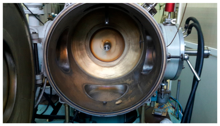
The vacuum chamber of the experimental system (
Figure 1) is 50 cm in diameter and 60 cm long. At opposite ends of the chamber are two doors.
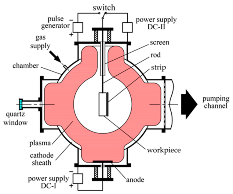
The general scheme of the experimental system is presented in
Figure 2. A disk anode is installed at the bottom of the chamber, and a high-voltage feedthrough insulator is located at the top. Between the anode and the chamber is connected an arc protected DC-I power supply with a current up to 10 A at a voltage up to 700 V. The working gas enters the chamber through a connecting pipe and is evacuated through a broad grounded grid by a pumping system. The inner volume of the chamber is
V = 0.12 m
3 and the area of its walls cooled with water amounts to
S = 1.5 m
2. A 5 mm diameter molybdenum rod is fastened to the upper flange of the high-voltage feedthrough and is used as a holder for a workpiece suspended in the center of the chamber. The rod is protected from the plasma with a screen made of a stainless-steel tube with an inner diameter of 10 mm, which is fastened to the upper flange of the chamber.
Another power supply, DC-II, with a current up to 2 A and a voltage up to 5 kV can be connected between the chamber and molybdenum rod of the high-voltage feedthrough using a switch. The rod can be connected to either the negative or positive pole of this power supply. In the first case, it allows negative biasing of a workpiece for etching and heating it with accelerated ions. In the second case, power supply DC-II replaces DC-I after the latter is turned off, the disk anode is electrically connected to the chamber, and a conductive workpiece in the chamber connected to the molybdenum rod is used as the anode.
A pulse generator can be connected between the molybdenum rod of high-voltage feedthrough and the chamber. It can apply to the workpiece 50 µs wide negative pulses with amplitude up to 40 kV and a repetition frequency up to 50 Hz. The voltage pulses are registered with a GDS–72104 oscilloscope produced by GW Instek company (New Taipei City, Taiwan) using a voltage divider, and the pulses of current in the workpiece circuit are simultaneously registered with the same oscilloscope using a Rogowski coil. To measure the temperature of the workpiece using a pyrometer, a quartz window is installed on the side flange.
After the gas discharge is ignited, the chamber is filled with a homogeneous plasma separated with sheaths from the chamber and the workpiece inside it. At an argon pressure of ~0.1 Pa and discharge current of I = 4 A, voltage Uc between plasma and the chamber amounts to Uc ≈ 420 V. When current decreases to I = 1 A, the value of Uc decreases to 400 V, and when the current increases to I = 10 A, the value of Uc increases to 460 V.
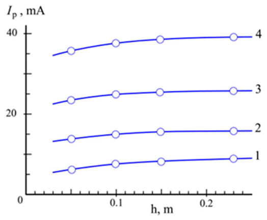
A movable disk probe with a diameter of 40 mm is used to measure the plasma density distribution in the chamber. It is attached to the end of a 6 mm diameter ceramic tube and through a conductor inside the tube and an ammeter is electrically connected to the chamber. A seal of the tube, located in place of the quartz window, ensures the disk movement between the flange of the chamber and its axis.
Figure 3 presents the results of probe current measuring at various distances
h from the chamber flange and discharge currents.
They indicate a fairly high plasma homogeneity within the chamber. Thus, at a current of I = 2 A in the central zone of the chamber from h = 5 cm to h = 30 cm, the current Ip varies from 35 mA to 39 mA, and nonuniformity of plasma density does not exceed ±5%.
The plasma’s high homogeneity is due to the multiple oscillations of fast electrons within the chamber. During hundreds of reflections in the cathode sheath, electrons always change direction and can visit any part of the chamber. For this reason, the probability of gas ionization is distributed over chamber volume fairly evenly.
2.2. Heating and Melting Metals in Vacuum
Once the disk anode (see
Figure 2) was connected to the chamber, another anode in the shape of a 7 × 7 cm
2 square made of 2 mm thick titanium sheet was suspended in the center of the chamber under the rod of the high-voltage feedthrough. The rod was connected to the positive pole of power supply DC-II and at the discharge current of 0.5 A in the anode circuit a decrease in argon pressure to
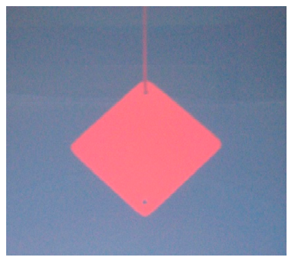
p ˂ 0.02 Pa resulted in an increase in the discharge voltage to 1–3 kV. Accelerated in the cathode sheath, electrons heat the anode quite homogeneously. This is evidenced by the even red color of its surface (
Figure 4).
When another electrode in the shape of a 3 × 3 cm2 square made of 2 mm thick titanium sheet is placed at any other point inside the chamber, it continues to glow equally regardless of its location and orientation. This indicates that distribution of fast electrons oscillating in the chamber can be considered uniform and isotropic.
After the 7 × 7 cm
2 anode of the discharge in argon was replaced with a 3 × 3 cm
2 anode, its surface area reduced to the value
Sa ˂
S* = (2
m/
M)
1/2S = 82 cm
2 and a positive potential of the anode appeared. At the gas pressure
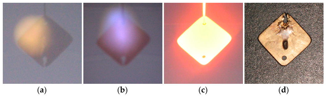
p~0.1 Pa its value amounts to ~10 V and a bright yellow glow is seen on the anode (
Figure 5a). As the pressure decreases, the glow changes its color to violet, increases in size and envelops the whole anode (
Figure 5b). After that it disappears, the positive potential fall of the anode increases to ~500 V at a pressure of
p~0.02 Pa, and the anode heats up and melts (
Figure 5c). The heated anode is yellow in color, except for the sharp corners and the molybdenum wire supporting it, which are heated to white by electrons extracted from the plasma in a strong electric field. As soon as the anode began to melt, it fell to the bottom of the chamber (
Figure 5d).
When a 6 mm diameter and 100 mm long rod anode was suspended in the chamber, at argon pressure p~0.1 Pa, a bright glowing ball of anode plasma was observed on the tip of the titanium rod. With pressure decreasing, the ball diameter increased from 1 to 4 cm at the pressure p~0.03 Pa and intensity of the anode plasma glow appreciably diminished. Finally, glowing of anode plasma disappeared and at a constant discharge current of I = 4 A the discharge voltage started a rapid increase to U~1 kV at p~0.01 Pa.
Measuring floating potential of a probe immersed in the discharge plasma showed that the discharge voltage U is the sum of anode fall of potential Ua and cathode fall of potential Uc. At a rapid increase of U = Uc + Ua the cathode fall keeps a constant value of Uc~500 V and the anode fall Ua rises to 500 V and even higher. Therefore, the power of electrons heating the anode can account for the majority of the total discharge power.
In the case of the 6 mm diameter rod the heating power was 4 A × 0.5 kV = 2 kW. It was quite enough for melting titanium, with melting point of 1670 °C. Melting of the rod begins from its lower tip, and the liquid metal drips into a ceramic crucible located under the anode.
2.3. Thermochemical Treatment of Metal Parts
Among thermochemical treatments for titanium alloys, nitriding is the most widely used. It is carried out in nitrogen or a nitrogen–argon mixture at temperatures of 850–950 °C for 10–50 h. The microstructure of the nitrided layer consists of a brittle 5–20 µm thick surface nitride layer and a 0.1–0.15 mm thick layer of nitrogen solid solution in α-titanium with a hardness of 8–10 GPa. The brittle layer is removed from the surface by grinding. Nitriding time appreciably decreases at lower gas pressure [
10,
11,
12,
13]. After nitriding, titanium alloy parts exhibit good antifriction properties, increased fatigue strength, corrosion resistance, and high wear resistance.
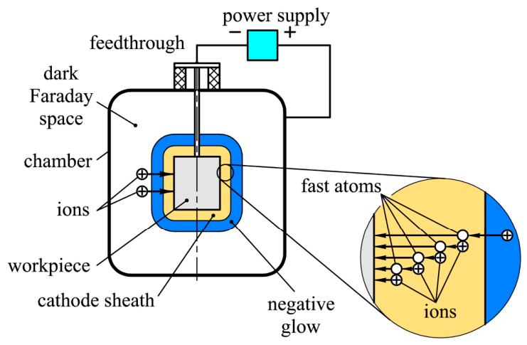
Nitriding is also used for hardening steel parts. A standard ion nitriding system includes a vacuum chamber with a steel workpiece suspended under a high-voltage feedthrough (
Figure 6). When at nitrogen pressure
p a negative voltage of
U = 700 V is applied to the workpiece, glow discharge is established with ion current density
j on the cathode surface.
Applied to the workpiece negative voltage, for example, 700 V initiates an abnormal glow discharge between the chamber (anode) and the workpiece (cathode). In this discharge the value of
j/
p2, where
j is current density on the cathode and
p is the gas pressure, depends only on the discharge voltage
U. At nitrogen pressure
p~50 Pa and
U = 700 V, the workpiece is covered with blue negative glow of the discharge plasma, and width of the sheath between plasma and workpiece is
d = 4 mm [
14]. As at
p~50 Pa the charge exchange length is 0.2 mm, and the charge of one ion is transported through a 4 mm thick sheath by about 20 particles. Their mean energy 700/20 = 35 eV is not enough for defects of the structure, which could substantially increase the nitriding rate. For this reason, it takes more than 10 h to obtain a nitrided layer with a thickness of 100 µm, the same as with titanium nitriding.
It was shown in [
1] that nitriding time reduces by an order of magnitude at the gas pressure
p~0.1 Pa. This is because at low pressure the charge exchange length becomes greater than the width of the cathode sheath, and accelerated ions pass from the plasma to the surface of the workpiece without collisions and energy loss.
A 4 cm broad, 4 cm wide and 11 cm long workpiece made of AISI 5135 steel was suspended in the center of the chamber under the rod of high-voltage feedthrough (see
Figure 2). A 10 mm wide, 2 mm thick and 110 mm long strip made of the same steel was attached to the workpiece using screws.
After turning on the power supply DC-I at nitrogen pressure p = 0.1 Pa, a glow discharge is established with current of I = 4 A at cathode fall of Uc ≈ 400 V. The widths d of positive space charge sheaths on the cathode and on the workpiece are both equal to d = 6.6 mm. An increase in the workpiece bias voltage from 400 to 1000 V results in an increase in the width d of the sheath between the workpiece and plasma from 6.6 to 8.5 mm.
Nevertheless, at nitrogen pressure p = 0.1 Pa the charge exchange lengths of ions λ = 1/noσ = 0.17 m, where no = 2.5 × 10¹⁹ m–3 is density of gas molecules and σ = 23 × 10−20 m2 is charge exchange cross-section of nitrogen ions, are 17/0.85 = 20 times larger than the sheath width d. It means that accelerated ions pass from the plasma to the surface of the workpiece without collisions and energy loss.
When an accelerated ion collides with an atom of the workpiece substance, the latter is displaced from its equilibrium position due to recoil. As a result of a large number of such collisions, the order of the atoms in the crystal lattice is disrupted, and the crystalline substance transitions to an amorphous state. Each displaced atom collides with other atoms and dislodges them from the crystal lattice sites. These, in turn, dislodge other atoms, and so on. Thus, a cascade of collisions develops, ceasing only when the energy of each displaced atom becomes less than the threshold energy of atomic displacement εd. The number of substance atoms displaced by one ion with initial energy εo in the elastic sphere model is equal to Nd = εo/2εd. For a steel workpiece εd = 20 eV and εo = 1000 eV, hence in our case each accelerated ion produces Nd = 25 displaced atoms. The defects produced substantially facilitate penetration of nitrogen into the workpiece surface.
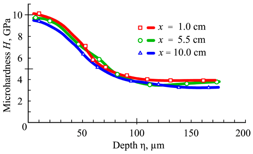
The workpiece made of AISI 5135 steel with an attached strip made of the same steel was nitrided for two hours at the temperature ~580 °C. After processing, the strip was disconnected from the workpiece, cut into pieces and ground cross-sections were produced to measure the microhardness
H of its material at different depths
η from the strip surface.
Figure 7 presents dependencies of
H on the depth
η at different distances from the end of the strip
x = 1, 5.5, and 10 cm. They allowed estimation of the thickness of the hardened surface layer ~ 100 µm, the maximum hardness on the surface ~10 GPa and hardness of the bulk ~3.5 GPa. The obtained results demonstrate quite good homogeneity of the surface nitriding.
2.4. Plasma Immersion Ion Implantation
To implant any necessary chemical elements into the surface layer of any workpiece, an ion source or a source of fast neutral atoms [
15,
16] with an energy of 50–100 eV can be used. However, plasma immersion implantation differs in that it allows for the simultaneous processing of the entire surface of the workpiece, which simplifies the processing and makes it more convenient. The only problem is generation of a dense plasma at low gas pressure.
To find out how the implantation of nitrogen influences the workpiece, a 4 cm thick, 4 cm wide and 11 cm long workpiece made of AISI 321 steel was suspended in the center of the chamber under the rod of high-voltage feedthrough (see
Figure 2). A 10 mm wide, 2 mm thick and 110 mm long strip made of the same steel was attached to the workpiece using screws.
At argon pressure
p = 0.05 Pa,
I = 4 A and
Uc ≈ 420 V, the density of ion current from plasma to the hollow cathode surface with area of
S = 1.5 cm
2 amounts to
j =
I/
S = 4/1.5 = 2.67 A/m
2. The width
d of the positive space charge sheath between the cathode and plasma and between the workpiece and plasma was calculated according to Child–Langmuir’ law [
17]:
where ε
o = 8.85 × 10
−4 F/m is the electrical constant,
e is electron charge and
M is the ion mass, amounting to
d = 5.3 mm. The width of the sheath between the argon plasma and the workpiece amounts to
d~17 cm when exposed to a 40 kV voltage pulse (see
Figure 2).
At nitrogen pressure p = 0.05 Pa, I = 4 A, Uc ≈ 400 V the widths d of positive space charge sheaths between the cathode and plasma and between the workpiece and plasma are both equal to d = 6.6 mm. The width of the sheath between the nitrogen plasma and the workpiece amounts to d~20 cm when exposed to a 40 kV voltage pulse.
The ions extracted from the plasma and accelerated in the high-voltage sheath can lose their energy as a result of charge exchange collisions.
At a pressure of
p = 0.05 Pa, the density of gas atoms can be considered equal to
no = 1.25 × 10
19 m
–3 [
8]. The charge exchange cross-sections of argon and nitrogen ions with an energy of 6 keV are equal, correspondingly, to σ = 17 × 10
–20 m
2 and 23 × 10
−20 m
2 [
18,
19], and the charge exchange lengths of ions λ = 1/
noσ are equal to 0.48 m for argon and 0.34 m for nitrogen.
In both cases, the charge exchange length exceeds the width of the space charge sheath between the plasma and the workpiece, and increasing the pulse amplitude from 6 to 40 kV makes it even larger. Hence, all ions pass through the sheath without collisions and strike the workpiece surface with an energy of 40 keV. They penetrate into the surface layer of the workpiece and substantially change its properties.
At nitrogen pressure
p = 0.05 Pa and discharge current of
I = 4 A, the workpiece was first processed for 15 min with ions accelerated by a negative bias voltage of 800 V applied from the DC-II power supply. Then, using the switch (see
Figure 2), the workpiece was disconnected from the DC-II power supply and connected to the pulse generator. High-voltage pulses with an amplitude of 40 kV, width of 50 μs, and repetition rate of 50 Hz were applied to the workpiece for one hour. Measuring with an IMPAC IP 140 infrared pyrometer manufactured by LumaSense Technologies GmbH (Raunheim, Germany) showed that the workpiece temperature of 480 °C, reached after 15 min of pretreatment, increased to 650 °C after one hour of treatment by high-voltage pulses.
After the treatment, the workpiece was taken from the chamber and the 110 mm long strip (see
Figure 2) was removed from the workpiece surface. The strip was then cut and ground cross-sections were produced to measure the microhardness
H of its material at different depths
η from the strip surface.
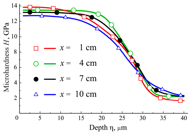
Figure 8 presents dependencies of
H on the depth
η at different distances from the end of the strip
x = 1, 4, 7 and 10 cm.
They are similar to each other and allow estimations of the maximum hardness in the modified surface layer H~13 GPa and the hardened layer thickness of δ~40 µm. The similarity of obtained distributions indicates the homogeneity of the effect of fast ions on the surface of the workpiece when its dimensions are smaller than the width of the high-voltage sheath. It allows a simultaneous hardening of the whole workpiece surface without scanning it, which makes the process simpler and more convenient. In addition to the sixfold increase in surface microhardness, implantation can affect its roughness.
Another 110 mm long, 20 mm wide and 2 mm thick strip was produced from AISI 321 steel and mechanically polished. Using a high-precision Dektak XT profilometer manufactured by Bruker Nano Inc. (Billerica, MA, USA) its initial roughness was Ra~0.02 µm. The strip was ultrasonically cleaned and screwed to the same workpiece (
Figure 2). It was then etched along with the workpiece for 15 min with 800 eV ions at a discharge current of 4 A, followed by one hour of exposure to 50 μs wide pulses with an amplitude of 40 kV and a repetition rate of 50 Hz. Measuring with the Dektak XT profilometer showed that roughness of the strip surface increased to Ra 0.07 µm.
After a similar strip with initial roughness of Ra 0.16 µm was subjected to the same processing, its roughness decreased to Ra 0.08. In [
20], it was established that the polishing effect of surface sputtering with fast particles occurs only at a large incidence angle α, exceeding 75°. In our case, α ≈ 0, hence, the surface roughness after etching is determined only by its microstructure and can be even higher than the original value.
2.5. Producing Broad Beams of Fast Atoms
A hollow cathode glow discharge cannot be used to process with accelerated ions dielectric workpieces immersed in its plasma. However, processing becomes possible after the accelerated ions are converted into fast atoms.
A flat grid immersed in plasma and negatively biased to U = 3 kV emits at a pressure of 0.1 Pa two broad beams of fast atoms with energy of ~eU propagating from both sides of the grid in opposite directions. They are the result of accelerated ion collisions with gas molecules after they pass through the grid openings.
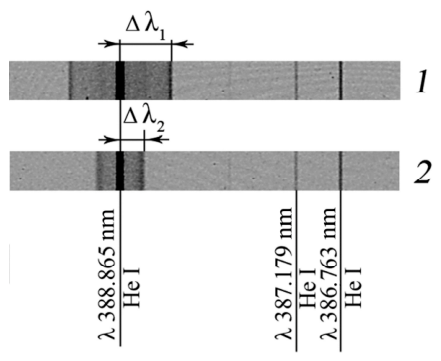
Using an STE-1 spectrograph, spectrograms of helium atoms generated by a flat grid negatively biased to 3 and 0.5 kV were obtained. On both sides of a helium line with wavelength λ = 388.87 nm emitted by slow helium atoms, there are two satellites shifted from the line center at Δλ
1 = 0.48 nm, which are emitted by fast helium atoms moving towards the entrance slit of the spectrograph (on the right of the line) and by those moving in the opposite direction (on the left of the line). Δλ = λv/c is the Doppler shift of the helium line with a wavelength λ = 388.865 nm, where v is the atom velocity and c is the velocity of light (
Figure 9).
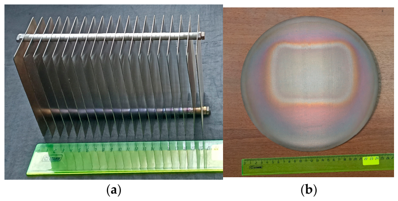
When the grid consists of 20 titanium plates 0.5 mm thick and 175 × 50 mm in size, located at a distance of 10 mm from each other (
Figure 10a), the neutralization of accelerated ions occurs due to contacts with the plates when passing through the gaps between them.
The grid was suspended on the molybdenum rod of high-voltage feedthrough in the center of the chamber. At an argon pressure of 0.06 Pa negative pulses of 5 kV were applied to the grid, and it was bombarded on all sides by 5 keV ions. The beams of fast argon atoms with 5 keV energy generated by the grid etched imprints on steel disks placed on the chamber doors and distant from the grid at 300 mm. The imprint width of 165 mm is 35 mm smaller than the grid width of 200 mm, and their height of 125 mm is 50 mm smaller than the grid height of 175 mm (
Figure 10b). After one of the disks was replaced with an aluminum oxide substrate and the substrate was etched by the same beam, the measured etching rate amounted to ~1 μm/h.
A serious drawback of flat grids used to produce high-energy atom beams is the intense sputtering of their material, which deposits on the chamber walls and any other products within. To solve this problem, the chamber volume is divided by the grid into two parts. An anode placed in one of those parts maintains a glow discharge, and negative potential of the grid of ~100 V prevents electrons from leaving the plasma through the grid into the second part. Increasing the voltage between the chamber and the grid results in a corresponding growth in energy of ions striking workpieces positioned in the second part of the chamber. In this situation only one side of the grid facing the plasma is sputtered, and the deposition rate of its material in the second part of the chamber diminishes by an order of magnitude.
Much better results are obtained when the chamber is divided by a grid composed of parallel plates (
Figure 10a). Only edges of the grid plates are sputtered. The sputtered atoms cannot pass through narrow gaps between the plates and are deposited on them.
3. Results and Discussion
The main distinguishing feature of the gas discharge under study is its low operating gas pressure. This significantly increases the mean free path of ions, allowing them even to pass through the working vacuum chamber without energy loss.
It allowed increasing energy of ions striking a workpiece under nitriding in glow discharge plasma to the highest possible value corresponding to the potential difference between the workpiece and discharge plasma. Due to structural defects induced by high-energy ions in the surface layer, penetration of nitrogen through the surface was facilitated and nitriding rate appreciably increased. Hardened surface layers of AISI 5135 steel with thickness of 100 µm, maximum hardness on the surface ~10 GPa and hardness of the bulk ~3.5 GPa (
Figure 7) were obtained for two hours. It is faster than using a traditional ion nitriding technique by an order of magnitude.
An ion implantation study demonstrated that, in a chamber 50 cm in diameter and 60 cm in length, it is entirely possible to treat a workpiece measuring 4 × 4 × 11 cm3 with 40 keV ions accelerated at a nitrogen pressure of p = 0.05 Pa by high-voltage pulses with an amplitude of 40 kV. This is explained by the fact that the width of the workpiece sheath at 40 kV is approximately 20 cm, while the charge exchange length of 40 keV nitrogen ions at p = 0.05 Pa exceeds 34 cm, and, consequently, the sheath width.
It was found that after processing a workpiece of AISI 321 steel for one hour a 40 µm thick hardened surface layer was produced. The surface hardness
H~13 GPa did not change until the depth of η~20 µm, and only after that it decreased to
H~2 GPa at η~40 µm (
Figure 8). Hence, implantation increased hardness by 6.5 times compared with hardness of the bulk.
The distribution of hardness in the surface layer after implantation (
Figure 8) differs from the smooth decrease in the hardness after nitriding in plasma (
Figure 7). It should be mentioned that in both cases hardening of the surface layer is defined by penetration into the surface of nitrogen atoms assisted by energetic particles.
In the plasma nitriding, penetration depth of fast atoms with energy of 1 keV amounts to several nanometers and each of them produces ~25 displaced atoms near the surface. With the energy increasing to 40 keV the penetration depth and the number of displaced atoms both increase by 40 times and the nitrogen atoms diffuse to the bulk material from a much wider surface layer. It may be the reason for the slow decrease in the hardness until the depth of η~20 μm.
The main difference in the implantation carried out in our work is simultaneous treatment of the whole workpiece surface. There is no scanning, which makes the processing simpler and more convenient.
The second distinguishing feature of the discharge is a high homogeneity of the plasma inside the hollow cathode (
Figure 3). This is achieved through multiple reflections and oscillations of electrons within the cathode, resulting in a uniform spatial distribution of gas ionization.
The distribution of fast electrons oscillating in the chamber can be considered uniform and isotropic. This is evidenced by the even red color of the anode surface and surface of floating electrodes heated with fast electrons (
Figure 4). Those electrodes glow equally regardless of their location and orientation inside the cathode.
Remarkable for this discharge is the appearance of positive anode potential on the anode surface area Sa not exceeding a critical value. It was found that the discharge voltage U is the sum of cathode fall of potential Uc and anode fall of potential Ua. With decreasing gas pressure, the cathode fall keeps a constant value of Uc~500 V and the anode fall Ua rises from ~10 V to 500 V and even higher. Therefore, the power of heating the anode with electrons can account for the majority of the total discharge power.
Experimental melting of 6 mm diameter titanium rods with melting point of 1670 °C showed that a new direction of vacuum metallurgy can be developed. Melting of rod materials can be carried out in any vacuum chamber equipped with a device on the top of the chamber for feeding an anode rod into it.




 ,
,