


Abstract
Among numerous atmospheric-pressure plasma jets (APPJs), high industrial acceptability has been reached for the ones based on high-voltage, low-current, vortex-stabilized arc, typically operated with kHz DC-pulses. This review explores the interrelations between the “process” in a chemical–physical sense and “process”, or to better differentiate, “processing” in the sense of technological treatment, with respect to such APPJs. The mutual dependence of the processing requirements (e.g., high processing speed, compatibility with robotic processing, low total cost of ownership, reliability, and long service intervals) and the physical and chemical processes in the plasma jet are analyzed. The focus is on the hybrid character of the produced plasma, comprising a non-equilibrium arc and a diffuse plasma. Different operation modes of the gliding arc discharge (GAD) are discussed. The reviewed chemical processes are the generation of reactive oxygen–nitrogen species (RONS), oxidation and reduction reactions, and interactions with vapors, solids, and liquids. The considered processing examples are established applications, such as surface activation, cleaning, oxide reduction, film removal, and coating, as well as emerging applications for sterilization and plasma-activated water (PAW) production.
Keywords:
atmospheric pressure plasma jet (APPJ); arc; high-voltage low-current arc; vortex stabilized arc; gliding arc discharge (GAD); forward vortex flow (FVF); cold atmospheric arc; transferred arc; pulsed atmospheric arc (PAA); reactive oxide–nitrogen species (RONS); oxidation; nitriding; evaporation; oxide reduction; surface activation; cleaning; film removal; film sintering; paint removal; coating; cold atmospheric pressure plasma spraying; atmospheric pressure plasma enhanced chemical vapor deposition (AP-PECVD) 1. Introduction
The atmospheric-pressure plasma jet (APPJ) is, in its numerous variations [1,2], a kind of cold atmospheric plasma (CAP) or atmospheric-pressure non-equilibrium plasma (APP) [3,4,5,6,7] broadly used in research and industry. A distinguishing feature of any APPJ is that the plasma, generated within the plasma generator, extends in the open space in the form of a so-called “plasma plume” as far as a few tens of millimeters. The family of APPJs is very large and widely branched. The APPJs can be generated in a broad frequency range. The DC [8], low-frequency (LF) [9], radio-frequency (RF) [10], both capacitive coupled plasma (CCP) [11] and inductively coupled plasma (ICP) [12,13], and microwave APPJs [14,15,16] are used. Numerous APPJ types have limitations that hinder broad industrial application. The RF excitation is limited to 13.56 MHz and its first harmonic to avoid conflicts with the communication channels. It requires bulky matching systems and rigid high-frequency HV cable, especially for higher powers, making robotic applications quite difficult. Also, fixed-frequency 2.45 GHz high-power systems are not compatible with robots, produce hot plasma unsuitable for many applications, and, at high powers, pose a risk of harmful microwave radiation. The microwave APPJ, with frequency matching [17], is limited to low power to avoid electromagnetic compatibility (EMC) issues.
The most widespread type of APPJ [9,18], based on dielectric barrier discharge (DBD), is typically operated with noble gases, thereby increasing operating costs. Devices like plasma needle [19,20,21,22,23] based on 13.56 MHz excitation, kINPen [24,25,26,27,28,29,30,31,32,33,34,35,36] (1.1–1.8 MHz, 2–3 W), and plasma pencil [37] are intended for low power applications.
Another type of power-limited APPJ is based on the needle-to-hole discharge. A plasma jet is generated between a needle-shaped electrode and an orifice-shaped nozzle. The DC version was proposed by Dudek et al. [38] and investigated by Bibinov et al. [39]. The 60 kHz version has been developed by Liu et al. [40]. Toshifuji et al. [41] used pulsed excitation (10–30 kHz) for a similar electrode configuration. The decisive disadvantage of needle-to-hole-based APPJs is the overheating and rapid erosion of the needle tip, which complicates power up-scaling. A power up to 50 W is documented.
The power of recently widely adopted piezoelectric direct discharge (PDD)-based APPJs [42,43,44,45,46,47,48,49,50,51,52,53,54,55] is limited by the technological constraints of the piezoelectric transformer used for plasma generation.
The APPJ, powered by corona discharge, delivers sufficient plasma power for industrial processing. However, this type of discharge is characterized by very low currents. To achieve an acceptable power level, a very high voltage must be used to initiate the discharge. It results in higher dielectric losses in the insulating material used in the plasma generator construction, and consequently in low power efficiency during processing. The corona-type APPJ can be operated over a wide excitation frequency range, from low to radio frequencies. The general tendency is that the corona onset voltage decreases from a few thousand to a few hundred volts, followed by a decrease in the plasma plume length from a few cm to a few mm, with a frequency increasing from a few kHz to 13.56 MHz [56]. At MHz frequencies, the plasma jet becomes homogeneous and steady. The streamers are generated only below 4 MHz.
The large industrial potential of the plasma jet’s available power is in arc-based APPJs. The low-temperature arc jet [57,58] has a high potential for material processing due to its high local plasma density. The popular method of arc stabilization in low-temperature arc jets is a gas vortex [59]. The physical [60], electrical [61], and material [62] properties of such jets are investigated.
Winter et al. [2] proposed a classification scheme for low-temperature APPJs in their review. Although the authors do not consider arc-based APPJs, their classification scheme can be applied to a large extent to define the plasma generator under review. The assignment is as follows:
- The discharge geometry, electrode arrangement, and field configuration; in our case, coaxial electrodes with a central active electrode (cathode, anode, or bipolar-biased) and a grounded nozzle, with no external magnetic field. This classification scheme does not explicitly consider the stabilization of the arc by a gas-flow vortex, which is crucial for the arc discharges under consideration. We propose the assignment of the type of gas vortex flow stabilization to the “discharge geometry”-criterion.
- The type of plasma, which is generated; in our case, the non-thermal, low-current high-voltage (LCHV) arc and its gaseous products (plasma plume).
- The excitation frequency and excitation pattern. In our case, excitation by kHz-power, mostly DC-pulsed but also AC.
- The type of gas or combination of gases injected to the discharge arrangement; in our case, air (synthetic or CDA), nitrogen, nitrogen–hydrogen mixtures, argon–molecular gas mixtures, and other mainly molecular mixtures. In many cases, in parallel to the ionization gas needed for arc generation, the additional gas, vapor, suspension, or mist is introduced either in the arc or into the plasma plume.
Summarizing, the subject of our review is a low-current, high-voltage, forward vortex flow-stabilized arc-based atmospheric-pressure plasma jet, which could be described by an acronym LCHVFVFSA-APPJ). However, to avoid the overgrown acronym, this class of plasma jets will be referred to as ∗JET instead. This acronym also allows for easier referencing of studies using plasma generators from an undisclosed producer while still meeting all the specified ∗JET features. The generic scheme of ∗JET is shown in Figure 1.
Figure 1.
Generic structure of the ∗JET. Arrows depict the direction of gas flow.
APPJs are the subject of many excellent reviews, each with a different point of focus. Depending on the inventor, field of use, and physical characteristics, APPJs are called torches, plasma pens, plasma needles, and so on.
The main focus of the review by Schuetze et al. [10] is the radio-frequency (RF) 13.56 kHz low-temperature APPJ, which is mainly used for etching and coating. A short overview of transferred arcs and plasma torches is also included. It is restricted to high-power, high-temperature, low-voltage arc plasma generators, which are not relevant to our review. Rath and Kar [63] reviewed microwave atmospheric-pressure plasma jets, which could be relevant given examples of devices operating at a similar power level to ∗JETs.
The widely cited review by Laroussi et al. [57] explicitly excludes arc-based APPJs. Lu et al. [1] reviewed APPJ from the point of view of plasma bullet propagation. Since this effect is relevant for noble-gas driven jets, especially helium, the air-based ∗JETs are outside the scope of this review. Also, the review by Woedtke et al. [64], dedicated to plasma for medicine, excludes arc-based solutions. The review written by Reuter et al. [65] describes different versions and applications of the kINPen APPJ, which is not relevant for ∗JETs. Lu et al. [66] reviewed physics and opportunities of APPJs. The authors focused on microdischarge, DBD-driven APPJs, and different pin-to-hole discharges, excluding movable-arc-based APPJs. Also, the review of Corbella et al. [67] does not deal with low-temperature arc sources. Penkov et al. [68] reviewed the APPJs for material processing. Although, at this time, ∗JETs are the most widely accepted plasma generation method for material processing, they are not mentioned in this review. Another review, focused on APPJ applications for surface treatment, by Shang et al. [69], considers the transition to arc as a parasitic effect that should be avoided. No cold arc-type plasma generators are presented.
However, the ∗JETs count in many classifications as part of the family of low-temperature APPJs. Tendero et al. [4] have included in their atmospheric-pressure plasma several arc-based APPJs. Fanelli and Fracassi [58] included, for completeness, examples of arc-based plasma jets successfully used for the surface treatment of polymers and for the deposition of both organic and inorganic thin films in their review. Uricchio and Fanelli [70] reviewed low-temperature atmospheric-pressure plasma processes for the deposition of nanocomposite coatings and acknowledged the application of ∗JET technology for aerosol-assisted plasma deposition (AAPD) and atmospheric-pressure plasma enhanced chemical vapor deposition (AP-PECVD). In summary, a significant gap exists between the perception of ∗JETs in the literature and their highly interesting physics and chemistry, as well as their broad current and potential applicability. In our review, we try to fill this gap.
Clarification is needed for the scope of two terms: “process” and “processing”. On the one hand, “processes” is used for the physical and chemical phenomena occurring in a gaseous discharge [71,72]. On the other hand, it describes a technological procedure that uses plasma to treat materials [73,74]. To avoid the confusion, for the second meaning, the term “processing” [75] is used in this review.
2. Atmospheric-Pressure Arcs
2.1. Thermal Equilibrium
The thermal equilibrium is related to the species present in the plasma. The most important parameter in any kind of plasma is the electron concentration . It is decisive for the generation of other electrically charged particles: positive and negative ions with concentrations and , respectively. To each chemical species present in the plasma, a separate concentration can be assigned. Looking at electric discharge in more detail, any concentration of species x is space- and time-dependent: , which is of importance for the modeling of physical processes (see Section 3.10). Usually used are some aggregated parameters, e.g., the concentration of all electrically neutral particles , or all heavy particles (not electrons) .
Important for classifying atmospheric-pressure arcs is the definition of thermal equilibrium. Plasma is thermal (or in thermal equilibrium) if a common temperature exists for all energy carriers. Typically, such plasma is very hot, with a temperature sufficient for ionization. The typical applications of such plasmas are related to this property. On the contrary, in the plasma in thermal non-equilibrium, each energy carrier has its own temperature, because the energy exchange between different kinds of energy carriers is limited. The temperature of heavy particles replaces the gas temperature but is insufficient to initiate ionization. The most important for the initiation of plasma processes is the electron temperature . At the atomic scale, the equivalent of temperature is the mean energy, given in eV. The energy of 1 eV is J. The temperature corresponding to such energy is 11,600 K. Further temperatures describe the thermodynamic conditions of different excitation states: the temperature of rotational excitation , the temperature of vibrational excitation , and the temperature of electronic excitations .
The ionization and dissociation reactions are governed by the excitation temperature, which can be assumed to be equal to electron temperature . According to Wang et al. [76], for electron densities below 1.0 × , inelastic atomic and molecular collisions are mainly responsible for the ionization of nitrogen molecules since the heavy particles collide more frequently with each other under such conditions and, due to a similar mass, more energy is transferred in each collision than in a collision with an electron. Thereafter, if the rotational energy levels are assumed to be populated by heavy particle collisions, the rotational temperature can be assumed equal to the temperature of heavy particles .
Depending on the discharge parameter, the atmospheric-pressure arc plasma can be either thermal or non-thermal. Provesto et al. [77] used a Langmuir probe to determine the temperature, concentration, and spatial distributions of electrons and ions in the nitrogen, vortex-stabilized DC (150 V, 100 A) plasma jet operated in restrike mode. Already at power as high as 15 kW, they have shown strong thermal non-equilibrium in such a jet. The electron temperature of 11,000 K, compared with the heavy-particle temperature of 6000 K, was measured at the center of the arc.
2.2. Specific Energy Input
The global parameter frequently used for the description of processes in plasma, specifically the energy transfer into the plasma gas with flow rate , is the energy density [78], alternatively called specific energy input (SEI) [79], or beta parameter [80] expressed in J/cm3 or eV/molecule.
where P is the electric power coupled into the discharge. SEI is decisive for the chemical processes in the plasma. In general, the concentration of chemical species produced in plasma increases with SEI. But this dependence need not be linear or monotonic, and it varies with the species considered. According to Expression (1), the physical unit for SEI is J/m−3 (J/liter or J/ccm). To avoid dependence of the gas amount on temperature and pressure, the J/kg can be used. Frequently, to avoid volume variation due to stoichiometry change, the J/mol or kJ/mol is used [81,82]. For easier interpretation of the simulation results, using the eV for ionization, excitation or dissociation energy, eV/mol is usual. Alternatively, the term specific enthalpy in MJ/kg is used [83].
2.3. Thermal Atmospheric Arcs
2.3.1. First DC Arcs
Anders [84] summarized many contributions, especially those of Prof. Vasilii Petrov [85] and Sir Humphry Davy [86], to the first experimentally produced arcs at the beginning of the 19th century, as well as the dispute over scientific priority. In the first phase of DC arc development, the size of the batteries available in the laboratories limited discharge power. The DC arcs of Sir Humphry Davy helped popularize the use of electrical light for illumination. Although it is obsolete for lightning purposes, it is still used as a source of intense UV light. Another branch of DC arc development is the arc furnaces. Today, modern metallurgical DC arc furnaces can reach currents of approximately 100 kA per electrode.
2.3.2. DC Arc Torches
An important application of the thermal DC arc is the plasma torch. The DC arc utilized in the plasma torch can reach very high power levels. For example, Rat et al. [83] describe the application of 100 kW arc plasma torch F4 (Sulzer Metco, Winterthur, Switzerland). The current flow in such torches is high enough to allow for control of the arc by magnetic fields [87]. The magnetic field exerts only a weak influence on low-current arcs. This is one of the criteria used to select the bibliography for our review. Let us take a short glance at the main industrial applications of the hot arc plasma torches: welding, cutting, and plasma spraying [88].
Even though the DC arc plasma torches are mainly used for welding [89] and plasma spray coating [90], numerous applications for material processing are known as well [68]. In the example of the delubrication study by Giannakaris et al. [91], conducted with an argon arc DC plasma torch device Acerios (Fronius International GmbH, Salzburg, Austria), thermally activated decomposition was the dominating process for the carbon-containing contaminants of the lubricant layer, while non-thermal processes were also important for the removal of Na sulfonate component. A similar tool, operated with several different O2/N2 mixtures, was used by Kehrer et al. [92] to improve the adhesion of pressure-sensitive adhesive (PSA) on PP. The best results, better than with primer, were achieved after pure nitrogen jet treatment.
Even though the distinction between high-current/low-voltage and low-current/high-voltage arc-based jets is not sharp, some practical criteria help classify the discharge as thermal or non-thermal. One of them is the intensive erosion of the electrodes, especially the cathode, in thermal arcs. To prevent rapid electrode deterioration in an oxidizing ambient, typically nonoxidizing gases such as Ar or N2 are used. Arcs with currents below 1 A and voltages in the kV range can operate with oxidizing gases (CDA, synthetic air, Ar-O2 gas mixtures, and others).
2.3.3. Plasma Arc Welding and Cutting
The much-cited review by Nemchinsky and Severance [93] provides a brief history of plasma arc cutting (PAC) and presents the current state of understanding of the processes involved. PAC occupies a relatively wide niche between its main competitors: oxy-fuel and laser cutting methods. The cost of PAC equipment lies between very expensive lasers and less expensive oxy-fuel cutting equipment. They address such PAC-specific issues as the dependence of cathode erosion on the rate of current increase, double arcing, and the role of insulating inclusions at the nozzle orifice in double arcing, dross formation, and the shape of the kerf. Colombo et al. [89] discuss the advances in plasma arc cutting technology and the plasma devices used.
Kah et al. [94] discussed the advances in gas metal arc welding. A typical example of a plasma torch for plasma arc welding is the Plasmatron® (Inocon Technologie GmbH, Attnang-Puchheim, Austria) [95,96]. The voltage required to sustain the arc, typically below 100 V, is insufficient to initiate the discharge. In arc welding, this problem is solved by creating a shortcut when touching the grounded welded material (cathode) with the biased anode [97]. In a DC arc torch, it is common to use an extra-low-power, high-voltage plasma igniter. To avoid ignition difficulties caused by oxide films on electrodes, high-frequency igniters are usually used [98,99]. These measures are not needed to ignite low-current, high-voltage arcs because the ignition-gap voltage is sufficiently high. The high power dissipation requires water cooling, which typically makes the torch construction more rigid and bulky than ∗JET. The heavier the plasma torch, the stronger and, consequently, more expensive the robot needed for its fast movement. One of the most critical issues in plasma torch welding is the thermal stress induced in the welded material by the plasma plume.
2.3.4. DC Arc Plasma Spraying
High-temperature plasma spraying is a well-established process for film deposition. Fauchais and Vardelle [100] reviewed their most important applications, including plasma-based processes. Most plasma torches have a single cathode. Their electrical power levels range from 30 to 90 kW. The typical problem with thermal spray guns is aging. The large power density at the arc roots on the cathode tip and the anode wall causes the electrode wear and arc fluctuations, resulting in continuous degradation of the torch performance [101,102]. One method to slow down the aging process is to use multi-cathode and cascaded-nozzle torches. In his review, Maurer [103] presented tri-cathode torches available on the market that can reach over 100 kW. The drift of performance requires the monitoring and control of such devices, which is crucial for most applications. Mauer et al. [104] investigated the methods of monitoring using TriplexPro™-210 (Oerlikon Metco, Wohlen, Switzerland) to achieve process reliability. The problem of the electrode wear also affects ∗JET-based low-temperature plasma-spraying (LTPS), but to a much lesser extent (see Section 3.6).
2.4. Gliding Arc Discharge
The LCHV arc with good prospects for industrial applications is the gliding arc discharge (GAD). It has a long history. The origin of GADs can be traced back to the V-shaped Jacob’s ladder in the early 19th century and later to overvoltage protection in electric networks [105]. A 1988 patent by Lesueur, Czernichowski, and Chapelle [106] describes a knife-edge-type GAD for treating different gas flows.
The highly influential review article by Fridman et al. [107] establishes GAD as a “warm” plasma technology that bridges the gap between thermal and non-thermal plasmas. In the first part of their paper, the physics of gas discharge is described. The second part reviews the chemical reactions in gliding-arc plasma and some possible applications. In the same device, both thermal and non-thermal conditions are possible. Mutaf-Yardimci et al. [108] demonstrated the thermal and non-thermal regimes of gliding arc discharge in air flow. The gliding discharges formed between diverging electrodes in air flow were studied experimentally over a wide range of gas velocities and power levels. It was found that high flow velocities provide intensive cooling, increase the electric field, and decrease the gas temperature, promoting a transition from equilibrium to non-equilibrium at high specific energy input (SEI) levels. Gong et al. [109] reviewed the published GAD geometries for volatile organic compound (VOC) decomposition and distinguished two different electrode geometries, the planar (2D) and the 3D. As examples of 3D GAD, the three-blade and six-blade, and rotating GAD discharges are presented.
Both 2D and 3D GADs can be powered by DC, pulsed DC, or AC. Among the many plasma generation schemas, GAD has a higher electron density (–), which is several orders of magnitude higher than dielectric barrier discharges (–) and corona discharges (–) [82]. It promises higher production rates of the chemical species needed for processing.
In their topical review of non-thermal atmospheric-pressure discharges, Fridman et al. [110] stated that the most promising for large-scale exhaust gas cleaning, pollution control, fuel conversion, hydrogen production, and surface treatment are the discharges, which unite the advantages of thermal and non-thermal plasma systems: the high level of thermal non-equilibrium, high electron temperature, and high electron density.
2.4.1. 2D GADs
To produce 2D GADs, wire- or knife-edge-type electrodes are used. Shiki et al. [111] tested different forms of wire-made electrodes for optimization of the GAD plasma plume shape. Also, Aoqui et al. [112] used steel wires with a diameter of 2 mm as electrodes. Toshifuji et al. [41] generated a GAD between two tungsten wire electrodes (2 mm diameter) with a diverging configuration. To avoid rapid wire wear and overheating, a moderate power of 200 W and pulsed operation were used. To allow for higher power, Kong et al. [113] formed electrodes from bent tubes cooled by water flow. They used the HV generator 9030 E (SOFTAL Electronic GmbH, Hamburg, Germany) with electric output power controlled in the range 400 W to 1400 W in 50 W increments. Also, Kusano et al. [114] used water-cooled electrodes allowing for high-power GAD in thermal non-equilibrium. The GAD can efficiently oxidize the substrate surfaces when the distance from the electrode edge is approximately 6 cm in open air. Czernichowski et al. [115,116] described GADs with the knife-edge-shaped electrodes. Numerous additional examples of 2D GADs with knife-edge-type electrodes are known [82,117]. The advantage of knife-edge-shaped electrodes is improved heat distribution. The heat deposited at the electrode edge, where the arc attaches, can be spread across the large electrode surface and carried away by the gas flow. It enables the operation of the GAD in thermal non-equilibrium at higher power, resulting in higher processing speed/efficiency.
To prevent damage to conductive surfaces during treatment, particularly when the standard gliding arc creates damaging arc spots, Shiki et al. [111] proposed modification of the 2D GAD. They used a plate with a row of holes at the exit of the gliding arc torch, which splits the arc into multiple smaller arcs, thereby reducing the intensity of the arc spots. Such discharge architecture was applied by Ito et al. [118] to sinter the sensitive indium tin oxide (ITO) coating, increasing its conductivity. Nitrogen with 1% hydrogen added was used as GAD plasma for ITO sintering at 160 °C, instead of 300 °C used for conventional sintering.
Ivanov et al. [81] positioned the flat diverging electrodes between a pair of quartz glasses placed on either side of the electrodes so that the gas flow was restricted to the active plasma region between the electrodes. The gas was injected from a nozzle at the closest separation between the electrodes. They reported higher conversion efficiencies with aluminum electrodes than with steel electrodes, attributing this to better heat dissipation in the former. Similar gas flow confinement was used earlier for the cascaded pulsed GAD (see Section 2.4.3).
2.4.2. Pulsed GAD
The application of pulsed HV strongly shifts the plasma properties towards thermal non-equilibrium. In a DC arc, the permanent power supply of energy into the discharge channel sustains high electron and ion concentrations, resulting in high arc conductivity and, consequently, high current and low voltage. When electric power is applied in short pulses, the density of charged particles decays between pulses. Two mechanisms are responsible for this decay. For high initial concentration of charged particles, it is recombination, the speed of which is high and proportional to the product of electron and positive concentrations: . For low and concentrations, the diffusion becomes dominant [119]. The diffusive decay of charged particles, typically expressed in terms of order-of-magnitude estimates, requires many milliseconds. A typical interval between two power pulses is in the range of several tens of microseconds. It means that the discharge channel is refreshed much earlier than it would disappear. The existence of the residual charge particle concentration in the discharge channel between pulses is proven by current flow. Despite the charge presence, the conductivity of such a discharge channel is much lower than for the DC excitation, and consequently, the voltage needed for its refreshing is higher and the current much lower than for DC excitation. It should be noted that pulsed power is a much more power-efficient method for limiting current through an LCHV-arc than, e.g., using an external ballast resistor.
Toshifuji et al. [41] operated the two-wire GAD with pulses at 10 kHz and an additional pulse-width modulation (PWM) of 50% and a frequency of 67 Hz to reduce the power load and wear of the electrodes. It was used to irradiate both the metals and polymers. The gas flow rate reached approximately 500 L/min. Small multi-arcs between the main GAD and the metal surface were photographed.
He et al. [82] improved the energy efficiency of methane conversion in a knife-edge-type GAD by using pulsed excitation. Electrical signal analysis indicates that the arcs can continue gliding with only 1% of the peak voltage during pulse intervals, with the plasma self-sustaining for up to 50 μs. The minimum SEI consumption for hydrogen production of 127 kJ/mol is achieved, which is only 20% of the energy consumption of current mainstream plasma methane reforming.
Differentiating between types of discharge is sometimes not easy. For example, the wide plasma T-jet generator (Tigres GmbH, Marschacht, Germany) is advertised [120] and cited in research studies [121] as a corona discharge. Nevertheless, based on the technical analysis, it appears to be a low-current 2D GAD. A similar gliding arc plasma generator is Blown-Arc [122] (Enercon Industries Corporation, Menomonee Falls, WI, USA). It was successfully used to inhibit in vitro the growth of Fusarium graminearum [123]. However, the same microorganism and its myotoxins were not sufficiently reduced by the postharvest Blown-Arc plasma treatment on the field-infested wheat grain [124].
2.4.3. Cascaded Pulsed GAD
The advantages of the pulsed 2D GAD are implemented in the cascaded pulsed 2D GAD developed and investigated by Roig [125]. Since this study is not published in any journal, some interesting results are presented. A series of single GAD (discharge cascade) can be ignited if the voltage delivered by the HV power supply is high enough and the smallest gap between electrodes is small enough. Figure 2 shows a cascade of five GAD discharges, where only the left and right outermost electrodes are HV-biased and grounded, respectively. The flat electrodes are sandwiched between the PEEK back plate and the front quartz glass plate, enabling visual observation of discharge development. The single GADs start in the five narrow gaps at the bottom of the photograph (the bright spots near the bottom line) and are blown upward. The exposure time 1 ms of the photograph shown is long enough to capture the 54 current pulses of the 54 kHz excitation. Each line in the GAD picture corresponds to a short period of high current flow through the arc. Between the light lines, the current is much lower, resulting in dark areas in the photograph. Reaching the top position and the largest length extension, the arcs should get disrupted, and the life-cycle of the discharge should repeat, like in the standard 2D GAD described in the previous section; however, the 1 ms exposure time is not long enough to capture the entire life-cycle of the GAD. To investigate it in more detail, a high-speed camera is used.
Figure 2.
Five linearly arranged gliding arcs, powered by a single high-voltage, 54 kHz power supply. The plate electrodes, shaped as rounded triangles, are fixed between two plates, the back one made of PEEK, the front one of quartz glass. An air flow of 60 SLM is blown in from the bottom. The photograph was taken with Canon EOS 5D, 12.8 Mpx with the aperture 5.6 and exposure time 1 ms [125].
The process of the temporal development of seven parallel GADs is illustrated in Figure 3. Four high-speed pictures are shown and correlated with the voltage measured at the HV electrode. Picture (1) is captured 0.1 ms after arc ignition. The voltage collapses from 8 kV to about 1.5 kV, and the first luminous phenomena appear. Then, the arcs are caught by the air current and pulled upwards to the exit. Meanwhile, these arcs become increasingly longer. This can be seen from numbers (2) and (3), 0.5 and 1.4 ms after arc ignition, respectively. A higher voltage is needed to maintain the arcs. It increases and reaches about 11 kV in phase (4), about 1.9 ms after arc ignition. Finally, the arc is blown out of the zone between plates and extinguishes. The next ignition follows, and the process begins anew. The differences in the speed at which the arcs are expelled cause the asymmetry seen in the images. The uneven distribution of gas flow among the seven channels is responsible for this effect. Further observation is that the right arc feet are generally brighter and broader than the left ones. Since the HV pulses are positive, the cathodic arc spots exhibit higher energy deposition. This effect was also observed in the single 2D GAD and documented by Korolev et al. [126]. The motivation for the presented research was the large-area treatment of polymers. Good activation results were achieved. The main obstacle to industrial implementation was the much greater electrode erosion than in ∗JET. A plausible reason is the need for frequent arc ignition at 2 ms intervals, which requires a high voltage to achieve high power density in the narrow gap. In contrast, the HV arc once ignited in ∗JET remains ignited and needs only to be sustained at much lower voltage, typically below 2 kV (see Section 2.4.5).
Figure 3.
The sequence of four high-speed pictures of seven linearly arranged gliding arcs, powered by a single high-voltage, 54 kHz power supply. The plate trapezoidal electrodes, are fixed between two plates, the back one made of PEEK, the front one of quartz glass. The voltage is applied between the leftmost and rightmost electrodes. An air flow of 60 SLM is blown in from the bottom. Pictures were taken with a high-speed camera pco.dimax HD with 2.1 Mpx sensor. (1) 0.1 ms, (2) 0.5 ms, (3) 1.4 ms, and (4) 1.9 ms after start of arc ignition [125].
2.4.4. 3D GADs
The first idea when considering a 3D GAD structure is to place more than two non-coplanar electrodes in the gas stream. Stryczewska and Komarzyniec [127,128] addressed this task by arranging several GAD electrodes around a common axis, along which the gas flows, and DC biasing them synchronously. They characterized the electric properties of the GAD with three knife-type electrodes. The GAD generated by six-knife blade electrodes was presented by Baba et al. [129].
A nonconventional electrode configuration was implemented by Czernichowski et al. [130] in the GAD reactor called GlidArc-II. The rotation of the blade-shaped, serrated electrode extended the length of the arcs. The idea was to improve energy efficiency in converting the flowing gas.
2.4.5. Forward Vortex Flow GAD
The GlidArc-III reformer [131] was the further development of GlidArc-II, working with forward vortex flow (FVF) of the arc. The characteristic feature of the forward vortex flow (FVF) GAD is the rotating arc extending in the direction of the gas flow. In general, a non-equilibrium rotating GADs shows 3 times higher efficiency than thermal ones [107].
Petitpas et al. [132] characterized the electric parameter of an air arc dedicated to reform different hydrocarbons with the addition of steam. They measured the increase in the power dissipated during discharge with the discharge chamber pressure, about 20% for a 2.5 bar increase. This method of increasing power is limited by arc-stability requirements, which are less stringent at lower pressures. Petitpas and Fulcheri [133] analyzed existing arc models, primarily developed for high-current, low-voltage arcs, to assess their applicability to low-current, high-voltage arcs. They discussed the correlations with the experimental results.
Kim et al. [134] characterized the arc position in an FVF GAD reactor. They proposed four modes to describe the behavior of the arc in such a discharge, which is frequently cited in other studies.
- I.
- An arc ignites along the shortest path between the anode and cathode and rotates (or not) there, because the vortex flow is too weak to transfer it further.
- II.
- A gliding arc rapidly extends along a spiral trajectory from the closest gap between the electrodes to the tip of the conical high-voltage electrode, where the arc is disrupted, and the process repeats.
- III.
- The arc is anchored between the tip of the high-voltage electrode and the nozzle throat, resulting in a constant arc column length.
- IV.
- It can be seen as a high-SEI condition, where the arc is developed beyond the nozzle throat or driven out of it.
This mode classification can also be applied to the vortex-stabilized ∗JETs. Mode I is valid during the phase of arc ignition or insufficient gas flow. Mode II can be used to describe the transfer of the arc root to the stable rotation trajectory. Mode III refers to the condition equivalent to the operation of the ∗JET nozzle when the rotation trajectory of the arc remains within the nozzle, as shown in Figure 4. Mode IV is established when the trajectory of arc rotation is pushed out of the nozzle orifice, as shown in Figure 4. This four-mode classification does not distinguish between an arc rotating around the grounded nozzle and an arc transferred to a grounded substrate, even though both have constant arc length. To cover the behavior of the arc extruded out of the ∗JETs and transferred on a grounded substrate, we have added the fifth mode.
Figure 4.
FVF GAD modes applied to the ∗JET. (I) arc ignites along the shortest path between the anode and cathode and rotates there, (II) arc root shifts downwards with the gas flow and is disrupted to be ignited again, (III) establishing the arc FVF-driven rotation within the nozzle and generating the plasma plume, (IV) establishing the arc rotation outside the nozzle and generating the plasma plume, and (V) the arc is transferred onto the grounded substrate, generating diffuse plasma at the substrate surface.
- V.
- The main differences between this arc mode and mode IV are that the arc does not bend back to the nozzle or torch wall, and that it is attached to the grounded substrate outside the torch and rotates there, or not. The diffuse plasma is produced at the substrate surface.
2.4.6. Reverse Vortex Flow GAD
The generic GAD plasmatron with RVF was developed at Drexel Plasma Institute and patented by Rabinovich et al. [135]. In this DC-powered plasma reactor, the large-diameter upward vortex and the small-diameter downward vortex are established. The gas enters through tangential inlets on the side, propels the larger vortex, flows into the reactor volume, and then exits through the anode [131]. The arc is stabilized within the downward inner vortex and rotates at the bottom-mounted anode. The axial hollow in the top-placed cathode forces the cathodic arc foot onto a circular trajectory, minimizing erosion of the cathode material.
Kalra et al. [136,137] studied RVF GAD, also called the gliding arc “tornado” (GAT). In the intermediate development stage, it was equipped with a spiral electrode to guide the arc gliding movement. However, experiments show that, in the presence of RVF, a simple ring electrode is sufficient to establish the vortex-stabilized arc. The RVF GAD is especially suitable for use as a chemical reactor. In contrast to forward-vortex-flow GADs, it provides much more uniform gas treatment and a significantly longer gas residence time in the reactor. It allows for a stable operation regime when the variation in GAT current is very small. The research group PLASMANT of Annemie Bogaerts was strongly involved in the research on this type of GAD [138,139,140].
2.4.7. Gliding Arc Discharge APPJ
Suitable to work as ∗JETs are FVF GADs operated in mode III, IV, or V (see the definition in Section 2.4.5). The ∗JETs stabilized by a gas-flow vortex share some features with such GADs. Before vortex stabilization is developed, the HVLCA is driven directly after ignition by gas flow from the ignition point to the nozzle outlet (see Figure 4), much like a typical FVF GAD. The similarity is especially apparent when considering a GAD powered by kHz pulses, as in the study by Shiki et al. [111]. They used 20 kHz pulses with a 2 μs width at an input power of 300 W to generate a GAD for the surface treatment of conductive materials.
Dinh et al. [141] developed a novel modification of the FVF GAD jet for dry reforming. An AC plasma power supply with high voltage (several kV), low current (several A), and a frequency of 20 kHz is adopted to generate non-thermal arcs in mode III. It is a nozzle-type reactor in which the nozzle serves as the grounded electrode, showing strong similarity to ∗JETs.
Dinh et al. [142] continued the work on this reactor. They conducted a comparative study of this novel FVF GAD reactor with a standard one [143]. The reactor with a narrow nozzle exhibits much better conversion performance than the reactor with a large nozzle opening. At SEI of 5 kJ/L, the and conversions in the nozzle-type reactor were 74% and 49%, respectively, while they were only 40% and 28%, respectively, in the conventional reactor. The thermal analysis of both reactors explains this difference.
Chalise et al. [144] presented a 2D-GAD-based APPJ. They showed an increase in the diffuse plasma plume, with the GAD airflow rate increasing from 5 to 17 L per minute. This increase in jet length is correlated with increases in the RMS voltage between the GAD electrodes and in the power deposited in the discharge. The electron excitation temperature was determined from OES measurements collected in the plasma plume. It ranges from 15,800 to 16,700 K (1.36 to 1.44 eV), increases with the applied voltage, and decreases with the flow rate. Consequently, the luminosity of the plasma plume behaves similarly.
Korolev et al. [145] investigated the generation of the APPJ from a plasma device labeled “plasmatron”. It is a DC-GAD plasma generator with coaxial electrodes. The inner electrode of the plasmatron is the cathode. The grounded nozzle, consisting of two sections, serves as the anode. The low-current discharge is sustained in a vortex airflow with a mass flow rate of 0.1 to 0.5 g/s. The inner electrode of the plasmatron is the cathode, and the grounded nozzle serves as the anode. The nozzle diameter was and the length of each section was 5 mm. The distance between the section can be varied from (when the sections are connected) to m. The discharge is powered by a DC voltage of 3 to 5 kV, connected to the electrodes via the ballast resistor and a coaxial cable. In the setup under description, the cathode diameter is 9 mm and the minimal gap distance between the electrodes in the coaxial part of the electrode system amounts to 1.5 mm. Under such conditions, the voltage is insufficient to cause the first breakdown and initiate the discharge in the plasmatron. To initiate the discharge, an additional pulsed power supply with an amplitude of up to 15 kV and a pulse duration of 4 μs was applied.
The GAD-based APPJs are frequently used to treat the biological material. Doria et al. [146,147] operated the FVF GAD in mode IV with voltage pulses at 60 Hz. They used it to inactivate Candida albicans biofilms. Chiappim et al. [148] used a circular vortex GAD to investigate the antimicrobial effect of plasma-activated tap water on Staphylococcus aureus, Escherichia coli, and Candida albicans. Many types of discharges, including GAD, are tested for grain treatment. Chiappim et al. [149] used a circular vortex GAD plasma jet on the mycobiota and deoxynivalenol levels in naturally contaminated barley grains.
2.5. Low-Current High-Voltage Arc Atmospheric-Pressure Plasma Jet
The breakthrough of the industrial application of ∗JETs is the invention by Peter Förnsel [150] in the Agrodyn Hochspannungstechnik GmbH (later transferred to Plasmatreat GmbH). The plasma generated by ∗JET can be considered a hybrid plasma, according to the definition proposed by Fridman et al. [107] in their monography about GAD and by Kusano [75] in his review of atmospheric-pressure plasma processing for polymer adhesion. This hybrid character can be interpreted as the coexistence of the hot plasma in the arc itself and cold plasma in the plasma plume. Both the thermal and non-thermal components of the discharge can be applied for material processing. Meanwhile, many producers offer generators of such plasmas which can be classified as ∗JET. In Table 1, a selection of such generators and producers is listed that have been cited in the scientific or technical literature. In the first column, the abbreviations of the plasma generators are defined to be used throughout this review.
Table 1.
The ∗JETs referred in this review.
Different technical measures can reduce the thermal load originating from the arc: (i) the gas flow blows the arc out of the zone between the electrodes, (ii) vortex stabilization is used to extend the arc length and consequently, to increase its resistance and to limit the current, (iii) the power is supplied in short pulses of a few μs and frequencies in the kHz range, being sufficient to sustain the discharge, but reducing the mean power strongly and, consequently, the thermal load of the discharge channel, and (iv) voltage of about 2 kV per 1 mm of the ignition gap is applied only for discharge breakdown, and reduced to hundreds of V for continuous operation. Due to the still-high power of such discharges, many hundreds of watts to a few kW, this type of discharge is suitable for thermally sensitive substrates only if they are exposed to such plasma for a short time (see Section 4.1). Crucial for the development of a ∗JET-based processing is the balance between thermal load and treatment efficiency. Since both increase with surface power density, the process parameter window for ∗JET treatment is typically quite narrow.
The ∗JETs cover a fairly broad power range. It is not certain whether P-Pen meets all ∗JET criteria, such as vortex and pulsed energy. However, it is operated with air and at a power level (150 W) which is still acceptable for this classification. On the other hand, devices with much higher power are considered. The company Atmospheric Plasma Solutions, Inc., developed a portable atmospheric plasma coating removal (APCR) system, PB-7000 M. Yancey et al. [168] described its development. The maximum power of this ∗JET is 2000 W, and the typical speed for film removal is 170 mm/s. Also, PB3, equipped with two PS2000OEM units, operates with 2000 W.
An important parameter that can typically be set in ∗JETs is the HV frequency. In OpenAir, it is in the range from 15 to 25 kHz. In PB3, the pulse frequency can be set to 40–65 kHz. AcXys-ULS uses an even higher frequency. Brès et al. [191] characterized this device for the electrical diagnostics. The resonant power supply generates a sinusoidal voltage between the inner electrode and the grounded nozzle, with a frequency range of 80 to 200 kHz.
Since the authors gained most of their experience with ∗JET-technology using the PB3 (see Table 1), this system is frequently cited in this review as an example, following the generic scheme in Figure 1. PB3 uses the plasma generator PG31 [154] to produce the plasma plume. Its cross-section is shown, and its operation principle is explained in [155]. The arc required for plasma generation is sustained between the positively biased inner electrode (anode) and the outer edge of the grounded plasma nozzle (cathode) by HV pulses supplied by the power supply PS2000 OEM [192], connected via a 10 m coaxial HV cable to the plasma generator. The relative power level can be set as a percentage when the total electric power consumption is approximately 1 kW. The mean values of voltage, current, and power are measured internally at HV output and are available over the CANopen interface. After arc ignition at a voltage in the range of 15 kV, the power is controlled, resulting in an operating voltage between 500 and 3000 V, depending on operating conditions (gas type, gas pressure, gas temperature, and frequency). The forward vortex flow of ionization gas is stabilizing the HV arc along the axis of the plasma generator. The PG31 is equipped with different nozzles. The one most frequently used, working in mode IV or V, is the A450 [193]. It is made of copper. The diameter of its gas outlet orifice is 4.2 mm.
An interesting variation in APPJ based on high-voltage, low-current discharge uses a spark instead of an arc [194,195,196]. The active electrode is typically pin-shaped [197]. It is powered by DC with a ballast resistor [198], kHz-DC-pulsed type [195], ns-pulses [199], or kHz-AC [40,200]. The main difference compared to ∗JETs is a comparatively low operation power in the range from a few watts [201,202] to tens of watts [203] and no use of vortex stabilization or gliding arc. Considering these differences, they are not treated systematically in our review.
Due to their increasing popularity and different mechanical design, the rotation nozzles are considered separately in Section 4.2.3.
3. Processes in ∗JETs
3.1. Structure of the ∗JET Plasma
3.1.1. Diffuse Plasma
The classification in Figure 4 should be supplemented by addressing the hybrid character of ∗JETs. Typical for the plasma generators covered by this review is the coexistence of the arc discharge with the diffuse plasma consisting of the products of interaction between the arc and the gas flowing through it. When the charged particles are confined by electrostatic forces in the core of the arc, neutral particles can freely enter and leave the arc zone, driven by thermodynamic forces. This phenomenon is why the diffuse plasma contains mainly electrically neutral species. However, during the dwell time in the arc, neutral particles can be energized by interactions with electrons and photons, resulting in electronically, vibrationally, and rotationally excited species and atomic and molecular radicals, which can transfer the accumulated energy to the substrate surface [155].
Depending on the length of the arcs relative to the nozzle length, the plasma plume can be purely diffusive (mode III) or consist of both extruding arcs and a diffusive zone (mode IV). Let us consider an example of the mode III operation, when the arc does not extend beyond the nozzle exit. Figure 5a shows the cross-section of the nozzle of the PB2 made of aluminum [204]. In the bottom half of the nozzle, an inserted metal cylinder made of erosion-resistant material is visible. Under typical operating conditions, the arc foot rotates within this cylinder. However, at excessive voltage and flow or at a strongly eroded insert, the arc feet reach the aluminum nozzle throat. The arc foot causes the local melting and rapid oxidation of the aluminum, resulting in dark spots. Even though aluminum oxide (Al2O5) is white, small amounts of alloying additives cause it to turn black. In the excerpt depicted with the rectangle in Figure 5a and shown in magnification in Figure 5b, these spots are clearly visible. The positions of the arc’s docking points on the nozzle’s inner wall depend on the length of the arc blown from the ignition zone. They are statistically distributed. On the left side of the magnification, the continuous layer of oxidized material can be seen. As the gas moves downstream, the interaction between the arc and the aluminum surface becomes less and less likely. The islands become smaller and finally disappear. If the nozzle is long enough, the arcs are trapped within it. Close to the nozzle exit, almost no oxide is observed. In such a case, the plasma plume visible outside the nozzle exit is entirely diffuse. If the segment of the nozzle throat without arcs is long enough, the electromagnetic field produced by arcs is sufficiently damped to consider such a nozzle as potential-free.
Figure 5.
Picture of the halved nozzle of PB2 made of aluminum. (a) Two halves of the nozzle with the stainless-steel sleeve, and (b) the microscopic magnification of the arc docking transition region depicted with yelow rectangle in (a). Internal report of Reinhausen Plasma GmbH [204].
3.1.2. Influence of Nozzle Shape on Plasma Plume
The construction of the nozzle, especially the length and diameter of the nozzle throat, and the operation conditions, such as gas flow, type, and arc discharge voltage, determine if the ∗JET operates in modes III, IV, and V (see Figure 4). For low gas flows and/or power, the arc remains trapped within the nozzle and rotates around the inner wall of the nozzle throat (mode III). For higher voltage and/or/and gas flow, the drag of the gas vortex shifts the arc foot out of the nozzle throat, causing it to move around the nozzle lip (mode IV).
The nozzle shape is decisive for the position of the transition between the arc zone and the diffuse plasma zone. If this transition is within the nozzle, the ∗JET operates in mode III. If this transition occurs out of the nozzle, the ∗JET operates in mode IV. Especially important for the location of these transitions is the length of the throat nozzle part. Szulc [205] investigated the influence of the length of the throat part of the nozzle discharge cavity on the properties of the plasma plume. The diameter of the throat for the three investigated nozzles was 4 mm. He used the PB3 system to generate plasma. Only for a short throat of 5 mm did the arcs protrude from the throat and contribute significantly to the thermal load. For the throat length of 15 mm and 25 mm, the arc remained within the throat, and only diffused plasma was seen outside the nozzle. This observation was valid across the entire investigated gas-flow range of 30 to 60 SLM. The length of the diffuse plasma plume increases with gas flow and throat length. The elongation with throat length is justified by increasing the arc length and consequently the power deposited in the arc. These results have laid the foundation for the development of the PB3’s cold [206], medium [207], and hot [193] nozzles.
Similar results were obtained by Kewitz et al. [208] with the PFW-10 nozzle of OpenAir (FG 5005 with a HTR 11 transformer). They used the passive calorimetric probe [209] to measure the energy flux of the plasma plume at a constant distance from the nozzle orifice for two different nozzle designs. The first design is a standard PFW-10 with an orifice diameter of 5 mm and a short throat. The second one has a relaxation volume extending the throat length by about 16 mm. The energy flux measured at the same distance from the nozzle edge is much lower for the long-throat nozzle. For nitrogen flow of 29 SLM, mean voltage of 400 V, and distance of 4 mm, the energy flux for the short-throat nozzle of 470 W·cm−2 is by a factor of ca. 2.5 higher than for the long-throat nozzle. They also observed a strong decrease in the energy flux with increasing gas flow rate for the long-throat nozzle, but only a weak decrease for the short-throat nozzle.
3.1.3. Hybrid Plasma Plume
For short nozzle throat, high arc voltage and gas flow, the ∗JETs operate in mode IV, and arcs protrude from the nozzle opening. In such a case, the plasma plume consists of two zones, the hot arc zone and the diffuse zone.
A frequency of the HV pulses in the range of tens of kHz is high enough to avoid complete arc extinction between two pulses. The discharge channel remaining along the arc current trace is much easier to reignite than the non-pre-ionized air gap. When taking photographs with a longer exposure time, instead of a single arc, an arc overlap at many subsequent positions can be seen. The fast, rotational motion of the arc results in a characteristic filamentary, bright primary plasma observed at the nozzle orifice during plasma jet operation [155]. The arc foot rotation speed reaches a couple of thousand rotations per second. During one rotation cycle, 10–100 current pulses sustain the arc. The protruding arcs can be used directly for surface treatments, but they can also be used to process materials other than surfaces. This is the case, e.g., when gases, suspensions, or powders are injected directly into the arc zone.
3.1.4. Transferred Arc
The HV arcs, which, in operation mode IV, end at the nozzle lip, can transfer to the metallic substrate. If the ∗JET is approaching an electrically non-conducting substrate, the diffuse plasma is spreading on the substrate surface, but the path of the arcs is principally not changing (operation mode IV). This also applies to electrically conducting substrates that are not grounded. To reach the transferring the arc to the substrate (operation mode V in Figure 4), the substrate must be grounded.
The transition from diffuse plasma to transferred-arc operation mode is not abrupt [155]. As the distance between the substrate surface and the nozzle decreases, the number of arcs ending on the substrate rather than on the nozzle lip increases gradually. The distance at which the arc starts to transfer from time to time to the substrate (limit of the mode IV) and the distance at which the arc ends permanently at the nozzle lip (complete arc transfer-mode V) have been determined for nitrogen/hydrogen gas mixtures and are displayed as a function of hydrogen percentage in Figure 6. The upper line in the diagram represents the transition to mode IV without arc transfer. The bottom line represents the transition to the purely transferred arc mode V. The gap between the start and completion of the transfer distance is approximately 3 mm.
Figure 6.
The distance between the nozzle tip and the grounded surface at which the transition between the non-transferred (mode IV) and transferred arc (mode V) operation occurs, displayed as a function of hydrogen percentage in the nitrogen/hydrogen gas mixture. The red bullets and green triangles show the experimentally determined lower limit of mode IV and upper limit of mode V, respecitvely. These results are determined for PB3 with nozzle A450 operated with an HV pulse frequency of 65 kHz and a total gas flow of 60 SLM [155].
The arc-foot irregular movement is restricted to a small circular area on the substrate. At a larger distance from the nozzle mouth, the rotational component of gas movement is too weak to force the rotation of the arc-foot. Since the power deposition at the substrate surface is confined to a small spot, this type of plasma is frequently called a focused plasma. Since the temperature in the focused plasma is much higher than in the diffuse plasma, reaching several thousand K, physical and chemical processes typical of such high temperatures can be initiated (melting, evaporation, thermal decomposition, and so on). This opens the processing options, which are not available in the diffuse plasma of a ∗JET. If the transferred arc is used for surface treatment, typically the motion speed of the ∗JET is much higher and the distance between the nozzle tip and the surface much closer than in the case of diffused plasma treatment. An example of a successful application is the pretreatment of a thin aluminum foil at speeds up to 12 m/s [210]. Depending on the polarity of power pulses supplied to the active electrode, the foot of the transferred arc has anodic or cathodic character. Due to high power density at the substrate surface, the transferred arc is especially suitable for the so-called cathodic cleaning [211] of the grounded substrates.
An additional advantage of the transferred arc is that no erosion of the nozzle occurs, and consequently, the lifetime of the nozzle can be prolonged by an order of magnitude [210]. Along the arcs, a high potential gradient can be measured. It limits the applicability of operation mode V for treating electrically sensitive objects, such as IC chips or PCBs populated with electronic components.
For some thermally sensitive substrates, the mode V of ∗jet operation was described as a parasitic effect. During the treatment of carbon fiber, Pitto et al. [212] observed the diffuse and filamentary (arc) plasma. Since the carbon fiber is electrically conductive and grounded over the movement mechanisms, operation mode V in P-Tec ∗JET was observed. Using a high-speed camera with long exposure, a picture of the field of view was taken, depicting the 10 mm nozzle–substrate gap. They observed the transition from the diffuse to the filamentary mode as the gas flow rate increased from 23 SLM to 33 SLM. This is plausible, since the length of the blown arc is increasing with the gas speed. The filamentary mode caused damage to the tow. It was avoided and, in most cases, not characterized.
3.1.5. Plasma Bridge
The applicability of the operation mode V is restricted to the metallic substrates with electrical grounding. In some cases, wiring substrates to ground is not possible, e.g., if the pads on electronic boards are designed to be electrically floating. The study of Korzec et al. [156] demonstrates how an electrically floating surface charged up by a transferred arc can be grounded using a plasma bridge. Originally, the term plasma bridge referred to the low-pressure plasma used for neutralization of an ion beam [213]. In the context of APPJ operation, it means the gaseous discharge ignited at atmospheric pressure in a low-breakdown-voltage gas, such as argon, to establish a highly conductive electrical connection between the substrate and the grounded gas injector (see Figure 7). The plasma bridge is ignited because, without grounding, the potential of the electrically floating substrate rises to many hundreds of volts, sufficient for gaseous breakdown in argon between the substrate and the grounded injector. After ignition, the plasma bridge can be sustained even in the absence of a substrate between the injector and the HV arc.
Figure 7.
The transferred arc plasma generated by PB3 in forming gas 95/5 with a flow rate of 60 SLM and the plasma bridge ignited in argon (flow rate: 5 SLM), short-cutting the substrate with the grounded injector. The HV pulse frequency was 62 kHz, and the distance between the nozzle and the substrate 6.5 mm [156].
The initiation of the plasma bridge is possible for argon flows between 3 and 10 SLM. The plasma bridge cannot be sustained with argon flow below 3 SLM. At such low flows, the argon flux is insufficient to reach the substrate and close the electric gap between the biased substrate and the injector. The plasma bridge cannot be sustained for argon flow over 10 SLM, either. The possible reason is the transition of the argon flow from laminar to turbulent, disrupting the argon bridge discharge. The plasma bridge current was measured. Between 3 and 10 SLM, it remains almost constantly 350 mA. It can be explained by the current-limiting effect of the HV arc, which has much higher impedance than the plasma bridge. Figure 7 shows the picture of the transferred arc in forming gas 95/5 and the argon plasma bridge focused on the surface of the electrically floating metal plate, taken with a long exposure time. The color difference between the focused plasma (bluish) and the plasma bridge (orange) is apparent. The plasma bridge, once ignited on the conducting substrate, does not extinguish immediately when the substrate is removed but, for some time, remains connected to the HV arc discharge, forming a closed current loop.
3.2. Plasma Plume Thermal Characteristics
3.2.1. Temperature
The thermal characterization of the plasma plume can be performed by measuring temperature profiles with a temperature sensor. Figure 8a shows the axial and Figure 8b the radial distributions of statically measured temperature. To prevent the transfer of arcs to the temperature sensor, it was inserted into a thin alumina tube. The sensor was moved through the plasma plume using an XYZ robot.
Figure 8.
Temperature distribution measured with a temperature sensor statically in the plasma plume of PB3 operated with three different nozzles. (a) Axial and (b) radial distributions. Other parameters: CDA, 50 SLM, 54 kHz. Internal report of relyon plasma GmbH.
3.2.2. Energy Flux
The static temperature is not sufficient to estimate the thermal load of fast-moving substrates. For such calculations, the energy flux in W/cm2 is more useful. Fröhlich et al. [214] used a calorimetric probe to characterize the spatially resolved energy flux in the plume of the OpenAir (FG 5001 in combination with an HTR 12 transformer and a PFW 10 nozzle). The OpenAir was powered by rectangular voltage pulses at 17 to 25 kHz, with a power of 3 kW and a 29 SLM. Nitrogen, oxygen or dry air, respectively, has been used as a process gas. As the distance from the nozzle increased from 15 to 40 mm, the energy influx decreased from about 90 to 20 W/cm2. The injection of nitrogen resulted in a higher energy influx in comparison to oxygen and air, presumably caused by higher formation and recombination energy in the case of . The smallest energy influx was measured for oxygen.
Kewitz et al. [209] investigated OpenAir in a similar setup, using an RD 1004 nozzle and a newly designed calorimetric probe. The energy flux increases almost linearly with the applied primary power. It decreases with distance, inversely proportional to the distance, from about 300 W/cm2 at 4 mm to 100 W/cm2 at 20 mm, and increases slightly with gas flow. The 2D mapping of the energy density measured in the plane perpendicular to the plasma plume axis exhibits a high rotational symmetry. The main heat flux is observed within a diameter of 10 mm.
They continued [215] their analysis of passive calorimetric probe measurements at high energy influxes on OpenAir (FG5001 generator, an HTR12 transformer, and an RD1004 nozzle). The metallic probe directly contacting the thermocouple restricts its use to the diffused plasma jet only, since arcs transferred to this electrode would cause electrical disturbances to the measurement.
3.2.3. Temperature Measurement by OES
The temperature sensors or calorimetric probes disturb the plasma plume thermally, aerodynamically, and electrically, and consequently, affect the measured temperature profiles. Long-term measurements cause deposits to grow on the probe surfaces, falsifying the measurement results. These problems inspired the search for contactless measurement of plume temperature. One of the contactless methods used for determining plasma temperatures is OES.
Kubota et al. [216] performed OES spectroscopy of the inside of a jet nozzle through a quartz window in the OpenAir-body (PFW10 system) and along the plasma jet nitrogen plume. They estimated the rotational temperature by fitting the measured bands with calculated ones (second positive system). It is approximately 5000 °K in the arc inside the plasma generator, and 4000 °K just out of the nozzle mouth. In the plasma plume, temperature decreases with distance from the nozzle, reaching 1000 °K at 100 mm.
Ni et al. [217] used the OES to determine the vibrational temperature in the plasma plume of an AC-driven ∗JET at power below 1 kW. It is much higher than the gas temperature, indicating that the AC-driven arc discharge deviates from thermal equilibrium plasma. Chernyak et al. [218] monitored the optical spectrum from 200 to 1100 nm emitted by the air jet plasma from the transverse arc discharge. This discharge differs from the non-stationary gliding arc of Czernichowski type [115] by the fixed arc length. Since the current and voltage of this arc, typically 200 mA and 1.2 kV, respectively, are similar to the ∗JET operation conditions, it is relevant for our review. It also has convective cooling of the plasma column by airflow, but no conductive heat losses to the walls, since it is a free arc jet. They identified all notable emissions from excited atomic lines of N, O, and H, as well as molecular bands of NO, , , OH, CO, and CN. One of the main points concerns the mechanism of the transition from quasi-equilibrium to the non-equilibrium arc, i.e., from thermal to non-thermal ionization. The results presented allowed the authors to conclude that there is no local thermal equilibrium (LTE) in this arc-discharge air plasma over its space–time evolution. The characteristic temperatures within a relation , for electrons, electronic excitation of free atoms, vibrational, and rotational excitations of molecules, and for heavy particles, respectively, are measured/estimated. The and along the flow are 7000–8000 K and 4000–4600 K, respectively. The differs from and more than twice. Therefore, a conventional two-temperature approach with for electrons and for gas components is not sufficient to describe this type of discharge. Another characteristic effect is an “ignition” of the plasma luminescence downstream of the arc discharge, resulting from the kinetic non-equilibrium conditions. The highest value is measured in the center of the arc. In the afterglow zone, decreases rapidly while and keep their high values longer. Similar values of rotational temperature in the nitrogen plasma plume of the PB3 ∗JET in the range of 3940 ± 70 K and 4070 ± 70 K for the different gas flows were determined by Mrotzek et al. [219] based on the optical emission spectroscopy in the wavelength range from 200 to 960 nm.
Szulc et al. [220] evaluated the nitrogen molecular spectra measured in the arc zone of PB3 operated in mode IV with A450 nozzle at 60 kHz. They determined a heavy particle temperature of about 6500 K by fitting synthetic spectra to the second positive system of molecular nitrogen () with the band head at 337.13 nm and first negative system of the nitrogen molecular ion () with the band head at 391.44 nm. This temperature decreases slightly with radius and strongly with distance from the nozzle beyond 4 mm. The position of this drop correlates with leaving the arc zone. For comparison, the temperatures detemined on the base of the same transitions in arc produced in RVF are are 5500 K and 6200 K, respectively [221]. The same researcher [222] measured, using the same ∗JET and similar setup, the Stark broadening and determined the electron temperature of about 40,000 K in the arc zone. To obtain the broadening of the hydrogen -line, the nitrogen with admixture of 1% hydrogen is used. It is slightly higher, max. 50,000 K, for 43 kHz pulse frequency, and slightly lower, 3500 kHz, for 60 kHz.
3.2.4. Density Gradients
The gas flow and the presence of the arc result in gas density gradients. They can be visualized using schlieren imaging. In his dissertation [223], Szulc uses this technique to analyze the gas expansion out of the nozzle of PB3 during and immediately after arc ignition. The images are recorded at a rate of 2000 frames per second, with each image being exposed for 500 μs. Before the arc exits the nozzle, a pressure wave propagates outward, generated by arc ignition between the anode and the nozzle inner surface. Thereafter, the spiral gas motion due to the gas vortex becomes evident. After the subsequent delay due to the arc gliding from the ignition point to the position in mode IV, the influence of the arc attached to the nozzle lip on the gas flow is visualized. Turbulence rotating around the nozzle lip is visible. Another noteworthy effect is the spherical spreading of the acoustic waves with the source in the nozzle mouth. The wave frequency, calculated from the speed of sound and the wavelength, correlates with the frequency of the discharge pulses.
3.2.5. Acoustic Emissions
The rapid thermal expansion and cooling of the arc zone result in acoustic emissions. Acoustic methods are well known for investigating and monitoring high-power arcs. For example, Burchell et al. [97] recorded the acoustic signal of an indirect-current electric arc furnace using a condenser microphone with a flat frequency response from 40 Hz to 18 kHz, from the DC high-current (∼500 A, 60 kW) arc, to monitor its condition. Using numerical analysis of the time-domain signal, they separated sub-signals into different frequency ranges using 27 overlapping Butterworth band-pass filters with a 300 Hz bandwidth, evenly distributed from 0 to 8.3 kHz. As the primary cause of acoustic signal emission, arc instabilities are identified. The experimental results suggest a significant statistical relationship between plasma arc length and its acoustic signal, despite potentially large variations in arc phenomena across the furnace.
Another example is the study by Zhang et al. [224], who developed an acoustic monitoring system for welding arcs to detect processing discontinuities. This study proposes a novel acoustic signal-based defect identification method for directed energy deposition (DED)-arc via wavelet time–frequency diagrams. During the welding process, arc acoustic pressure signals were acquired at a sampling rate of 40 kHz using a data acquisition card and a microphone. Identifying defects, such as discontinuities or pores, is key to monitoring and assessing the quality of the additive manufacturing process. Their findings demonstrate that the energy distributions of normal and abnormal acoustic signals differ significantly in both the time and frequency domains.
The methods proposed for DC arcs can not be directly applied to the acoustic emissions of ∗JETs because of a different signal origin. Despite much lower power levels, the ∗JETs generate acoustic signals with acoustic pressure levels (APL) exceeding 80 dB, enabling measurement and interpretation of their acoustic emissions. Law et al. [225] investigated an electro-acoustic emission from the plasma jet generated by the OpenAir plasma generator. For this purpose, microphones near the plasma plume were used to record an electro-acoustic signal at frequencies up to 60 kHz. Since the OpenAir generates an arc with a frequency of 19 to 25 kHz, the measurement of the first harmonics was possible. They evaluated the sensitivity of electro-acoustic measurements for process monitoring and control of an atmospheric pressure plasma jet system. It has been established that the signal associated with the jet-surface interaction is broadband and contains no harmonic content, in contrast to the electrical and sonic nozzle data. This method is restricted to the plasma plumes that comprise the protruding arcs (mode IV). The electric signal of the diffuse plasma plume is too weak to be captured by the microphone.
The investigation of pure acoustic emission was conducted by Burger and Theophile [226], who used the PB3 plasma generator as a sound source. The analysis of the sound spectrum helps to define the acoustic difference between a new and a long-used nozzle. A structure-borne sound sensor mounted directly on the plasma generator was used instead of microphones, since sound propagates much more effectively in metallic solids such as the PB3 housing than in air, resulting in significantly lower signal attenuation. The sensor signal was amplified and converted to a frequency spectrum using the fast Fourier transform. All sound spectra show significant emission at the PB3 operating frequency of approximately 53 kHz. This is plausible since the arc generates sound waves with each current pulse through its thermal expansion or contraction (see Section 3.2.4). The sensor measures sound at frequencies up to 110 kHz. This allows the first harmonic overtones of the operating frequency to be observed. A significant difference in the acoustic spectra of pristine and used nozzles was observed. For older nozzles, a secondary frequency is observed. This frequency increases from approximately 5 kHz to 20 kHz as the nozzle ages from a pristine condition to 200 operating hours. The explanation could be the power system’s electrical response to ignition difficulties. The older the nozzle, the more often a single pulse is insufficient to sustain the arc, and a reignition must occur (mode II of arc operation). Such a chain of reignitions can generate an acoustic side frequency that increases with the nozzle age. This effect was observed independently of the gas flow rate (30 or 50 SLM) or gas (CDA or ). The difficulty in using the structure-borne sound sensors in an industrial environment lies in acoustic interference, which propagates particularly well through the mechanical components of a hardware setup.
3.3. Arc Dynamics
3.3.1. Modulation of Arc Luminosity
Despite difficult access to the arc, Burger [227] succeeded in taking high-speed photographs [1,228] of the arc within the ∗JET. For this purpose, he used the manipulated plasma generator with a transparent cylindrical wall, as shown in Figure 9a. Due to the varying time intervals between the pulses from the voltage source and the capture of the individual frames, each image depicts a different segment of the current pulse passing through the arc. Figure 9b shows the picture taken in the time interval comprising the DC pulse. Much weaker, but still present, is the arc luminosity in the picture taken during the time out of the DC pulse (see Figure 9c). This phenomenon can be perceived as a pulsation of the luminous emission. Of particular note is the fact that the channel continues to glow even at time points when—even with the aid of an oscilloscope—no further current flow can be detected. This can be attributed to the luminescence of excited particles present in the arc region and confirms the hypothesis of a discharge channel that remains preserved within the comparatively slow flow.
Figure 9.
High-speed photographs of the pulsed arc in PB3. (a) The manipulated PB3 with a cylindrical quartz wall used for visual observation of the arc, (b) the picture of the arc taken in the time slot comprising the DC pulse, with maximum light emission, and (c) the picture of the arc taken in the time slot excluding the DC pulse, with minimum light emission. Exposure time was 13 μs, time between pulses was 18 μs [227].
3.3.2. Arc Foot Rotation
One of the most frequently used methods for capturing arc dynamics is high-speed photography. Due to good visual access to the arc, the GAD is frequently the object of investigation. Remakers et al. [139], associated with the research group PLASMANT, revealed the arc dynamics in a gliding arc plasmatron (GAP) operated in mode IV. They studied he dynamic arc behavior of the GAP using a high-speed camera across different reactor configurations and a wide range of operating conditions. The anode diameter was varied from 7.8 mm to 17.5 mm. The carbon dioxide flow rate was set between 10 and 22 SLM, and the current between 0.05 and 0.35 A. The highest rotation frequency of 1300 Hz was achieved for the smallest anode diameter and the highest gas flow. The increase in arc current led to a slight increase in the rotation frequency. The lowest value, lower than 100 Hz, was measured for the largest anode diameter, the lowest gas flow rate, and the lowest current.
In his thesis, Burger [227] used high-speed photography in the configuration shown in Figure 9a to document the dynamics of the anodic side of the arc in PB3. Figure 10 shows a series of pictures of the arc foot rotating anticlockwise around the donut-shaped anode (inner electrode) tip. Further in the direction of the nozzle mouth (upwards in the picture), the arc takes the same axial position imposed by the gas vortex. The well-visible central hole in the half-spherical anode dome prevents the axial position of the arc foot and forces it to follow a circular trajectory. A higher speed reached on this track reduces the anode erosion. The anticlockwise movement corresponds to the direction of the gas vortex. From these pictures, the rotation speed of ca. 1200 rotations per second can be determined. It means that, during one such rotation, the arc is powered by about 50 HV pulses.
Figure 10.
High-speed photographs of the pulsed arc in PB3 showing the anticlockwise movement of the arc foot around the anode [227]. In photographs, the relative time of capture is indicated. Exposure time was 13 μs.
3.3.3. Discharge Stability
Under certain operating conditions, the ∗JET discharge can switch to operation mode II when the arc frequently disrupts after reaching a certain length, and a new high-voltage ignition of the arc is needed. Such discharge is unstable in time. When operating the plasma generator with CDA, PB3 remains stable across all pulse frequencies and gas flows at 100% power. The minimum frequency of 40 kHz, selectable on PS 2000, and the minimum CDA flow of 40 SLM, recommended for CDA operation, ensure stable operation. It is not the case for nitrogen–hydrogen gas mixtures. The conditions of stable operation for N2-H2 gas mixtures were investigated, and the results are visualized for 5% and 8% of hydrogen in Figure 11 [156]. Each curve represents the border separating the parameter zone of stable operation (right-up from the curve) from the zone of non-stable operation (left down from the curve). With FG 95/5, the minimum frequency setting of 40 kHz results in stable operation only at very high gas flow rates of 70 SLM or more. On the other hand, at a typical gas flow rate of 50 SLM, stability can be ensured for pulse frequencies above 46 kHz.
Figure 11.
The zones of stability and instability of the PB3 in dependence on HV pulse frequency and gas flow for two hydrogen percentages in the N2-H2-gas mixture: 5% (blue triangles) and 8% (red bullets).
The general tendency is that as total gas flow decreases, the discharge becomes less stable, and the frequency must be increased to ensure stability. A possible explanation for this phenomenon is an increase in nozzle gas temperature as gas flow decreases. The consequence of increasing gas temperature is increased electron diffusivity, resulting in faster disruption of the arc channel after the short power pulse. The increased frequency allows for avoidance of arc disruption because the next pulse arrives sooner.
3.3.4. Influence of Magnetic Field
In general, the influence of the magnetic field decreases with decreasing arc current [229]. However, the current in many GAD devices is high enough to cause a rotation of the gliding arc foot [230,231]. Zhang et al. [232] investigated the influence of the axial magnetic field on the rotating GAD. They observed a significant difference in the arc behavior between 20 mT and 0.1 T.
Zhang et al. [233] characterized the rotation dynamics of GAD in atmospheric-pressure nitrogen and air, driven by the combined action of a gas vortex and a static external magnetic field. The high-speed photographs with 500 frames per second revealed that a plasma disc is generated by rapid, steady rotation of the arcs between the electrodes, with a rotation frequency of 67–111 Hz around the inner electrode.
Zhu et al. [234] characterized the rotation dynamics of GAD in atmospheric-pressure nitrogen and driven by the combined action of a gas vortex and a static external magnetic field. They determined an arc rotation frequency of 18.5 Hz at a gas flow rate of 10 SLM. The pulsed operation allows for a low thermal load at very high current during the pulse, which is affected by the magnetic field. An external magnetic field controls the arc rotation frequency, which can be five times higher than in the absence of the field.
To realize a much more compact torch design, permanent magnets can be applied. Gamaleev et al. [235] used a ring permanent magnet to force a radially oriented arc to azimuthal rotation, perpendicular to the gas flow. To avoid magnet depolarization by exceeding the Curie temperature, water cooling is used.
The influence of the magnetic field on the trajectory of an electron depends on the Larmor radius, given as follows:
Considering the electron energy of 1 eV and the magnetic field of 0.1 T, the Larmor radius is 33 μm. Decisive for the arc behavior in the magnetic field is the relationship between the Larmor radius and the mean free path for electron collisions. The mean free path of an electron is given as follows:
Riba [236] describes how to calculate the for air, when knowing the energy-dependent cross-sections for nitrogen and oxygen. For an electron with energy of 1 eV () in air at temperature of 6000 K and standard pressure, it is roughly 14 μm. This value is comparable to the example Larmor radius. For a magnetic field much stronger than 0.1, e.g., 0.8–1.2 T for SmCo magnets, a significant influence on electron trajectories and, consequently, on arc movement can be expected. No significant influence on ion motion can be assumed, since the velocity of ions is four orders of magnitude lower than that of electrons with the same energy.
The influence of the magnetic field on the position of the arc was visualized by photographs of the erosion spots pattern on the EPD-coated aluminum plates, as demonstrated in Figure 12. The EPD-film removal is described in more detail in Section 4.7.3. To drive the arc, a strong magnetic field has been applied. A stack of 4 SmCo magnets was positioned directly under the test sheet. The position of the magnet is depicted by the dashed line in Figure 12. No essential influence on the cleaning spots is observed at locations where the magnetic field is nearly perpendicular to the sheet and thus parallel to the arc current. But a significant lengthening of the arc-cleaning trace is evident in magnetic field fringes, where a strong horizontal component of the magnetic field exists. The explanation of these effects is the Lorez force acting on the arc, perpendicular to the plane defined by the magnetic field and the arc current density vectors.
Figure 12.
Influence of a vertical strong magnetic field on the horizontal movement of the transferred arc. The dashed-line rectangle indicates the position of the SmCo magnets beneath the aluminum sheet. The solid-line rectangle indicates the detail shown in magnification. Internal report of relyon plasma GmbH.
3.4. Electron Concentration in ∗JET
The strong light emission of the arc is a very convenient object for analysis with optical methods. Szulc describes this in his dissertation, diagnostic techniques, which he applies for ∗JET characterization [223]. Using laser scattering techniques, Szulc et al. [237] measured electron concentration in the arc zone of the nitrogen plasma plume of PB3. The maximum value at the axis of the plume, 1 mm downstream from the nozzle, is . 0.5 mm off the axis it decreases to . They compared these values with results from comparable discharges, e.g., RVF-GAD [221], obtaining lower values of the same order of magnitude. In another study [222], the authors compared the results obtained using the scattering technique with OES values. The electron concentration determined from OES under identical conditions is systematically 2–3 times lower than that from laser scattering, but it shows the same trends. Szulc et al. [220] used the Stark broadening of the hydrogen beta line, and determined electron density of about 0.5 × for a nitrogen discharge with 1% admixture of hydrogen, driven by triangular current pulses with an amplitude of 1 A at a pulse frequency of 60 kHz.
3.5. Electric Characterisation
3.5.1. I–V-Measurements
The most common electrical characterization of the ∗JETs is based on current and voltage measurement. Pai et al. [238] used precisely measured current and voltage to determine the energy deposited in the discharge. These values allowed for the determination of the voltages for corona ignition, corona-to-glow transition, and glow-to-spar transition as a function of the discharge parameter. They stated that the energy deposited per pulse is about 1–20 μJ for the glow regime and about 200–1000 μJ for the spark regime. The electrically determined discharge energy correlated quite well with the peak emission intensity of the nitrogen molecular emission bands (C-B,0-0) observed in the middle of the discharge gap.
Brès et al. [191] characterized the electric properties of the AcXys-ULS. In this plasma generator, the resonant power supply generates a sinusoidal 80–200 kHz voltage between the inner electrode and the grounded nozzle. They proposed an electrical equivalent circuit of the AcXys-ULS to predict its properties. This model is parametrized by variations in the main operating parameters and responds plausibly to parameter changes. As power increases, the discharge’s conductivity decreases. The larger the gas flow rate, the lower the conductivity due to the enhanced gas cooling. A higher conductivity for air than for nitrogen as an ionization gas is predicted. Based on electrical measurements, two discharge behaviors have been distinguished as a function of device power. At low values (typically less than 1000 W), discharge can be modeled as a linear resistance. At higher values, the simple electrical model used is no longer appropriate, and current and voltage are no longer in phase.
3.5.2. The Single Pulse
Both time-dependent voltage and current during a single power pulse in PB3 depend strongly on the type of nozzle used in ∗JET [205]. Typical curves measured at the anode of PB3 with an A450 nozzle during the supply of a single pulse to the plasma, long after the first ignition, are shown for two pulse frequencies, 43 and 60 kHz, in Figure 13. The voltage across the load capacity, including cable capacity and the correction capacitor capacity, gradually increases until the breakdown voltage is reached (see Figure 13a). The peak voltage, corresponding to the breakdown voltage across the discharge channel, decreases with increasing pulse frequency, from almost 4.0 kV to about 3.2 kV. The amplitude of the valley voltage stays constant at about 500 V. The pulse shape is influenced by two factors: on the one hand, the rising edge is determined by the exponential charging curve of the capacitors; on the other, the falling edge is determined by the discharge curve, the time function of which depends on the plasma channel [227]. During the breakdown, a high-current peak of over 2 A flows (see Figure 13), discharging a capacitance of approximately 1 μF into the plasma.
Figure 13.
A typical time-dependent (a) voltage and (b) current measured for PB3 during a single pulse. A nitrogen discharge at a gas flow rate of 35 SLM, a pulse frequency of 43 and 60 kHz, and a power setting of 100% is investigated [205]. Solid lines represent the mean values. Dashed lines represent the minimum and maximum values.
The energy coupled into the plasma during a single pulse period can be calculated using the general integral Formula (4):
The systematic analysis in the dissertation of Szulc [223] reveals the dependence of the single pulse energy as a function of pulse frequency. As the frequency increases from 40 to 65 kHz, the energy decreases almost linearly from 17 to 11 pJ. When multiplied by the frequencies, the mean power values of 680 W and 715 W are obtained for 100% power setting, respectively.
3.5.3. Frequency Dependence of Arc Current and Voltage
Figure 14 shows the current and voltage measured at the anode of PB3 as a function of pulse frequency for three gaps between the grounded metall substrate and the nozzle. In the investigated gap range of 6 to 14 mm, the PB3 operates in mode V [239]. Since, in mode IV, the arc length is strongly influenced by frequency, these measurements have been conducted in mode V to keep the arc length constant. The voltage increases, and the current decreases as the gap increases, because a longer arc has higher resistivity. The dependence of electric parameters on the pulse frequency is more complex. As the frequency increases from 40 kHz, the current increases because the charge carriers in the arc channel are refreshed more frequently, and the arc channel’s mean conductivity decreases. At the same time, to keep the power constant, the voltage decreases as the frequency increases because the arc channel’s conductivity increases. But the more frequent refreshing of the arc channel is not the only influence of the increase in pulsing frequency on the discharge. The current increases with frequency only up to specific values: 50, 53, and 58 kHz for 14, 10, and 6 mm, respectively. To explain this turning point, the collisional skin-depth for the current flowing through the arc can be considered. describes how deep the plasma is penetrated by the electromagnetic radiation with angular frequency , and consequently how thick the layer is through which the high-frequency current flows. For the case of high collision frequency, as it is valid for atmospheric pressure, the formula describing the skin-depth is:
where is the electron plasma angular frequency given as follows:
Figure 14.
The mean voltage (blue solid symbols) and current (red empty symbols) measured on the HV anode of PB3 operated with 50 SLM of CDA and 100% power for three gaps (as labeled) between the grounded metal substrate and the nozzle as a function of pulse frequency [239].
The electron collision frequency increases with pressure p and decreases with absolute temperature T. Since the temperature in the arc increases with frequency, Equation (5) predicts a decrease in the skin depth with frequency. The arc discharge current flows through a reduced cross-section, increasing the arc’s resistivity and decreasing the current. For the same turning-point frequencies, the voltage vs. frequency either increases (14 mm gap), stagnates (10 mm gap), or decreases more slowly (6 mm gap). The shift in the turning point to a lower frequency with increasing gap can be explained by differences in arc-discharge conditions between inside and outside the nozzle. The part of the arc out of the nozzle is cooled more strongly in the ambient air than the arc segment within the nozzle. According to Equation (5), the cross-sectional area for current flow is in the ambient part of the arc larger than the nozzle part. Consequently, the longer the ambient arc part, the lower the frequency at which the variation in the skin depth is significant.
3.5.4. Frequency Spectrum
Burger [227] measured the voltage and current at the HV anode of PB3 and calculated the power and their FFT spectra. The power spectrum reveals that only 40% of power is transferred at the pulse frequency of 50 kHz. Figure 15 shows the current spectrum calculated for the current measured at the anode of PB3. Significant harmonics are observed in the frequency range up to 10 MHz, with the second harmonic as the main contributor. No significant differences are observed in spectra collected from discharges operated with CDA and nitrogen.
Figure 15.
The FFT spectrum of the current pulses measured on the HV anode of PB3, operated with 50 SLM of nitrogen at the pulse frequency of 50 kHz [227].
3.6. Erosion of Electrodes
The main disadvantage of the ∗JETs is the erosion of the discharge electrodes. The cathode of the discharge is more severely eroded. A lot of research was invested in reducing the erosion of DC arc welding electrodes. For the tungsten inert gas (TIG) welding, tungsten electrodes with admixtures of 0.15 to 2.2% of such metal oxides as , , , were used, optimized for different welded materials and reduced wear. Also, the electrodes used in resistance welding are optimized to resist arc erosion. Depending on the electrode material, the intense, often localized heating of the electrodes can lead to particle emission, material evaporation, sputtering, or oxidative degradation of the surface, the main mechanisms of electrode erosion [240,241,242]. Jeanvoine [243] investigated in his dissertation the mechanisms of the cathode erosion in high-voltage discharge. He reviewed various cathode phenomena and electron–emission mechanisms and analyzed the energy flow to and from the cathode. For low-current discharges, it is assumed that most of the energy is spent on electron emission from the cathode material.
3.6.1. Anode Erosion
An important mechanism of electrodes in ambient air is the erosion of oxide layers, which is much more severe than in an inert-gas ambient. Figure 16 shows the tip of the anode used in the PB2 after 40 h of operation. After operation with argon, as shown in Figure 16, no signs of erosion are visible. The very high melting point of tungsten of 3422 °C result in a very small erosion of such an electrode. They are widely used in argon-based DC arc applications, such as tungsten inert-gas welding (TIG). The same electrode used as an anode, shown after 40 h in CDA discharge in Figure 16b, suffers from heavy erosion. A green deposit at the tip surface was identified as tungsten oxide, which grew in the oxidizing, hot atmosphere. An additional reason for the greater erosion in CDA than in Ar is the smaller diameter of the anodic melting spot in CDA, resulting in a much higher power density. The main mechanism of tungsten erosion is the removal/sublimation of the oxide. If the arc spot is sweeping smoothly over the surface, the arc’s very high temperature causes it to be removed. However, in the vicinity of the arc spot, the thermal conditions are suitable for oxide growth. The point punctures in the oxide surface seen in Figure 16b can be interpreted as points of longer lingering of the arc. This spot is oxide-free, but the vicinity is oxidized. Even if the tungsten anode is cone-ended at the start, after several hours of CDA operation, it reaches the concave shape as shown in Figure 16b. As demonstrated in Section 3.3.2, a strong reduction in the anode erosion has been achieved by anode construction, forcing the arc foot to rotate at a larger diameter.
Figure 16.
The tip of the anode, made of a tungsten rod, used for arc generation in the PB2 after 40 h of operation with (a) argon and (b) CDA as plasma gas. Internal report of Reinhausen Plasma GmbH.
3.6.2. Cathode Erosion
If the HV electrode is positively biased, the grounded nozzles serve as the discharge cathode. Aluminum has been considered as a material for ∗JET nozzles operated as cathodes, because its high thermal conductivity keeps the surface cold. However, due to its very low melting point and fast oxide growth, it is prone to arc erosion. In long-life PB2 nozzles, the excellent thermal properties of the aluminum body have been combined with reduced erosion by the application of a low-erosion ignition sleeve. Due to the low material cost and the simplicity of production, stainless-steel-sleeved nozzles have been tested. The effect of erosion of such a sleeve is demonstrated in Figure 17a. The erosion is not ideally azimuthally symmetric because a small deviation from the axial symmetry of the gas-flow channel leads to preferential erosion on one side. To further extend the nozzles’ lifetime, the test sleeve was made of WL10 alloy, consisting of 99% tungsten and 1% lanthanum. The WL10 is well known for its excellent arc stability, high firing quality, and long service life in welding. Much less erosion is observed inside the sleeve made of tungsten (see Figure 17b). It has a glossy surface, no oxide is present, and the erosion is quite flat. The reduced erosion of such a sleeve allowed the nozzle lifetime to be doubled compared to stainless-steel-sleeved nozzles.
Figure 17.
Picture of the halved nozzle of PB3 made of aluminum with removed stainless-steel sleeves. (a) The electrode, two halves of the nozzle, and the sleeve, and (b) the sleeve made of tungsten after 770 h of CDA operation. Internal report of Reinhausen Plasma GmbH.
A useful indicator of the smooth movement of the arc over the cathode surface is small, short-term temperature variations measured in the plasma plume. The plasma temperature variation, typically less than 5 K, is measured over a time scale of minutes. A long-term temperature variation, caused by shape changes in the discharge chamber, reaches about 20 K over 170 h of nonstop operation. During this time, the anode length decreased by 1 mm.
3.6.3. Microparticle Emission
The price paid for the high power of the ∗JET is the erosion of the electrodes, especially of the cathode [244]. Nozzle erosion can be linked to particle emissions. The main mechanism of microparticle emission from the cathodic arc spot is droplet emission. The droplets emitted from the nozzle form splats after colliding with a flat surface. The diameter of such splats is roughly proportional to the volume of the droplets. Figure 18 shows the splats of the copper droplets from the A450 nozzle of the PB3, collected at a distance of 25 mm from the nozzle tip on a surface of the glass microscope slide. To prevent glass overheating, the plasma jet pulses are separated by cooling periods. A total of 200 such particle bursts is collected. The pristine, or only briefly used, nozzles produce no visible deposits on the glass slide. The reason can be the operation of the cathodic arc foot in glow discharge mode, which, depending on working conditions, switches to arc mode after many hours of operation. For better visualization, the strongly worn nozzle is used. The larger splats, with a diameter greater than 100 μm, are black, while the smaller splats, with a diameter of less than 10 μm, are copper-colored. The oxidation of the splats can explain this discrepancy, since the CuO is black. The oxidation rate depends exponentially on the temperature of the copper surface, according to the Arrhenius equation. On the way from the nozzle to the substrate, the particles cool down. The larger the droplet, the slower its temperature decreases, because its surface-to-volume ratio is smaller. Therefore, the larger splats remain hotter and oxidize more strongly than the smaller ones. The shapes of the splats confirm the thesis about these temperature differences. They are related to the increase in viscosity with decreasing temperature. The large splats exhibit long, dendritic structures, typical of low-viscosity liquids. The small splats are pancake-shaped, suggesting a much faster drop in temperature and, consequently, an increase in viscosity.
Figure 18.
The splats of the droplets emitted from the heavy-worn copper nozzle and deposited on a glass microscope slide. The distance from the nozzle to the substrate was 25 mm. The time of nozzle erosion was 200 × 5 s. The PB3 plasma generator was operated with 50 SLM of CDA at a pulse frequency of 54 kHz. (a) A microscope photograph, and (b) magnification of the excerpt defined by the red rectangle in (a). The sizes of the depicted areas are shown above the photographs. Internal report of relyon plasma GmbH.
3.6.4. Nanoparticle Emission
Hontañón et al. [245] stated that the mass output rate, mean size, and dispersion of nanoparticles (NPs) from a copper electrode increase with electrical power. NP contamination originating from the cathodic arc spot is a limiting factor for novel biosensitive applications. Gaining control over the particle emission process can enable the development of new applications. This is why the focus of the article by Korzec et al. [246] has been on investigating the NPs emitted from the PB3 nozzles. In this study, the measurement technique used for determining the particle size distribution is described in detail. The nanoparticle emissions in the 6 to 220 nm range are measured for three types of PB3 nozzles: a cathodic arc foot rotating just at the edge of the nozzle lip, and a strongly protruding arc. The eroded materials were tungsten, nickel, and copper. The condition of the nozzles under investigation ranged from pristine to completely eroded. The size-dependent number and mass distributions are analyzed to draw conclusions about the erosion mechanism. Cathode erosion can be used to intentionally generate nanoparticles [247]. Owing to its high emission rate, stable size distribution, and the absence of particles larger than 15 nm, the pristine tungsten electrode operated in mode III is a candidate as a source of nanoparticles (A251). The most unstable, with a broad size distribution, was the copper nozzle with a slightly protruding arc (A350). The statistical distribution of NP emitted from the heavy eroded nozzle indicated that much larger particles are also emitted. In this case, the total mass of emitted NP is much smaller than the mass reduction in the nozzles determined gravimetrically.
3.7. Plasma Plume Chemistry
3.7.1. Long-Lived Species
Many long-lived molecular plasma products in the gas phase can be detected using Fourier-transform infrared (FTIR) spectroscopy [248]. It allows for the quantitative determination of chemical species generated in the plasma plume. To conduct the measurement, a larger volume of gas is required, supplied from the remote gas zone in the plasma to the measurement cell. This procedure dictates that the FTIR technique be restricted to gaseous products that are stable enough to survive transport from the point of generation to the point of measurement. Examples of such stable species include ozone, nitric oxide (NO), and nitrogen dioxide (). The concentrations of these species have been determined for PB2 and PB3 for nitrogen and CDA, and for different gas flow rates. The results are summarized in the Table 2.
Table 2.
The gaseous emissions of PB2 and PB3 operated with CDA and . Measurement system: gas analyzer APOA-360 for and PG-250 for other gases (HORIBA Europ GmbH).
The first observation, confirmed by FTIR measurements in other ∗JET plasma generators, is a comperatively low concentration of ozone. It is many orders of magnitude lower than in cold discharges such as PDD [54] or HDBD [249]. It is plausible that the ozone concentration is much lower for nitrogen used as an ionization gas. The presence of ozone is explained by the presence of oxygen in the ambient air, mixed with the nitrogen plasma gas. The oxygen percentage given in the Table 2 considers this mixing downstream of the nozzle. A much higher concentration of for CDA compared to is the result of a larger oxygen percentage in ionization gas. The general trend for all species and for both CDA and is a decrease in concentration with increasing gas flow rate. It can be explained by the higher dilution of the species produced in the arc within the flowing gas. However, the decrease in ozone concentration exceeds the increase in gas flow by a larger percentage, and the decrease in concentrations by a smaller one. This could indicate that, as gas flow increases, the arc temperature rises due to higher pressure. The concentrations in PB2 plasma gas are approximately half the value for PB3. However, the SEI in PB2 is a little higher than in PB3. The plausible explanation could be the much lower efficiency of PB2 compared to PB3, due to the much shorter arc and shorter gas residence time. Lower PB2 power results in lower emissions.
The motivation of the presented results was to establish safe conditions for the ∗JET use. The high production of a ∗JET can be turned to an advantage and maximized. In the study of Jardali et al. from the Research Group PLASMANT [250], the nitrogen-to-oxygen ratio in rGAD was varied, and the concentration was measured. The highest concentration in the gas mixture (5.5%) was observed for a N2/O2 feed ratio of 40%/60%. The authors claimed that these are the highest concentrations achieved to date in an atmospheric-pressure plasma reactor. The lowest energy cost, 2.5 MJ/mol, is obtained at an N2/O2 feed ratio of 60%/40%. Their simulations indicate the importance of continuous arc rotation, as almost all molecules flowing through the reactor are affected by it. This is not the case for classical 2D GAD reactors, where typically only 15% of the gas feed is affected by arc interruptions and spatial 2D limitations. The second reason is thermal art. For formation in the rotating arc, the applied models illustrate that the majority of the gas molecules experience a temperature range between 2600 and 3000 K, which is a hot region in the plasma arc. The main formation pathway here is the vibrationally promoted Zeldovich mechanism, enhancing NO production by using vibrationally excited nitrogen molecules (v) to overcome the high activation energy barrier of the reaction . This mechanism is superior to thermal methods, enabling lower gas temperatures and higher energy efficiency for producing in non-equilibrium plasma.
3.7.2. Optical Emission Spectroscopy
The OES enables not only the determination of basic plasma parameters but also insight into plasma chemistry. The presence, or even concentrations, of different chemical species can be determined. Zaplotnik et al. [251] reviewed the application of OES as a diagnostic tool for characterization of atmospheric plasma jets. However, they have not included any arc-based APPJs in their review. Despite this, a number of valuable studies have been conducted using ∗JET-type plasma generators.
Dowling et al. [252] used OES of the plasma plume produced by OpenAir with a PFW10 anode-nozzle. They characterized both the arcs in mode IV and the afterglow region of the plasma plume in terms of their temporal and spatial characteristics. The low-resolution OES survey as a function of fixed axial position (0, 5, 10, 15 mm), within the discharge afterglow, is compared. They revealed two contrasting emission regions. The region closest to the anode-nozzle contains bands (), the second positive system of molecular () and at the band of the first negative nitrogen ions () is observed. At longer wavelengths, the atomic H-Balmar- line at , nitrogen, and the O (3p5P–3s5S) at are also present. A feature of note here is that the atomic oxygen line has a similar intensity to the molecular line.
Moving away from the anode nozzle along the discharge axis, optical emission undergoes an abrupt change in emission content at 5 mm, under the processing conditions used. Here, the excited molecule (–) continuum is formed with the second positive system of molecular and atomic oxygen greatly reduced, and the bands are still maintained. Continuing along the discharge axis-line to 10 mm, the continuum has decreased in intensity, and the bands are no longer present. At 15 mm, the continuum intensity at 550 nm has decayed by half of that obtained at the 5 mm value. Further measurements indicate the continuum intensity (at ) with a discharge axial decay half-life value of . A further feature of note of these extended gap distances is that the second positive system of molecular at has an equal intensity to continuum maximum.
3.7.3. Influence of Nozzle Material
Léoment et al. [62] from the research group of Prof. Arefi-Khonsari investigated the OES spectra on the plasma plume of the OpenAir stainless-steel nozzle and the homemade nozzle. Based on these results, the authors suggest that, depending on the nozzle material, different plasma-excited species can be obtained from the same gas. In the quartz nozzle, the presence of NO is documented, while almost no NO is present in the plasma plume of the stainless-steel nozzle. The authors explain this presence by the reaction of excited, dissociated nitrogen with oxygen from the quartz wall. In the plasma plume from the stainless-steel nozzle, the NO content increases with distance from the nozzle outlet, suggesting the quenching reactions between the excited and dissociated nitrogen and atmospheric oxygen.
3.8. Operation in Different Gases
3.8.1. Air
In most of the ∗JET applications, CDA is used as an ionization gas. Even though CDA is assumed to be clean and dry, the technical standards permit some level of humidity and organic contaminants. In humidity- or organic-contamination-sensitive applications, synthetic air (21% + 79% ) is frequently used instead of CDA. For example, Yáñez-Pacios and Martín-Martínez [153,253] used the FG1001 plasma generator (OpenAir) with the RD1004 rotary nozzle for wood–plastic composite (WPC) treatment with a typical synthetic air flow rate of 114 SLM and jet rotation speed > 2000 rpm.
3.8.2. Nitrogen
Hsu et al. [254] investigated the influence of power and flow on the OpenAir jet chemical activity. The plasma plume generated in ambient air is compared with that in nitrogen. The plasma plume in a nitrogen ambient is much larger. The optical emission spectra of these two plasma plumes are compared. In the presence of ambient air, oxygen readily reacts with downstream species in the nitrogen plasma jet, leading to strong NO emission lines. They are suppressed by excluding oxygen from the ambient, but even in a tube filled with nitrogen, the still-observable NO emission lines suggest the presence of a trace amount of oxygen. The diameter of the activated area, as judged by the contact angle on plasma jet-treated glass, is in nitrogen twice as large as in ambient air [255]. It is well-known that oxygen is an effective quencher of excited-state nitrogen, which explains the observed effects.
3.8.3. Hydrogen in Nitrogen
To suppress oxidation effects or reduce oxides, the gas mixture of nitrogen and hydrogen is frequently used. To avoid the risk of fire or explosion, preferentially, no mixtures with high hydrogen content are used in open-air operation. However, the reduction activity improves with increasing hydrogen concentration. For this reason, the PB3 was characterized for operation with up to 10% of hydrogen in the nitrogen–hydrogen gas mixture. Figure 19 contains 6 pictures showing plasma plumes for the percentage of hydrogen increasing up to 10%. From these pictures, it can be concluded that as the hydrogen percentage in the gas mixture increases, both the arc zone and the diffuse plasma zone shrink. The shrinking of the arc zone means a reduction in the length of the visible part of the arc. The proposed explanation for this phenomenon is that increasing the hydrogen content increases electron diffusivity and mobility, reducing drag on the arc from the moving gas and strengthening the electric field’s influence on its shape.
Figure 19.
The influence of the hydrogen percentage in the nitrogen–hydrogen gas mixture on the PB3 plasma jet operated in mode IV (A450 nozzle). (a) Photographs of the plasma plume with hydrogen percentage depicted in the pictures [256], and (b) The mean arc voltage. Conditions: the total gas flow 60 SLM, frequency 62 kHz, power 100%.
The shrinking of the plasma plume directly influences the temperature distribution. The typical axial temperature distribution in the diffuse plasma, measured statically for FG95/5 as ionization gas, is displayed in Figure 20 as a function of the distance between the nozzle tip and the temperature sensor. According to these curves, the same static temperature is reached for FG four mm closer to the nozzle tip than for CDA.
Figure 20.
The static temperature measured in the FG95/5 (red bullets) and CDA (blue triangles) plasma jet generated by PB3, for the HV pulse frequency of 56 kHz and the gas flow of 40 SLM.
Although the arc length decreases with hydrogen percentage, the mean voltage drop along the arc increases (see Figure 19b) from the 1.2 kV typical for pure nitrogen to 2.5 kV for the gas mixture with 10% of hydrogen. Since the plasma jet power is controlled constantly by the power source, the mean current flowing through the jet decreases with increasing hydrogen percentage. This means that either the arc diameter or the electrical conductivity within the arc is diminishing. The explanation can be given by the increase in the free path of electrons with increasing particle concentration, due to a smaller cross-section for electron-impact ionization, resulting in lower ion production rates and consequently lower conductivity. Another reason can be thermal. Since hydrogen has much higher thermal conductivity than nitrogen, the arc should tend to be colder as the hydrogen percentage increases and, consequently, have a higher molecular concentration, resulting in increased breakdown voltage. Since, for arc transfer to the grounded substrate, the distance from the arc to the substrate is electrostatically shorter than to the nozzle lip, the arc transfer distance decreases with increasing hydrogen percentage, as the arc zone shrinks (see Figure 6).
3.8.4. Hydrogen in Argon
From the point of view of arc physics, the ∗JETs could be operated with argon. The breakdown and operating voltages of the argon arc are determined by nozzle geometry, much lower than for CDA. This fact can obstruct jet operation because, for safety reasons, some plasma jet power supplies treat a voltage below a specified threshold as a failure, which can result from unwanted short circuits. To overcome this obstacle, a special nozzle construction that promotes much longer arcs is needed. A bymixture of molecular gas allows for operation with standard nozzles. It can be, e.g., a mixture of 2% of hydrogen in argon (Varigon H2). This hydrogen concentration is the highest possible concentration at which an Ar-H2 mixture is not burnable. This mixture can be used for reduction processes (see Section 4.5) if a counterindication for nitrogen is known.
3.8.5. Other Molecular Gases
Depending on the specific processing task, different molecular gases are used in ∗JETs. For example, Chang et al. [257] used it to calcinate the reduced graphene oxide (rGO) and solution screen printed on carbon cloth.
3.9. Reduced Pressure Operation
As pressure decreases, the free path of particle collisions increases. It increases the size of the plasma plume. At the same time, the thermal non-equilibrium gets stronger. Laroussi and Akman [258] investigated the length of the He jet in a vacuum chamber and discriminated three pressure ranges with different behavior of the plasma plume. First, when pressure decreases from atmospheric to about 270 mbar, the jet length increases slowly by about 50%. During the pressure decrease down to 100 mbar, the jet length increases rapidly by a factor of 2.5. A further decrease in pressure results in the spreading of the diffused plasma and the rapid shrinking of the plasma jet.
Similar extension of the plasma plume length with decreasing pressure is observed during operation of ∗JETs with CDA in a vacuum chamber [259]. The ∗JET torches can be conditioned for operation at pressures as low as a few mbar. Figure 21a shows the PB3 plasma plume extending deep into the processing chamber at a pressure of 70 mbar. Applying PB3 in a vacuum requires some preparatory work. First, it should be avoided that the high-voltage cable and connectors are evacuated, as this would reduce the breakdown voltage between the grounded, e.g., screen grid, and the biased components. Additional sealing is needed to avoid the propagation of vacuum in these zones. The next step is to prepare a special vacuum flange to accommodate the plasma generator. Also, a special nozzle design with a smaller outlet is needed to maintain sufficiently high pressure within the arc-plasma processing chamber and sustain high-power deposition.
Figure 21.
The expansion of the PB3 into the vacuum chamber at 70 mbar. (a) The expanding beam. (b) Magnification of the cathodic glow. Other processing conditions: pulse frequency 62 kHz, CDA flow 40 SLM. Internal report of relyon plasma GmbH.
The spreading of the arc roots over the entire outer surface of the grounded nozzle is shown as a magenta–blue glow in Figure 21b. Such spreading can also be observed in a stabilized arc operating at 200 mbar. Vasilev et al. [260] observed this effect when investigating the use of stabilized arc (DC, 190 mA) for the generation of oxygen from carbon dioxide at conditions of the Martian atmosphere.
Under some conditions, the ∗JETs need to operate at pressures lower than atmospheric (1 atm). Such a condition is operating at high elevations above sea level. The pressure decreases with elevation according to the following empirical formula:
It means that, for the typically specified operating condition of ∗JETs, over sea level, it is with about 80 kPa, 20% lower than at sea level. Formula (7) is also valid for depth below the sea level, e.g., in a deep mine shaft or dry hyperbaric welding underwater inside a sealed, pressurized chamber. The ∗JETs can be operated in glove boxes at pressures either lower or higher than atmospheric pressure.
3.10. Applicability of Numerical Modeling
Numerical modeling of ∗JETs is a highly complex multiphysics task. It involves simultaneously solving fluid dynamics, thermodynamics, electromagnetics, and chemical kinetics while accounting for the extreme property gradients that arise in partially ionized gases. Even though simulating all aspects of the physics and chemistry of a ∗JET remains a challenge, modeling partial aspects under simplifying assumptions [261] can be very helpful for understanding ongoing processes, developing new plasma tools, and refining processing schemes. Let us take a brief look at the research in this field.
3.10.1. Global Models
The most successful approach to explaining the chemical processes in non-thermal plasma is the so-called global, or 0D, model. The common part of such models is the calculation of the electron energy distribution function (EEDF), typically using the solution to Bolzman equation or statistical particle-in-cell (PIC)/Monte Carlo computations [262,263]. The EEDF, together with cross-sections for different types of energy-dependent electronic collisions (ionization, electronic excitation, vibrational and rotational excitation, and others), enables calculation of production coefficients for kinetic modeling. Furthermore, the equations for the conservation of mass, particles, and energy, both thermal and kinetic, are incorporated into the model. Hurlbatt et al. [264] reviewed the global model concepts, capabilities, and limitations. The global models additionally comprise the chemical kinetic equations that map extensive plasma chemistry without accounting for spatial variations and enable analysis of the influence of selected processes on the concentrations of the produced species. The available and still increasing computational power is sufficient to consider a large number of reactions in complex gas mixtures. The global model used by Sakiyama et al. [265] for air involved 50 species and 600 elementary reactions and consisted of two coupled, well-mixed regions: a discharge layer in the SDBD with both charged and neutral species, and an afterglow region consisting only of neutral species. They proposed multiple time scales in SDBD, which are also applicable to pulsed ∗JET. In his dissertation conducted in the research group of Prof. Bogearts, Van Gaens [266] listed 1880 chemical reactions with rate constants and references relevant to the modeling of energy transfer from argon excited by an electric discharge and released into the ambient air. The applied model is based on the frequently referred Global_Kin code, developed by Kushner and co-workers [267]. He applied a pseudo-one-dimensional plug-flow approximation and considered the electron energy density equation, species continuity equation, and gas temperature. In this way, it is possible to represent the spatial dependence of the time-dependent species density evolution, hence as a function of position in the plasma jet device and effluent. These results are systematically summarized in the study of Van Gaens and Bogaerts [268]. Despite focusing the modeling on a specific type of discharge: needle-plain RF micro-discharge, the methodology can be very helpful in the development of models for ∗JETS.
Only a small part of the reactions considered in global models can be traced experimentally, because most of the produced species are very short-lived. The importance of confirming calculated values against measured values is demonstrated in the study by Van Gaens et al. [269], which presents calculations focused on the mechanisms of NO and O generation that could be measured using the laser-induced fluorescence (LIF) technique. A calibration step enabled the determination of absolute species densities. A similar numerical approach has been applied in many low-pressure plasma simulation studies, e.g., Stafford and Kushner [270] for He/O2 mixtures in flowing low-pressure plasmas. An elegant method for validating simulation results by comparing calculated species concentrations with measured mass spectra is used in the study by Bogaerts et al. [271].
The global models enable investigation of selected kinetic processes, allowing us to assess their contribution to the overall process outcome. For example, Pierotti et al. [272] revealed the importance of the nitrogen vibrational temperature on the temporal development of reactive oxygen and nitrogen species for periodic voltage excitation. The global model computations are motivated by diverse applications such as plasma etching [273], coating [274], nanotechnology, environmental research [275], and plasma medicine [276].
3.10.2. Multidimensional Modeling
Early simulation work aimed to increase the dimensionality of the calculations. The 1D models described in the foundational book by Birdsall [262] can be useful for low-pressure parallel-plate configurations; however, they are not sufficient for atmospheric-pressure plasma. Braun et al. [277] used a 2D model (axial and radial distributions) with simplified chemical kinetics to investigate the microdischarges of volume DBD microdischarge in dry air on the ns time scale. A comprehensive analysis of the influence of the electrode architecture in DBD discharges on the temporal development of the microdischarges was conducted by Gibalov and Pitsch [278]. Such microdischarge simulations can be helpful in understanding ns-range processes during arc striking. However, they are not adequate for modeling of the arc periodically re-ignited in already existing arc-channel, which is the typical, performance-determining case in the ∗JETs. These are characterized by much lower electric fields and higher concentrations of excited species than those in DBD microdischarges. More relevant to such conditions is the modeling of low-current discharges in atmospheric-pressure air that accounts for non-equilibrium effects, as conducted by Benilov and Naidis [279], although their work is restricted to the DC case.
An interesting example of a compromise between plasma simulation accuracy and computational efficiency is microwave plasma simulation. To enable a 3D electromagnetic simulation of microwave applicators, the plasma representation is reduced to modeling using a zone of complex permittivity [280,281,282,283]. This approach is not promising for arc modeling due to the arc’s very high electron concentration.
3.10.3. Assumption of Local Thermal Equilibrium
Most of the older models of high-pressure arc discharges are based on the assumption that the arc plasma is in a state of local thermodynamic equilibrium (LTE) [284]. The question of the thermal equilibrium is the fundamental, physical one (see Section 2.1), but assuming LTE is also a matter of computational economy, since the algorithms are greatly simplified. This is why many simulation studies of arc torches assume LTE, especially when plasma temperature and pressure are sufficiently high. The LTE is also assumed in newer studies. An example is the computational study by Maharaj et al. [285] on high-pressure He discharge, or the numerical study by Manzke et al. [286] simulating a plasma jet for plasma-assisted laser cutting.
However, many studies reveal the discharge conditions and zones, for which the LTE assumption is not correct. Li and Benilov [287] investigated the effect of a near-cathode sheath on heat transfer in high-pressure arc plasmas and found that the electric power deposited in the near-cathode layer is transported not only to the cathode but also to the arc column, an effect that cannot be accounted for by the LTE model. The study by Trelles et al. [288] compares 3D finite element simulation results for an argon arc plasma torch obtained with and without the LTE assumption and finds a significant difference. A compromise approach is to assume LTE in part of the discharge and non-LTE conditions only in critical zones, such as the vicinity of the electrodes and the arc fringes. Baeva et al. [289] show that the deviation from LTE in the arc fringes influences the electric conductivity of the plasma and therefore the arc current density. The electrical conductivity calculated near the electrodes using the LTE hypothesis is significantly lower than the measured value. Chemical and thermal non-LTE in the near-electrode regions strongly affects the arc properties. Especially, the contribution of the near-cathode layer to the arc voltage is significant. Only the non-LTE assumption enables electron concentrations that yield realistic electrical values [290].
The simplest way to avoid the LTE assumption is to use two temperature models: the for electrons and the for heavy particles. A two-dimensional, two-temperature axisymmetric numerical model has been formulated for the flow-affected region and the boundary layer in front of a high-intensity electric arc anodes [291]. A 1D model of DC discharges in atmospheric-pressure air that accounts for non-LTE effects is developed. Benilov and Naidis [279] assumed that under typical conditions, the length of a discharge is much larger than its radius. It allows us to neglect the axial transport terms. The discharge is assumed to have an axial symmetry. This spatial simplification allowed for consideration of 28 reactions without the LTE assumption. In the dissertation by Lisnyak [292], the LTE and non-LTE approaches were compared in the near-cathode and near-anode zones. Non-LTE can be accounted for by separately solving for the electron and heavy-particle temperatures, and , respectively. She concludes a relatively good agreement between such results [289,293,294] and the results obtained under simpler LTE assumption [287,295] in the thermal zones of the discharge.
Liang and Trelles [296] present a self-consistent 3D simulation of a free-burning atmospheric argon arc coupled with metal electrodes using the finite volume method under 100 and 200 A discharge currents. Despite high current values, they demonstrated a significant influence of non-LTE assumption on the calculated electrical conductivity of the arc. Assuming in the calculations a ratio of to 7, the electrical conductivity is more than 10% higher than for calculation under conditions. They conclude that at near-electrode and plasma fringes, the simple Saha method is invalid in simulating the plasma–electrode interaction.
Recently, Baeva et al. [297] conducted a comparative study on the radiative heat transfer in arc plasma and its impact in a model of a free-burning arc under LTE assumption. She compared a common approach that uses a net emission coefficient with the discrete cordinate method and the method of spherical harmonics for the consideration of arc heat emission.
3.10.4. Computational Fluid Dynamics
Computational fluid dynamics (CFD) is a large family of numerical algorithms applicable to simulate gas motion and conversions. Most CFD algorithms are based on the finite element method (FEM) [298]. Its advantage is the ability to generate a computational mesh in space with varying cell dimensions. The most critical zones can be represented with much higher accuracy compared with the less important zones. A frequently cited commercial, FEM-based CFD software package is Fluent. It solves the full steady-state Navier–Stokes equations using a finite-volume method in 2D or 3D. Both incompressible and compressible laminar and turbulent flows can be modeled. For turbulent flows, the two-equation k–e model, the Reynolds stress model, or the renormalization group model can be used. Forced, natural, or mixed convection can be predicted together with coupled conduction and/or radiative heat transfer using the discrete transfer radiation model. Various boundary conditions, such as isothermal walls, walls with specified heat flux, and external wall resistances, are provided. Reactive flows and species mixing can be modeled with any number of reacting and non-reacting chemical species.
Already, a CFD that does not consider gas-plasma interactions is quite informative. Figure 22 displays excerpts from a cold-gas simulation of the flow inside the plasma generator PB3, generated using the simulation environment including Fluent. The calculated trajectories of example gas particles are visualized in Figure 22a. The spiral-shaped movement observed in the 4-fold helix, upon introducing gas into the plasma chamber, continues within the nozzle zone. It is evident that a channel with very low velocity forms in front of the inner electrode (see Figure 22b). Since the arc can reach significantly higher temperatures in this region and because charged particles emerging from it are swept away by the stronger surrounding currents, the arc burns in a quasi-stable manner at this location. Shortly before the nozzle exit, the flow velocity increases markedly as additional carrier gas enters the nozzle throat from both sides. The velocity distribution in Figure 22b also reveals the zone of low velocity at the substrate surface just opposite the nozzle outlet. In this zone, the inferior material exchange between the plasma gas and the substrate surface is evident in the radial distributions of the processing results.
Figure 22.
Simplified CFD (Fluent) results for PB3 operated with coating nozzle. (a) Particle trajectories. (b) Velocity distribution shown in cross section [227].
Trelles et al. [299] discussed the advances and challenges in computational fluid dynamics (CFD) of atmospheric-pressure plasmas. In his recent review [300], he extended the analysis of flow modeling with the influence of material properties.
2D CFD models, like this proposed by Zhang et al. [301] for the afterglow of grating-type DBD in humid air, are not sufficient for ∗JET plasmas. The 3D CFD simulation is well established for predicting and analyzing plasma properties. Korzec et al. [302] used the combination of 3D electromagnetic modeling, 2D calculation of electron energy distribution, and CFD for explaining the effect of a free-standing microwave Ar-plasma beam at 50–500 Pa. Most of the physical effects specific to rotating GADs require 3D analysis.
3.10.5. Hybrid Simulation
Hybrid plasma modeling is a computational framework that pairs kinetic descriptions of highly energetic electrons (via Particle-in-Cell/Monte Carlo Collision algorithms) with fluid/global descriptions for slower heavy species like ions and neutrals [303]. CFD features can be combined with plasma process simulation; e.g., Bogaerts et al. [271] combined Monte Carlo simulation for particle physics and complex chemistry with gas-flow simulation in their hybrid model. In their topical review, Trelles et al. [304] proposed the fluid part of thermal plasma models as a set of general transport equations expressed in conservative form as a balance among accumulation, net flux (transient, advective, diffusive, and reactive), and production (or depletion). For the LTE assumption, this generic dependence can be formulated for total mass, average momentum, and internal energy. The non-LTE assumption implies considering the internal energy of electrons and heavy particles separately, as well as species mass. The fluid models described are complemented with the equations describing the evolution of the electromagnetic fields: Ampere’s law, Faraday’s law, generalized Ohm’s law, Gauss’ law (charge conservation), and solenoidal constraint for the magnetic field.
Of high relevance for the simulation of ∗JET devices are the studies related to the gliding arc. The 3D hybrid simulation of rotating GAD is presented in the study by Trenchev et al. [305]. Since it focuses on -conversion processes, it cannot be directly applied to typically air-operated ∗JETs. The 3D simulation of rotating GAD by Lebouvier et al. [306] is conducted in air and in restrike mode; however, it is applied to the DC arc and a strong magnetic field [229]. To gain deeper insight into the behavior of the arc in an N2-O2 gas mixture and the processes occurring in the rotating GAD reactor, Jardali et al. [250] used a combination of five modeling approaches: gas flow, 3D thermal, 2D non-thermal plasma, particle tracing, and quasi-1D chemical kinetics. Bogaerts et al. [307] reviewed the application of numerical modeling for optimization of the GAD chemical reactor for conversion by plasma.
The brief tutorial by Economou [308] points out the different time (ps-s) and space (Å-m) scales for the chemical reactions, power coupling, and gas flow, which require a sophisticated computational strategy. In their tutorial, Benilov et al. [309] proposed a systematic approach to selecting suitable simulation tools for time-dependent and type-changing (e.g., from Tausend to glow discharge, or from Corona to Streamer) simulations.
The cross-disciplinary study of Lu et al. [310] discusses the grand challenges in low-temperature plasmas. One section deals with challenges in LTP simulation. Hybrid modeling combining the particle and fluid approaches seems to be the most promising. However, the challenge in modeling complex chemical transformations in non-equilibrium plasmas is the lack of reliable data on reaction rate constants, especially for processes involving vibrationally and electronically excited species.
3.10.6. Arc–Electrode Interactions
Of special importance for the operation of ∗JETs is the interaction of the arc with electrodes, because it determines the plasma impurities and the electrode or nozzle lifetime. The physical processes occurring on the anodic and cathodic sides of the arc differ markedly and warrant separate computational studies. Especially the cathode region is a subject of numerous publications. A model of the cathode region of atmospheric-pressure arcs was introduced by Benilov and Marotta [311]. In this early, one-dimensional model, a strongly reduced number of species is considered, sufficient to realistically represent space charge. Multiple charged ions are considered. The calculations are conducted for different combinations of cathode material and discharge gas: W-Ar, ThW-Ar, ThW-N2, and Zr-N2. To validate the computational results, the measured temperatures of the cathodic spots are used. The cathodic arc zone is a particularly difficult part to simulate. To simplify the task, it is frequently subdivided into a space-charge sheath and a quasi-neutral plasma region. Almeida et al. [312] performed the 1D simulation of the entire cathode region of high-pressure Ar and Hg arc, revealing that the near-cathode space-charge sheath is of primary importance. The modeling data are compared with spectroscopic measurements of electron temperature and density in the near-cathode region.
Based on these earlier results, Nielsen et al. [313] modeled the arc cathode region in the electron temperature range of 10 to 40 kK and pressure range from to Pa. The model considers details of the space-charge zone, the ionization zone, and the evaporation of the cathode material. A copper–tungsten cathode is investigated, and it is found that evaporation is an important cooling mechanism of the cathode and should not be neglected.
Benilov [314] reviewed the modeling of plasma–electrode interaction in high-pressure arc discharges and evaluated the level of understanding of the relevant phenomena. He also investigated [295] the sheath and arc-column voltages in high-pressure arc discharges in the parameter range corresponding to the working parameter of ∗JETs. He continued this research with coworkers [315].
The special focus of the dissertation by Liang [316] and following studies [296,317] was on the interaction of the arc with electrodes. The main reasons this type of simulation has only very limited applicability to ∗JETs are the DC discharge and the restriction to Ar as the plasma gas. Since the melting and evaporation of electrodes are ignored, important processes at the electrode surfaces are not quite realistic.
Sun et al. [318] developed a one-dimensional unified model, including the near-cathode region and the cathode body, for an argon arc discharge with the thermionic tungsten cathode at atmospheric pressure. The electrostatic model, coupled with an external circuit in the near-cathode region, is solved using the implicit particle-in-cell coupled Monte Carlo collision method, without any assumptions about LTE or quasi-neutrality. They concluded that Joule heating by the external circuit and the deposition of charged particles on the cathode are the dominant mechanisms of energy transfer from the near-cathode region to the cathode, while radiation losses are more significant than natural convection.
Cejas et al. [319] investigated the glow-to-arc transition of an atmospheric-pressure 100 Hz discharge in air by numerically simulating the voltage–current characteristic. They properly mached two separate models: a one-dimensional axisymmetric time-dependent fluid model of the positive column, describing thermal instability, and a sheath model of a cold cathode, describing the field-emission instability. They revealed that, with the current increase, the discharge current density in the positive column increases and, for values higher than 10 A , drives a field-emission instability in the cathode, accompanied by a large voltage drop. The authors interpret this instability as a glow-to-arc transition. These results are of high relevance for the explanation of glow-to-arc transitions observed at electrode surfaces of ∗JETs operated in air.
3.10.7. Prediction of Processing Result
Simulating the interaction between the ∗JET plasma and the substrate requires consideration of its dual thermal and chemical character. Crucial for all outcomes of ∗JET processing is the thermal load of the substrate surface. Already, a very simple 1D model of thermal diffusion in the substrate can give valuable information about processing parameters such as the jet speed, distance from the substrate, and power. An example result of finite-difference computation of the substrate temperature, accounting for realistic material properties, is shown in Figure 23.
Figure 23.
Temperature over time at various depths, during power deposition by a moving plasma plume. The thick red line represents the surface temperature. The blue line represents the actual power density, assuming a Gaussian distribution in the plasma plume with a maximum of 153 W , a standard deviation of 5 mm, and a velocity of 50 mm/s. The gray lines are labled with the depth at which the temperature is calculated. Substrate material is PPS with 40% of glass fiber fill. An adiabatic bottom surface is assumed [320].
A more elaborate 2D model was used by Horr et al. [321] to investigate the interaction between APPJ and the substrate, e.g., aluminum or steel. They observed that temperature acts as a function of time over a period close to thermal equilibrium, in this case, about 15 min. The numerical methods, applied and experimentally confirmed by Salerno et al. [322], for investigating interactions among welding residual stresses can be useful for analyzing thermal deformations of the substrate during ∗JET processing.
The other task is the investigation of the chemical impact of substrates on the discharge. For example, Dorai et al. [267] from the Kushner group took into account the release of hydrocarbons originating from the interaction of air plasma with the PP surface. The review by Wei et al. [323] presents simulation methods for evaluating and predicting the processing outcomes of atmospheric-pressure plasma treatment. The literature on the modeling of spraying, additive manufacturing, surface fabrication, and materials synthesis was considered.
Each type of surface processing has developed its own computational methods and research branch, which, when presented in detail, are beyond the scope of the current review.
4. Processing
Owing to the use of non-equilibrium arcs [324], the hybrid plasma generated in ∗JET combines the advantages of thermal plasma (high electron concentration and temperature) and non-thermal plasma (a large difference between the electron and large-particle temperatures). The types of processing are ordered in the sequence of increasing power density [W ] needed for processing. The lowest power density is required for surface activation, followed by surface cleaning, oxide reduction, structural modification, thermoelectric removal, AP-PECVD, low-temperature plasma spraying (LTPS), and operation as a chemical reactor.
4.1. ∗JET Dynamics
The ∗JET transfers thermal energy to the substrate sufficient to damage many materials, especially thermally sensitive ones, like polymers or textiles. The energy density () delivered to the substrate surface can be controlled either by pulsing the power during static jet operation (see Figure 24a) or by rapid movement. The speed of movement results from a compromise between processing speed [259] and thermal load. Several methods of plasma energy application are typically used, as illustrated in Figure 24.
Figure 24.
The plasma application by PB3 using (a) static treatment, (b) handheld plasma tool, (c) simple XYZ-robot, and (d) 6-axis robot.
4.1.1. Plasma Pulses
The simplest way to control the energy transferred to the substrate is to adjust the switch-on time. This method is applicable to stop-and-go conveyors, where parts are positioned to be activated (see Figure 24a). The activated surface is limited to a circle with a diameter in the range from 10 to 25 mm, depending on the plasma tool used (see Figure 25b). Such a circular activation zone is not treated uniformly due to the bell-shaped power density distribution. The activated area can be visualized by test ink. To determine the activation area quantitatively, an activation image recording (AIR) technique is developed [325]. The test ink value is chosen between the SFE of the untreated polymer and the maximum SFE achieved after treatment, ensuring that the ink wets only the treated surfaces and rolls off the untreated areas.
Figure 25.
Influence of PB3 plasma pulses on the HDPE surface. (a) Dependence of activation area (in read) and roughness area (in blue) on the treatment time. The visualization of the activation area by the 58 mN/m test ink on the 50 mm × 50 mm HDPE substrate after (b) 0.3 s, and (c) 1 s treatment. (d) The substrate photographed after 3 s of treatment time. The treatment parameters are: power 700 W, frequency 54 kHz, CDA flow rate 45 SLM, nozzle A450, and nozzle-to-substrate distance 25 mm.
Figure 25a shows the dependence of activation area and roughness area on the treatment time of PB3. To completely avoid the roughness, very short pulses must be applied. In the example of HDPE treatment considered, the time is less than 100 ms. The activation area reached after such a short treatment is an order of magnitude smaller than that after seconds of treatment. However, after 1 s, overactivation occurs. It manifests as a lack of ink coverage due to an insufficient surface free energy in the central part of the activated circle, as seen in Figure 25c). After 3 s, structural damage, such as melting or even thermal decomposition, is observed in the center of the treatment, as shown in Figure 25d.
4.1.2. Fast Moving ∗JET
Different ∗JETs movement methods are possible. Most of the low-power ∗JETs can be operated manually. Some high-power ∗JETs also have such versions, e.g., P-Blast or PB3. For substrates that are tolerant to the thermal load variation, such as aluminum blocks, ∗JETs can be moved manually, as shown in Figure 24b. Nehri et al. [326] used a hand-held tool, analogous to the one shown in Figure 24b, to investigate the effects of different atmospheric-pressure plasmas on the adhesive bond strength between the aluminum alloy Al 5049 and carbon-fiber-reinforced polymer (CFRP). It needs some training to achieve reproducible nozzle movement speed and distance from the substrate surface.
High reproducibility can be ensured by the automated movement. Very frequently used for planar substrates are simple XYZ robots, as shown in Figure 24c. Complex 3D jet movements can be realized by six-axis industrial robots (exemplified in Figure 24d). A rapid movement of the plasma nozzle can have adverse consequences. A strong external airflow perpendicular to the nozzle axis can accelerate the rotational arc foot motion on one side and decelerate it on the other. Such modulated arc foot speed can cause a strongly asymmetrical wear of the nozzle. By slowing down the arc, the probability increases that the arc remains in one place for a longer time and produces a larger amount of molten material, both of which shorten the nozzle’s lifetime [246]. Strong air movement causes the plasma plume to tilt, which must be accounted for when predicting the activation track. A further consequence is a reduction in plasma plume temperature and chemical reactivity. Significant for the reduction in thermal stress in the substrates is the shape of the track followed by the ∗JET. To optimize such movement, the simulations of the substrate thermal load can be conducted [327].
4.1.3. Fast-Moving Substrates
Instead of the fast movement of the plasma generator, the high speed of the treated substrates can be used to control the thermal load and to reach the required treatment rate. An example of such fast movement is the pretreatment of cables and insulated wires before ink-jet printing. Figure 26 shows a wire fast-moving through the diffused plasma of PB3. The substrate speeds for the cable and wire printing are typically in the range of 330 to 1170 mm/s, but high-speed systems reach even 8 m/s [328]. The proper power density applied to the cable surface before printing can be adjusted by the distance between the plasma nozzle and the substrate surface, the HV pulse generator frequency, and the power level. The challenge with this application was that the polymeric material eroded from the wire insulation and deposited on the nozzle, disrupting the arc’s rotation and accelerating nozzle wear. The pragmatic remedy for this problem was a screen that kept the stream of polymeric material away from the nozzle.
Figure 26.
The application of PB3 for the treatment of a fast-moving cable. Internal report of relyon plasma GmbH.
In many cases, a single ∗JET is sufficient to treat the wires or cables along the entire circumference. To reach more homogeneous treatment or treatment of substrates with a larger diameter, more than one ∗JET is needed. An example of such a situation is described in Luis’s dissertation [329]. The aim of his work was to modify or reinforce the surface of fast-moving cords to promote adhesion to rubber. For this purpose, he used a tandem of OpenAir, treating the cord from both the top and the bottom. His study covered both themes: activation and coating using plasma polymer.
A typical case of the fast movement of a substrate with static ∗JETs is the roll-to-roll processing of the sheets, foils, textails or laminates [210].
4.2. Wide-Surface Treatment
Many industrial substrates, e.g., float glass, metal sheets, composites, paper, and textiles, require broad treatment. DBD and corona allow for such a treatment but are restricted to planar substrates. The APPJs do not have such a restriction. However, they produce plasma with treatment width typically in the millimeter-to-centimeter range. To upscale the size of the treated substrates, different discharge architectures are applied.
4.2.1. Matrix of ∗JETs
The straightforward approach is to multiply a single plasma source and arrange it in a vector or matrix configuration. An example of such a methodology is the matrix of micro-hollow cathode discharges (MHCDs) [330,331]. The arrays of APPJs have been described in several studies [58,332,333,334]. Such a solution is also frequently implemented with ∗JETs [210]. Figure 27a shows the matrix of 5 PB3 together with the IR visualization of the temperature of the substrate. The variation in the substrate temperature between 64.3 °C and 110.7 °C is captured. To reduce these variations, the distance between the treatment traces needs to be narrowed. This can be achieved by doubling the number of jets as shown in Figure 27b. The improved homogeneity and decreased treatment time can be achieved using the jet configuration shown in Figure 27c.
Figure 27.
Application of matrices of ∗JETs for rapid large area treatment. (a) The IR-picture of a 5-PB3 module during treatment of a polymer plate. The small green, white, and red squares indicate the positions with background temperature, and maximum and minimum after-treatment temperature measured, respectively. The possible overlapping configurations equalizing the temperature inhomogeneities are shown in (b) for 10 jets, and in (c) for 19 jets. Internal report of relyon plasma GmbH.
4.2.2. Flat Nozzles
A wide slot-type nozzle (AGR413A) was developed and proposed by Plasmatreat [335]. The treatment width achieved was 20 mm. The parallel operation of 8 nozzles for a treatment width of 20 cm was demonstrated for the pretreatment of biaxially oriented polypropylene (boPP). A surface free energy of more than 60 mN/m was achieved, enabling printing with complex paints. The problem encountered during nozzle operation was excessive wear.
An example of a broad, flat nozzle based on a similar principle is demonstrated during operation in Figure 28. It is an extension of the A450 nozzle operated with PB3. Homogeneous activation can be achieved by running the broad slot nozzle (prototype) with a speed of 80–100 mm/s at a distance of 3–6 mm from the substrate. A typical CDA flow (i.e., 50 NLM) can be used. At 80 mm/s, a surface free energy above 58 mN/m can be achieved on 80 mm width of cellulose acetate plate.
Figure 28.
The prototype nozzle extension for PB3, allowing for the widening of the plasma plume up to 80 mm. Internal report of relyon plasma GmbH.
Only the diffused plasma was formed into a flat shape. Obstructing the arc foot’s smooth rotational movement accelerates wear of the nozzle material. To achieve homogeneous treatment, the cross-section of the plasma-shaping slot is not linear; it has a larger gap at the ends and a smaller one in the middle to compensate for the plasma density distribution of the spot nozzle. To avoid the backstreaming of the plasma plume, additional air holes are added. The excessive wear of the slot-type nozzles is related mainly to the disruption of the circular, continuous movement of the arc foot. Unstable movement of the arc foot results in inhomogeneous nozzle wear, enhanced at places of slower or interrupted arc motion.
4.2.3. Rotation Nozzle
One effective way to broaden the activation path while reducing the plasma head’s forward velocity is to rotate the nozzle. The technical implementation of this concept was invented by P. Förnsel and C. Buske [336]. OpenAir-R rotating nozzles (rotary jets) generally operate at high speeds, typically ranging from 2000 to over 3600 RPM, depending on the model and application. The rotation nozzles have some disadvantages. They are bulky and less movable than standard ∗JETs because they incorporate the motor as the nozzle drive. Mechanical rotation causes additional wear and necessitates servicing. The investment costs are high. Treatment homogeneity is affected by rotation speed due to plasma head motion. Some regions are treated faster, and some are treated slower [337]. For optimal performance, the rotation speed is often paired with a specific feed rate, such as 20 m/min, to generate a cycloid trajectory for uniform activation. Moritzer et al. [338] modeled and visualized the distribution of the peeling force after plasma treatment by such a rotation nozzle. It reflects the time when the jet is effectively treating a specific point on the surface. They also emphasize the influence of the jet’s angle of impact. If the rotating and slightly tilted jet is oriented in a plane perpendicular to the direction of relative substrate motion, the activation width is wider and the activation time is shorter than in the orientation parallel to the motion direction.
Meanwhile, several ∗JET producers offer rotating plasma heads. For example, to further increase the treatment width, Diener Electronics introduced the PlasmaBeam RT with double-rotation nozzles [158]. Another example of rotating nozzles is Click-R and FaRi-R (see Table 1). Numerous examples of applications of the rotation nozzles are described in the following sections.
4.3. Surface Activation
Surface activation, defined as an increase in surface free energy (SFE), is the fastest and most non-thermal type of surface treatment. This pretreatment is used in most cases to improve the hydrophilicity of typically hydrophobic polymer surfaces, thereby improving the adhesion of glues, paints, or potting compounds. An important issue related to surface activation is evaluating the activation results. The standard method is to determine the SFE by measuring contact angles with at least two test liquids [339]. Another method is using test inks [340] calibrated for different surface energies, typically in steps of 2 mN/m.
The activation is not restricted to the polymer surfaces. Another example of ∗JET-activated materials is carbon fiber [341] or natural organics. The activation causes the permanent incorporation of polar chemical groups, such as OH, in the polymer chain structure. The typical method for evaluating surface activation is to measure the contact angles of test droplets. If more than one liquid is used to determine contact angles, the surface free energy (SFE) can be determined. The mechanism for increasing the surface free energy of metals or glass primarily involves removing a thin organic or water film. Therefore, it is treated separately in the Section 4.4.
In some studies, both an increase and a decrease in SFE are counted as activation. Choi et al. [342] characterized the APPJ (torch) operated with , powered with 60 Hz AC, and used it for polymer surface modification. Depending on the gas mixture, the surface free energy of a polymer can be increased (e.g., air, noble gases) or decreased (e.g., gas mixtures containing fluorine-containing species such as ). However, the mechanism of the increase in the SFE is mainly based on the deposition of a hydrophobic film, and will be treated in Section 4.9.
In his comprehensive dissertation [343], Kusano describes the application of the GAD for the modification of very different surfaces. The dissertation comprises an extensive literature review on this subject, primarily covering the treatment of glass- or carbon-fiber-reinforced polyester, but also including materials such as carrot nanofiber coatings, fluoropolymer-coated alanine films, and cellulose nanofiber surfaces.
4.3.1. Polymers
The group of polymers most frequently subjected to the ∗JET treatment to improve their adhesion properties is thermoplastic resins. The ∗JET treatment effectively increases the bonding strength of many polymers. Noeske et al. [344] demonstrated the increase in bonding strength between the two-component polyurethane resin adhesive and five polymers, PET, PA6, PVDF, HDPE, and PP, after treatment with OpenAir plasma.
Moroni et al. [345] investigated the influence of processing parameters on the mechanical behavior of HDPE, PP, and PA66. The activation was conducted using P-Beam. A two-component adhesive based on silane-modified polymers was used to produce lap-shear joints. For PA66, the maximum surface free energy of 71 mN/m and the maximum failure load were achieved with a nozzle-to-substrate distance of less than 10 mm and a jet speed of less than 100 mm/s. For this parameter range, all failures were cohesive, indicating a successful plasma treatment. The time between the treatment and the bonding, up to 24 h, only marginally influenced the failure load. For PP and HDPE, satisfactory results are achieved in a broader speed range, up to 200 and 300 mm/s, respectively.
Dowling et al. [252] used the OpenAir to activate the surfaces of polypropylene, polystyrene, and polycarbonate substrates. The optimized pulsed plasma cycle times were found to be specific for a given polymer type and related to its thermal properties. The main mechanisms of surface activation with an example of polypropylene (PP) [267] treated in air plasma include initiation (abstraction of hydrogen from the PP chain), propagation of the dangling bonds, and their termination with H or OH radicals, resulting in an increase in the polar component of the surface free energy.
Not all polymers are the subject of ∗JET treatments. In some cases, no significant improvement in SFE can be achieved, e.g., for PTFE or FEP. Another plasma approach was more successful, e.g., the heat-assisted plasma (HAP) treatment (13.56 MHz atmospheric-pressure DBD helium plasma) [346,347]. In other cases, the polymer surface already exhibits sufficient adhesive properties without any plasma treatment. The book chapter by Korzec et al. [259] presents a table of SFEs for selected polymers in the untreated state and after PB3 surface treatment. The surface free energies are shown there as the sum of their dispersed and polar components [348]. This compilation makes it clear that these polymers without surface treatment have low surface free energy, especially because of their low polar component. As a result of plasma treatment, the polar component of the SFE can be effectively increased.
An important property for the design of processing procedures is the hydrophobic recovery of the surface activation. Depending on the time of hydrophobic recovery, the storage of the plasma-treated materials can be considered or is prohibitive. Encinas et al. [349] treated LDPE, HDPE, and PP using OpenAir. Remarkably, the authors observed an unprecedented stability of the effect of plasma treatment, even after long periods of storage under atmospheric conditions. In contrast to previous investigations, e.g., with corona treatment [350], the effects of ∗JET treatment remain almost constant even after many months of aging.
Encinas et al. [351] investigated the adhesion of polyurethane (PU) on PP surface treated by OpenAir-R, abrasion, and primer. An adequate primer for polymeric surfaces was used under three different conditions: (i) application after surface wiping with methylethylketone (MEK), (ii) deposition of the primer after subjecting surfaces to ∗JET, and (iii) ∗JET treatment followed by primer use and further fast curing of the promoter under ∗JET. Abrasion of the PP surface only or application of primer only resulted in adhesive failure. The combination of the ∗JET technology with the use of chemical primers enabled the achievement of almost three times better tensile strength values in the single lap joints. Another material studied by Encinas et al. [352] silicone.
Pantoja et al. [353] treated the PP surface by OpenAir-R to improve the adhesion with TEOS coating deposited by hydrolysis. After plasma treatment, the PP specimens were immersed in a 1% aqueous TEOS solution. One of the methods used to cure the deposited film was sintering with the same plasma generator.
Interesting studies compare the efficiency of ∗JETs with APPJs of other types. Dowling et al. [354] investigated the performance of three APPJ systems for activation of PET. The jets under evaluation were OpenAir, and two non-∗JET systems: SurFx (Atmflo 400), and DowCorning (PlasmaStream). The latter two systems typically produce a helium discharge, whereas the OpenAir system produces an air plasma. Both the OpenAir and PlasmaStream sources operate at approximately 20 kHz, while the SurFx source operates at 27 MHz. Optimized processing conditions were obtained for all three systems, reducing the contact angle from 90° to less than 25° without thermally affecting the PET surface. The strength of OpenAir is its fast, economical (air instead of helium) processing. The XPS measurement reveals the deposition of trace amounts of metal (e.g., Cu, W) from the OpenAir orifice onto the substrate, which was not detected after the Atmflo 400 or PlasmaStream treatments.
One of the important topics investigated in Prof. Farzaneh Arefi-Khonsari’s research group is the influence of the ∗JET treatment on the thermal history of polymers. The first example is the study by BenSalem et al. [355] on the surface activation of PA6 using OpenAir. They stated that a high-temperature gas (estimated at 600–1000°K) leads to amorphization of the polyamide on the top surface. Moreover, a crystallization of the amorphous phase in the form is observed in the depth of the material. The second example delivered by Jofre-Reche et al. [356] is the investigation of the thermal impact of the OpenAir-R (rotating nozzle) on polydimethylsiloxane (PDMS) compared with an OpenAir with a standard nozzle. The strong hydrophobic recovery of PDMS was suppressed by applying an acrylic adhesive layer on the just-treated PDMS. The third example is the research of Anagri et al. [357] demonstrating the modification in the surface crystallinity of polyphenylene sulfide (PPS) and polyphthalamide (PPA) treated by OpenAir (FG5001 with PFW 10 nozzle). Depending on the treatment time, the PPS surface becomes more amorphous, while the PPA surface becomes more crystalline. These results show that the thermal modification must be considered when implementing surface engineering by ∗JETs.
Martinez et al. [358] used OpenAir-R to activate the surfaces of acrylonitrile–butadiene –styrene (ABS) and polydimethylsiloxane (PDMS) and improve the adhesion of epoxy-based and PU-based paints. They used the scratch test, cross-cut test, and adhesion pull-off test to evaluate the treatment’s quality. When untreated, only the PU coating on ABS passes the tests. On the other hand, only treated and PU-coated PDMS passes the tests. A rapid hydrophobic recovery of both materials is observed, with ABS losing mainly the polar component of the SFE and PDMS losing both components.
A great improvement in the adhesion of pressure-sensitive adhesives (PSAs) can be achieved by ∗JET treatment. Little et al. [359] demonstrated an enhancement in the bonding properties of PSA on coatings of the white goods by means of PB3. Since the coating covers a metal sheet, it is important not to operate in mode V to avoid damaging the coating.
Several studies address the improvement in adhesion between the substrate and the subsequently deposited ink-jet-sprayed layer. A strong increase in wetting, expressed as a decrease in the contact angle, resulting in widening of the printed electric contacts, was observed after nitrogen plasma treatment of glass, PI, and PET before aerosol jet printing [157]. In the study of Hirman et al. [360], PB3 was used to ensure good adhesion between PET foils and the silver film deposited by ink jet.
A lot of research effort is focused on joining different polymers without the application of adhesives. Burandt and Schiffers [361] used OpenAir-R to treat molten plastic immediately after it exited a slot die (width: 100 mm). The aim was to improve the adhesion of components of the co-extruded, bonded-together composite without adhesives: PE and PA. Due to their different polarities, non-polar and polar, respectively, no composite can be formed from these materials without treatment, primers, or adhesives. Despite a strong increase in the SFE of PE, the adhesive strength of a composite produced in this way cannot yet compete with that of one produced conventionally.
Nikousaleh et al. [362] developed an injection-molding procedure using liquid silicone rubber (LSR) and acrylonitrile butadiene styrene (ABS) for medical technology applications. The influence of three ABS pretreatments has been compared: the UVC radiation, the pyrosil flame, and OpenAir-R plasma. The substrates were subjected to artificial aging in a climatic chamber (14 days at 70 °C) and to steam, gamma-ray, and ethylene oxide sterilization. The bond strength of the manufactured test specimens was investigated utilizing peel tests. All three sterilization methods significantly reduced bond strength and seem to be more critical than the pretreatments.
The ∗JETs are applied in multi-step processing to produce complex materials without adhesives. Ohkubo et al. [187] integrated the ToughP in the six-step production of a three-layer assembly: PTFE-PDMS-Cu. The main task was to achieve the adhesion between PTFE and PDMS, and between copper and PDMS without adhesives. ∗JET has been used to treat polydimethylsiloxane foil (PDMS) from both sides using the gas mixture of nitrogen with small admixtures of synthetic air: the gas flow ratio of 29.7 to 0.3 SLM, respectively. Also, the copper foil was ∗JET-cleaned. Due to the strong hydrophobic recovery of the PDMS, the subsequent processing steps needed to be conducted immediately after plasma treatment. The cohesive failure during the T-peel test demonstrated the efficiency of the applied multistep treatment procedure. Sufficient adhesion of PTFE was achieved by the application of HAP treatment. In their subsequent study, Ohkubo et al. [363] used, instead of HAP, the ∗JET treatment with pure argon or with an Ar-H2O mixture (0.1 to 0.35% of water vapor) to improve the adhesion of silver–salt-based ink. The Ag-ink was spin-coated and subsequently cured thermally to obtain a silver coating. They applied an open-air-type plasma treatment system (APT05-L150, SEKISUI CHEMICAL, Tokyo, Japan). Miyake et al. [186], from Ohkubo lab, modified silicone-treated silicone gel with oleophilic powder to improve elastic modulus, modified it with plasma jet ToughP, and then bonded it without adhesive with HAP-treated PTFE.
4.3.2. Tiny Structures
An essential difference in thermal load exists between plain surfaces and tiny structures after plasma treatment. For a plane surface, heat is delivered only from the top side of the substrate, and heat transfer into the substrate occurs by conduction in a half-space. But frequently, the structured surfaces are treated, consisting of different 3D structures. By tiny features, the heat inflow is from all sides (see explanatory sketch in Figure 29), and the heat is conducted away only in one direction perpendicular to the substrate surface. Consequently, by identical plasma process conditions, the heat energy supplied per weight unit of the tiny structure is much higher than for bulky material, and much higher temperatures than at the plane surfaces are reached. Since the much faster temperature increase in the tiny structure (heat build-up) can cause thermal damage by melting or decomposition, a much colder plasma must be used. In some ∗JET systems, it can be reached by application of a colder plasma-producing nozzle. The other solution is to increase the speed of the plasma jet. One way to achieve such a higher plasma jet speed is through rotation nozzles. Also, such processing parameters as the nozzle distance to the substrate or the arc power can be reduced. But this means the deterioration of the activation result. A compromise must be reached between achieving the required surface modification and avoiding thermal overload. Finding such a compromise is illustrated by surface activation of a 3D cell culture chip made of cycloolefin copolymer (COC). The non-treated surface with triangular micro-posts is shown in Figure 30a.
Figure 29.
Distribution of the heat deposited from the plasma jet in (a) bulk material and (b) tiny structure. The red and blue arrows indicate the diraction of heat flow from plasma and into the substrate, respectively.
Figure 30.
Influence of the plasma jet on the thermal deformation of the triangle posts and water contact angle for different distances between the nozzle tip and the substrate and treated in CDA plasma (b–d), in N2-plasma (e–g), and non-treated micro-posts (a).
A processing parameter range for treatment with PB3 equipped with the A250 nozzle is determined, for which the micro-structured surface of a 3D cell culture chip can be successfully activated without thermal damage to microstructures. They are summarized for CDA and nitrogen used as ionization gas in Table 3. Plasma activation is performed in a setup similar to this, as shown in Figure 24c.
Table 3.
Process parameter for surface activation of the 3D cell culture chip treated by PB3 moved by XYZ-robot.
The triangular micro-posts separating the microfluidic channels (see Figure 30a) are the thermally sensitive tiny features of the chip, which can be used for evaluation of the thermal load. They are observed under a microscope to judge the thermal load. The untreated micro-post surface exhibits a fine texture. The morphology of the plasma-treated posts for different processing conditions is demonstrated in photographs in Figure 30. The thermal input causes the loss of fine texture and the deformation of the micro-posts, especially their edges. To minimize the thermal load, the maximum speed of the available XYZ-robot, 250 mm/s, was used. The distance d between the nozzle tip and the substrate is the parameter used to adjust the process. Activation effectiveness is evaluated using the DI water droplet contact angle, which is shown alongside the micro-post morphology. The contact angle of the untreated surface is approximately 92°. It corresponds to a highly hydrophobic cycloolefin copolymer (COC). The photographs (b) to (d) in Figure 30 show the results after CDA plasma-jet treatment at 14 mm. Figure 30b shows a strongly decreased contact angle determined at the plane surface of the chip, down to 37°. However, the micro-posts undergo strong deformation due to partial melting. The deformation can be minimized but not completely eliminated by increasing the distance d to 25 mm. But, as documented in Figure 30d, the activation is already weak (contact angle 75°). With available hardware (speed up to 250 mm/s) and CDA-plasma, it is not possible to find a set of process parameters, for which the activation result is good and the thermal load acceptable. Such conditions are easier to fulfill when using nitrogen. Photographs (e) to (g) in Figure 30 show the influence of the distance d on the micro-post morphology and the contact angle. As documented in Figure 30, at a distance of 40 mm, the treatment remains good (contact angle of 43°) and the thermal load acceptable. Only slight rounding of the post edges is observed compared to the untreated posts.
Similar thermal effects can be expected when treating particles of different sizes. Wypart-Pawul et al. [364] used P-Tec to investigate the cold plasma-induced changes in polyethylene particles and their binding affinity to selected pharmaceuticals. After plasma treatment, no significant changes in the diameters of individual particles, ranging from 10 to 45 μm prior to aggregation, were observed. The plasma exposure does not cause their shrinkage or elongation independently on diameter. This indicates that the margin between thermal overload and the sufficient activation depends strongly on the type of polymer.
4.3.3. Carbon Fiber Reinforced Polymers
Two main processing schemes apply to the CFRPs. The first one involves pretreating the reinforcing material before mixing/joining it with the polymeric matrix. One example of such a scheme is the study by Pitto et al. [212]. They used P-Tec for sub-second continuous carbon fiber surface modification. The authors revealed that the concentrations of the functional groups C-OH and C-O-C deposited on the carbon fiber surface, as determined by XPS, increase linearly with the intensity of the optical spectral emission of *. The efficiency of both the diffusion plasma and transferred arc (referred to in the paper as “filamentary”) modes was evaluated. By keeping the distance and the discharge power constant, the transition from diffuse to transferred arc mode was initiated by an increase in the air flow from 23 to 42 SLM. This transition results in an increase in the carbon fiber tow temperature from 450 °C to over 650 °C.
Sampino, in his thesis [365], and Sampino et al. [366] treated the carbon fabric using OpenAir-R. They compared fabrics treated with , forming gas (95% and 5% ), and untreated fabrics using the diagnostic techniques OES, FTIR-ATR (Attenuated Total Reflection), Raman spectroscopy, XPS, and fracture toughness measurement.
The second processing scheme is the treatment of ready-made CFRP substrates. The main task of studies on CFRP treatment is to improve the mechanical properties of adhesive joints between CFRP and other materials. One method for testing the plasma-induced improvement in adhesive-bonded CFRP is the lap shear strength test. Alkoc et al. [367] investigated the influence of processing parameters of the OpenAir-R treatment on the adhesive-bonded CFRP with different textures.
The components of a composite material can strongly differ in their response to plasma treatment. These differences can be related to thermal properties (thermal conductivity and specific capacity) or to responsiveness to chemical surface modification. The main challenge in treating composite materials is to find a compromise between the conflicting requirements of the composite components. CFRP is an example of an extreme difference in thermal conductivity between the reinforcing material and the polymeric matrix. Graphite fibers possess high, anisotropic thermal conductivity, typically ranging from 650 to over 1000 along the fiber length (longitudinal) for high-performance pitch-based fibers. The thermal conductivity of polymers typically ranges from 0.1 to 0.5.
Dighton et al. [368] used OpenAir-R to enhance the structural bonding of CFRP. The atmospheric plasma treatment of a solvent-wiped amine-cured CFRP composite surface and a surface contaminated with a 0.5–3 nm layer of a silicon-containing release agent has been investigated using mechanical testing of the resultant bond strengths and surface analysis techniques. The plasma treatment causes a marked increase in lap shear failure strength, correlating with a decrease in the water contact angle. After 24 h, 48 h, and 2 weeks, the water contact angle increases due to hydrophobic recovery. Degradation of the bonding properties could be expected; however, the opposite is the case. The lap shear failure strength increases significantly with storage time.
Sun et al. [369] used an OpenAir-like plasma generator, not described in detail, to treat CFRP specimens. They evaluated the treatment’s influence on adhesive bonding. The lap-shear adhesive-bonded joint samples made of CFRP are pretreated and bonded with epoxy adhesive. Quasi-static lap-shear tensile tests were conducted to measure joint strength in accordance with ASTM D1002-2001. In this study, the nozzle–substrate distance and jet speed were varied from 10 mm to 26 mm and from 1 to 10 mm/s, respectively. Atmospheric-pressure plasma treatment increases the lap-shear strength of adhesive-bonded CFRP joints by 267% (from 8.6 MPa to 31.6 MPa) when a nozzle speed of 5 mm/s and a nozzle distance of 18 mm are applied. This parameter set was a compromise between insufficient treatment results (substrate temperature below 138 °C) and thermal damage to the CFRP substrate (substrate temperature above 175.3 °C). Such treatment increased the surface free energy of the CFRP surface, as determined by droplet tests, from 25 to 60 mN/m.
Similar investigations were conducted by Xu et al. [177]. They optimized the scanning path of the MPT plasma jet to reduce the cumulative heat exposure during the modification. Since the determined optimal plasma jet parameters were the nozzle–substrate distance of 16 mm and the jet speed of 45 mm/s, much higher jet power can be assumed. The XPS spectra taken before and after treatment reveal the presence of additional -NO groups.
Another study investigating the bonding properties of the carbon-fiber-reinforced polymers (CFRP) was conducted by Wen et al. [370]. They used a self-made ∗JET to evaluate the impact of the treatment time. They stated that an excessively long treatment time will lead to excessive plasma etching of the carbon fibers, thereby weakening the active effect of the oxygen-containing groups on the composite surface, and the surface wettability will no longer improve, while the adhesive properties between the carbon fibers and the epoxy polymer will be reduced.
Altun et al. [371] compared the efficiency of low-pressure radio-frequency argon plasma and OpenAir-R treatment of GFRP and carbon-fiber-reinforced bismaleimide (BMI-CFRP) for aviation developments. The atmospheric plasma treatment shows a stronger increase in the SFE than for low-pressure plasma. Atmospheric plasma moderately roughened epoxy composites, improving paint adhesion measured by cross-cut tests from poor to excellent. In contrast, BMI composites exhibited minimal improvement in adhesion despite increased wettability and notable nanoscale textural changes.
In his impressive dissertation, Serrano [372] compared two OpenAir systems for surface treatment of composites. The first, FG3001, has a rotation nozzle. The second, FG2002, has three spot-type plasma nozzles PFW10. He used pre-impregnated materials (prepregs). Two types of carbon fiber tapes pre-impregnated in a high-performance tough epoxy resin, CYTEC-CYCOM 977-2 and HEXCEL Hexply, were used to join with adhesives: Loctite Hysol HA9695, adhesive film CYTEC FM300, and adhesive paste HUNTSMAN Epibond 1590-A/B.
4.3.4. Glass-Fiber-Reinforced Polymers
The most popular group of composite materials is GFRPs. The applications (and repair) of glass-fiber-reinforced epoxy composites (GFRP) are increasing in different industries (wind turbines, boats, chassis of buses, etc.) due to specific strength and low cost [373]. Different plastics can be used as matrix materials. For example, Encinas et al. [374] treated glass-fiber-reinforced epoxy (GFREP) and polyester (GFRPL) by OpenAir-R. They determined the surface free energy and the adhesion pull-off tensile strength of the interface with polyurethane to evaluate the plasma treatment result. For both materials, only a minor hydrophobic recovery was observed after one month of storage. The treated composites withstand tensile stress 34–48% higher than that of the pristine samples. Encinas et al. [375], from the same research group, together with researchers from Boeing Company, investigated the adhesion on composites used in avionics: epoxy resin reinforced by glass fiber and by carbon fiber. Galvez et al. [376], from the same research group, applied a similar method to improve the adhesion properties of GFRP components in a bus construction.
Palleiro et al. [377] treated glass-fiber-reinforced polypropylene using OpenAir-R. An increase in surface free energy from 26 mN/m (non-treated) up to 66 mN/m (best treated) was achieved. The adhesive joints were characterized using lap-shear tests. A two-component epoxy adhesive (Araldite 2014-1, Huntsman Corporation, Salt Lake City, UT, USA) was used to manufacture composite-to-composite adhesive joints. A sixfold increase in lap shear force was observed after optimal plasma treatment compared to untreated surfaces.
Not all combinations of the matrix polymer and adhesives allow for successful air plasma treatment. For example, Cuadrado-Sempere et al. [378] observed no significant improvement in adhesion of hyperelastic adhesives on glass-fiber-reinforced polyester using PBeam.
4.3.5. Composites of Plastics with Natural Fibers
Similar to carbon fibers, two kinds of ∗JET treatment apply to natural fiber composites: the fiber pretreatment before casting in plastic and the treatment of ready-made composite materials for better joints with other materials.
Baltazar-y-Jimenez et al. [379] used OpenAir operated with CDA for the treatment of lignocellulosic fibers such as abaca, flax, hemp, and sisal. The polymer used to caste the fibers into composite was cellulose–acetate–butyrate (CAB). They seeded for the plasma parameter at which fiber damage did not occur, but a positive effect was measurable. The interfacial shear strength (IFSS) increases for flax, hemp, and sisal fibres after 1min AAPP treatment duration, but decreases with prolonged treatment time for abaca and sisal fibres. Treatment at a distance greater than 30 mm from the nozzle or with a treatment time of less than 1 min did not improve adhesion between the fibers and CAB matrix. A distance below 30 mm or treatment times over 3 min caused decomposition/damage to the fiber material. Also, treating the fiber with the optimized parameter set slightly degraded its mechanical properties. This means that the improved adhesion comes at the cost of worsened mechanical properties. These results show that for the direct treatment of organic fibers, a lower-temperature plasma would be advantageous.
The natural-fiber-based ready-made materials most frequently described in studies on ∗JET treatment are wood–plastic composites (WPCs). The WPC, a class of alternative materials to wood, with improved mechanical properties and enhanced outdoor resistance, consisting of wood, polymers, and additives [380], is one of the most crucial and widely used engineering wood products, employed in landscape, transportation, municipal engineering, and building construction [381]. The application of polymers as a matrix material implies the usability of plasma techniques for surface treatment. However, the specific properties of wood and other natural fibers can be an additional limitation on the material’s thermal load. A characteristic of cellulose, the main component of wood, is the water content ranging from 5% to 10%. Too high a thermal load can cause rapid water removal, leading to material shrinkage and, in extreme cases, disruption. This is why a gentle thermal treatment is needed. Rotation nozzles are well-suited to fulfill this requirement. A typical example of the research using OpenAir-R for WPC treatment is the study by K. Hämäläinen and T. Kärki [382]. The plasma treatment is performed on the extruded WPC profiles comprising polypropylene and spruce (Picea abies). The results show an increase in the tensile strength of glued samples following plasma treatment. Scanning electron microscopy shows increased surface porosity, which contributes to the improved adhesion.
Another example of the use of OpenAir-R for WPC treatment is the study by Yáñez-Pacios and Martín-Martínez [153]. ∗JET treatment of the WPCs with polyethylene and polypropylene matrix materials removed most of the wood component and exposed the polymer to the surface, changing their chemistry, surface free energy, and topography. The smaller surface modification caused by ∗JET treatment of the WPC with poly(vinyl chloride) matrix was ascribed to its low wood content and the presence of inorganic fillers.
In their subsequent study [253], they compared low-pressure plasma treatment and ∗JET treatment. Both plasma treatments produced similar chemical modifications and about doubled the surface free energy of the PE-WPC surface compared to the non-treated surfaces.
Ondiek et al. [383] investigated the mechanical properties of plasma-irradiated and surface-coated wood plastic composites (WPCs). A thermally sensitive material was treated with an OpenAir rotation nozzle at a 50 mm/s and 5 mm distance.
Wood–plastic composites (WPC), using wood fiber (cellulose nanofibers), act as reinforcement and PP as the matrix. The plasma treatment increased the tensile strength of PP and WP specimens. Treatment width was of up to 50 mm.
Pitto et al. [384] used P-Tec to treat the flax fiber monofilament in in-line plasma compounding in PA6 matrix for a novel composite material. The removal of waxy substances from the monofilament and the surface functionalization enabled mechanical interlocking and enhanced intermolecular bonding with the matrix, resulting in an increase in tensile and flexural strength by ca. 30%.
The study conducted by Ashraf et al. [385] investigated the use of a non-equilibrium atmospheric pressure air plasma jet (P-Tec) during the extrusion process as a reactive compatibilization method for polypropylene (PP) and polyamide 6 (PA6) blends. The PTIP-blended samples exhibited a significant increase in tensile strength and modulus compared with the untreated blends.
4.3.6. Application of Nitrogen
As already mentioned in Section 3.8.2, the ∗JET produced with nitrogen is much larger than with air. This property is correlated with the plasma activation zone. The activation occurs over a larger area and at larger distances from the nozzle than for CDA. This is why it is especially suitable when a large activation depth is needed, for example, for substrates with deep trenches or for high components on the treated surface.
After prolonged operation of the nitrogen plasma jet in a closed chamber, the jet lengthens. This effect can be explained by the dilution of oxygen in air by nitrogen. As oxygen content decreases, quenching effects weaken, allowing active nitrogen species to reach more distant sites. In several experiments, it has been shown that a nitrogen plasma jet can fill a large volume with nearly homogeneous plasma when operated in pure nitrogen [60,386].
In many cases, applying nitrogen not only increases the treated area and depth but also yields good activation results on surfaces that do not respond well to CDA plasma treatment. Lommatzsch et al. [387] investigated the contact angle, surface free energy, and lap shear strength of polyethylene treated with OpenAir plasma and a two-component methacrylate adhesive (Araldite 2024). They compared the results for CDA and nitrogen-based ∗JET treatment. Even though the contact angle was smaller and the surface free energy was higher after CDA treatment, the lap shear strength was higher after nitrogen plasma treatment. Iadarola investigated in her thesis [388] the improvement in the adhesion between 12% talc-filled PP and three adhesives: polyurethane adhesive, methacrylate adhesive, and thermoplastic polyolefin-based hot-melt adhesive after treatment with either low-pressure or OpenAir-R (rotation nozzle RD1004) plasma. She used the lap shear test to evaluate adhesion strength. Argon-based plasma treatment did not improve adhesion for either low-pressure or OpenAir plasma. A strong increase in the lap shear force was reached after OpenAir treatment. Atmospheric plasma treatments using air plasma increased the oxygen content, but even when the gas itself contains more oxygen than , the lap shear force does not show a substantial difference relative to the untreated sample joined with polyurethane and methacrylate adhesives. Better adhesion results for nitrogen compared with CDA achieved with the same setup are confirmed in [389].
4.4. Surface Cleaning
In many cases, non-organic surfaces, such as metals, ceramics, or glasses, are not wettable due to organic residues on them. If the film of an organic contaminant is thin enough, in the nm range, it can be efficiently removed by oxidizing atmospheric-pressure plasma. Usually, air can be used as a plasma gas for such a purpose. If the cleanliness requirements are high, or the production of nitride films must be avoided, the mixtures of noble gases with oxygen are advantageous [390]. Since the oxidation speed depends exponentially on temperature, according to the Arrhenius law, a moderate rise in temperature accelerates cleaning. Therefore, the plasma generators providing higher power density, like ∗JETs, are especially suitable for atmospheric-pressure plasma cleaning.
Surface modification for the hydrophilic property of stainless steel treated by atmospheric-pressure plasma jet was demonstrated by Kim et al. [391]. They used a high-purity mixture of 80% and 20% (99.999%) to avoid the parasitic influence of varying ambient humidity on plasma generation. The highest surface free energy of 71.49 mN/m for stainless steel indicates that the plasma treatment process does not expose the bare metal surface. Such surfaces would show superhydrophilic behavior with much higher surface energies. The strong decrease in surface carbon can be interpreted as the removal of residual organic film from the native oxide, which covers most of the metal surface under ambient conditions. Unlike the modification seen in polymers, the increase in surface hydrophility is a result of a cleaning process, not chemical activation. They have also observed a strong hydrophobic recovery on the stainless steel. The contact angle almost doubled in the first 3 h from 13° to 27°, exceeded 35° after 2 days, and slowed down at 40° after 4 days, still increasing toward the value of 50° measured for non-treated material. Kim et al. [392] reached similar strong hydrophobic recovery for N2-O2-treated Cu and Al surfaces, reaching after 8 days the values of the non-treated material.
A similar mechanism of surface free energy enhancement can be expected for oxide ceramics and glasses. Abenojar et al. [393] treated float glass substrates for improvement in adhesion with liquid adhesives: neutral silicone, a mono-component polyurethane, epoxy bi-component, and an instant-curing cyanoacrylate. Important for such treatment is not too high power density but a larger treatment width. These requirements can be fulfilled using a rotational nozzle, like OpenAir-R used in this processing example.
Rodríguez-Villanueva et al. [394] used OpenAir-R to remove lubricant pollutants coming from machining processes on steel surfaces. The speed rate is the most important factor affecting the cleaning degree evaluated by contact angle and the hydrocarbon absorption band disappearance in the FTIR spectrum. The highest gravimetrically determined lubricant removal rate was 90% at the lowest speed of 17 mm/s. A remarkable improvement on the substrate adhesive bonding strength was achieved.
Matta et al. [395] used PBeam to treat the aluminum surface and investigated the improvement in bonding strength with glass-reinforced poly(phenylene sulfide) (PPS). The results indicated that surface roughness had a remarkable effect on bonding strength, presumably due to the intrusion of the thermoplastic melt into the micron-scale roughness features of the metal substrates. Unfortunately, the PBeam with moderate power below 500 W is not suitable to operate in transferred arc mode, which would ensure the increase in the surface porosity of aluminum (see Section 4.6.3).
Zhai et al. [162] achieved more than doubling of the adhesion force of epoxy on steel (Chinese standarc Q235 corresponding to the US standard ASTM A36 or A283C) after 2 min air-plasma cleaning with FaRi-R (PM-V82) plasma generator. The roughness of the steel surface was increased from 18 nm to 38 nm.
The remaining organic contaminants on the surface of the washed SUS304 foils were removed using a ∗JET treatment device (Tough Plasma FPE-20, FUJI CORPORATION, Chiryu, Aichi, Japan) operated with nitrogen (29.7 L/min) with an admixture of synthetic air (0.3 L/min). The foil surface was scanned with ∗JET with a speed of 0.8 mm/s at nozzle distance of 20 mm. Such conditions suggest a strong thermal component of the cleaning.
A special case of cleaning is when a metal surface is varnished or polymer-coated. It can also be successfully treated [41]; however, the cleaning process is determined by the coating properties, not those of the metal. To avoid the damage of the coating (see Section 4.7), the processing conditions should be chosen that exclude the arc transfer.
4.5. Oxide Reduction
In ambient air, most metals are covered by a native oxide film. For many technological treatments, it is disturbing, and measures are undertaken to remove it. In contrast to plasma cleaning, the task of surface oxide reduction is not the removal of the film without residue, but the conversion of oxide into metal remaining at the surface. Typically, the hydrogen, hydrogen-containing gases such as [396], or carbon-containing gases are used. The ability of hydrogen to reduce oxides has been known for a long time. Following his 1766 discovery of hydrogen, Henry Cavendish demonstrated that it reacts with metal oxides to produce water and metal.
Important for successful reduction is the diffusion of the reducing gas into the oxide layer. The elevated temperature enhances diffusion and consequently speeds up reduction [397,398]. The ∗JETs are very promising tools for reduction due to the existing chemical and thermal process components. Many different metal oxides can be reduced by ∗JET. El Khalloufi and Soucy [399] employed greenhouse gases such as and in a magnetic field-enhanced vortex-stabilized arc-based plasma torch to reduce various oxides, including aluminum oxide, iron oxide, and titanium oxide, as well as mixed oxide compositions.
In some cases, it is difficult to discriminate between the results of cleaning and reduction. Kocsis et al. [400] treated three types of PCB pad samples coated by electroless nickel/immersion gold (ENIG), immersion silver, and immersion tin using Plasmatreat FG5001 atmospheric plasma generator with RD1004 rotating plasma nozzle. The surface free energy, determined by droplet tests with water and diiodomethane for all three non-treated coatings, was approximately 38 mN/m. Immediately after plasma treatment, the SFE reached 72.1, 54, and 77 mN/m for the three coatings, respectively. The SFE remained high after 48 h of storage, only for immersion-Ag. The EDS spectra of the immersion-Sn surface before and after plasma treatment are analyzed. However, the oxygen-related features are not sufficiently distinct to confirm the complete oxide reduction. A more probable interpretation of the results is that a thin organic layer covering the oxides is removed. Consequently, the obtained SFEs are those of oxides, not of the bare metals. These would be much higher and cannot be measured using the water-droplet-based method. Solderability was measured using a wetting balance tester. A much higher wetting force was measured for plasma-treated surfaces of all three coatings. Kocsis et al. [401,402] continued these investigations using the same plasma nozzle to treat the same three PCB surface finishes. A 95/5 gas mixture containing 5% (volumetric) hydrogen in nitrogen was used. The surface composition was analyzed using EDS and laser-induced breakdown spectrometry (LIBS).
4.5.1. Copper Oxide Reduction
The copper surface of an electronic board’s contact pads oxidizes during long-term storage. The growth of an oxide film results in a loss of solderability. To make it solderable again, the oxide must be removed. Typically, it can be made chemically using fluxes [403]. The drawback of this method is the use of large amounts of solvents and other hazardous chemicals. It is known that the hydrogen-containing atmosphere at elevated temperature can be used for copper oxide reduction [404] following a simplified chemical formula [405]:
Pappas et al. [406] investigated the reduction of the native oxide at electronic copper surfaces to improve bonding. To avoid copper back-oxidation in oxygen-containing air, they installed the OpenAir in a chamber to treat copper lead frames in a forming-gas environment. The required speed to avoid substrate overheating was 70 mm/s. A gas flow rate of 33 SLM of forming gas (95/5) was used. The excitation frequency was 21 kHz. The distance between the copper coupons and the bottom of the plasma jet was held constant at 10 mm. Alternatively, a gas sleeve was mounted around the ∗JET on a robotic arm to reduce back-oxidation effects. The sleeve was held very close to the substrate surface, at approximately 2–4 mm. It was flooded with the forming gas at a flow rate of 20 L/min.
The ∗JET operated in transferred-arc mode was successfully used to reduce oxides on electrically grounded silver or copper surfaces in forming gas plasma [407]. The reduction process conducted with diffuse plasma is one order of magnitude slower than that with transferred-arc plasma and is consequently of no practical interest for this study.
4.5.2. Reduction in Copper Contact Pads
Korzec et al. [156] used PB3 with 95/5 forming gas to reduce the oxidized copper contact pads on alumina plates. The optimized processing parameters are summarized in Table 4. As indicated in Figure 6, to ensure a complete arc transfer to the substrate for FG 95/5, the distance between the substrate and the nozzle should be less than 15 mm. However, to ensure that the plasma bridge does not disappear during movement between the contact pads, the slightly shorter 12 mm distance is chosen. For a given distance between the nozzle and the substrate, the choice of plasma head speed is a compromise between chemical process efficiency and substrate thermal overload. Chemical reactivity by reduction increases exponentially with temperature. To increase this temperature for a given distance, power, and frequency, the speed should be minimized. Excessively high power density can cause strong back-oxidation, bowing of the electronic board, resulting in nonhomogeneous treatment, unwanted reduction of aluminum oxide (see the slight graying of the ceramic’s surface in Figure 31), and, in an extreme case, damage to the electronic board.
Table 4.
The standard process parameter for reduction and pre-oxidation of copper contact pads on plate.
Figure 31.
The ceramic board with floating copper electrodes pre-oxidized with air plasma (to the left of the dashed line, see Section 4.6.4) and subsequently reduced with forming gas 95/5 plasma (to the right of the dashed line). The electrodes are grounded by a plasma bridge operated with a gas mixture consisting of 98% argon and 2% hydrogen. Internal report of relyon plasma GmbH.
The success of the reduction was judged by two effects. The first is the appearance of the contact pad, which changes from dark brown after pre-oxidation to shiny copper after reduction. The second is the change in wettability. The droplet test with distilled water was applied to determine the contact angle between the droplet surface and the substrate plane. The contact angle measured at the top layer of cupric oxide (CuO) of more than 90° before the reduction process agrees with literature data [408]. It decreases to an immeasurably small value (complete spreading of the water droplet across the contact pad surface) after the reduction process.
4.5.3. Silver Oxide Reduction
Another example is the reduction of silver using PB3 operated with forming gas in an arc-transfer mode [407]. Figure 32 demonstrates the influence of the treatment speed on the reduced zone width. The treatment speed required for reduction depends on the oxide thickness and the substrate temperature, but is typically more than one order of magnitude lower than that for activation processes.
Figure 32.
The silver strip surfaces with reduced silver oxide (white zones) for three speeds of the plasma jet moving perpendicular to the strip. The reduction process was conducted with PB3 operated with a gas mixture of 95% nitrogen +5% hydrogen. Internal report of relyon plasma GmbH.
An example of the successful application of ∗JET oxide reduction is metal plating. In Figure 33, the test plating system is shown. Two ribbons, the first made of a silver alloy and the second of a copper alloy, are roll-clad and thermally fused. Before this processing step, both contact surfaces are treated with PB3-generated plasma. In the test system, each ribbon is treated by two plasma jets. In the production system, four jets per ribbon are used to increase processing speed. To optimize the reduction process, the hydrogen content in forming gas was increased to 8%.
Figure 33.
The test plating system implementing four PB3 jets to reduce the surface oxide on copper alloy and silver alloy ribbons. Internal report of relyon plasma GmbH.
4.5.4. Silver Oxide Reduction at Reduced Pressure
The ∗JET reduction of silver oxide under ambient air conditions is prone to back-oxidation. To avoid it, an artificial ambient with very low oxygen content is needed. In such a case, the alternative treatment in a hermetically closed chamber can be considered. By doing so, the vacuum chamber is an alternative. A successful reduction of strongly oxidized silver coating was performed using the PB3 plasma generator at a pressure of 55 mbar. The high-voltage copper contacts were coated with silver to improve conductivity. The LTPS conducted for this purpose in ambient air resulted in strong oxidation of the deposited silver coating (see Figure 34a). For reduction, the low-pressure system presented in Section 3.9 was used. A 95% nitrogen–5% hydrogen gas mixture was used. The application of reduced pressure enabled a much larger treatment area in the plasma beam. The requirements of the mechanical motion system are eased because a slower movement of the plasma generator is needed. The drawbacks are the need for a strong vacuum pump (in the described case, a backing pump with a pumping speed of 105 m3 h−1) and a vacuum chamber.
Figure 34.
The high-voltage contact fingers silver-coated by LTPS (a) directly after coating and (b) after reduction. The plasma jet reduction was conducted with PB3 operated at 55 mbar with a gas mixture of 95% nitrogen + 5% hydrogen with flow rate of 55 SLM, pumping speed of 105 m3 h−1, and treatment time of 40 s. Internal report of Reinhausen Plasma GmbH.
4.5.5. Reduction of Other Materials
A similar ∗JET processing scheme, also belonging to the group of reduction, can be used to convert the metal–sulfides into metals by the removal of sulfur in reaction with hydrogen. Barusco [409] used PB3 in his dissertation to convert silver sulfide to silver using 95/5 forming gas. He has shown the microscopic view of the silver formation on top of the sulfide layer.
Not only can metal-containing molecules be reduced. Vinoth Kumar et al. [190] used PlaSphere to treat carbon nanomaterials. Specifically, they reduced graphene oxide in plasma generated using forming gas 90/10 (10% hydrogen and 90% nitrogen). A special construction and the addition of acetylene enabled the deposition of fullerene C70-like matter.
Garnet-type tantalum-doped lithium lanthanum zirconium oxide (, LLZTO) solid-state electrolyte is gaining increasing importance for battery development. The obstacle that occurs when handling LLZTO in ambient air is the spontaneous formation of the -film, which increases the contact impedance and hence degrades the electrolyte’s efficiency. The current methods for removing include mechanical polishing, the use of inorganic additives, and thermal treatments under an Ar atmosphere, which are time-consuming and difficult to scale up. Sahal et al. [410] proposed a novel technique to reduce the film at the surface of LLZTO pellets using OpenAir plasma treatment. Crucial to suppressing back-oxidation was the use of a custom-built shroud that enclosed the OpenAir plasma nozzle, allowing the LLZTO pellets to cool before exposure to ambient air. The effectiveness of reduction was confirmed using XPS and electrochemical impedance spectroscopy (EIS).
4.6. Structural Surface Modification
4.6.1. Etching
In contrast to surface cleaning, which removes contamination on the substrate surface, etching removes bulk substrate material. It can be divided into micro- and nano-structuring and homogeneous film removal. The use of atmospheric-pressure plasma for structuring is physically limited. The required anisotropy is typically achieved by ion bombardment, which is absent at atmospheric pressure. The existing examples are, in most cases, related to the ashing of organic compounds, e.g., photoresist [411]. Even though numerous examples of film removal by RF [27,31,412,413,414,415] or DBD-type [416,417,418] APPJs are known, the examples of use of ∗JET type of APPJ for etching are seldom. The reason can be its limited suitability for nano- and micro-structuring due to potential particle contamination, difficulty in achieving high homogeneity of the thermal load and species distribution, and difficulty in achieving etch rate homogeneity.
4.6.2. Texturing
Microstructuring by etching uses masking to define the regions to be removed and those to be retained. The most important property for such differentiation is etching selectivity, defined as the ratio of the bulk-material etch rate to the mask-material etch rate. However, the selectivity in the removal rate of different zones of the plasma-treated surface can also be realized without masking. Such local differences in etch rate can be used for texturing, well-known from low-pressure plasma treatment [419], but also applicable for ∗JET treatment. De Zanet et al. [172] used P-Tec to texture C/SiC composite. The C/SiC-treated surface showed a brush-like texture, etched preferentially by oxidation of the carbon fibers perpendicular to the surface. Such a texture allowed for interlocking between the brazing alloy CB4 (Ag70.5Cu26.5Ti3) and the C/SiC. The joints with plasma-textured C/SiC showed a shear strength 44% higher than that of untreated C/SiC.
The same research group used the same equipment and processing scheme [173] to texture the carbon fiber in a pyrolytic carbon matrix (C/C) composite before brazing with a TiCuNi alloy. The CDA flow of a minimum of 17 SLM was used to avoid the overheating of the nozzle. C/C composite is extremely heat-resistant in inert gas atmospheres and a pressure-bearing material for fusion machines (e.g., ITER) and aerospace applications. Selectivity is achieved due to the different crystal structures and orientations of the fibers embedded in the carbon matrix and of the matrix itself. In this case, the thermal component of the ∗JET treatment can play an important role. Since the crystalline fibers conduct heat better than the amorphous matrix, the temperature of the matrix material surface is higher than that of the fiber, and consequently, according to Ahrenius’ law, oxidation-based erosion will occur faster than in the fiber.
4.6.3. Increasing the Metal Surface Roughness
A similar effect to texturing can be achieved by roughening of surfaces, not requiring the local differences in the removal rate. Roughening the aluminum surface is a standard method to improve the adhesion of adhesives or polymers. A standard method to do it is grit blasting. Because the same grit is used for a longer time, grit blasting is a source of cross-contamination, which can affect adhesion. The plasma treatment is an alternative method combining the roughening of the surface with the removal of residual organic contaminations, resulting in improved adhesion.
Figure 35a demonstrates the impact of plasma treatment of the aluminum oil pan surface prepared for laying a sealing bead. The oil pan should be attached to the body of the motor this way, ensuring that no leakage of the oil occurs. For this purpose, the sealing bead is laid on the surface of the oil tray. To avoid problems with micro-bubbles in the roughness of the aluminum surface, and the kreeping damp, the good wetting by the seal material and good adhesion should be achieved. For this purpose, an optimum plasma process is tested. A 12 mm distance between the nozzle tip and the substrate surface has been chosen to ensure the arc transfer on the aluminum surface. The motor oil pan was well grounded. A homogeneous roughening of the aluminum surface is reached at a low speed of 50 mm/s and a tight trace distance of 1 mm. The transition between the treated and non-treated part of the aluminum surface is shown in Figure 35b. For measurement of the modulation of pulling force by the test of the sealing adhesion and for visualization of the process, a strip-shaped treatment has been performed (see the picture). For the same number of traces, the plasma-treated strips are broader than the untreated ones. This is due to the treatment zone’s definite width of around 4 mm. Such a generic treatment scheme is applied in several studies with different ∗JETs.
Figure 35.
The strips of plasma treatment on the oil pan surface prepared for bead of sealant (a) and the magnification of the transition zone between treated and non-treated surface (b). The pan material is an aluminum alloy AlSi9Cu3(Fe). The PB3 system with nozzle A450 operated in transferred arc mode. The further processing parameter were, CDA flow rate 55 SLM, pulse frequency 62 kHz, distance between traces 1 mm, and the jet treatment velocity 50 mm/s. Internal report of relyon plasma GmbH.
Rahman et al. [420] used AcXys-ULS to prepare the aluminum surface for the next technological step: the suspension plasma-sprayed ceramic coating. By adjusting the small distance between the nozzle and the aluminum surface during operation of AcXys-ULS, arcs can be transferred onto the metallic surface, resulting in a serpentine pattern. Plasma treatment under such processing conditions produces asperities that improve the adhesion efficiency of ceramic coatings compared to the conventional grit-blasting method. APPJ-treated substrates have additional nanometric features (100–300 nm) on larger asperities (bumps and holes, 5–20 μm), as shown in SEM images. Therefore, the coating deposited on these multiscale asperities can bind to them through micromechanical interlocking with the asperities due to shrinkage stress during coating solidification.
Also, Asadollahi [421] observed the transferred arc to the aluminum surface using OpenAir (AS400). He has shown in his dissertation the strong magnified craters of the arc impact. Such strong plasma–Al interaction is confirmed by the presence of atomic Al lines in the optical emission spectra through the peaks observed at 308, 309, 394.4, and 396.1 nm, present in both air and nitrogen plasma plume emission [422].
4.6.4. Metal Oxidation
The growth of the native oxide on most metals is slow, in the range of a few nm per day [423], but it can be significantly accelerated by elevated temperature and the presence of reactive oxygen species (ROS).
Examples of artificial oxidation of different metals by ∗JET are reported. Hsu et al. [178] used a ∗JET-type torch P-Click to color the Ti surfaces by oxidizing. Brunelli et al. [424] conducted the potentiodynamic anodic polarization tests and electrochemical impedance spectroscopy measurements to study the influence of the surface plasma treatments on the corrosion resistance properties of the AA1071 and AA2024 aluminum alloys. In an earlier study [425], they investigated such an influence on AISI 304L stainless steel. In both studies, the specimens were treated with OpenAir-R, which worked with an excitation frequency between 16 and 20 kHz and generated plasma with a power of 2.7 kW. Anodic polarization of the substrate promoted oxide growth and increased corrosion resistance. An example of a fast-oxidizing metal is copper. The copper oxide formation by thermal oxidation follows the following phase sequence [426]:
First, the brown cuprous oxide (O) film grows. For temperatures over 330 °C, the O converts to black cupric oxide (CuO). During Cu oxidation, the Cu cations diffuse outward through the growing O layer (inward diffusion of oxygen ions is much slower) [427]. It is known that the oxide layer on copper is composed of three regions: a thin CuO top layer, a thick O layer, and an oxygen-containing transition region. However, the study of oxidation kinetics of copper at 350 °C to 1050 °C shows that, in this temperature range, mainly O grows and the top CuO layer is comparatively thin. The main growth rate-limiting factor is the outward diffusion of Cu through the O layer [428]. The PB3 conditions of copper oxidation conducted with the setup described in Section 4.5.2 are summarized in Table 4 [156].
4.6.5. Nitriding
Plasma nitriding is widely used for surface hardening of ferrous and non-ferrous materials in the manufacturing industry [429,430]. Typically, the whole surface of components undergoes such processing. The application of the APPJs opens a new approach to localized nitriding, reducing thermal load on the entire component. The pioneering works for steel nitriding by use of a ∗JET-type APPJ were conducted by Ichiki et al. [431] from the research group of Prof. Seiji Kanazawa. They used OpenAir (FG3001) to nitride the steel surface at atmospheric pressure using a nitrogen/hydrogen mixture as the ionization gas. The entire surface of a disk sample of 20 mm in diameter can be hardened, although the thickness of the hardened layer decreases with the distance from the jet axis. This study underscores the importance of NH radicals in the nitriding process. It is important to maintain the optimal hydrogen content. A minimum concentration is needed to prevent oxidation. Too high concentration leads to the production of rather than NH. The best nitriding quality was achieved with an H2/N2 ratio of 1/20. However, Nagamatsu et al. [432] from the same research group continued this study and gave 1% as an optimal to ratio. In a further study, Ichiki et al. [433] observed the peculiar relationship of plume brightness and hard layer formation. The probable explanation is the arc transfer on the treated substrate, which is accompanied by much stronger light emission than treatment in a diffused plasma plume.
The further development of the nitriding system by Chiba et al. [434] included the power upscaling of the ∗JET, which required an additional water cooling of the plasma generator body, and the implementation of a local evacuation system to avoid the backstreaming of oxygen in the nitriding zone. The evacuation system allowed the pressure to rise to 1 Pa before being purged with ionization gas from the jet. The nitrogen profiles measured in nitrided samples with vacuum purging show nitrogen concentrations of more than 2 times those in samples treated without vacuum purging.
Ichiki et al. [435] continued their nitriding study using OpenAir with a focus on controlling the nitrogen dose transferred into the steel (cold roll steel, Japanese standard JIS SPCC, US standard ASTM A1008). They observed that the small admixture of hydrogen in the plasma gas increases the amount and the depth of the nitrogen transferred into the steel reaching the maximum at about 2.5% of hydrogen. Toda et al. [436] from the Kanazawa group optimized nitriding to achieve low roughness and strong light reflection. For this optimum, ca. 4% hydrogen in the gas mixture is needed. However, without the evacuation system, an oxidation spot forms at the center of the nitriding spot.
The newer experiments by Ichiki et al. [437] allowed for extending the nitrided area to ca. 63 cm2. They used a plate heater to increase the temperature of the stainless-steel sheet. It is important to make the temperature distribution more uniform since the plasma jet’s heat deposition is highly focused. The local temperature is decisive for the diffusion processes and, hence, the depth of nitrogen penetration. The surface hardness was doubled. The thickness of the diffusion layer is about 18 μm at the plasma jet axis and decreases to 9 μm at a distance of 45 mm from the axis. Ichiki summarized his research on the field of nitriding with the OpenAir jet in a review paper [438].
Also, other research groups were active in the field of ∗JET-based steel nitriding. Mateescu et al. [439] used P-Beam and demonstrated that open-atmosphere cold plasma surface treatment improved the mechanical, wear, and protective properties (hardness, coefficient of friction, corrosion resistance) of AISI 304 stainless-steel surfaces. Novel in this study was the nitriding of a larger surface by xy-movement of the P-Beam. They analyzed the surface morphology by atomic force microscopy (AFM). An increase in the roughness was observed from around 4 nm for the untreated surface to around 30–31 nm after plasma jet treatment.
Miyamoto et al. [440] achieved a strong increase in the nitriding speed by using a localized IR heating parallel to the ∗JET treatment. The treatment temperature was maintained at 500 °C by placing a thermocouple at the center of the plasma irradiation area and positioning the focal point of a point heater at the same location. The surface hardness of tool steel (Japanese standard JIS SKD61, equivalent to US standard AISI H16) workpieces increased by more than two times after 30 min of APPJ-nitriding compared with untreated material. The hardening and nitriding depth reached 40 μm. The surface hardness profile followed the temperature distribution. Optimized gas flows of 11, 25, and 0.2 SLM for Ar, , and , respectively, were used.
In the study by Guo et al. [441], P-Click was used to nitride the 1.2601 tool steel (X165CrMoV12). The optimal gas mixture was determined to be 98% nitrogen and 2% hydrogen.
The application of ∗JET-based nitriding was also demonstrated for titanium and its alloys. A researcher from the Kanazawa group published several studies on the nitriding of titanium and titanium alloys. Yoshimitsu et al. [442] used the same setup as for nitriding the steel to treat the Ti–6Al–4V alloy. Sannomiya et al. [443] investigated the hard-tissue compatibility of TiN surface formed by atmospheric-pressure-plasma nitriding of titanium. They used the OpenAir with a nitrogen–hydrogen gas mixture at 99% to 1%.
The following was observed:
- It is possible, using a ∗JET plasma generator, to produce several thicknesses of μm thick nitride films on different steels, titanium, and titanium alloys.
- Good results are obtained with nitrogen with a small admixture of hydrogen, which improves the diffusion properties of nitrogen.
- The percentage of hydrogen is critical for achieving specific surface properties. It ranges from 1 to 5% in the literature.
- Strong influence on the film properties has the composition of the ambient atmosphere. The best results are obtained with an oxygen-free ambient.
- The elevated temperature increases the processing speed. The enhancement in the natural plasma jet heat deposition by a plate heater or by an IR heater is reported.
- The plasma treatment in arc transferred operation mode is a prerequisite for efficient nitriding.
4.6.6. Thin Film Conversion
The ∗JET plasma treatment is an attractive technological solution for the modification of the properties of already deposited thin films [444]. Treated films are deposited using various methods, often not based on APPJ. Depending on the changes provoked in the film, the authors use different terms to describe this process: annealing, calcination, sintering, or conversion. Interesting work in this field was conducted in the research group of Prof. Jian-Zhang Chen from National Taipei University. The first example is to treat a film deposited by vacuum-based sputtering. The aim of the ∗JET-based annealing process, proposed by Lin et al. [445], was to increase the oxidation level of the rf-sputtered -film. They observed a pronounced shift in the film composition from SnO to . Crucial to this application is the thermal load of the plasma jet, which enables rapid local heating to 350–360 °C. Oxidation and crystallization by ∗JET-annealing improved the transmittances of the films and blue-shifted the absorption band edges to ∼420 nm.
Screen printing was a frequently used method for preparing films for conversion. Various filler materials, often oxide nanoparticles, were dispersed in organic binders and mixed into the screen-printing paste. A typical example is the study by Wang et al. [446], from the same research group, which applied a ∗JET to rapidly sinter nanoporous . A carefully determined ∗JET-sintering time is needed to achieve the required electrical conductivity, activation energy of electrical conductivity, optical absorption, and optical bandgap slope edge, and to avoid deterioration in material performance. The demonstrated sequential screen-printing and ∗JET-sintering process is scalable and can be used in a roll-to-roll process, in which screen-printing is extensively used for the second and follow-up layers due to alignment requirements. The authors hope that the ∗JET-sintered nanoporous with a high surface-to-volume ratio is a promising candidate material for gas sensors or catalysts.
An example of the work of this research group, related to another material, , is the study by Chang et al. [447]. They used a ∗JET plasma generator to rapidly sinter the nanostructured -films. Their application was photoanodes of dye-sensitized solar cells (DSSCs). The experimental results show that a 60 s APPJ sintering is sufficient to replace a conventional 15 min, 510 °C furnace calcination for photoanodes of DSSCs.
Similar motivation guided Wang et al. [448] from the same research group. They used ∗JET to rapidly sinter nanoporous and composites with patterns defined by the screen-printing technique. After 30 s of sintering, the transmittance haze values of nonoporous oxides are comparable with those of conventional furnace calcination. Dye-sensitized solar cells with ∗JET-sintered photoanodes (sintering time ≥ 1 min) showed efficiencies comparable to or exceeding those of cells prepared conventionally.
Their research was continued by Chou et al. [449], who used the same plasma generator to replace furnace calcination for photoanodes and/or Pt counter electrodes. Nitrogen was used as a discharge gas. It is known from optical emission spectroscopy measurements that the transitions of excited nitrogen molecules 1st positive and 2nd positive release over 6 eV energy. This additional energy facilitates the rapid removal of organic solvents from pastes in photoanodes and the rapid conversion of to Pt in counter-electrodes. The results for treatment without and with quenching air at the substrate are compared. Through the introduction of oxygen from the ambient air, the oxidizing capability of the ∗JET can be significantly improved to facilitate the rapid reaction with the organic compounds. The ∗JET treatment can reduce the calcination durations from 30 min to 4 min for the nanoporous photoanode and from 15 min to 1 min for the Pt counter electrode.
Several studies by Prof. Jian-Zhang Chen’s research group focused on improving and making more affordable dye-sensitized solar cells (DSSCs). Critical to these devices is the counter-electrode material, typically Pt. Different alternative materials were produced by ∗JET treatment and tested. Lee et al. [450] sintesized from chloroplatinic acid () and tin(II) chloride () solved in isopropanol. This liquid was spin-coated onto glass substrates coated with fluorine-doped tin oxide (FTO). Nitrogen was used as an ionization gas for plasma treatment. A quartz liner was used to reduce backstreaming of ambient air into the processing zone. A rapid temperature increase to ∼510 °C was used to stimulate the chemical conversion reactions. The I-V curve shows that the performance of DSSCs with ∗JET-processed cathalytic electrodes is comparable to that of DSSCs with conventional furnace-processed Pt cathalytic electrodes.
Another alternative material for DSSC electrodes was developed by Chen et al. [451]. They used spin-coating of a precursor liquid film as a pre-coating method to convert the chloroplatinic and ferric nitrate solution mixture : Fe(NO3)3 into PtFe. They used glass substrates with an electrically conducting layer of fluorine-doped tin oxide (FTO) with a sheet resistance of 6– and transmitance of >80%. During the ∗JET synthesis of PtFe, the substrate temperature reached ∼520 °C. This emphasises the role of thermal load in this process. This study enables the reduction in Pt content in PtFe, an alternative counter-electrode material for DSSCs.
Interesting for optical devices are NiO films. The study by Tsai et al. [452] focused on nickel oxide. The Click plasma generator is used to convert spin-coated nickel acetate liquid precursor films into continuous and dense NiO compound thin film. Seebeck measurements confirm that all ∗JET-converted NiO compound films are of p-type and could potentially be used as the hole transport layer or the hole injection layer of optoelectronic devices.
Another promising ∗JET application concerns supercapacitors, particularly their electrodes. Xu et al. [453] used ∗JET to fabricate /carbon nanotube (CNT) composite electrodes of supercapacitors. Pastes containing nanoparticles and CNTs were screen-printed onto carbon cloth, and then sintered by nitrogen plasma jet. The temperature of the sintered film reached ca. 800 °C. The best specific capacitance achieved is 188.42 F/g, compared with 4.227 F/g for non-sintered material.
Kuok et al. [454] demonstrated supercapacitors with electrodes made of reduced graphene oxides (rGO) processed by P-Click. The best specific capacitance achieved is ∼. The specific capacitance decreases by ca. 15% after 2000 charging-discharging cycles.
The study by Kuok et al. [455] evaluates DC-pulse nitrogen ∗JET processed carbon nanotube (CNT)-reduced graphene oxide (rGO) nanocomposites for gel-electrolyte supercapacitor applications. The addition of rGOs to CNTs in nanoporous electrodes improves supercapacitor performance. X-ray photoelectron spectroscopy (XPS) indicates decreased oxygen content (mainly, C–O bonding content) after nitrogen ∗JET processing owing to the oxidation and vaporization of ethyl cellulose. Nitrogen ∗JET processing introduces nitrogen doping and improves the hydrophilicity of the CNT–rGO nanocomposites. Raman analysis indicates that nitrogen ∗JET processing introduces defects and/or surface functional groups on the nanocomposites. The processed CNT–rGO nanocomposites on carbon cloth are applied to the electrodes of –polyvinyl alcohol (PVA) gel-electrolyte supercapacitors. The best achieved specific (areal) capacitance is 93.1 (9.1) with 15 s ∗JET-processed CNT–rGO nanocomposite electrodes. Hsu et al. [456] extended the same application for treatment on a larger area by XY-scan.
Fan et al. [457] used P-Click operated with nitrogen to process screen-printed reduced graphene oxides (rGOs) on carbon cloth, which were investigated as electrodes for supercapacitors. They adjusted the processing temperature by flow rate and the length of the cylindrical quartz plasma liner. The last modification also changed the jet–substrate distance. As expected, the temperature increased as the flow rate and jet distance decreased. The experimental results suggest that temperature plays the primary role, while plasma reactive species contribute a complementary role in activating rGO-coated carbon cloth.
In further studies by Prof. Jian-Zhang Chen’s research group, Click-R (AC-PG-E-02), a rotation-type ∗JET, was identified as the plasma tool used. Chang et al. [257] used it to calculate the reduced graphene oxide (rGO) and solution screen printed on carbon cloth in plasma. The substrate temperature at the treated substrate is below 300 °C, much lower than for single spot ∗JET. It is also not stable but oscillates following the meander movements of the ∗JET. The energy density of flexible supercapacitors produced this way is comparable to that achieved using a fixed-point nitrogen ∗JET in their previous studies related to superconductors [458,459,460]. The highest areal capacitance achieved was 37.17.
Another material used as an electrode in a polyvinylalkohol(PVA)/H2SO4 gel-electrolyte supercapacitor, resulting in significantly increased areal capacitance of 57.01, was [461]. It was produced by P-Cick nitrogen treatment of the paste rGO-Mn()2·4H2O screen-printed on a carbon cloth substrate, The best results were achieved after 8 min of calcination at 620 °C, which were much better than those of furnace-processed samples at the same processing temperature.
Chen et al. [462] fabricated lithium tin-based oxide on carbon cloth from a gel-state precursor containing LiCl and O using a ∗JET operated with nitrogen. ∗JET treatment provides both a high-temperature environment for converting the precursor into and nitrogen–plasma reactive species for modifying the electrode surface. The best electrochemical performance for the Li-ion hybrid supercapacitors (Li–HSCs) is achieved with 480 s processing. The areal capacity of Li–HSCs reached 46.113 mC/cm2.
Hao et al. [463] applied ∗JET to modify flexible graphite sheets in reduced-graphene-oxide/polyaniline supercapacitors. In this study, flexible and low-cost graphite sheets modified with an ∗JET are used to fabricate reduced graphene oxide/polyaniline supercapacitors. Surface treatment with an atmospheric-pressure plasma jet can convert the hydrophobic surface of graphite to a hydrophilic one and improve the adhesion of screen-printed reduced graphene oxide/polyaniline on graphite sheets. After fabrication of reduced-graphene-oxide/polyaniline supercapacitors with a polyvinyl alcohol/H2SO4 gel electrolyte, the contributions of pseudo-capacitance and electrical double-layer capacitance can be clearly identified by cyclic voltammetry. The fabricated supercapacitor exhibits a specific capacitance of 227.32 F/g and an areal capacitance of 28.37 mF/cm2 at a potential scan rate of 2 mV/s. Meanwhile, the capacitance retention rate reaches 86.9% after a 1000-cycle cyclic voltammetry test. A light-emitting diode can be lit by fabricated reduced graphene oxide/polyaniline supercapacitors, confirming that the supercapacitors function well and can be used in a circuit.
Chen et al. [464] achieved further improvement in the flexible supercapacitors by application of different materials for anode and cathode (asymmetric supercapacitors) based on processed zinc cobalt composites on stainless-steel fiber paper.
A different application of focus for Prof. Jian-Zhang Chen’s research group is an anion-exchange membrane (AEM) water electrolyzer. Unlike a proton-exchange membrane (PEM), an AEM conducts hydroxide ions. They are promising because they do not require expensive metals like Pt or Pd. The Ni alloys and compounds are a possible alternative. Yu et al. [465] used Click-R to modify the properties of the carbon paper with an electrochemically deposited NiFe-layer. With similar motivation and equipment, Chueh et al. [466] modified the hydrothermally synthesized on carbon paper. Also, in this nitrogen plasma-based process, the temperature of 500 °C at the treated surface was sustained.
Guo et al. [179] used a Click-R (tornado type) to produce an oxygen-modified and nitrogen-doped soft carbon as a potential anode material for lithium-ion batteries.
Chen et al. [467] elucidate the synergistic behavior of plasma-surface interaction via air Click-R on graphite felt for vanadium redox flow batteries (VRFB).
4.6.7. Rapid Spraying Plasma Processing
In the development of alternative solar cell materials, organic–inorganic metal halide perovskites have received significant attention due to their compatibility with solution processing and significant gains in power conversion efficiency (PCE), reaching up to 25.5% [468]. Hilt et al. [469] proposed a novel rapid spraying plasma processing (RSPP) technology to produce such films. The combination of reactive species generated in OpenAir CDA plasma and its convective thermal energy enabled rapid conversion of the perovskite precursor solution after spray-coating. They succeeded in depositing pinhole-free, robust films with a tenfold increase in fracture toughness, a key metric for reliability.
Using the same processing scheme, Rolston et al. [468] achieved a large-area spray deposition and reproducible high-throughput manufacturability. The throughput limitation of the plasma treatment was an increased defectivity and roughness at higher thermal load. In their review, Rolston et al. [470] evaluated the perspectives on open-air processing for perovskite solar cell manufacturing.
4.7. Thermoelectric Removal
4.7.1. Copper Swarf Removal
In the arc cathode spot zone, resistance heating, also known as Joule heating, is a significant energy source that helps maintain the arc and vaporize the cathode material. This heating mechanism arises from the passage of current through the resistance of the cathode material immediately behind the spot, converting electrical energy into thermal energy [471]. The rate of temperature increase in the thermally heated cathode can be accelerated by its shape. One mechanism of the faster temperature rise is the reduced heat removal by conduction cooling [244]. The other is the focusing of ion bombardment onto a smaller cathode surface area due to the convergent electric field. The shape supporting both mechanisms is, e.g., a needle cathode. The Joule heat power density can be high enough to cause evaporation of the cathode material. It is especially challenging for copper due to its very high thermal conductivity.
This process can be technologically useful. An example is the removal of swarfs from the machined copper frames shown in Figure 36a. To precisely position the nozzle opposite the swarf, a static process has been applied. Such positioning ensured the transfer of the arc on the swarfs. The plasma was switched on only for a predefined short period. Both nitrogen and CDA plasma jets generated by PB3 were used. The nitrogen treatment was only partially successful, letting some swarfs not removed and the molten material adhered to the copper frame (see Figure 36b). The CDA-based treatment performed much better. Figure 36c shows the soot-like residua remaining after such treatment. Oxidation can significantly aid swarf removal. As the oxide film thickness increases, the voltage required to break through it increases. Consequently, more power is deposited in the swarf itself, instead of into the arc. The oxidic residua can be easily brushed away or removed by an ultrasonic bath from the copper surface, as demonstrated in Figure 36d. The oxidation of the frame observed due to the CDA plasma treatment can be removed by reduction, as described in Section 4.5. This application example shows that, although non-thermal plasma was used, under certain conditions, high power density can be achieved, sufficient for thermal processes such as melting and evaporation.
Figure 36.
Removal of swarf from copper frames by use of the PB3 plasma source with the A450 nozzle. Photographs show the frames (a) non-treated, (b) nitrogen plasma treated, (c) CDA plasma treated, and (d) cleaned of soot. The Cu-frame was fixed in an electrically grounded machine vise, 6 mm from the nozzle. A single plasma pulse with a duration of 300 ms and 100% power was applied. The arc was sustained with the pulse frequency of 62 kHz. The gas flow rate was 40 SLM for nitrogen and 50 SLM for CDA. Internal report of relyon plasma GmbH.
4.7.2. Depainting
Removing a micrometer-thick oxide film from the metal surface using the chemical action of the diffused plasma would take an unacceptably long time. This task can be accomplished physically. When applying the pulsed transferred arc to oxide, a large portion of the power can be deposited within the oxide, causing microexplosions. They occur as a series of hot-spots, as described in the study by Beilis [244]. Consequently, oxide film removal is enabled.
Such a removal mechanism can be applied not only to oxides but also to any electrically insulating film. A practical example of ∗JET treatment exploiting such a mechanism is depainting (see Figure 37).
Figure 37.
Pictures substrates depainted by PB3 operated with a tandem of PS2000OEM HV sources (2 kW power). (a) Aluminum sheet painted with yellow primer and white top coat, and (b) steel wire coated with multilayer paint. The processing conditions are shown in Table 5. Internal report of relyon plasma GmbH.
However, attempts have been made to explain the mechanism of paint film removal on chemical grounds, calling the process “cold burning”. This explanation is strongly disputable for the high removal rates reported in the literature since the removal rates achievable chemically are much lower than those obtained with films deposited on metallic substrates. For example, the removal rate of acrylic polyurethane paint on the surface of 2A12 aluminum alloy reported by Wang et al. [472] using PB3 in diffused plasma mode (non-grounded substrate) varies from 0.1 mg/s at the start of removal to 5 μg/s after 5 min of processing due to the change in the chemical composition of partially removed film. For similar paint under comparable process conditions, but removed with a transferred arc (grounded aluminum substrate), a mean removal rate of 15 mg/s is achieved. Doubling the frequency of HV pulses doubled the removal rate.
Table 5.
Processing conditions for successful coating removal with PB3 and A450 nozzle.
An alternative physical explanation, valid for coatings on electrically grounded substrates, was proposed by Nettesheim [473]. The basic idea of pulsed plasma stripping is to apply a short, intense discharge pulse to the layer to be removed. With short, high-intensity pulses, undesirable thermal penetration is avoided, leaving only the upper layers strongly affected. To effectively remove a layer from a workpiece using an electrically ignited plasma, the best point of attack is, in principle, the interface between the two materials. If the power of the removal mechanism can be precisely “focused” on this inner surface, the process is most efficient. In this case, it is not necessary to remove the entire layer thickness step by step; instead, the interface is subjected to such severe stress that the layer peels off.
Important for the removal efficiency of this mechanism are the film’s dielectric and thermal properties. Materials with very low dielectric losses, such as , are very difficult, if not impossible, to remove. This suggests that the energy causing the film disruption is deposited due to dielectric heating. The high-voltage pulses used to sustain the arc carry a large portion of the high-frequency energy, which can be deposited in the film volume at the arc contact spot. Because the thermal conductivity of is very high, it is difficult to locally heat this material to a high temperature. Also, this mechanism of film removal leaves unanswered questions. As shown by Yanishevsky et al. [474], from the stack of insulating films, only the single uppermost film can be removed without damaging the films beneath. It is not clear if some special properties of this upper layer are responsible for such removal selektivity.
The report by Hudak and Cuomo [167] describes the application of P-Flux for removing various paints with thicknesses up to 1 mm from the surface of marine steel (e.g., DH36). The removal rates of 0.5 g/s have been achieved. About eight P-Flux nozzles are needed to achieve the grit-blasting removal rate. They demonstrated the multi-nozzle system (3 × 4 matrix), speeding up the removal process.
The application of ∗JET-based paint removal from low-melting alloys is more critical. Merati et al. [475] investigated the effect of P-Flux plasma paint removal on crack detectability using the liquid penetration inspection method. They used the aerospace aluminum 2024–T3 and 7075–T6 test panels with fatigue-induced cracks. The results indicated that atmospheric plasma had no adverse effects on the detection of fatigue cracks in the substrates and did not alter their heat treatment, conductivity, or hardness.
This research was continued by Merati et al. [476] to demonstrate the applicability of P-Flux-based depainting for aircraft structures (aluminum and steel coupons). In a further study [477], the effect of atmospheric plasma paint stripping on the fatigue crack growth properties of aluminum substrates has been investigated. The crack length measurements revealed that P-Flux plasma paint stripping was neither detrimental nor beneficial to fatigue crack growth in the metallic substrates.
Another study on the fatigue performance of 2024–T3 aluminum alloy sheet was conducted by Yanishevsky et al. [474]. As the plasma paint removal process requires many passes over the same painted area, the substrate can become extremely hot, implying danger of altering the heat treatment of the metal and consequently changing its microstructure. Since fractography suggested that crack nucleation sites typically originated at machined edges from discontinuities in the 2024-T3 aluminum alloy, it may be concluded that the depainting process did not play a key role in fatigue nucleation or in the performance of the tested specimens.
4.7.3. Removal of EPD Coating
An example of a coating which is difficult to remove by ∗JET is EPD (electrophoretic deposition). In the internal study by Reinhausen Plasma, tests are described for removing gray and black EPD coating from the surface of test metal sheets using the PB3. The approximately 20 mm wide strips have been treated. The criteria for successful removal were low electrical resistivity and the absence of thermal overload/damage (i.e., bending, changes in coating color) of the substrate.
No complete paint removal, even with a large number of runs (see Figure 38a), could be achieved using the common nozzle-to-substrate distance in the range from 7 to 16 mm. The arc tends to remain attached at the readily depainted spots, leaving the area between spots undepainted. As a consequence, a series of metallic blank patches occur (see Figure 38b). The situation cannot be improved by using forming gas (95% nitrogen + 5% hydrogen) instead of CDA.
Figure 38.
Removal spots patterns after treatment at typical cathodic cleaning distance. (a) From left to right the processing parameter were: d = 10 mm, 16 runs, CDA; d = 7 mm, 40 runs, CDA; and d = 7 mm, 40 runs, forming gas 95/5. (b) Microscopic photograph of few removal spots. Internal report of relyon plasma GmbH.
Adding 20% of argon to CDA as ionization gas causes an increase in the arc diameter. This is why an increase in removal spot could be expected. This effect can be observed, but at the same time, the removal spots are not deep enough to punch the paint layer through. After ash removal, only very few open metallic regions were seen.
In contrast to argon, the mixture of 25% or 33% of oxygen in CDA causes smaller removal spots. Due to increased voltage, a deeper penetration of the paint was observed, but the removal spot density decreased with increasing the amount of oxygen in ionization gas.
The only effective measure was reducing the nozzle distance. In Figure 39a, the effect of the slight tilting of the coupon, resulting in the decrease in the distance to the nozzle from 7 to 3 mm, is visualized. The size and the density of the cleaning spots increase with decreasing distance. For the smallest distance, an almost complete paint removal can be stated. Successful film removal is reached at the distance of 2 mm (see Table 5).
Figure 39.
Influence of the treatment parameter on the depainted spots density. (a) The distance between the nozzle tip and the EPD-surface varies from 7 mm (left side) to 3 mm (right side). (b) The slowdown of the plasma head motion at the left and right ends of the plasma-processed zone. Ash is wipped away. Other processing conditions are shown in Table 5. Internal report of relyon plasma GmbH.
The increase in coverage from paint removal spots can be observed as the plasma generator speed decreases. But for speeds below 45 mm/s, the bending of the sheet and the color change in the paint on the back side of the test sheet were observed. Figure 39 shows the variation in the density of removal spots along the coupon. The few cm zones at the sheet edges show better coverage by removal spots. The possible reason for this effect is the acceleration/deceleration region of the plasma jet after/before the U-turn out of the sheet. In these regions, the speed of the plasma jet is slightly lower than at the center of the treatment trace. From the process data and the coated surface, the removal rate can be calculated: /s /15 runs × 60 s/min = /min.
After plasma jet coating removal, a white deposit (ash) covers the entire treatment zone. In all presented figures, the coupons are shown after wiping the ash by use of tissue. The blank metallic surface can be seen on large parts of the depainted area.
Concluding, the best process conditions used for depainting of electrophoretically deposited paints are summarized in Table 5. This result can be achieved only in the arc transfer mode of operation for distances between the nozzle and substrate surface of less than 3 mm. About 15 runs of the plasma generator at each location are needed to ensure continuous removal. The maximum removal rate of per minute has been shown. Excessively low plasma generator speed causes overheating of the test sheet, manifested as bending along the treatment strip and color change in the back-side paint. After the plasma process, the ash layer remains on the metal surface and should be removed mechanically or blown away. After ash removal, the electrical resistance between any two points on the depainted surface is less than .
4.7.4. Paint Removal from CFRP-Coupons
Paint removal is not limited to metal substrates. Yancey et al. [168] characterized P-Blast for the removal process of a composite material prevalent in aerospace and defense assets, such as IM7/977-3 graphite/epoxy composite panels.
The treatment of composite materials faces problems not present in the depainting of metals. The source of the difficulties is the very different thermal properties of the reinforcement material and the matrix. We discuss it in more detail using the example of the depainting of carbon-fiber-reinforced polymer (CFRP) coupons. In contrast to the coatings on metals, the CFRP coupons could not be treated with CDA. For speeds below 75 mm/s, the arc of PB3 operated with CDA ignited a self-sustaining flame on the coupon surface. To reduce the risk of such a fire, nitrogen was used as a processing gas.
Figure 40a shows the composite coupon depainted by the use of nitrogen plasma with four speeds between 70 and 85 mm/s. The picture was taken after the powdery ash, always present after depainting, was brushed away. The coupon was weighed before and after plasma treatment. A removal rate of 0.935 g/min was determined.
Figure 40.
Carbon -fiber-reinforced polymer coupons partially depainted with four speeds depicted in the pictures. The values are given in mm/s. (a) The coupons with the brushed away ash. (b) A 20 times magnified depainted surfaces of the coupon. Other processing conditions as in Table 5. Internal report of relyon plasma GmbH.
Figure 40b shows the ×20 magnification of the cleaned surfaces. The analysis of these photographs allows for the determination of the optimal treatment. On the one hand, a speed of 85 mm/s is too fast, because the not removed residues of paint can be seen. On the other hand, a speed of 70 mm/s is too slow, because the excessive thermal load causes serious damage to the fibers. Also, a speed of 75 mm/s is slightly too high, causing slight damage to the fibers. The optimum conditions are reached at 80 mm/s: no significant damage and no significant residue of the paint are present.
Concluding, the complete removal of the paint from the CFRP coupon in one run is possible with nitrogen plasma. This result can be achieved only in the arc transfer mode for nozzle-to-substrate distances of less than 3 mm. An area removal rate of /min corresponding the weight removal rate of 0.9 g/min was achieved.
4.8. Low-Temperature Plasma Spraying
A large family of plasma-based coating processes is plasma spraying [478]. This technology is typically used for deposition of high-melting-point materials on metals. For this purpose, plasma guns with hundreds of kW of power are used [90,479], making this technique unfavorable for thermally sensitive substrates, even though it was shown that thermal spraying can be used to distribute thermally sensitive organic materials, e.g., to produce corrosion-resistant coatings [100]. Much more suitable for this task are ∗JETs. They enable the treatment of substrates such as paper, textiles, wood, polymer foils, molded or 3D-printed parts, and glass. A drawback is the limited power that restricts the feasible coatings to materials with comparatively low melting points, such as tin, aluminum, copper, or zinc. At the same time, it allows for coating with polymers and other thermally sensitive substances.
4.8.1. LTPS Principle
The generic scheme of LTPS is shown in Figure 41. The LTPS film deposition consists of several physical steps. At first, the powder used to build the film is fed from a reservoir and dispersed with carrier gas. To prevent powder oxidation, an inert gas, frequently nitrogen, is used. The different techniques of powder preparation are described in a review by Fauchais et al. [480]. The suspension of the powder in the carrier gas is transferred over a pipeline to the injector. The aim of the injection of a powder suspension into the arc zone or diffused plasma is to establish the heat transfer from the plasma to a particles [478]. Depending on the powder’s thermal characteristics, it can be injected into the hotter or colder plasma zone. The powder injector shapes a stream of powder suspension, giving it the speed needed to penetrate the arc plasma zone. This speed depends on the carrier gas flow and on geometrical features of the injector, first of all on the orifice diameter. Excessively high powder speed results in too short an interaction between the hot plasma zone and the powder, and consequently, incomplete melting of the particles. Excessively low speed results in overheating of the thermally sensitive powder and its decomposition. The optimal speed is a compromise between these two tendencies [478]. Important for the speed optimization is also the statistical size distribution of the particles.
Figure 41.
Generic low-temperature plasma spraying setup.
The aim of the heat transferred from the arc to a powder is to melt it. This energy transfer into a particle can proceed through different channels. The most straightforward is heat diffusion from the hot gas across the boundary layer. The IR radiation from the arc can provide a large part of the energy. The chemical radicals produced in the arc approach the particle surface and undergo some chemical reactions, which are typically exothermic and provide thermal energy to the surface. Another type of chemical energy deposited on the powder surface is the recombination heat, which is released when two atoms of the same kind combine to form a two-atomic molecule, using the particle surface as a catalyst. A further source of energy flow is the quenching of various excitations, especially vibrational and rotational excitations, at the particle surface. Only a small part of the heat is provided by bombardment by electrically charged particles: electrons, positive ions, and negative ions.
The plasma gas stream drags the molten droplets toward the substrate surface. A decrease in the temperature of the plasma gas in ambient air and, consequently, of the droplets restricts the distance between the nozzle and the substrate. Too large a distance means the droplets solidify before touching the coated surface. Such frozen particles are recoiling from the substrate surface and contribute to the undesirable overspray. Too small a distance results in local overheating of the already deposited coating by the plasma and deformation of the soft film by the focused hot gas flow (see the curves in Figure 20).
The flux droplets splat and adhere to the substrate surface. The diffuse plasma warms the surface and improves wetting [339] by the molten powder. The heat of the molten material is transferred to the substrate. The splats solidify. To distribute the molten material over the entire surface of the substrate, the robotic movement of the plasma generator with the injector and/or the substrate is applied.
4.8.2. Plasmadust
A characteristic example of LTPS is its version based on PB3 and labeled Plasmadust® Reinhausen Plasma GmbH, Regensburg, Germany. Schramm and Franke [481,482] applied this technology to deposit thick conducting copper layers over the PA plates. Owing to low thermal load, the Plasmadust® can be applied on e.g., paper, polymer foils, molded or 3D-printed parts, or glass. It can be used for coating with low-melting-point metals, e.g., aluminum or tin alloys. When using powders with a higher melting point, such as copper, the applied powder should be small, on the order of a few micrometers. The authors’ motivation was to replace the standard PCB metallization with local additive metallization. The main advantages of Plasmadust® are the controllable process temperature range between about 90 °C and 180 °C, the good adhesion of the metallization, the fast process speed of about 100 mm/s and the fast growing conductor tracks with about 15-micron thickness per cycle. The investigated combination of thermoplastic and copper exhibits consistent bond performance during thermal shock testing over 1000 cycles in the range of −40 °C to +125 °C. An exposure to humidity heat (85% r.h/85 °C) for 500 h has only marginal effects on the adhesion of the printed structures on the thermoplastic substrates, too. The characteristic feature of Plasmadust®-deposited films is a residual porosity of about 10%, which ensures the mechanical flexibility of the film. This allows for compensating the difference in thermal expansion coefficients of polymer and metal, and the mechanical strength of working polymer components.
Wallenhorst et al. [483] used Zn flake particles to deposit protective coatings on substrates made of fused silica and acrylic glass. The aim of the study was to deposit ZnO, but its melting point of 1974 °C is too high for the applied LTPS technique. The Zn (melting point of 420 °C) flake particles with are used instead. Increased oxidation of Zn was confirmed by XPS depth profiles of the elemental composition. The existence of Zn(OH)2 at the pristine surface was also measured. The grown film consists of ZnO and elemental Zn in approximately equal shares. The strong UV absorbance of very thin coatings was shown.
Wallenhorst et al. [484] continued his research on UV-blocking properties of Zn/ZnO coatings on beech wood samples (Fagus sylvatica L.). They achieved better results with regular Zn particles () than with flakes. SEM measurements confirmed a melting and solidifying process of the particles. The particle coatings significantly decreased UV-light-induced discoloration. Since the pure Zn/ZnO coatings do not exhibit sufficient leach resistance, two commercially available sealing systems, alkyd paint and polyurethane, applied after LTPS coating, were tested, along with unsealed samples. ATR-FTIR measurements revealed photocatalytic degradation of the alkyd matrix. In contrast, the polyurethane sealing appeared to be stabilized by the Zn/ZnO coating. Wallenhorst summarized the results of PB3-based LTPS deposition of protective particle coatings in his PhD dissertation [485].
Bismuth oxide is known for its photocatalytic properties, motivating the search for an affordable, in-line-compatible production method. Köhler et al. [486] presented the coating of bismuth oxide circular droplets onto borosilicate glass. X-ray diffraction (XRD) and X-ray photoelectron spectroscopy (XPS) revealed changes in crystal and chemical structure during deposition. The layer produced by the plasma spraying process consisted of circular multi-phase bismuth oxide droplets (monoclinic and tetragonal , showing a direct band gap of , which allows for their use as a photocatalyst. The photocatalytic properties of bismuth oxides are demonstrated by the degradation of model pollutants such as methyl orange, methylene blue, and rhodamine B. In their continuation study, Köhler et al. [487] used methyl orange to demonstrate the photocatalytic properties of bismuth oxide faceted structures deposited using the Plasmadust® technology. Additionally, the prepared samples were characterized using X-ray diffraction (XRD), X-ray photoelectron spectroscopy (XPS), laser scanning microscopy (LSM), and UV–vis diffuse reflectance absorption spectroscopy.
4.8.3. Copper Particles’ Stream Characterization
PB3 was originally developed for LTPS of low-melting metals, such as Sn, Al, and Cu. The higher the melting point of the applied powders, the smaller the particle diameter needed for successful coating. The main focus was on Cu LTPS, which enables the deposition of conducting paths on thermally sensitive materials such as polymers or cardboard. To optimize the thermally critical coatings, the sprayed particle stream was characterized [488]. The GTV NIR sensor, based on a pulsed infrared laser (1000 nm) [489], was used to measure the temperature and velocity [490] of copper particles with a D50 ≈ 5 μm in the plasma plume. The temperature is measured using pyrometry of the thermal radiation emitted by the in-flight particles. Two fast single detectors in the near infrared range (0.9 to 1.5 μm and 1.5 to 2.6 μm) are used. The high spectral ranges allow for a measurement of particle temperature below 1000 °C. The Cu powder was injected directly into the throat region of the nozzle into the arc to achieve optimal heat transfer from the arc to the particles. Nitrogen with a small admixture of hydrogen was used as the discharge gas. Adding hydrogen suppresses particle oxidation. The carrier gas was 5 SLM of nitrogen.
Figure 42 shows two temperature distributions of copper particles in the plasma beam sprayed using PB3 powered with single and tandem PS2000OEM HV generators, respectively. The sigma of the Gaussian approximation of the particle temperature distribution measured for 1 kW is 200 °C. There are several reasons for the broad distribution of particle numbers with temperature. The most important are:
Figure 42.
Temperature distribution of copper particles (D50 ≈ 5 μm) injected from one side in the arc zone in the nozzle throat. The arc discharge was generated by PB3 powered with a single (blue bars, 1 kW) and a double (brown bars, 2 kW) PS2000OEM HV generator. The GTV NIR sensor was used for measurements. Distance from the nozzle: 2 mm. Discharge gas mixture: 49.5 SLM nitrogen and 0.5 SLM hydrogen. Internal report [488].
- The size (mass and surface area) distribution of the copper particles. Small particles heat up faster than the large ones.
- The velocity differences at different points of the powder injection into the arc, resulting in different heating times of the particles.
- The radial distribution of the temperature in the arc channel.
- The modulation of the discharge power due to the pulsing current flowing through the arc.
- Different speeds of particles in the cooling zone.
The parallel connection of the HV pulse generator doubles the frequency of HV pulses and, consequently, the discharge power. As can be expected, the mean temperature of particles sprayed with double power (2 kW) is much higher than for single power (1 kW). A slight shift in the distributions toward higher temperatures is observed with increasing hydrogen content.
The particle velocity distributions do not change significantly, regardless of whether one or two PS2000s are used. They are also not affected by the distance from the nozzle.
The mean temperatures of the distributions as a function of the distance from the nozzle are shown in Figure 43a. The maximum mean temperature of 1700 °C measured for double power, much higher than for single power (1100 °C), allows for the spraying of metals with substantially higher melting points than copper (>1083 °C). It also extends the zone in which Cu remains molten. At a distance of 10 mm and a power of 1 kW, the temperature indicates that the Cu particles are no longer droplets and are not suitable for producing splats on the substrate surface. When using double power, the particle at the same distance remains molten. At a distance of 1 mm from the nozzle, used for the presented distribution, the measurement is conducted in the focused plasma comprising the arcs. This is why the particle temperature increases between the first and second measurement points. At distances greater than 1 mm, the focused plasma becomes diffuse, where particle cooling begins. As the distance increases, the temperature first saturates and then decreases.
Figure 43.
Mean (a) temperature and (b) velocity of copper particles in the plasma plume as a function of distance from the coating nozzle of PB3. Other parameters are as specified in Figure 42 [488].
The mean velocity does not change significantly, regardless of whether one or two PS2000s are used (see Figure 43b). In both cases, it increases with the distance from the nozzle, reaching about 20% increase at 10 mm distance. This indicates that, within a distance of 10 mm from the nozzle, the acceleration due to the gas flow is still effective.
4.8.4. Plasma Fluxing for Soldering
An interesting application illustrating the processing schema presented in Section 4.8.1 is the dry fluxing of printed circuit boards (PCBs) before soldering [491]. Soldering is a crucial technological process in the production of PCBs [492]. In particular, ensuring high long-term reliability in lead-free soldering remains a challenge [493]. One of the most critical steps in this process is fluxing—the application of a chemically reducing material to the metal surfaces, enabling perfect wetting of electrical contact pads by molten solder and, subsequently, excellent adhesion of the solder to these contacts. Typically, fluxing is conducted using a mixture of chemicals dissolved in a liquid, sprayed onto the printed board surface. In most cases, these are carbon and di-carbon acids and resins dissolved in alcohols. The fluxing liquid is distributed over the PCB surface by wave, foam, or spray fluxers [403].
Since transporting, handling, and spraying vast amounts of flammable and corrosive liquids are expensive and dangerous, many approaches have been tested to reduce or at least limit the amount of liquid fluxes required. One such approach is to spread the flux, such as adipic acid, over the printed boards from the original state (solid) [491]. The suitability of PB3 for distributing different flux powders has been examined. The application of a plasma jet instead of other thermal spraying methods [494] offers the advantage of concurrent plasma activation of the printed board surface, thereby improving flux adhesion and wetting by the molten flux. Conveying adipic acid powder with the proper size distribution and a sufficiently stable transfer rate of a few grams per minute is challenging. It is also important that the precise injection of the powder suspension into the pulsed arc be such that no overheating occurs, resulting in chemical decomposition of the flux agent. On the other hand, the flux should be molten to ensure good adhesion of the flux micro-droplets on the printed board surface. By proper control of plasma jet settings, optimal energy coupling of the flux particles, ensuring a temperature between the melting point and decomposition, is possible.
The asymmetric powder introduction [495] causes bending of the plasma plume (see Figure 44), which should be considered by positioning the plasma jet. A symmetric injection with two injectors installed on both sides of the plasma was also implemented [496], but it requires double carrier gas flow rate, which cools the discharge. The substance most commonly used to produce liquid fluxes is adipic acid (), which is neither poisonous nor environmentally problematic. Its melting point of 151 °C is in a comfortable distance from the decomposition temperature of 338 °C. Because even the boiling point of 331 °C is below decomposition temperature, evaporation can also contribute to the homogeneous distribution of the flux on the PCB surface. The presence of the flux vapor in the plasma plume is confirmed by the strong emission of the greenish light. In the solder wave system, the linear motion of the PCB is combined with the transversal movement of the plasma head.
Figure 44.
The plasma plume affected by a one-sided adipin accid powder injection. Internal report of relyon plasma GmbH.
A successful method for the preparation of the homogeneous flux powder in large amounts was developed [496]. It involves a grinding ball mill and yields flux powder with a size in the 30–60 μm range. Complex PCBs were fluxed using plasma and subsequently soldered with a solder wave.
4.8.5. Plasma Fluxing for Brazing
The same LTPS setup (see Figure 41) was used to flux the aluminum surface before brazing. For this purpose, the potassium fluoroaluminate-based flux powder NOCOLOK® Flux Distatic (Solvay GmbH, Hannover, Germany) was used, with a much higher melting point of 564–572 °C, than flux for soft-soldering. The mean diameter of the flux powder was 25 μm. It was conveyed by Flowmotion (Medicoat, Mägenwil, Swiss). To ensure the flux remained liquid during splating, the substrate was heated to 250 °C and the distance from the nozzle was reduced to 10 mm.
4.8.6. Deposition of Polymer Films
The main challenge in polymer film deposition is to maintain a polymer temperature high enough for good spreading over the substrate while keeping it low enough to avoid thermal decomposition. Korzec et al. [155] used PB3 for covering the aluminum component with LDPE-density polyethylene (LDPE). The sophisticated power-density control was needed to transition the coating from the thermally very-good-conducting aluminum surface to the poorly thermal-conducting LDPE layers. Owing to automation, a highly reproducible coating was deposited on complex 3D objects. This deposition scheme was also tested for other polymers such as PTFE, PVC, and PEEK.
Köhler et al. [497] used PB3 with a modified A250 nozzle to coat WPC and MDF with polyester. In the continuation study [498], they coated the surface of European beech (Fagus sylvatica L.) and pine sapwood (Pinus sylvestris L.) with polymer (polyester), metal (aluminum coated silver), or metal oxide (bismuth oxide) particles.
Seitz et al. [499] applied OpenAir-based LTPS to deposit the film on 1.4301 stainless steel from the powder blend of lignin and polyester. The motivation for the study was the use of renewable materials as coatings to prevent steel corrosion. The SEM micrographs demonstrate the influence of the powder composition, from pure lignin to pure polyester, on the surface morphology of the LTPS-deposited film. For comparison, the not-yet-sprayed lignin and polyester powders are shown. Only the 100% polyester film is smooth and documents the complete melting of the powder. The morphology of the 100% lignin film replicates the powder structure despite the typically lower melting temperature of lignin compared with polyester and similar densities of both powders. A lignin proportion between 40% and 60% yielded the highest corrosion inhibition efficiency, as determined by potentiodynamic polarization measurements. No chemical bonding was observed between the lignin and polyester. The authors suggest that polyester functions as a physical barrier to protect the substrate, whereas lignin provides its corrosion-inhibiting properties.
Wallenhorst et al. [500] used PB3 to deposit PMMA reinforced with aluminum trihydrate (Al(OH)3, ATH) powder (50% ATH). The particle diameter remained below 93 μm. The ATH is the world’s most important mineral flame retardant, but also drastically improves the mechanical properties of the composite. The contact angle measurement was applied to determine the surface free energy of the powder, which, for non-treated material, is 49 mN/m. Prior to applying the distilled water or diiodomethane drops on the samples, the powder was pressed using to circular plates with a diameter of 13 mm. The glass transition temperature of the powder is 120 °C, which is higher than for pure PMMA (105 °C). Powder was used to coat 4 mm thick beech wood samples (Fagus sylvatica L.) CDA was used as a process gas and as a carrier gas for the particles. The coatings show the amphiphilic properties. As a consequence of this property, the surface energy could not be determined. The mechanism of the strong hydrophilicity after treatment is the opening of ATH surfaces, not the increase in SFE of PMMA. Plasma deposition does not result in film formation because no splats form. Wallenhorst et al. [501] continued their study with this powder in a similar setup and investigate the morphological and chemical properties of the deposited layers. They achieved an enhanced abrasion resistance. To increase the adhesion of PMMA/ATH coatings to wood and glass substrates, they tested three processing variants. First, the pure PMMA/ATH powder was carried and processed by CDA. Then, the forming gas was used instead of CDA as the processing and carrier gas. Finally, they added 10% phenol-formaldehyde powder (PF, Borofen BL-35 from Fenolit d.d.) to the PMMA/ATH powder to treat it with CDA as the processing and carrier gas. The last processing variant significantly enhanced the coating’s adhesion, particularly to the substrate.
4.8.7. Suspension Plasma Spraying
A typical processing schema for suspension plasma spraying (SPS) or liquid feedstock spraying is similar to that of LTPS (see Figure 41), but instead of a carrier gas, a carrier liquid transports the coating material. The paper by Fauchais et al. [502] presents recent developments in direct-current SPS. The intention of the SPS process is to retain the microstructure of the particles from the suspension in the deposited film, which is not possible in powder-based plasma spraying. For example, Rat et al. [83] used the high-power (up to 100 kW) DC-arc torch F4 (Sulzer Metco, Swiss) for SPS of finely structured coatings. The deposition rate can reach one-fifth to one-fourth of that encountered in conventional plasma spraying, because the major part of the energy is needed to evaporate the liquid [503]. The high additional energy required for liquid evaporation can explain why low-power ∗JETs are not frequently used for SPS. But they can still be used as a pretreatment for SPS-coated materials, as shown by Rahman et al. [420], who used the AcXys-ULS to pretreat aluminum before SPS ceramic coating.
4.9. AP-PECVD
The processing scheme of AP-PECVD is, in general, similar to that for LTPS or SPS presented in Figure 41. The main difference is that, instead of powder suspension, a monomer is introduced into the arc plasma to chemically process it. It is not the splat freasing but the chemical reactions that cause the film buildup at the substrate surface. In LTPS or SPS, particle decomposition is an unintended side effect. The decomposition of monomer droplets or vapor is the main mechanism of film deposition in AP-PECVD. Further difference is the method of material conveying. LTPS typically uses the carrier gas to transport particles. PE-PECVD uses, in most processing schemes, monomer vapors or aerosols [504]. The transfer of vapor poses different technical problems than powder conveying. The most critical risk is condensation of the monomer vapor in the pipe supplying it to the plasma. A slight positive temperature gradient from the evaporator or bubbler [505,506] to the plasma should be established to ensure that vapor remains vapor. This requirement typically makes the plasma jet bulkier and less movable due to additional heating fixtures. The aerosols are frequently produced by nebulizers [170]. To ensure optimal conditions for film growth, the substrates are maintained at a given temperature. Adequately heated substrate holders are needed. Since the monomers and the deposited films differ significantly in their physical and chemical properties, it is worth examining PE-PECVD examples.
4.9.1. Physical Limitations of AP-PECVD
Despite the early success of vacuum-based PECVD [507,508], it is difficult to obtain high-quality films, such as optical films [509] or thin films for semiconductor devices [510], by the use of atmospheric-pressure plasmas. Numerous DBD reactors have been developed and tested for AP-PECVD [511], but due to the powder in the films, the broad deployment for industrial applications is difficult [512]. Very-high-purity coatings can still mainly be obtained using vacuum-based technologies [513]. Also, diverse APPJs are used for depositing, e.g., hydrocarbon and fluorocarbon films [514], which exhibit similar film-quality issues.
There are two main physical reasons for the limitation of transferring the PECVD into AP-PECVD. The first is the molecular transfer mechanism. Under vacuum conditions, it is very probable, due to long free paths, that molecular radicals produced in the plasma bulk will reach the substrate without other collisions. They can contribute to the growth of the film by chemical surface reactions. In atmospheric-pressure plasma, radicals will likely collide and react chemically with other plasma particles. It promotes the growth of nano- or even micro-particles in the plasma bulk. Consequently, a large number of such particles reach the substrate surface, and instead of a monolithic film, a porous one is produced, in which the structure of the plasma-bulk-grown particles can be recognized. The second one is the lack of high-energy ion bombardment of the substrate surface under atmospheric pressure. The important role of ion bombardment in low-pressure plasma is to remove unwanted species, e.g., hydrogen atoms from hydrocarbons, to produce high-quality diamond-like carbon (DLC). The ion bombardment densifies the film, improving its optical, mechanical, and electrical properties.
4.9.2. Silica-like Films
Silica is of great importance in various technologies, especially in the production of semiconductor devices. This was the initial motivation for the use of APPJs in silica deposition [515,516]. Inorganic barrier layers, such as and , usually obtained by PECVD, can reduce gas permeation through polymeric substrates by several orders of magnitude [517], enabling their use as anticorrosive coatings. Since vacuum-based PECVD is expensive and not compatible with in-line processing, the APPJ coating is an alternative.
The most commonly used monomer for depositing silica-like films at atmospheric pressure is hexamethyl-disiloxane (HMDSO, O[Si(). It has high vapor pressure at room temperature and is generally considered low in toxicity. Substantial experience exists with using this monomer in low-pressure PECVD [518,519] and plasma polymerization. Typically, the conversion of HMDSO occurs in oxygen-containing plasma. However, Zhu et al. [520] collected FTIR spectra showing a film deposited by OpenAir without adding oxygen to the nitrogen used as the discharge gas.
Lommatzsch and Ihde [521] studied how the treatment by OpenAir jet promotes the adhesion of polyolefins and epoxy on the aluminum surface. They deposited an HMDSO-based intermediate layer on aluminum before applying the adhesive to test the joint strength between the plasma polymer and the aluminum surface. To deposit thin films, HMDSO vapor was added to the plasma at the nozzle exit, which the authors call afterglow plasma polymerization. They achieved the mean static deposition rate of ca. 0.5 μm/s. The differential static deposition rate is decreasing with deposition time. They observed a strong hydrophobic recovery of the plasma-activated aluminum surface after only 1 day of storage, but it was significantly slower for HDMS-coated surfaces. This influence of the coating is also evident in a marked improvement in adhesive strength after storage of the aluminum-epoxy joint in a corrosive environment. The direct aluminum-adhesive joint loses almost all adhesive strength after 500 h of salt-spray testing. After the same treatment, the aluminum–HMDSO–polymer-adhesive joint exhibited a reduction in adhesive strength of about 25%. For the samples with the plasma–polymer film, cohesive failure within the adhesive is observed both before and after aging. In contrast, all other samples exhibit an adhesive failure at the aluminum/epoxy interface.
A broadly investigated application of HMDSO-based films is anti-corrosion protection. Lommatzsch and Ihde [522] used OpenAir plasma to polymerize HMDSO on the aluminum surface to protect it from corrosion and to improve adhesion of low-adhesion materials. The precursor was mixed with nitrogen and vaporized in an oven at 85 °C before feeding into the plasma. The authors used the same monomer and setup to promote adhesion between polymers (PP, HDPE, PET, and PVDF) and metals via epoxy. A substantial increase in adhesive bond strength and a dynamic deposition rate of 450 were achieved.
Regula et al. [523] used OpenAir to deposit anti-corrosion silicon–organic films on copper and aluminum. In this study, HMDSO was used with nitrogen as the carrier gas. The quality of the coating was assessed by visualizing defects using silver precipitation. The implementation of chromate-free corrosion inhibitors, such as 1,2,3-benzotriazole and cerium(III) nitrate, in the plasma–polymer layer enabled an active corrosion protection of Al surfaces. The typical coating thickness was 480 nm. The elemental composition of the coating, determined by XPS, was 25%, 26%, and 49% for C, Si, and O, respectively. Local defects in the coating, detected by the silver precipitation method, can lead to localized corrosion spots in contact with corrosive media. The number of defects can be significantly reduced by applying plasma pretreatment to the copper surface. The best results are obtained when a nitrogen–hydrogen gas mixture is used as the ionization gas for precleaning. Such pretreatment also increased the lap-shear strength of the polymeric coating on copper.
The preservation of paper-based relics (a piece of Chinese calligraphy on untreated rice paper written by Jinyuan He) was the aim of the study by Yan et al. [524]. Using the OpenAir with a PFW10 coating nozzle, they achieved hydophobicity in the deposited film, which was enhanced by the HMDSO dose, as determined by contact angle. Superhydrophobic properties have been documented for precursor flow rates exceeding 30 g/h.
The can protect not only against corrosion, but also against electric fields. Pappas et al. [525] deposited the organosilicon precursor-based protection coating film on copper or polyester insulating varnish on copper to enhance protection against electric fields. The protective coating was deposited using OpenAir with a coating nozzle. The synergetic effect of the varnish and plasma coatings was demonstrated.
Scopece et al. [517] deposited the HMDSO-based gas barrier coatings on PP using the OpenAir coating system. They measured a 2-fold reduction in permeation through the coated substrates compared to pristine substrates. The best result was achieved using nitrogen as the ionization gas and a moderate HMDSO flow rate (20 g/h). The single layer obtained under the optimized conditions was 25.4 nm. By increasing the coating thickness, the barrier improves by 2.5% per additional layer.
The processing motivation of the study by Troia et al. [526] was the coating of glass fibers. For this purpose, they conducted coating experiments using two prototype nozzles with the OpenAir system and investigated the process of monomer introduction into the plasma plume. The HMDSO was bubbled with a 0.5 SLM carrier gas to serve as the vapor feed. The mixing process was studied by CFD simulation (see Section 3.10.4). The authors concluded that a small torch–substrate distance and a higher injected power increase the efficiency of the deposition process, while a remote injection mechanism favors the retention of the monomer’s original functional groups.
Merten et al. [527] conducted a comprehensive infrared microscopic study of the single track structure of OpenAir-polymerized HMDSO. The effects of different process parameters, i.e., the process gas, the nozzle setting (distance between the discharge chamber and the injection point of the monomer gas), and the nozzle speed, are investigated. It is shown that the chemical structure of single tracks is not homogeneous along the deposit. An increase in the oxygen content in the process gas or an increase in the excitation energy transferred to the monomer gas increases the relative content of and SiOH blocks within the bulk polymer network. The deposition of superposed tracks is also studied, and it is found that the coating structure differs from that of the first track.
Another study investigating the influence of OpenAir processing parameters on properties of HMDSO-based -films is authored by Pulpytel et al. [528] from Arefi-Khonsari research group. The results obtained were used to create an empirical model to predict the chemical composition of coatings. Auger spectroscopy revealed that the carbon content of the thin films was about 6%. AFM analysis showed smooth coatings with average roughness () of 2 nm.
Specific to the APP-deposited HMDSO films is the production of silicate particles, which are frequently an unwanted byproduct of the processing. But particle generation can be used to produce films with specialized properties. Asadollahi et al. [152] modified the PFW 10 OpenAir nozzle following the generic schematic of the processing configuration in Figure 41 to deposit superhydrophobic coatings. The processing parameters used in this study are summarized in Table 6. They added a quartz guard tube to restrict ambient air access to the nitrogen/HMDSO-coated surface, thereby reducing the production of silicate particles.
The study by Krüger [529] was focused on the particle growth and how the growth can be controlled by tuning the parameters mentioned. They used the OpenAir to deposit silicon oxide compounds on a (100)-silicon wafer. For this purpose, hexamethyldisiloxane (HMDSO) was dissociated under different plasma jet parameters. Particle sizes up to 100 nm were achieved under optimized conditions.
Table 6.
AP-PECVD parameters typical for different ∗JETs.
Another study focusing on particle formation during deposition of nanostructured -films is by Ussenov et al. [531]. They used OpenAir with PFW 10 nozzle to coat silicon substrates. As a plasma-forming gas, pure nitrogen was used. As in other studies, the liquid precursor was heated to 343 K and introduced into the jet nozzle exit region by bubbling a carrier gas () at a flow rate of 1.0 SLM. SEM photographs of the coating surface show much larger particles embedded in the coating under slower jet movement (83 mm/s) than under faster movement (500 mm/s). Particle size distributions (PSDs) were collected as a function of jet movement speed. The PSD for 500 mm/s indicates that all particles are smaller than 50 nm. At 83 ms/s, the particles with sizes over 250 nm are measured. The authors discussed the mechanism of particle agglomeration in the plasma plume, concluding that, due to the high component density and flow turbulence, nucleation and gas-phase growth of primary nanoparticles occur rapidly. Due to the longer residence time of the dissociated fragments in the gas at 53 mm/min, the particles can grow to larger sizes. They support this explanation by simulation of the processes in a plasma fume presented by Martin et al. [532].
One scheme for introducing monomers into the plasma plume is to use aerosols instead of vapor. Magnan et al [504] produced silica-like thin films from HMDSO-aerosol. They used AcXys-ULS with a nitrogen flow of 30 SLM, an excitation frequency of 120 kHz, and a power of 600 W. A siring pump introduced a precise volume of HMDSO liquid into the mixing chamber, where it was dispersed into nitrogen and diluted to the total carrier gas flow between 1 and 15 SLM. The aerosol was introduced into the diffuse part of the plasma plume. Before coating, the intrinsic silicon substrate was pretreated by one plasma pass without a liquid precursor. Silica-like coatings are obtained without the addition of oxygen. Hamze et al. [533] also used AcXys-USL with a HMDSO liquid injection system to deposit siloxane (y = 4 − x and 3 ≤ x ≤ 4) films on soda lime glass substrates. The pretreatment with nitrogen plasma improved the adhesion of the coatings.
HMDSO can be used as a copolymer in mixtures with other precursors to enable the synthesis of flexible barrier coatings with good adhesion. The example is the mixture with limonene (1-Methyl-4-(prop-1-en-2-yl)cyclohex-1-ene) investigated in the study by Wulf et al. [534]. Two separate precursor reservoirs and evaporators are used, and both vapors are blended before introduction into the plasma plume generated by the OpenAir. The FTIR and XPS analyses indicate that as the limonene flow rate increases, a higher proportion of carbon is bound to silicon due to weaker fragmentation of HMDSO. The comparison of oxygen content in films produced with limonene in nitrogen and in air shows surprisingly small differences. With nitrogen, the contribution of oxygen atoms is 23%. Since the oxide cannot be produced in the plasma within the plasma generator, the post-plasma generation of oxide after film deposition is concluded.
The other monomers suitable for deposition of -like films in open air are tetraethyl orthosilicate (TEOS), and octamethylcyclotetrasiloxane OMCTS. Bringmann et al. [535] used three organosilicon precursors HMDSO, TEOS, and OMCTS, and two different atmospheric-pressure plasma systems, ∗JET-type (OpenAir with PT6458-4 nozzle) and DBD helium jet [333,536], to improve the adhesion of the polyurethane paint on aluminum, e.g., for aviation. The high energy density of the ∗JETs promotes a high level of monomer dissociation, allowing for higher film quality. The high-resolution XPS spectra show that deposition with the OpenAir-jet yields almost carbon-free silica coatings, in contrast to coatings deposited with the DBD-jet, which contain a high amount of carbon. This hydrocarbon content is detrimental to the adhesion of the two-component epoxy adhesive used for peel strength testing. The organic component in the DBD-deposited film can be minimized by reducing the monomer flow and identifying the optimal Yasuda parameter [537,538]. But it would make the technique less attractive for industrial processing due to very low deposition rates. The fulfillment of stringent corrosion protection requirements known from aeronautics was additionally assessed through a 3000 h salt-spray test (SST). These results show that the specific plasma polymer coating fulfills the requirements only in combination with certain paint systems.
Han et al. [539] deposited thin films using an OpenAir-type tool operated with gas of , while a He/TEOS mixture of 1000 sccm was added to the plume of the plasma jet as a precursor. A high deposition rate at uniform film thickness was attained using XY movement of the ∗JET.
Jun et al. [540] used OpenAir with coating nozzle PFW10-PAD to deposit an anticorrosive coating based on a modified silane monomer, not further specified, on magnesium alloy AZ91d. Nitrogen was used as the carrier gas for the monomer, while CDA was used as the discharge gas. The presence of oxygen in the discharge gas is important to obtain a mechanically rigid film. Without oxygen, the films are less silica-containing and more polymeric and soft. To improve the adhesion of the coating, the alloy surface was treated using OpenAir-R operated with nitrogen.
4.9.3. Titania-like Films
is fameous for its photocathalytic properties and, hence, deposited using numerous APP techiques [541]. Titanium isopropoxide, TTIP (Ti[OCH(), is the most frequently used precursor to deposit -like films.
Hayakawa et al. [542] used mixtures of TTIP with either acetic acid or diethanolamid (strong base) as precursor for deposition of -like films and investigated the influence of the pH-value on the hydrolysis process at this film. They injected this precursor from a syringe into the secondary airflow (10 SLM) of OpenPlasma (FG3001, 1 kW, 16 kHz). Unlike in the previous examples, the secondary flow is introduced into the arc chamber, not into the plasma plume. The fastest hydrolysis is achieved with a strongly acidic acetic acid-TTIP mixture at a 10:1 ratio.
In the research lab of Prof. Arefi-Khonsari, TTIP-based PE-PECVD has been investigated. Fakhouri et al. [543] used OpenAir to produce highly efficient porous photocatalytic from TTIP precursor aerosolized in the diffuse plasma fume zone. They achieved a deposition rate as high as 20–40 μm . Air was used for both the carrier gas for the precursor and the ionization gas. The produced thin films exhibit high photocatalytic efficiency for the degradation of Rhodamine B dye, with a half-life much lower than that of sputtered coatings. The same setup and ∗JET used by Peng et al. [544] to deposit the coatings from TTIP with a small admixture of Ag-nanoparticles for water treatment. The liquid precursor was sucked from the container by the underpressure of air flow in a Venturi nozzle and sprayed in the plasma plume. The thin films were deposited on Si (100) wafers that were plasma-treated without a precursor prior to coating. The photocatalytic activity (PCA) of the deposited films was investigated. It was better than the best result obtained with thin films sputtered in an RF magnetron. First, the PCA of the coatings was investigated to assess the degradation of rhodamine B (RhB), a screening pollutant used to optimize the processing parameters. The optimized coatings (0.4% Ag) were then used to degrade three pharmaceutical compounds, namely carbamazepine (CBZ), venlafaxine (VLX), and bezafibrate (BZF), under solar light irradiation. The degradation percentages reached for these three compounds were 73%, 85%, and 61%, respectively. For example, 50% of CBZ is degraded within 25 min.
Rapp et al. [545] used OpenAir PlasmaPlus® for the generation of nanoparticles. The precursor, a solution of TTIP and tetraethyl orthosilicate (TEOS) was mixed at 40 g/h in an evaporator at 240 °C with 2 SLM nitrogen, which played the role of a carrier gas to bring the precursor to the plasma.
Jnido et al. [530], from the group of Prof. Viöl, used the PB3 to deposit the -like film on wood from TTIP as precursor. Owing to good control of the heat deposited on the substrate, wood was treated without damage or deterioration. The optimized processing conditions are listed in the Table 6. The purpose of such a coating is to protect wood from UV light and to postpone the aging. To evaluate the coating’s efficiency, color measurements were performed at 10 h intervals over the 100 h UV irradiation period. The coating was effective against wood decoloration. Additionally, the water repellency of the wood surface improved, transitioning from hydrophilic to hydrophobic or superhydrophobic, depending on the deposition parameters.
TTIP is the most frequently used but not the only precursor for film deposition. Liu et al. [546] used an APPJ fulfilling the generic description of ∗JET (see Figure 41) to produce powder out of monomer bubbled by carrier gas and transferred in the air plasma inside the arc discharge chamber. Their ∗JET consists of two concentric electrodes and the air and monomer gas flowing through the space. The inner brass high-voltage electrode is conical. The outer aluminum electrode is used as the grounded electrode. The nozzle at the bottom of the grounded electrode is 3 mm in diameter, and the distance between the tip of the HV electrode and the nozzle is about 80 mm. The power supply can provide a bipolar near-square-wave output with a peak-to-peak voltage of 8 kV at a frequency of 20.8 kHz. The plasma jet was typically operated at an input power of 600 W with an airflow rate of 40 L/min from an air compressor. The results show that crystallized anatase structure can be obtained at the temperature range from 150 °C to 250 °C. The photocatalytic activity of the samples was evaluated by measuring the destruction of stearic acid layers using FTIR spectroscopy.
Chang et al. [547] nebulized the peroxotitanium acid solution into the nitrogen plasma plume of ∗JET-type plasma generator to deposit a light scattering layer on the printed nanoporous layer.
Further applications found AP-PECVD-deposited film in perovskite-based, fullerene-free solar cells. Chen et al. [548] deposited as an electron transport layer (ETL) produced directly on top of perovskite in an inverted architecture device. They used titanium ethoxide, ()16, as precursor. The resultant film is mechanically robust and exhibits fracture toughness 30-fold higher than that of commonly used fullerene-based ETL films.
Also, in the case of -films, the disadvantage of particle synthesis in the gas phase can become an advantage for coatings with certain special properties. Hovish et al [549] used the OpenAir plasma for deposition of superhydrophilic titania coatings. To test the efficacy of this material as an anti-fog coating, glass was coated and subjected to great changes in humidity. The plasma-deposited amorphous organotitanate material is distinct from conventional . The extreme wetting (contact angle less than 5°) observed in the as-deposited coatings was attributed to three synergistic mechanisms. The nanoscale roughness of the coating, the inclusion of non-metallic dopants and oxygen vacancies, and surface activation by plasma reactive species lead to a high SFE that strongly interacts with water.
4.9.4. Metal Compounds
Only a small number of research studies on film deposition from metal compound precursors is available. The reason may be the difficulty of handling the frequently hazardous substances in ambient air.
Hsu et al. [550,551] used OpenAir to deposit zinc oxide. They nebulized a solution into the arc zone of the discharge to achieve a high energy density sufficient to decompose the chloride. A deposition rate of 1.29 nm/s was demonstrated. The crystalline ZnO structure was confirmed by X-ray diffractometry. Other precursors, zinc chloride-, zinc acetate-, and zinc nitrate-containing solution, and zinc acetylacetonate were tested in the following study [552]. The only precursor that yields smooth films is the zinc chloride solution. Other precursors tested decomposed thermally in the plasma plume, resulting in fast-growing rough films.
Kuo et al. [553] used P-Click to prepare porous perovskite materials, particularly of lanthanum strontium manganite (LSM) oxide powder and film from lanthanum nitrate hexahydrate (La()3·6H2O) salt dissolved in de-ionized water as a precursor. LSM nano powder around 50.0 nm is obtained and characterized by X-ray diffraction, scanning electron microscopy, and a high-resolution transmission electron microscope. The LSM film is deposited onto yttria-stabilized zirconia (YSZ) electrolyte-support substrate as a cathode layer for the operation in a solid oxide fuel cell (SOFC). In their subsequent study on low-temperature SOFC, conducted with similar equipment [554], porous silver was deposited as an electrocatalyst on YSZ. The aqueous solution of silver nitrate () was nebulized by an ultrasonic atomizer and carried by argon.
For some coating systems, a complex thermal management is required. A prominent example is the study of Gerullis et al. [555], who used P-Blaster to deposit a film from tetra-n-butyl tin (TBT) vapor as precursor. The precursor was injected into the discharge chamber. The plasma gas CDA or nitrogen was preheated to 130 °C to avoid vapor condensation and cooling of the substrate. The focus of this study was to explore the influence of substrate temperature varying from 300 °C to 500 °C on morphology (AFM, SEM, STEM), chemical composition (XPS), electrical and optical (UV-visual transmission spectra, ellipsometry) film properties. The treatment was performed in a test chamber, allowing for the creation of an ambient gas containing up to 25% ammonia vapor. The higher the ammonia vapor, the lower the sheet resistance of the deposited film could be measured.
4.9.5. Plasma–Polymer Films
The plasma–polymer film deposition is, in principle, similar to PECVD. It differs from PECVD mainly in that the monomers dissociated in the plasma are organic and polymerize to form larger molecular chains. Such molecular agglomerates contribute to the film’s higher growth rate. Since, under atmospheric conditions, the already deposited polymeric films are typically not exposed to high-energy ion bombardment, the fragmentation of existing molecular chains can be avoided.
A monomer suitable for AP-PECVD is acrylic acid ( CHCOOH). Carton et al. [556] (research group of Arefi-Khonsari) used this monomer to deposit plasma-polymerized acrylic acid (ppAA) films for biomedical applications. Liquid acrylic acid was introduced in the nitrogen plasma jet produced by the OpenAir AS400 generator. The OES was used to evaluate the precursor’s fragmentation. The OH to -emission line ratio increased from 0.8 to 1.4 with frequency increasing from 15 to 25 kHz. The C=O to ratio increased with jet speed, increasing from 83 to 300 mm/s. This dependence is interpreted as an important contribution of oxygen from ambient air to plasma reactions. Carton et al. [557] continued this research to characterize and improve the water resistance of the resulting ppAA films. In this work, in addition to acrylic acid, the methylene-bis-acrylamide (MBA) was used as a monomer to produce thin films. The OES was used to estimate the OH rotational temperature in the plasma plume, an indicator of the plasma gas temperature. The plasma reactivity and precursor dissociation grade were investigated as functions of pulse frequency and distance from the nozzle. Heating the substrate during deposition greatly improved the stability of the coatings to water. Stable ppAA/MBA films were obtained using an air plasma over a wide range of pulsed frequencies (15–25 kHz) when the substrate was heated to 200 °C. The composition of these coatings was investigated by FTIR. Depending on the deposition parameters, different amide/acid ratios were obtained, enabling control of film properties.
Günther et al. [558] investigated the resistance of ppAA-based polymer joints as well. They used OpenAir to treat the PS and PA12 surfaces. The acrylic acid vapor was carried by nitrogen flow into the injection nozzle (PFW10PAD). Due to very different polar properties, these two materials are very difficult to join together using conventional adhesives. The use of acrylic acid as a precursor led to significant improvements in adhesion strength. However, the PS-PS and PS-PA12 joints dissolved in water after 11 and 113 s, respectively. Only the PA12-PA12 joint resisted water for many hours. The detachment time upon exposure to water was increased by ca. two orders of magnitude when metal(II) ions, e.g., from Cu(II) salts, were adsorbed to the surface before bonding.
Different strategies for adhesion improvement were followed by Jang et al. [169]. They used two different plasma generators, P-Blast and OpenAir, with an RD1004 nozzle, to treat the magnesium alloy AZ91D. The and air atmospheric-pressure plasma treatments were performed in the open air. The atmospheric-pressure plasma treatment was performed in a custom-designed -filled gas chamber. The treatment resulted in a deposition of carbon-containing rough layer, which increased the adhesion of the commercial primers and consequently improved the water resistance of the treated surface.
The surface properties of standard polymers can be refined using plasma polymerization. For example, Farhat et al. [559] used atmospheric-pressure plasma to alter the surface of high-molecular-weight polyethylene (HMWPE) by grafting various biocompatible polymers, such as poly(2-hydroxyethylmethacrylate), polyethylenimine, and polyethylene glycol, to provide a more hydrophilic surface to improve wear resistance for use in applications such as prosthetics and orthopedic implants. The substrates were maintained at a temperature below 80 °C during the coating process. Coatings were characterized by Fourier-transform infrared spectroscopy (FTIR), contact angle analysis, and adhesion testing. A significant decrease in contact angle was noted for various coatings produced with this method, indicating increased hydrophilicity. Plasma-processing conditions, specifically the substrate pretreatment and input power, affected the adhesion and uniformity of the polymerized layer. Trends varied across the polymers used in this study, indicating the need to optimize plasma parameters for the desired polymer coating.
To obtain biologically active films, polymers are often used with metal additives. These kinds of coatings can be produced from organometallic precursors. One example of such a precursor is copper acetylacetonate. Lottin et al. [170] used it diluted in ethanol to deposit copper/polymer composite. This liquid is dosed by syringe pump, nebulized with nitrogen, and injected as an aerosol into the post-discharge at the exit of the AcXys-ULS nozzle. It has been shown that the solvent’s contribution to polymerization is negligible. The film starts to grow in islands (Volmer–Weber growth mechanism), and it needs more than 10 scans to build the continuous film. The incorporation of oxygen and nitrogen groups into the growing film is observed by XPS. The typical processing parameters are summarized in Table 6.
To enhance the electrocatalytic activity of polyacrylnitil-based graphite felt electrodes towards the redox reaction of vanadium ions, Chen et al. [560] deposited polydopamine on the electrode surface using a rotating Ar-arc discharge (P-Click). A 2.45 MHz piezoelectric oscillator was used to dispense atomized polydopamine solution droplets. They are transferred by argon, the carrier gas, at a constant flow rate of 15 sccm to the nozzle. The coated surface exhibits high hydrophilicity. The Columbic efficiency, voltage efficiency, and energy efficiency of a vanadium redox flow battery (VRFB) with polydopamine-modified graphite felt are 93.81%, 81.39%, and 76.31%, respectively, at a current density of 80 mA/cm2, which is much higher than those of other reported electrodes.
4.10. Biological Decontamination
4.10.1. Gas Phase Treatment
The most straightforward way of using a ∗JET for biological decontamination is by direct utilization of the RONS generated in air plasma. Szulc et al. [561] used the PB3 to inactivate bacteria (Geobacillus stearothermophilus spores) on large areas of temperature-sensitive surfaces. The remote plasma, operated at a distance of 6 cm, was used to prevent thermal degradation of the agar substrates. The PB3 was used as a reference for thermal plasma generator LARGE [87] but was not optimized for this application. Bhide et al. [562] used OpenAir-R gaseous products to investigate the effect of surface roughness in model and fresh fruit systems on microbial inactivation efficacy. They have not evaluated the effect of such treatment on the substrate’s chemical and sensory properties.
Wiegand et al. [165] used P-Blaster on medically critical yeast and bacterial in vitro cultures. The highest antimicrobial efficacy could be demonstrated as follows: (i) against S. aureus with nitrogen, (ii) against P. aeruginosa with nitrogen (and also with air at high power and lower track-to-track space or lower power with longer treatment time), and (iii) for C. albicans with nitrogen or air (either at high power, lower track-to-track space, and lower velocity or at higher velocity with more treatment cycles).
Dobeic et al. [563] used OpenAir and OpenAir-R for surface decontamination of eggs in shell. No important influence of the plasma treatment on the functional operation of the cuticle was established, considering the experimental conditions in which eggshells were treated.
Also, Movasaghi, in her dissertation [564], and Movasaghi et al. [163] investigated the effect of ∗JET-plasma for eggshell surface decontamination. The FaRi and FaRi-R were used in this study. The main conclusion of the study is that the eggshell surface can be effectively disinfected by the applied method. ∗JET treatment poses no adverse effects on the egg quality with respect to the physical and chemical properties evaluated. However, the microbial deactivation was not very high: 1.94 log for E. coli and 1.11 log for Salmonella. A similar FaRi-R system (PD-5000DVG3) was used by Das et al. [164] to enhance drying efficiency and terpene retention of cannabis. The authors conducted Pearson’s correlation analysis of all measured parameters involved in the drying process. The results indicated that ∗JET pretreatment shortened the drying time, lowered the final moisture content of the samples, and increased their effective moisture diffusivity. The specific energy consumption needed to remove 1 kg of water from cannabis was reduced by ca. 10 kWh/kg.
4.10.2. Plasma-Activated Water
Recently, there has been increasing interest in the generation, origin, and biological applications of plasma-activated water (PAW) [565]. PAW, also known as plasma-treated liquid (PTL), plasma-activated liquid (PAL), or plasma-activated media (PAM), is produced by the direct contact of the plasma of an atmospheric-pressure plasma source with the liquid [566] or indirectly via the introduction of plasma gas into the liquid [567] or nebulized liquid into the plasma. It plays an important role in expanding antibacterial strategies in medical technology and healthcare [568]. ∗JET water treatment is one of the most efficient methods to produce PAW. Steinhäußer et al. [567] compared the production of the PTL using OpenAir FPW10 and DBD-type APPJ. Much stronger reduction in E. coli was demonstrated for OpenAir.
Several studies focus on the chemical properties of the PAW produced. Kubota et al. [569] investigated the production of ammonia during direct interaction between the plasma plume of the OpenAir PFW10 operated at 30 SLM of nitrogen and the water surface. The atmospheric nitrogen plasma jet was injected directly into the deionized water. They observed a decrease in the treated water pH to 2 after 40 min of treatment, using 100 mL of water.
Frequently, the task of research studies is to produce PAW reach with specific chemical species. Zhang et al. [160] compared the P-Beam with 20 kHz, 450 W, air-operated, needle-type APPJ. They investigated the chemical properties of PAW generated from three different feed gases: CDA, , . Especially high production was observed for P-Beam operated with nitrogen.
The rotation nozzle can be used to increase the contact area between the plasma and water. Joshi et al. [570] used the OpenAir plasma generator FG5001, with a rotating nozzle RD1004 to directly treat the water surface. The PAW produced this way retained a pH below 3.5 for 7 days of storage. They used it against Enterobacter aerogenes in aqueous systems and fruit systems. The same plasma generator and nozzle were used by Ahrens et al. [571] to directly irradiate the destilled water surface with the air plasma. The PAW produced was used to decontaminate textiles contaminated with Escherichia coli and Staphylococcus aureus. They have demonstrated that water stirring during PAW production strongly influences the log reduction in textile samples. Without stirring, the values below 2 are achieved. The fastest stirring at 500 rpm ensured a log 6 reduction after 15 min of water plasma treatment. Water stirred at 250 rpm required a 5 min longer treatment to achieve the same results. Furthermore, it was demonstrated that repeated treatments of the textile with PAW did not affect the mechanical or chemical properties of the samples and that the PAW-treated textiles had no toxic effects on human cells.
A larger plasma–water contact area can be achieved without stirring by introducing the water droplets into the plasma plume. Murcek et al. [572] produced the PAW by injecting the destilled water into the plasma gases stream in a venturi nozzle fixed at the PB3 nozzle operated with CDA. The study’s motivation was to clean the production lines. The PAW achived pH 2.8 and conductance of 714 μS·cm−1. Additional UV illumination of the PAW decreased the pH by ∼2%. The application of an inert plasma-gas or an increase in POW up to 60 °C increased the pH value. One-month storage of the PAW does not significantly affect pH.
A large number of studies describing the application of GAD for PAW production, e.g., [573,574,575] goes beyond the scope of this review.
4.10.3. Wastewater Utilization
One of the aims of wastewater plasma treatment is bacterial decontamination, and its efficiency is evaluated in a manner analogous to the POW treatment. The suitability of the thermal plasma treatment for bacteria inactivation on temperature-sensitive surfaces was demonstrated on the example of Geobacillus stearothermophilus spores [561].
The applicability of PB3 for industrial-scale wastewater treatment was investigated by Szulc et al. [576]. In this practical study, car wash wastewater was used as an example. The bacterial count for contamination by Pseudomonas aeruginosa was reduced by 5.04 log levels.
Another aim of ∗JET wastewater treatment is the neutralization/mineralization of the organic contaminations. The amount of such contamination is typically described by the chemical oxygen demand (COD), expressed typically in mg/L. COD is defined as the amount (mass) of oxygen needed to completely oxidize the organic material present in water. There are several model substances used frequently to investigate COD reduction due to plasma treatment. One example of investigating the plasma’s influence on COD is the study by Tongur et al. [577]. It demonstrated the application of a non-commercial ∗JET system (an OptoSense-brand mini atmospheric plasma system at the Necmettin Erbakan University Scientific Technology and Research Center, Turkey) for wastewater treatment. The color removal efficiency was tested for two different samples: a dye (methyl orange) and a colored wastewater sample (pomegranate wastewater). Oxygen gas was used as the feed gas. At an initial concentration of 20 mg/L, the chemical oxygen demand (COD) was reduced by 83.7% and 98.4% for plasma-treated methyl orange and pomegranate wastewater, respectively. Based on the Lepidium sativum toxicity test, no toxic effects due to radicals formed in plasma were observed.
5. Conclusions
The subject of this review is the processes in and processing with low-current high-voltage arc (AC or DC-pulsed) atmospheric-pressure plasma jet, designated as ∗JET. The dualism of the ∗JET plasma is in focus. Depending on the task, the thermal or non-thermal component of such a hybrid plasma plays a more important role. The proportions of these components can be widely controlled by the nozzle geometry and the choice of operating parameters. The reviewed processing examples range from purely chemical-based, such as polymer surface activation, to mainly thermal, such as film sintering or depainting.
Regarding the number of papers, DBD-based jets are the most investigated type of APPJs. However, owing to their highly versatile existing and potential applications, ∗JETs are widely used in industrial production. The most common processing method is surface activation and fine cleaning to improve adhesion. But the importance of such processing as oxide reduction, coating removal, PAW production, and LTPS is increasing. The main reason for further research on this type of discharge is its high complexity, which still leaves a partial understanding of the physical and chemical processes involved in plasma generation. Further progress in this field can be expected from rapidly developing numerical models.
For many applications, solving the problem of nozzle erosion would be an important game-changer. This motivated the investigation of better material choices and working conditions to reduce erosion, more specialized nozzles that prevent contamination from disrupting specific processing tasks, the use of the transferred arc, and the exploitation of material erosion.
Such an application, as in depainting, shows that the ∗JET concept is scalable with respect to applied power. Various concepts are used to increase the surface treatment area: flat-shape nozzles, rotating nozzles, spot-type nozzle matrices, and others.
Since studies related to applications of ∗JET are continuously appearing, this review cannot lay claim to completeness.
Author Contributions
Conceptualization, D.K. and S.L.; investigation, D.K. and F.H.; resources, F.H.; writing D.K.; visualization, D.K. and F.H.; supervision, S.L.; project administration, S.L. All authors have read and agreed to the published version of the manuscript.
Funding
This research received no external funding.
Data Availability Statement
The data of the results presented in this review can be taken from the cited sources.
Acknowledgments
The authors acknowledge the researcher, who contributed substantially to the development of the ∗JET technology and whose results are used for this review. Specifically, earlier employees of the Reinhausen Plasma GmbH, Franz Brummer (development of the PlasmaBrush PB2 and its nozzles), Eckart Theophile (low temperature atmospheric plasma spraying of metal films), Michal Szulc (high-voltage, high-frequency arc plasma jet investigation), and later, colleagues from relyon plasma GmbH, Stefan Nettesheim (guiding the PlasmaBrush PB3 system development, thermal simulations, electrical design), Dominik Burger (numerous experiments with ∗JET prototypes), Josu Roig Leibrandt (works on PB3 characterization and cascaded gliding arc discharge), Corinna Little (development of arc jet and applications of PB3), and Eva Brandes (improvement in PB3 nozzles). I also acknowledge many others who contributed to the development of ∗JET systems in Reinhausen Plasma GmbH before the authors started working with the company.
Conflicts of Interest
The authors are the employees of relyon plasma GmbH, producer of the PB3 plasma jet. On the one hand, it is a potential conflict of interest; on the other hand, it allowed for the provision of valuable internal data and a better understanding of the reviewed R&D results in this field. The authors assure that they have done their best to maintain the objectivity of the judgments formulated.
Abbreviations
The following abbreviations are used in this manuscript:
| AC | Alternating current | LIF | Laser-induced fluorescence |
| AFM | Atomic force microscopy | LTE | Local thermal equilibrium |
| APL | Acoustic pressure level | LTPS | Low-temperature plasma spraying |
| APP | Atmospheric-pressure plasma | MDF | Medium-density fibreboard |
| APPJ | Atmospheric-pressure plasma jet | MFC | Mass flow controller |
| CCP | Capacitively coupled plasma | NIR | Near-infrared |
| CDA | Compressed (or clean) dried air | NP | Nanoparticle |
| CFC | Clorfluorcarbone | OMCTS | Octamethylcyclotetrasiloxane |
| CFD | Computational fluid dynamics | PAA | Pulsed atmospheric arc |
| CFRP | Carbon fiber reinforced polymer | PAC | Plasma arc cutting |
| CNT | Carbon nanotubes | PAL | plasma activated liquid |
| COC | Cycloolefin copolymer | PAW | plasma activated water |
| COD | Chemical oxygen demand | PCB | Printed circuit boards |
| CVD | Chemical vapor deposition | PDD | Piezoelectric direct discharge |
| DBD | Dielectric barrier discharge | PECVD | Plasma enhanced CVD |
| DC | Direct current | PEEK | Poly(ether ether ketone) |
| DLC | Diamond-like carbon | PPA | Polyphthalamide |
| DSSC | Dye-sensitized solar cells | PPS | Poly(phenylene) sulphide |
| EDS,EDX | Energy-dispersive X-ray spectroscopy | PSA | Pressure sensitive adhesive |
| EEDF | Electron energy distribution function | PVDF | Polyvinylidenefluoride |
| EIS | Electrochemical impedance spectroscopy | PWM | Pulse width modulation |
| EMC | Electromagnetic compatibility | RF | Radio frequency |
| ENIG | Electroless nickel/immersion gold | rGO | Reduced graphene oxide |
| EPD | Electrophoretic deposition | ROS | Reactive oxygen species |
| ESD | Electrostatic discharge | RONS | Reactive oxygen–nitrogen species |
| FEM | Finite Element Method | RVF | Reverse vortex flow |
| FFT | Fast Fourier-transform | SEI | Specific energy input |
| FG | Forming gas | SEM | Scanning electron microscopy |
| FTIR | Fourier-transform infrared spectroscopy | SFE | Surface free energy |
| FVF | Forward vortex flow | SLM | Standard liter per minute |
| GAD | Gliding arc discharge | SOFC | Solid oxide fuel cell |
| HDPE | High density polyethylene | STEM | Scanning transmission electron microscopy |
| HMDSO | Hexamethyldisiloxane | TEOS | Tetraethyl orthosilicate |
| HV | High Voltage | TIG | Tungsten inert gas electric arc welding |
| IC | Integrated circuit | TTIP | Titanium isopropoxide |
| ICP | Inductively coupled plasma | VOC | volatile organic compounds |
| LCHV | Low-current high-voltage | XPS | X-ray photoelectron spectroscopy |
| LF | Low frequency | YSZ | Yttria-stabilized zirconia |
References
- Lu, X.; Laroussi, M.; Puech, V. On atmospheric-pressure non-equilibrium plasma jets and plasma bullets. Plasma Sources Sci. Technol. 2012, 21, 034005. [Google Scholar] [CrossRef] [Scilit]
- Winter, J.; Brandenburg, R.; Weltmann, K.D. Atmospheric pressure plasma jets: An overview of devices and new directions. Plasma Sources Sci. Technol. 2015, 24, 064001. [Google Scholar] [CrossRef] [Scilit]
- Laroussi, M. Nonthermal decontamination of biological media by atmospheric-pressure plasmas: Review, analysis, and prospects. IEEE Trans. Plasma Sci. 2002, 30, 1409–1415. [Google Scholar] [CrossRef] [Scilit]
- Tendero, C.; Tixier, C.; Tristant, P.; Desmaison, J.; Leprince, P. Atmospheric pressure plasmas: A review. Spectrochim. Acta Part B At. Spectrosc. 2006, 61, 2–30. [Google Scholar] [CrossRef] [Scilit]
- Pappas, D. Status and potential of atmospheric plasma processing of materials. J. Vac. Sci. Technol. A 2011, 29, 021301. [Google Scholar] [CrossRef] [Scilit]
- Kunhardt, E.E. Generation of large-volume, atmospheric-pressure, nonequilibrium plasmas. IEEE Trans. Plasma Sci. 2000, 28, 189–200. [Google Scholar] [CrossRef] [Scilit]
- Bruggeman, P.J.; Iza, F.; Brandenburg, R. Foundations of atmospheric pressure non-equilibrium plasmas. Plasma Sources Sci. Technol. 2017, 26, 123002. [Google Scholar] [CrossRef] [Scilit]
- Matsusaka, S. Control of particle charge by atmospheric pressure plasma jet (APPJ): A review. Adv. Powder Technol. 2019, 30, 2851–2858. [Google Scholar] [CrossRef] [Scilit]
- Teschke, M.; Kȩdzierski, J.; Finanţu-Dinu, E.G.; Korzec, D.; Engemann, J. High-speed photographs of a dielectric barrier atmospheric pressure plasma jet. IEEE Trans. Plasma Sci. 2005, 33, 310–311. [Google Scholar] [CrossRef] [Scilit]
- Schütze, A.; Jeong, J.Y.; Babayan, S.E.; Park, J.; Selwyn, G.S.; Hiks, R.F. The atmospheric-pressure plasma jet: A review and comparison to other plasma sources. IEEE Trans. Plasma Sci. 1998, 26, 1685–1694. [Google Scholar] [CrossRef] [Scilit]
- Selwyn, G.S.; Herrmann, H.W.; Park, J.; Henins, I. Materials processing using an atmospheric pressure, RF-generated plasma source. Contrib. Plasma Phys. 2001, 41, 610–619. [Google Scholar] [CrossRef]
- Wu, J.; Zhang, P.; Yu, D.; Zhang, S.; Xin, Q.; Wan, Y. Monitoring and diagnosis of the inductively coupled atmospheric pressure plasma jet for deterministic optical processing. Optik 2020, 214, 164815. [Google Scholar] [CrossRef] [Scilit]
- Ji, P.; Jin, H.; Li, D.; Su, X.; Wang, B. Thermal analysis of inductively coupled atmospheric pressure plasma jet and its effect for optical processing. Optik 2019, 185, 381–389. [Google Scholar] [CrossRef] [Scilit]
- Schopp, C.; Heuermann, H.; Marso, M. Multiphysical study of an atmospheric microwave argon plasma jet. IEEE Trans. Plasma Sci. 2017, 45, 932–937. [Google Scholar] [CrossRef] [Scilit]
- Schopp, C.; Nachtrodt, F.; Heuermann, H.; Scherer, U.W.; Mostacci, D.; Finger, T.; Tietsch, W. A novel 2.45 GHz/200 W microwave plasma jet for high temperature applications above 3600 K. J. Phys. Conf. Ser. 2012, 406, 012029. [Google Scholar] [CrossRef] [Scilit]
- Arnold, T.; Böhm, G.; Paetzelt, H. Ultra-precision surface machining with reactive plasma jets. Contrib. Plasma Phys. 2014, 54, 145–154. [Google Scholar] [CrossRef] [Scilit]
- Stephan, A.; Heuermann, H.; Prantner, M. Cutting human tissue with novel atmospheric-pressure microwave plasma jet. In Proceedings of the 2016 46th European Microwave Conference (EuMC), London, UK, 4–6 October 2016; pp. 902–905. [Google Scholar] [CrossRef] [Scilit]
- Park, I.; Kim, S.Y.; Kang, I.; keun Bae, M.; Lee, Y.; Song, Y.; Lim, T.H.; Chung, K.S. Comparison of AC plasma jets between dielectric barrier discharge and surface barrier discharge. Clin. Plasma Med. 2018, 9, 7. [Google Scholar] [CrossRef] [Scilit]
- Stoffels, E.; Flikweert, A.J.; Stoffels, W.W.; Kroesen, G.M.W. Plasma needle: A non-destructive atmospheric plasma source for fine surface treatment of (bio)materials. Plasma Sources Sci. Technol. 2002, 11, 383–388. [Google Scholar] [CrossRef] [Scilit]
- Kieft, I.E.; Kurdi, M.; Stoffels, E. Reattachment and apoptosis after plasma-needle treatment of cultured cell. IEEE Trans. Plasma Sci. 2006, 34, 1331–1336. [Google Scholar] [CrossRef] [Scilit]
- Volotskova, O.; Shashurin, A.; Stepp, M.A.; Pal-Ghosh, S.; Keidar, M. Plasma-controlled cell migration: Localization of cold plasma-cell interaction region. Plasma Med. 2011, 1, 85–92. [Google Scholar] [CrossRef] [Scilit]
- Stoffels, E.; Kieft, I.E.; Sladek, R.E.J.; van den Bedem, L.J.M.; van der Laan, E.P.; Steinbuch, M. Plasma needle for in vivo medical treatment: Recent developments and perspectives. Plasma Sources Sci. Technol. 2006, 15, S169–S180. [Google Scholar] [CrossRef] [Scilit]
- Stoffels, E.; Roks, A.J.M.; Deelman, L.E. Delayed effects of cold atmospheric plasma on vascular cells. Plasma Process. Polym. 2008, 5, 599–605. [Google Scholar] [CrossRef] [Scilit]
- Foest, R.; Kindel, E.; Ohl, A.; Stieber, M.; Weltmann, K.D. Non-thermal atmospheric pressure discharges for surface modification. Plasma Phys. Control. Fusion 2005, 4F7, B525–B536. [Google Scholar] [CrossRef] [Scilit]
- Fricke, K.; Quade, A.; Schröder, K.; Ohl, A.; von Woedtke, T. Comparison of chemical surface modification by use of an atmospheric pressure micro-plasma jet (APPJ) on different polymers. In Proceedings of the International Symposium on Plasma Chemistry 19, Bochum, Germany, 26–31 July 2009; p. P1.8.29. [Google Scholar]
- Bornholdt, S.; Wolter, M.; Kersten, H. Characterization of an atmospheric pressure plasma jet for surface modification and thin film deposition. Eur. Phys. J. D 2010, 60, 653–660. [Google Scholar] [CrossRef] [Scilit]
- Fricke, K.; Steffen, H.; von Woedtke, T.; Schröder, K.; Weltmann, K.D. High rate etching of polymers by means of an atmospheric pressure plasma jet. Plasma Process. Polym. 2011, 8, 51–58. [Google Scholar] [CrossRef] [Scilit]
- Landsberg, K.; Scharf, C.; Darm, K.; Wende, K.; Daeschlein, G.; Kindel, E.; Weltmann, K.D.; von Woedtke, T. Use of proteomics to investigate plasma-cell interactions. Plasma Med. 2011, 1, 55–63. [Google Scholar] [CrossRef] [Scilit]
- Silva, N.R.; Coelho, P.G.; Valverde, G.B.; Becker, K.; Ihrke, R.; Quade, A.; Thompson, V.P. Surface characterization of Ti and Y-TZP following non-thermal plasma exposure. J. Biomed. Mater. Res. Part B Appl. Biomater. 2011, 99B, 199–206. [Google Scholar] [CrossRef] [Scilit] [PubMed]
- Fricke, K.; Reuter, S.; Schroder, D.; Schulz-von der Gathen, V.; Weltmann, K.D.; von Woedtke, T. Investigation of surface etching of poly(ether ether ketone) by atmospheric-pressure plasmas. IEEE Trans. Plasma Sci. 2012, 40, 2900–2911. [Google Scholar] [CrossRef] [Scilit]
- Fricke, K.; Koban, I.; Tresp, H.; Jablonowski, L.; Schröder, K.; Kramer, A.; Weltmann, K.D.; von Woedtke, T.; Kocher, T. Atmospheric pressure plasma: A high-performance tool for the efficient removal of biofilms. PLoS ONE 2012, 7, e42539. [Google Scholar] [CrossRef] [Scilit] [PubMed]
- Fricke, K.; Tresp, H.; Bussiahn, R.; Schröder, K.; von Woedtke, T.; Weltmann, K.D. On the use of atmospheric pressure plasma for the bio-decontamination of polymers and its impact on their chemical and morphological surface properties. Plasma Chem. Plasma Process. 2012, 32, 801–816. [Google Scholar] [CrossRef] [Scilit]
- Teixeira, H.S.; Coelho, P.G.; Duarte, S.; Janal, M.N.; Silva, N.; Thompson, V.P. Influence of atmospheric pressure plasma treatment on mechanical proprieties of enamel and sealant bond strength. J. Biomed. Mater. Res. Part B Appl. Biomater. 2015, 103, 1082–1091. [Google Scholar] [CrossRef] [Scilit] [PubMed]
- Hirata, R.; Teixeira, H.; Ayres, A.P.; Machado, L.S.; Coelho, P.G.; Thompson, V.P.; Giannini, M. Long-term adhesion study of self-etching systems to plasma-treated dentin. J. Adhes. Dent. 2015, 17, 227–233. [Google Scholar] [CrossRef] [Scilit] [PubMed]
- Metelmann, P.H.; Quooß, A.; von Woedtke, T.; Krey, K.F. First insights on plasma orthodontics—Application of cold atmospheric pressure plasma to enhance the bond strength of orthodontic brackets. Clin. Plasma Med. 2016, 4, 46–49. [Google Scholar] [CrossRef] [Scilit]
- Weiss, M.; Barz, J.; Ackermann, M.; Utz, R.; Ghoul, A.; Weltmann, C.D.; Stope, M.B.; Wallwiener, D.; Schenke-Layland, K.; Oehr, C.; et al. Dose-dependent tissue-level characterization of a medical atmospheric pressure argon plasma jet. ACS Appl. Mater. Interfaces 2019, 11, 19841–19853. [Google Scholar] [CrossRef] [Scilit] [PubMed]
- Laroussi, M.; Tendero, C.; Lu, X.; Alla, S.; Hynes, W.L. Inactivation of bacteria by the plasma pencil. Plasma Process. Polym. 2006, 3, 470–473. [Google Scholar] [CrossRef] [Scilit]
- Dudek, D.; Bibinov, N.; Engemann, J.; Awakowicz, P. Direct current plasma jet needle source. J. Phys. D Appl. Phys. 2007, 40, 7367. [Google Scholar] [CrossRef] [Scilit]
- Bibinov, N.; Dudek, D.; Engemann, J.; Awakowicz, P. Characterization of an atmospheric pressure dc plasma jet. J. Phys. D 2007, 40, 736–742. [Google Scholar] [CrossRef] [Scilit]
- Liu, X.; Chen, F.; Huang, S.; Yang, X.; Lu, Y.; Zhou, W.; Xu, W. Characteristic and application study of cold atmospheric-pressure nitrogen plasma jet. IEEE Trans. Plasma Sci. 2015, 43, 1959–1968. [Google Scholar] [CrossRef] [Scilit]
- Toshifuji, J.; Katsumata, T.; Takikawa, H.; Sakakibara, T.; Shimizu, I. Cold arc-plasma jet under atmospheric pressure for surface modification. Surf. Coat. Technol. 2003, 171, 302–306. [Google Scholar] [CrossRef] [Scilit]
- Roshanghias, A.; Krivec, M.; Baumgart, M. Sintering strategies for inkjet printed metallic traces in 3D printed electronics. Flex. Print. Electron. 2017, 2, 045002. [Google Scholar] [CrossRef] [Scilit]
- Mahrous, A.; Mohamed, S.; Ahmed, A. The effect of atmospheric plasma-sprayed peek implants on osseointegration. Egypt. Dent. J. 2018, 64, 733–744. [Google Scholar] [CrossRef] [Scilit]
- Kolomiiets, R.O.; Nikitchuk, T.M.; Morozov, D.S.; Hrek, O.V. Application of cold atmospheric plasma for the sterilization of objects of complex form. J. Zhytomyr State Technol. Univ. Ser. Eng. 2018, 1, 69–73. [Google Scholar] [CrossRef] [Scilit]
- Ujino, D.; Nishizaki, H.; Higuchi, S.; Komasa, S.; Okazaki, J. Effect of plasma treatment of titanium surface on biocompatibility. Appl. Sci. 2019, 9, 2257. [Google Scholar] [CrossRef] [Scilit]
- Chaichi, A.; Prasad, A.; Parambil, L.K.; Shaik, S.; Ettefagh, A.H.; Dasa, V.; Guo, S.; Osborn, M.L.; Devireddy, R.; Khonsari, M.M.; et al. Improvement of tribological and biocompatibility properties of orthopedic materials using piezoelectric direct discharge plasma surface modification. ACS Biomater. Sci. Eng. 2019, 5, 2147–2159. [Google Scholar] [CrossRef] [Scilit] [PubMed]
- Xu, Y.; Wang, S.K.; Yao, P.; Wang, Y.; Chen, D. An air-plasma enhanced low-temperature wafer bonding method using high-concentration water glass adhesive layer. Appl. Surf. Sci. 2020, 500, 144007. [Google Scholar] [CrossRef] [Scilit]
- Zeng, Y.; Komasa, S.; Nishida, H.; Agariguchi, A.; Sekino, T.; Okazaki, J. Enhanced osseointegration and bio-decontamination of nanostructured titanium based on non-thermal atmospheric pressure plasma. Int. J. Mol. Sci. 2020, 21, 3533. [Google Scholar] [CrossRef] [Scilit] [PubMed]
- Timmermann, E.; Bansemer, R.; Gerling, T.; Hahn, V.; Weltmann, K.D.; Nettesheim, S.; Puff, M. Piezoelectric-driven plasma pen with multiple nozzles used as a medical device: Risk estimation and antimicrobial efficacy. J. Phys. D Appl. Phys. 2020, 54, 025201. [Google Scholar] [CrossRef] [Scilit]
- Okawa, S.; Taka, N.; Aoyagi, Y. Effect of modification with helium atmospheric-pressure plasma and deep-ultraviolet light on adhesive shear strength of fiber-reinforced poly(ether-ether-ketone) polymer. J. Funct. Biomater. 2020, 11, 27. [Google Scholar] [CrossRef] [Scilit] [PubMed]
- Korzec, D.; Hoppenthaler, F.; Burger, D.; Andres, T.; Nettesheim, S. Atmospheric pressure plasma jet powered by piezoelectric direct discharge. Plasma Process. Polym. 2020, 17, 2000053. [Google Scholar] [CrossRef] [Scilit]
- Krasa, H.; Schriefl, M.A.; Kupper, M.; Melischnig, A.; Bergmann, A. Aerosol charging with a piezoelectric plasma generator. Plasma 2021, 4, 377–388. [Google Scholar] [CrossRef] [Scilit]
- Behnecke, M.; Steinert, V.; Petersen, S. Surface characterisation of PEEK and dentin, treated with atmospheric non-thermal PDD plasma, applicable for dental chair-side procedures. Plasma 2021, 4, 389–398. [Google Scholar] [CrossRef] [Scilit]
- Korzec, D.; Hoppenthaler, F.; Nettesheim, S. Piezoelectric direct discharge: Devices and applications. Plasma 2021, 4, 1–41. [Google Scholar] [CrossRef] [Scilit]
- Bednarik, M.; Mizera, A.; Manas, M.; Navratil, M.; Huba, J.; Achbergerova, E.; Stoklasek, P. Influence of the β- radiation/ cold atmospheric-pressure plasma surface modification on the adhesive bonding of polyolefins. Materials 2021, 14, 76. [Google Scholar] [CrossRef] [Scilit] [PubMed]
- Kim, D.; Jung, H.; Gweon, B.; Moon, S.; Rhee, J.; Choe, W. The driving frequency effects on the atmospheric pressure corona jet plasmas from low frequency to radio frequency. Phys. Plasmas 2011, 18, 043503. [Google Scholar] [CrossRef] [Scilit]
- Laroussi, M.; Akan, T. Arc-free atmospheric pressure cold plasma jets: A review. Plasma Proces. Polym. 2007, 4, 777–778. [Google Scholar] [CrossRef] [Scilit]
- Fanelli, F.; Fracassi, F. Atmospheric pressure non-equilibrium plasma jet technology: General features, specificities and applications in surface processing of materials. Surf. Coat. Technol. 2017, 322, 174–201. [Google Scholar] [CrossRef] [Scilit]
- Pearson, J.B. Aspects of Energy Transport in a Vortex Stabilized Arc. Ph.D. Thesis, The University of British Columbia, Vancouver, BC, Canada, 1985. [Google Scholar]
- Hsu, C.C.; Yang, Y.J. The increase of the jet size of an atmospheric-pressure plasma jet by ambient air control. IEEE Trans. Plasma Sci. 2009, 38, 496–499. [Google Scholar] [CrossRef] [Scilit]
- Hsu, C.C.; Wu, C.Y. Electrical characterization of the glow-to-arc transition of an atmospheric pressure pulsed arc jet. J. Phys. D Appl. Phys. 2009, 42, 215202. [Google Scholar] [CrossRef] [Scilit]
- Léoment, S.; Salem, D.B.; Carton, O.; Pulpytel, J.; Arefi-Khonsari, F. Influence of the nozzle material on an atmospheric pressure nitrogen plasma jet. IEEE Trans. Plasma Sci. 2014, 42, 2480–2481. [Google Scholar] [CrossRef] [Scilit]
- Rath, S.; Kar, S. Microwave atmospheric pressure plasma jet: A review. Contrib. Plasma Phys. 2025, 65, e202400036. [Google Scholar] [CrossRef] [Scilit]
- von Woedtke, T.; Reuter, S.; Masur, K.; Weltmann, K.D. Plasmas for medicine. Phys. Rep. 2013, 530, 291–320. [Google Scholar] [CrossRef] [Scilit]
- Reuter, S.; von Woedtke, T.; Weltmann, K.D. The kINPen—A review on physics and chemistry of the atmospheric pressure plasma jet and its applications. J. Phys. D Appl. Phys. 2018, 51, 233001. [Google Scholar] [CrossRef] [Scilit]
- Lu, X.P.; Liu, D.W.; Xian, Y.B.; Nie, L.L.; Cao, Y.G.; He, G.Y. Cold atmospheric-pressure air plasma jet: Physics and opportunities. Phys. Plasmas 2021, 28, 100501. [Google Scholar] [CrossRef] [Scilit]
- Corbella, C.; Portal, S.; Keidar, M. Flexible cold atmospheric plasma jet sources. Plasma 2023, 6, 72–88. [Google Scholar] [CrossRef] [Scilit]
- Penkov, O.; Khadem, M.; Lim, W.S.; Kim, D.E. A review of recent applications of atmospheric pressure plasma jets for materials processing. J. Coat. Technol. Res. 2015, 12, 225–235. [Google Scholar] [CrossRef] [Scilit]
- Shang, H.; Ning, W.; Shen, S.; Wang, R.; Dai, D.; Jia, S. Atmospheric pressure plasma jet for surface treatment: A review. Rev. Mod. Plasma Phys. 2025, 9, 3. [Google Scholar] [CrossRef] [Scilit]
- Uricchio, A.; Fanelli, F. Low-temperature atmospheric pressure plasma processes for the deposition of nanocomposite coatings. Processes 2021, 9, 2069. [Google Scholar] [CrossRef] [Scilit]
- Mandour, M.M.; Chu, Z.; Kudryavtsev, A.A.; Yao, J.; Yuan, C. Influence of plasma-chemical processes on the parameters of an atmospheric pressure Helium microdischarge. Chin. J. Phys. 2025, 93, 103–126. [Google Scholar] [CrossRef] [Scilit]
- Franceschi, P.; Guella, G.; Scarduelli, G.; Tosi, P.; Dilecce, G.; De Benedictis, S. Chemical processes in the atmospheric pressure plasma treatment of benzene. Plasma Process. Polym. 2007, 4, 548–555. [Google Scholar] [CrossRef] [Scilit]
- Kong, P. Atmospheric Pressure Plasma Process And Applications; Idaho National Laboratory (INL): Idaho Falls, ID, USA, 2006. [Google Scholar]
- Bárdos, L.; Baránková, H. Plasma processes at atmospheric and low pressures. Vacuum 2008, 83, 522–527. [Google Scholar] [CrossRef] [Scilit]
- Kusano, Y. Atmospheric pressure plasma processing for polymer adhesion: A review. J. Adhes. 2014, 90, 755–777. [Google Scholar] [CrossRef] [Scilit]
- Wang, W.Z.; Rong, M.Z.; Yan, J.D.; Murphy, A.B.; Spencer, J.W. Thermophysical properties of nitrogen plasmas under thermal equilibrium and non-equilibrium conditions. Phys. Plasmas 2011, 18, 113502. [Google Scholar] [CrossRef] [Scilit]
- Prevosto, L.; Kelly, H.; Mancinelli, B.R. Langmuir probe diagnostics of an atmospheric pressure, vortex–stabilized nitrogen plasma jet. J. Appl. Phys. 2012, 112, 063302. [Google Scholar] [CrossRef] [Scilit]
- Gibalov, V.I.; Pietsch, G.J. On the performance of ozone generators working with dielectric barrier discharges. Ozone Sci. Eng. 2006, 28, 119–124. [Google Scholar] [CrossRef] [Scilit]
- Ozkan, A.; Dufour, T.; Arnoult, G.; De Keyzer, P.; Bogaerts, A.; Reniers, F. CO2–CH4 conversion and syngas formation at atmospheric pressure using a multi-electrode dielectric barrier discharge. J. CO2 Util. 2015, 9, 74–81. [Google Scholar] [CrossRef] [Scilit]
- Becker, H. Über die Extrapolation und Berechnung der Konzentration und Ausbeute von Ozonapparaten. In Wissenschaftliche Veröffentlichungen aus dem Siemens-Konzern: Erster Band 1920–1922; Harries, C.D., Ed.; Springer: Berlin/Heidelberg, Germany, 1922; pp. 76–106. [Google Scholar] [CrossRef] [Scilit]
- Ivanov, V.; Paunska, T.; Lazarova, S.; Bogaerts, A.; Kolev, S. Gliding arc/glow discharge for CO2 conversion: Comparing the performance of different discharge configurations. J. CO2 Util. 2023, 67, 102300. [Google Scholar] [CrossRef] [Scilit]
- He, H.; Wang, C.; Ma, H.; Zhu, H.; Zhang, X. Improving energy consumption in plasma reforming of methane through gliding arc. Energy Convers. Manag. 2025, 325, 119413. [Google Scholar] [CrossRef] [Scilit]
- Rat, V.; Coudert, J.F.; Denoirjean, A.; Montavon, G. Blown arc plasma source for the elaboration of finely structured coatings. Open Plasma Phys. J. 2009, 2, 133–149. [Google Scholar] [CrossRef] [Scilit]
- Anders, A. Tracking down the origin of arc plasma Science-II. Early continuous discharges. IEEE Trans. Plasma Sci. 2003, 31, 1060–1069. [Google Scholar] [CrossRef] [Scilit]
- Petrov, V.V. Announcements on Galvano-Voltaic Experiments, Conducted by the Professor of Physics Vasilii Petrov; based on an enormous battery, consisting of 4200 copper and zinc disks, located at St. Petersburg’s Medical and Surgical Academy; St. Petersburg’s Medical and Surgical Academy: St. Petersburg, Russia, 1803. [Google Scholar]
- Davy, H. Additional experiments on Galvanic electricity, in a letter to Mr. Nicholson, dated September 22, 1800. Williams Nicholsons J. Nat. Philos. Chem. Arts 1801, 4, 326–328. [Google Scholar]
- Theophile, E. Entwicklung eines Plasmagenerators mit Atmosphärischem DC-Langlichtbogen zur Modifikation von Werkstoffoberflächen. Ph.D. Thesis, Universität der Bundeswehr München Fakultät für Elektrotechnik und Informationstechnik, München, Germany, 2006. Available online: https://athene-forschung.unibw.de/doc/86229/86229.pdf (accessed on 22 December 2025).
- Murphy, A.B.; Colombo, V.; Mostaghimi, J. Arc welding, plasma cutting and plasma spraying. J. Phys. D Appl. Phys. 2013, 46, 220301. [Google Scholar] [CrossRef] [Scilit]
- Colombo, V.; Concetti, A.; Ghedini, E.; Rotundo, F.; Sanibondi, P.; Boselli, M.; Dallavalle, S.; Gherardi, M.; Nemchinsky, V.; Vancini, M. Advances in plasma arc cutting technology: The experimental part of an integrated approach. Plasma Chem. Plasma Process. 2012, 32, 411–426. [Google Scholar] [CrossRef] [Scilit]
- Fauchais, P. Understanding plasma spraying. J. Phys. D Appl. Phys. 2004, 37, R86–R108. [Google Scholar] [CrossRef] [Scilit]
- Giannakaris, N.; Niebauer, M.; Gürtler, G.; Kleŝtinec, R.; Pořízka, P.; Kaiser, J.; Stehrer, T.; Pedarnig, J.D. Surface cleaning with atmospheric pressure plasma jet investigated by in-situ optical emission spectroscopy and laser-induced breakdown spectroscopy. Appl. Surf. Sci. 2025, 684, 161751. [Google Scholar] [CrossRef] [Scilit]
- Kehrer, M.; Rottensteiner, A.; Hartl, W.; Duchoslav, J.; Stehrer, T.; Stifter, D. Cold atmospheric pressure plasma treatment for adhesion improvement on polypropylene surfaces. Surf. Coat. Technol. 2020, 403, 126389. [Google Scholar] [CrossRef] [Scilit]
- Nemchinsky, V.A.; Severance, W.S. What we know and what we do not know about plasma arc cutting. J. Phys. D Appl. Phys. 2006, 39, R423. [Google Scholar] [CrossRef] [Scilit]
- Kah, P.; Suoranta, R.; Martikainen, J. Advanced gas metal arc welding processes. Int. J. Adv. Manuf. Technol. 2013, 67, 655–674. [Google Scholar] [CrossRef] [Scilit]
- Inocon GmbH. Plasmatron® Welding and Brazin, 2023. Available online: https://www.inocon.at/wp-content/uploads/2023/09/ICN_Folder_Plasmatron_web_en-doppel.pdf (accessed on 2 January 2026).
- Schwankhart, G. Plasma Welding Torch. U.S. Patent 6,215,089 B1, 10 April 2001. [Google Scholar]
- Burchell, J.J.; Aldrich, C.; Eksteen, J.; Niesler, T.; Jemwa, G. Acoustic monitoring of plasma arcs in direct current electric arc furnaces. Metall. Mater. Trans. B 2009, 40, 886–891. [Google Scholar] [CrossRef] [Scilit]
- Luo, L.; Peterson, J.L.; Rhodes, D.J. Plasma Arc Torch Ignition Circuit and Method. US Patent 5,416,297, 16 May 1995. [Google Scholar]
- Pacheco-Sotelo, J.; Pena-Eguiluz, R.; Eguiluz, L.; de los Rios, A.; Sanchez, G. Plasma torch ignition by a half bridge resonant converter. IEEE Trans. Plasma Sci. 1999, 27, 1124–1130. [Google Scholar] [CrossRef] [Scilit]
- Fauchais, P.; Vardelle, A. Thermal sprayed coatings used against corrosion and corrosive wear. In Advanced Plasma Spray Applications; Jazi, H., Ed.; Intech: Rijeka, Croatia, 2012; Chapter 1; pp. 1–38. [Google Scholar]
- Coudert, J.F.; Planche, M.P.; Fauchais, P. Characterization of d.c. plasma torch voltage fluctuations. Plasma Chem. Plasma Process. 1995, 16, S211–S227. [Google Scholar] [CrossRef] [Scilit]
- Mauer, G.; Rauwald, K.H.; Mücke, R.; Vaßen, R. Monitoring and improving the reliability of plasma spray processes. J. Therm. Spray Technol. 2017, 26, 799–810. [Google Scholar] [CrossRef] [Scilit]
- Mauer, G. Multiple electrodes and cascaded nozzles: A review of the evolution of modern plasma spray torches. J. Therm. Spray Technol. 2025, 34, 484–494. [Google Scholar] [CrossRef] [Scilit]
- Mauer, G.; Kurze, F.; Rauwald, K.H.; Vaßen, R. Condition monitoring of a three-cathode cascaded plasma spray torch regarding process reliability. Materials 2022, 15, 6203. [Google Scholar] [CrossRef] [Scilit] [PubMed]
- Li, C.; Chen, J.; Zhang, W.; Hu, L.; Cao, J.; Liu, J.; Zhu, Z.; Wu, S. Influence of arc size on the ignition and flame propagation of cable fire. Energies 2021, 14, 5675. [Google Scholar] [CrossRef] [Scilit]
- Lesueur, H.; Czernichowski, A.; Chapelle, J. Dispositif de Génération de Plasmas Basse Température par Formation de Décharges Électriques Glissantes, 1990. French Patent 2,639,172, 18 May 1990. [Google Scholar]
- Fridman, A.; Nester, S.; Kennedy, L.A.; Saveliev, A.; Mutaf-Yardimci, O. Gliding arc gas discharge. Prog. Energy Combust. Sci. 1999, 25, 211–231. [Google Scholar] [CrossRef] [Scilit]
- Mutaf-Yardimci, O.; Saveliev, A.V.; Fridman, A.A.; Kennedy, L.A. Thermal and nonthermal regimes of gliding arc discharge in air flow. J. Appl. Phys. 2000, 87, 1632–1641. [Google Scholar] [CrossRef] [Scilit]
- Gong, X.; Lin, Y.; Li, X.; Wu, A.; Zhang, H.; Yan, J.; Du, C. Decomposition of volatile organic compounds using gliding arc discharge plasma. J. Air Waste Manag. Assoc. 2020, 70, 138–157. [Google Scholar] [CrossRef] [Scilit] [PubMed]
- Fridman, A.; Chirokov, A.; Gutsol, A. Non-thermal atmospheric pressure discharges. J. Phys. D Appl. Phys. 2005, 38, R1. [Google Scholar] [CrossRef] [Scilit]
- Shiki, H.; Motoki, J.; Ito, Y.; Takikawa, H.; Ootsuka, T.; Okawa, T.; Yamanaka, S.; Usuki, E.; Nishimura, Y.; Hishida, S.; et al. Development of split gliding arc for surface treatment of conductive material. Thin Solid Film. 2008, 516, 3684–3689. [Google Scholar] [CrossRef] [Scilit]
- Aoqui, S.; Kawasaki, H.; Mitsugi, F.; Ohshima, T.; Sakai, E.; Muramoto, I.; Furukawa, J.; Stryczewska, H.D. Analysis of Gliding Arc Discharge Plasma Using a High-Speed Camera and Emission Spectroscopy Measurement. In Proceedings of the 26th International Symposium on Plasma Chemistry-ISPC 26, Minneapolis, MN, USA, 15–20 June 2025; pp. 1–4. [Google Scholar]
- Kong, C.; Gao, J.; Zhu, J.; Ehn, A.; Aldén, M.; Li, Z. Characterization of an AC glow-type gliding arc discharge in atmospheric air with a current-voltage lumped model. Phys. Plasmas 2017, 24, 093515. [Google Scholar] [CrossRef] [Scilit]
- Kusano, Y.; Sorensen, B.F.; Andersen, T.L.; Toftegaard, H.L.; Leipold, F.; Salewski, M.; Sun, Z.; Zhu, J.; Li, Z.; Alden, M. Water-cooled non-thermal gliding arc for adhesion improvement of glass-fibre-reinforced polyester. J. Phys. D Appl. Phys. 2013, 46, 135203. [Google Scholar] [CrossRef] [Scilit]
- Czernichowski, A. Gliding arc. Applications to engineering and environment control. Pure Appl. Chem. 1994, 66, 1301–1310. [Google Scholar] [CrossRef] [Scilit]
- Czernichowski, A.; Nassar, H.; Ranaivosoloarmanana, A.; Fridman, A.A.; Simek, M.; Musiol, K.; Pawelec, E.; Dittrichova, L. Spectral and electrical diagnostics of gliding arc. Acta Phys. Pol. A 1996, 89, 595–603. [Google Scholar] [CrossRef] [Scilit]
- Kuznetsova, I.V.; Kalashnikov, N.Y.; Gutsol, A.F.; Fridman, A.A.; Kennedy, L.A. Effect of “overshooting” in the transitional regimes of the low-current gliding arc discharge. J. Appl. Phys. 2002, 92, 4231–4237. [Google Scholar] [CrossRef] [Scilit]
- Ito, Y.; Shiki, H.; Takikawa, H.; Ootsuka, T.; Okawa, T.; Yamanaka, S.; Usuki, E. Low-temperature sintering of Indium Tin Oxide thin film using split gliding arc plasma. Jpn. J. Appl. Phys. 2008, 47, 6956–6959. [Google Scholar] [CrossRef] [Scilit]
- Chen, F.F. Introduction to Plasma Physics and Controlled Fusion; Plenum Press: New York, NY, USA, 1984; Chapter 5.4; pp. 167–169. ISBN 0-306-41332-9. [Google Scholar]
- Tigres GmbH. Corona T-JET Series. Available online: https://www.agaria.se/wp-content/uploads/2021/10/TIGRES-specification-sheet-T-JET.pdf?utm_campaign=electronicAddressId_407200&utm_medium=referral&utm_source=www.industritorget.se (accessed on 2 January 2026).
- Stancu, E.; Ionita, M.; Quade, A.; Ionita, E. Surface properties and antibacterial characteristics of polyurethane modified by corona discharge for food processing industry. Innov. Food Sci. Emerg. Technol. 2024, 95, 103729. [Google Scholar] [CrossRef] [Scilit]
- Enercon Industries Ltd. Blown Arc Plasma Surface Treater. 2019. Available online: https://inprotechnologies.com/wp-content/uploads/2019/12/enercon-blown-arc-plasma-series1.pdf (accessed on 2 January 2026).
- Kaur, M.; Hüberli, D.; Bayliss, K.L. A protocol for the use of cold plasma treatment to inhibit in vitro growth of Fusarium graminearum. bioRxiv 2022. [Google Scholar] [CrossRef] [Scilit]
- Kaur, M.; Kowalczyk, M.; Hüberli, D.; Bayliss, K. Postharvest blown-arc plasma treatment did not reduce Fusarium Graminearum Its Mycotoxins Field-Infested Wheat Grain. J. Stored Prod. Res. 2024, 108, 102402. [Google Scholar] [CrossRef] [Scilit]
- Roig Leibrandt, J.H. Entwicklung und Charakterisierung eines Linearen Atmosphärendruck Plasmaerzeugers mit Gepulster Hochspannungsversorgung; Diploma, Escuela Tecnica Superior de Ingenieros Industriales y de Telecomunicacion de la Universidad Pública de Navarra: Pamplona, Spain, 2015; p. 119. [Google Scholar]
- Korolev, Y.D.; Frants, O.B.; Landl, N.V.; Bolotov, A.V.; Nekhoroshev, V.O. Features of a near-cathode region in a gliding arc discharge in air flow. Plasma Sources Sci. Technol. 2014, 23, 054016. [Google Scholar] [CrossRef] [Scilit]
- Stryczewska, H.D.; Komarzyniec, G.K. Properties of gliding arc (GA) reactors energized from AC/DC/AC power converters. In Proceedings of the IEEE Region 8 International Conference on Computational Technologies in Electrical and Electronics Engineering, Irkutsk, Russia, 11–15 July 2010; pp. 744–749. [Google Scholar] [CrossRef] [Scilit]
- Komarzyniec, G.; Diatczyk, J.; Stryczewska, H.D. Arc plasma reactor power system with 5-limb transformer. J. Adv. Oxid. Technol. 2006, 9, 178–181. [Google Scholar] [CrossRef] [Scilit]
- Baba, T.; Takeuchi, Y.; Stryczewska, H.D.; Aoqui, S.I. Study of 6 electrodes gliding arc discharge configuration. Przeglad Elektrotechniczny 2012, 88, 86–88. [Google Scholar]
- Czernichowski, A. Plasmas pour la destruction de l’H2S et des mercaptans plasmas for destruction of H2S and mercaptans. Oil Gas. Sci. Technol.-Rev. IFP 1999, 54, 337–355. [Google Scholar] [CrossRef] [Scilit]
- Czernichowski, A.; Czernichowski, M. Further Development of Plasma Sources: The GlidArc-III. In Proceedings of the 17th International Symposium on Plasma Chemistry (ISPC-17), Toronto, ON, Canada, 7–12 August 2005; pp. 1–4. Available online: https://www.researchgate.net/publication/238109569_Further_development_of_plasma_sources_the_GlidArc-III (accessed on 3 January 2026).
- Petitpas, G.; Gonzalez-Aguilar, J.; Darmon, A.; Metkemeijer, R.; Fulcheri, L. Characterization of a Low Current-High Voltage Air Arc Discharge at High Pressure. In Proceedings of the 28th ICPIG, INTERNATIONAL Conference on Phenomena in Ionised Gases, Prague, Czech Republic, 15–20 July 2007; pp. 1177–1179. Available online: https://hal.science/hal-00222739v1/document (accessed on 18 January 2026).
- Petitpas, G.; Fulcheri, L. Modelling of Low Current-High Voltage Arc Discharge Plasma Torch: Analysis of Existing Arc Models and Comparison with Experimental Results. In Proceedings of the 17th International Conference on Gas Discharges and Their Applications, Cardiff, UK, 7–12 September 2008; pp. 225–228. [Google Scholar]
- Kim, K.T.; Kang, H.S.; Lee, D.H.; Kwon, J.; Song, Y.H.; Kim, I.M. Characteristics of NH3 decomposition according to discharge mode in elongated rotating arc reactor. J. Korean Soc. Environ. Eng. 2013, 35, 356–362. [Google Scholar] [CrossRef] [Scilit]
- Rabinovich, A.; Gallagher, M.; Fridman, A.; Polevich, A.; Gutsol, A.F. Gliding Arc Plasmatron Reactor with Reverse Vortex Flow for the Conversion of Hydrocarbon Fuel Into Synthesis Gas, 2011. International Patent WO 2011/119274 A1, 29 September 2011. [Google Scholar]
- Kalra, C.S.; Kossitsyn, M.; Iskenderova, K.; Chirokov, A.; Cho, Y.I.; Gutsol, A.; Fridman, A. Electrical Discharges in the Reverse Vortex Flow–Tornado Discharges. In Proceedings of the Electronic Proceedings of 16th International Symposium on Plasma Chemistry, Taormina, Italy, 22–27 June 2003; Volume ISPC-565. Available online: https://plasmacombustion.com/publications/ISPC-16-565-Tornado.pdf (accessed on 3 January 2026).
- Kalra, C.S.; Cho, Y.I.; Gutsol, A.; Fridman, A.; Rufael, T.S. Gliding arc in tornado using a reverse vortex flow. Rev. Sci. Instrum. 2005, 76, 025110. [Google Scholar] [CrossRef] [Scilit]
- Trenchev, G.; Kolev, S.; Bogaerts, A. A 3D model of a reverse vortex flow gliding arc reactor. Plasma Sources Sci. Technol. 2016, 25, 035014. [Google Scholar] [CrossRef] [Scilit]
- Ramakers, M.; Medrano, J.A.; Trenchev, G.; Gallucci, F.; Bogaerts, A. Revealing the arc dynamics in a gliding arc plasmatron: A better insight to improve CO2 conversion. Plasma Sources Sci. Technol. 2017, 26, 125002. [Google Scholar] [CrossRef] [Scilit]
- Vertongen, R.; Bogaerts, A. How important is reactor design for CO2 conversion in warm plasmas? J. CO2 Util. 2023, 72, 102510. [Google Scholar] [CrossRef] [Scilit]
- Dinh, D.K.; Choi, S.; Lee, D.H.; Jo, S.; Kim, K.T.; Song, Y.H. Energy efficient dry reforming process using low temperature arcs. Plasma Process. Polym. 2018, 15, 1700203. [Google Scholar] [CrossRef] [Scilit]
- Dinh, D.K.; Trenchev, G.; Lee, D.H.; Bogaerts, A. Arc plasma reactor modification for enhancing performance of dry reforming of methane. J. CO2 Util. 2020, 42, 101352. [Google Scholar] [CrossRef] [Scilit]
- Dinh, D.K.; Lee, D.H.; Iqbal, M.; Kang, H.; Choi, S.; Jung, C.M.; Song, Y.H.; Kim, K.T. Evaluation of the thermal effect of arc plasma in the plasma-driven partial oxidation of octane. Plasma Chem. Plasma Process. 2020, 40, 483–497. [Google Scholar] [CrossRef] [Scilit]
- Chalise, R.; Dhungana, S.; Sharma, S.; Basnet, S.; Baniya, H.B.; Acharya, T.R.; Lamichhane, P.; Khanal, R. Development and characterization of atmospheric pressure gliding arc plasma jet. Phys. Scr. 2024, 99, 105611. [Google Scholar] [CrossRef] [Scilit]
- Korolev, Y.D.; Nekhoroshev, V.O.; Frants, O.B.; Landl, N.V.; Suslov, A.I.; Geyman, V.G. Nonsteady-state processes in a low-current discharge in airflow and formation of a plasma jet. J. Phys. Commun. 2019, 3, 085002. [Google Scholar] [CrossRef] [Scilit]
- Doria, A.C.O.C.; Sorge, C.D.P.C.; Santos, T.B.; Brandão, J.; Gonçalves, P.A.R.; Maciel, H.S.; Khouri, S.; Pessoa, R.S. Application of post-discharge region of atmospheric pressure argon and air plasma jet in the contamination control of Candida albicans Biofilms. Res. Biomed. Eng. 2015, 31, 358–362. [Google Scholar] [CrossRef] [Scilit]
- Doria, A.C.O.C.; Figueira, F.R.; de Lima, J.S.B.; Figueira, J.A.N.; Castro, A.H.R.; Sismanoglu, B.N.; Petraconi, G.; Maciel, H.S.; Khouri, S.; Pessoa, R.S. Inactivation of Candida albicans Biofilms Atmos. Glid. Arc Plasma Jet: Eff. Gas Chem. Plasma Pulsing. Plasma Res. Express 2018, 1, 015001. [Google Scholar] [CrossRef] [Scilit]
- Chiappim, W.; Sampaio, A.G.; Miranda, F.; Fraga, M.; Petraconi, G.; da Silva Sobrinho, A.; Kostov, K.; Koga-Ito, C.; Pessoa, R. Antimicrobial effect of plasma-activated tap water on Staphylococcus aureus, Escherichia coli, Candida albicans. Water 2021, 13, 1480. [Google Scholar] [CrossRef] [Scilit]
- Chiappim, W.; de Paula Bernardes, V.; Almeida, N.A.; Pereira, V.L.; Bragotto, A.P.A.; Cerqueira, M.B.R.; Furlong, E.B.; Pessoa, R.; Rocha, L.O. Effect of gliding arc plasma jet on the mycobiota and deoxynivalenol levels in naturally contaminated barley grains. Int. J. Environ. Res. Public Health 2023, 20, 5072. [Google Scholar] [CrossRef] [Scilit] [PubMed]
- Förnsel, P. Methods and Apparatus for Treating the Surface of a Workpiece by Plasma Discharge. US Patent 5,837,958, 17 November 1998. Available online: https://worldwide.espacenet.com/patent/search?q=pn%3DUS5837958A (accessed on 4 February 2026).
- Plasmatreat GmbH. Openair-Plasma Jets–Specific Systems for Different Requirements. 2026. Available online: https://www.plasmatreat.com/en/products-and-services/openair-plasmar-jets (accessed on 25 January 2026).
- Asadollahi, S.; Profili, J.; Farzaneh, M.; Stafford, L. Development of organosilicon-based superhydrophobic coatings through atmospheric pressure plasma polymerization of HMDSO in nitrogen plasma. Materials 2019, 12, 219. [Google Scholar] [CrossRef] [Scilit] [PubMed]
- Yáñez-Pacios, A.J.; Martín-Martínez, J.M. Surface modification and improved adhesion of wood-plastic composites (WPCs) made with different polymers by treatment with atmospheric pressure rotating plasma jet. Int. J. Adhes. Adhes. 2017, 77, 204–213. [Google Scholar] [CrossRef] [Scilit]
- relyon plasma GmbH. Operating Instructions: Plasma Generator PG31; relyon plasma GmbH: Regensburg, Germany, 2014; Available online: http://www.relyon-plasma.com/wp-content/uploads/2016/05/plasma-generator-pg31-manual-EN_F0298601.pdf (accessed on 12 April 2019).
- Korzec, D.; Nettesheim, S. Application of a pulsed atmospheric arc plasma jet for low-density polyethylene coating. Plasma Process. Polym. 2020, 17, 1900098. [Google Scholar] [CrossRef] [Scilit]
- Korzec, D.; Hoffmann, M.; Nettesheim, S. Application of plasma bridge for grounding of conductive substrates treated by transferred pulsed atmospheric arc. Plasma 2023, 6, 139–161. [Google Scholar] [CrossRef] [Scilit]
- Neermann, S.; Scheetz, M.; Franke, J.; Roudenko, J.; Schirmer, J.; Reichenberger, M. Substrate pretreatments: An investigation of the effects on aerosol jet printed structures. In Advances in Production Research, Proceedings of the 8th Congress of the German Academic Association for Production Technology (WGP), Aachen, Germany, 19–20 November 2018; Schmitt, R., Schuh, G., Eds.; Springer: Berlin/Heidelberg, Germany, 2018; pp. 352–360. [Google Scholar] [CrossRef] [Scilit]
- Diener Electronic GmbH. PlasmaBeam PC. 2026. Available online: https://www.plasma.com/fileadmin/user_upload/Downloads/Atmosphaerendruckplasma/Atmos___DB000013DEEN-202110_PB_PC_EN.pdf (accessed on 25 January 2026).
- Wang, C.Y.; Schön, M.; Horn, T.; Facklam, M.; Dahlmann, R.; Hopmann, C.; He, G.J. Usage of atmosphere pressure plasma for rapid polyethylene functionalisation exhibiting only minor ageing. Eur. Polym. J. 2022, 181, 111669. [Google Scholar] [CrossRef] [Scilit]
- Zhang, K.; Zhao, M.; Sun, D.W.; Tiwari, B.K. Correlation of plasma generated long-lived reactive species in aqueous and gas phases with different feeding gases. Plasma Sources Sci. Technol. 2023, 32, 045015. [Google Scholar] [CrossRef] [Scilit]
- Fangrui Technology. PM-G13A-Plasma Treatment Machine. 2026. Available online: https://www.fariplasma.com/product/pm-g13a-plasma-treatment-machine/ (accessed on 8 February 2026).
- Zhai, Z.; Feng, L.J.; Hou, Q.; Lei, A.L. The Improvement of Adhesion Between Epoxy Coating and Metal Matrix Through Plasma Treatment. In Advances in Intelligent Systems Research (AISR), Proceedings of the 2017 International Seminar on Artificial Intelligence, Networking and Information Technology (ANIT 2017), Bangkok, Thailand, 2–3 December 2017; Atlantis Press: Dordrecht, The Netherlands, 2017; Volume 150, pp. 58–63. Available online: https://www.atlantis-press.com/article/25889319.pdf (accessed on 8 February 2026).
- Movasaghi, M.; Heydari, M.M.; Schwean-Lardner, K.; Kirychuk, S.; Thompson, B.; Zhang, L. Investigating cold plasma jet effectiveness for eggshell surface decontamination. Food Control 2025, 168, 110928. [Google Scholar] [CrossRef] [Scilit]
- Das, P.C.; Heydari, M.M.; Baik, O.D.; Zhang, L.; Tabil, L.G. Enhancing drying efficiency and terpene retention of cannabis using cold plasma pretreatment. Ind. Crop. Prod. 2025, 226, 120669. [Google Scholar] [CrossRef] [Scilit]
- Wiegand, C.; Beier, O.; Horn, K.; Pfuch, A.; Tölke, T.; Hipler, U.C.; Schimanski, A. Antimicrobial impact of cold atmospheric pressure plasma on medical critical yeasts and bacteria cultures. Skin. Pharmacol. Physiol. 2014, 27, 25–35. [Google Scholar] [CrossRef] [Scilit] [PubMed]
- Roth, C.; Gerullis, S.; Beier, O.; Pfuch, A.; Hartmann, A.; Grünler, B. Atmospheric pressure plasma as a tool for decontamination and functionalization of wooden surfaces. IOP Conf. Ser. Mater. Sci. Eng. 2018, 364, 012077. [Google Scholar] [CrossRef] [Scilit]
- Hudak, S.; Cuomo, J. Atmospheric plasma depainting. In Technical Report SERDP Project WP-1762; North Carolina State University: Raleigh, NC, USA, 2015. [Google Scholar]
- Yancey, P.; Snowden, L.; Buhrmaster, D.; Williams, T.; Duffner, C.; Mazza, J.; Rodriguez-Santiago, V.; Yu, X.Y. Final Report: Selective Atmospheric Plasma Coating Removal for Composite Substrates; Technical Report SERDP Project WP20-1174; Department of Defense, Environmental Research and Development Program (SERDP): Arlington, VA, USA, 2024; Available online: https://s3.us-gov-west-1.amazonaws.com/sepub-demo-0001-124733793621-us-gov-west-1/s3fs-public/2024-04%2FWP20-1174%20Executive%20Summary.pdf (accessed on 26 December 2025).
- Jang, G.G.; Jun, J.; Yeom, S.; Yoon, M.; Su, Y.F.; Wade, J.; Stephens, M.S.; Keum, J.K. Atmospheric pressure plasma treatment of magnesium alloy for enhanced coating adhesion and corrosion resistance. Coatings 2023, 13, 897. [Google Scholar] [CrossRef] [Scilit]
- Lottin, P.; Debarnot, D.; Coulon, J.F. Deposition of copper/polymer composite thin film using atmospheric pressure plasma. Thin Solid Film. 2025, 821, 140686. [Google Scholar] [CrossRef] [Scilit]
- Enercon Industries Corporation. Blown-Ion 125 Plasma Treater. 2026. Available online: https://www.enerconind.com/plasma-treating/plasma-flame-treaters/blown-ion-125/ (accessed on 25 January 2026).
- De Zanet, A.; Valenza, F.; Casalegno, V.; Gambaro, S.; Salvo, M. Atmospheric pressure plasma jet for surface texturing of C/SiC. Ceram. Int. 2023, 49, 32136–32143. [Google Scholar] [CrossRef] [Scilit]
- De Zanet, A.; Valenza, F.; Casalegno, V.; Gambaro, S.; D’Isanto, F.; Salvo, M. Atmospheric-pressure plasma jet texturing of C/C composites for improved joint strength. Ceram. Int. 2024, 50, 38933–38942. [Google Scholar] [CrossRef] [Scilit]
- Wypart-Pawul, A.; Neczaj, E.; Grosser, A.; Grobelak, A. Assessment of the effectiveness of atmospheric plasma on the removal of selected pharmaceuticals from water. Desalin. Water Treat. 2024, 320, 100600. [Google Scholar] [CrossRef] [Scilit]
- Wypart-Pawul, A.; Grobelak, A.; Noszczyk, W. The effect of low-temperature plasma on microorganisms in water and wastewater. Arch. Environ. Prot. 2025, 51, 13–22. [Google Scholar] [CrossRef] [Scilit]
- Henniker Plasma. Plasma Surface Treatment Cirrus & Nimbus Atmospheric Plasm. 2023. Available online: https://s3.eu-west-2.amazonaws.com/henniker-plasma/satellite-resources/Product+Brochures/henniker-plasma-atmospheric-cirrus-nimbus-product-brochure.pdf (accessed on 18 March 2026).
- Xu, W.; Buelens, L.C.; Galvita, V.V.; Bogaerts, A.; Meynen, V. Improving the performance of gliding arc plasma-catalytic dry reforming via a new post-plasma tubular catalyst bed. J. CO2 Util. 2024, 83, 102820. [Google Scholar] [CrossRef] [Scilit]
- Hsu, C.F.; Ho, C.Y.; Kuo, Y.L.; Sun, Y.S.; Zhao, Y.Q.; Chen, W.C.; Chiu, H.C. Plasma coloring of Ti via air atmospheric pressure plasma jet for dentistry. Surf. Coat. Technol. 2024, 494, 131485. [Google Scholar] [CrossRef] [Scilit]
- Guo, J.Y.; Chen, J.A.; Chen, S.Y.; Lee, M.L.; Liu, W.R.; Kuo, Y.L. Reactive plasma oxygen-modified and nitrogen–doped soft carbon as a potential anode material for lithium-ion batteries using a tornado-type atmospheric pressure plasma jet. Electrochim. Acta 2022, 427, 140897. [Google Scholar] [CrossRef] [Scilit]
- Bhattacharya, S.; Kansara, H.J.; Lodge, J.; Diaz, C.A.; Lewis, C.L. Plasma treatment process for accelerating the disintegration of a biodegradable mulch film in soil and compost. Front. Mater. 2023, 10, 1232577. [Google Scholar] [CrossRef] [Scilit]
- PVA TePla. Plasma Pen. 2016. Available online: https://www.mbelectronique.fr/Web_PDF/1260_2016102016014016_Plasma-atmospherique-PlasmaPen_Specifications.pdf (accessed on 16 January 2026).
- da Silva, Y.F.; Queiroz, V.M.; Kling, I.C.S.; Archanjo, B.S.; Oliveira, R.N.; Simao, R.A. Antibacterial coatings on vegetable ivory obtained by cold plasma jet activation of silicone and copaiba oils. Plasma Process. Polym. 2020, 17, 2000035. [Google Scholar] [CrossRef] [Scilit]
- da Silva, Y.F.; Oliveira, R.N.; Simao, R.A. Hydrophobic waxes in ivory nuts affect surface modification by atmospheric air plasma jet. Biointerface Res. Appl. Chem. 2021, 11, 12227–12237. [Google Scholar] [CrossRef] [Scilit]
- da Silva, Y.F.; Almeida, G.; Veiga, A.T.V.; Oliveira, R.N.; Perré, P.; Simao, R.A. Plasma-induced formation of coatings on vegetable ivory microparticles immersed in silicone oil: Enhancing surface coverage using natural products. Plasma Process. Polym. 2024, 21, 2300154. [Google Scholar] [CrossRef] [Scilit]
- ToughPlasma FPE-20; FUJI Corporation: Aichi, Japan, 2026; Available online: https://mono.ipros.com/en/product/detail/2000014540/ (accessed on 5 March 2026).
- Miyake, E.; Nishino, M.; Seto, Y.; Komatsu, I.; Endo, K.; Yamamura, K.; Ohkubo, Y. Surface modification and adhesive-free adhesion of polytetrafluoroethylene (PTFE) and silicone gel containing oleophilic SiO2 powder by plasma treatment. RSC Adv. 2023, 13, 1834–1841. [Google Scholar] [CrossRef] [Scilit] [PubMed]
- Ohkubo, Y.; Endo, K.; Yamamura, K. Adhesive-free adhesion between heat-assisted plasma-treated fluoropolymers (PTFE, PFA) and plasma-jet-treated polydimethylsiloxane (PDMS) and its application. Sci. Rep. 2018, 8, 18058. [Google Scholar] [CrossRef] [Scilit] [PubMed]
- AP-5000. AETP Co., Ltd., Guong-do, South-Korea. 2026. Available online: https://www.k-online.com/vis/v1/en/exhprofiles/mFhiHhxDTmWg37N7JDwzjQ/details/prodinfo=vbzsZPUxQ5WzMFvENVUKRQ (accessed on 5 March 2026).
- Raantec. PlasmaJet® mit Generator G10P/G12P-Technisches Datenblatt. Available online: https://www.raantec.de/fileadmin/Assets/PlasmaJet/Technische_Daten_-_PlasmaJet_.pdf (accessed on 10 March 2026).
- Vinoth Kumar, S.H.B.; Ibaceta-Jaña, J.; Maticuic, N.; Kowiorski, K.; Zelt, M.; Gernert, U.; Lipińska, L.; Szyszka, B.; Schlatmann, R.; Hartmann, U.; et al. Applicability of atmospheric pressure plasma jet (APPJ) discharge for the reduction in graphene oxide films and synthesis of carbon nanomaterials. C J. Carbon Res. 2021, 7, 71. [Google Scholar] [CrossRef] [Scilit]
- Brès, L.; Gherardi, N.; Naudé, N.; Rives, B. Experimental investigations of a remote atmospheric pressure plasma by electrical diagnostics and related effects on polymer composite surfaces. Eur. Phys. J. Appl. Phys. 2021, 95, 30801. [Google Scholar] [CrossRef] [Scilit]
- relyon plasma GmbH. Operating Instructions: PS2000 Power Supply. 2017. Available online: http://www.relyon-plasma.com/wp-content/uploads/2017/07/ps2000-power-supply-manual-EN_F0307802.pdf (accessed on 12 April 2019).
- relyon plasma GmbH. Data Sheet: Nozzle A450. 2021. Available online: https://www.relyon-plasma.com/wp-content/uploads/2021/08/210802_Data_sheet_A450_EN_i.A..pdf (accessed on 5 September 2025).
- Xiao, D.; Cheng, C.; Shen, J.; Lan, Y.; Xie, H.; Shu, X.; Meng, Y.; Li, J.; Chu, P.K. Characteristics of atmospheric-pressure non-thermal N2 and N2/O2 gas mixture plasma jet. J. Appl. Phys. 2014, 115, 033303. [Google Scholar] [CrossRef] [Scilit]
- Thana, P.; Wijaikhum, A.; Poramapijitwat, P.; Kuensaen, C.; Meerak, J.; Ngamjarurojana, A.; Sarapirom, S.; Boonyawan, D. A compact pulse-modulation cold air plasma jet for the inactivation of chronic wound bacteria: Development and characterization. Heliyon 2019, 5, e02455. [Google Scholar] [CrossRef] [Scilit] [PubMed]
- Kosumsupamala, K.; Thana, P.; Palee, N.; Lamasai, K.; Kuensaen, C.; Ngamjarurojana, A.; Yangkhamman, P.; Boonyawan, D. Air to H2-N2 pulse plasma jet for in-vitro plant tissue culture process: Source characteristics. Plasma Chem. Plasma Process. 2022, 42, 535–559. [Google Scholar] [CrossRef] [Scilit]
- Charoux, C.M.G.; Free, L.; Hinds, L.M.; Vijayaraghavan, R.K.; Daniels, S.; O’Donnell, C.P.; Tiwari, B.K. Effect of non-thermal plasma technology on microbial inactivation and total phenolic content of a model liquid food system and black pepper grains. LWT 2020, 118, 108716. [Google Scholar] [CrossRef] [Scilit]
- Deng, X.L.; Nikiforov, A.Y.; Vanraes, P.; Leys, C. Direct current plasma jet at atmospheric pressure operating in nitrogen and air. J. Appl. Phys. 2013, 113, 023305. [Google Scholar] [CrossRef] [Scilit]
- Hansen, L.; Goldberg, B.M.; Feng, D.; Miles, R.B.; Kersten, H.; Reuter, S. Energy transfer in interaction of a cold atmospheric pressure plasma jet with substrates. Plasma Sources Sci. Technol. 2021, 30, 045004. [Google Scholar] [CrossRef] [Scilit]
- Mui, T.S.M.; Mota, R.P.; Quade, A.; Hein, L.R.O.; Kostov, K.G. Uniform surface modification of polyethylene terephthalate (PET) by atmospheric pressure plasma jet with a horn-like nozzle. Surf. Coat. Technol. 2018, 352, 338–347. [Google Scholar] [CrossRef] [Scilit]
- Xu, W.; Huang, S.; Chen, F.; Song, J.; Liu, X. Diamond wear properties in cold plasma jet. Diam. Relat. Mater. 2014, 48, 96–103. [Google Scholar] [CrossRef] [Scilit]
- Chen, F.; Xu, W.; Lu, Y.; Song, J.; Huang, S.; Wang, L.; Parkin, I.P.; Liu, X. Hydrophilic patterning of superhydrophobic surfaces by atmospheric-pressure plasma jet. Micro Nano Lett. 2015, 10, 105–108. [Google Scholar] [CrossRef] [Scilit]
- Xiao, D.; Cheng, C.; Lan, Y.; Ni, G.H.; Shen, J.; Meng, Y.D.; Chu, P.K. Effects of atmospheric-pressure nonthermal nitrogen and air plasma on bacteria inactivation. IEEE Trans. Plasma Sci. 2016, 44, 2699–2707. [Google Scholar] [CrossRef] [Scilit]
- Reinhausen Plasma GmbH. PlasmaBrush PB2: Determination of the Best Nozzle-Sleeve/Electrode Set for Activation Applications; Internal Report; Reinhausen Plasma GmbH: Regensburg, Germany, 2011. [Google Scholar]
- Szulz, M. Research and Development of an Innovative Atmospheric Pressure Plasma Generator. Master’s Thesis, Silesian University of Technology, Gliwice, Poland, 2011. [Google Scholar]
- relyon plasma GmbH. Data Sheet: Nozzle A250. 2015. Available online: https://www.relyon-plasma.com/wp-content/uploads/2016/05/nozzle-a250-data-sheet-EN.pdf (accessed on 5 September 2025).
- relyon plasma GmbH. Data Sheet: Nozzle A350. 2021. Available online: https://www.relyon-plasma.com/wp-content/uploads/2021/08/210802_Data_sheet_A350_EN_i.A..pdf (accessed on 5 September 2025).
- Kewitz, T.; Regula, C.; Fröhlich, M.; Ihde, J.; Kersten, H. Influence of the nozzle head geometry on the energy flux of an atmospheric pressure plasma jet. EPJ Tech. Instrum. 2021, 8, 1. [Google Scholar] [CrossRef] [Scilit]
- Kewitz, T.; Fröhlich, M.; von Frieling, J.; Kersten, H. Investigation of a commercial atmospheric pressure plasma jet by a newly designed calorimetric probe. IEEE Trans. Plasma Sci. 2015, 43, 1769–1773. [Google Scholar] [CrossRef] [Scilit]
- Korzec, D.; Burger, D.; Nettesheim, S. Plasmaaktivierung von Rolle zu Rolle. Adhäsion Kleb. Dicht. 2015, 59, 26–31. [Google Scholar] [CrossRef] [Scilit]
- Sarrafi, R.; Kovacevic, R. Cathodic Cleaning of Oxides From Aluminum Surface by Variable-Polarity Arc. Weld. J. 2010, 89, 1. [Google Scholar]
- Pitto, M.; Fiedler, H.; Allen, T.; Verbeek, C.J.R.; Bickerton, S. High-power air plasma diagnostics by optical emission spectroscopy for subsecond continuous carbon fibre surface modification. Compos. Part A Appl. Sci. Manuf. 2025, 193, 108855. [Google Scholar] [CrossRef] [Scilit]
- Ward, J.W.; King, H.J. Mercury hollow cathode plasma bridge neutralizers. J. Spacecr. 1968, 5, 1161–1164. [Google Scholar] [CrossRef] [Scilit]
- Fröhlich, M.; Bornholdt, S.; Regula, C.; Ihde, J.; Kersten, H. Determination of the energy flux of a commercial atmospheric-pressure plasma jet for different process gases and distances between nozzle outlet and substrate surface. Contrib. Plasma Phys. 2014, 54, 155–161. [Google Scholar] [CrossRef] [Scilit]
- Kewitz, T.; Fröhlich, M.; Kersten, H.; Kersten, H. Analysis of passive calorimetric probe measurements at high energy influxes. EPJ Tech. Instrum. 2017, 4, 1. [Google Scholar] [CrossRef] [Scilit]
- Kubota, Y.; Hara, T.; Yamaguchi, N.; Takemura, Y. Spectroscopic analysis of nitrogen atmospheric plasma jet. J. Plasma Fusion Res. Ser. 2009, 8, 740–743. [Google Scholar]
- Ni, G.; Lin, Q.; Li, L.; Cheng, C.; Chen, L.; Shen, J.; Lan, Y.; Meng, Y. Alternating current-driven non-thermal arc plasma torch working with air medium at atmospheric pressure. J. Phys. D Appl. Phys. 2013, 46, 455204. [Google Scholar] [CrossRef] [Scilit]
- Chernyak, V.; Yukhimenko, V.N.V. Spectroscopy of atmospheric pressure air jet plasma in transverse arc discharge. In Proceedings of the 12th International Congress on Plasma Physics, Nice, France, 25–29 October 2004; pp. 1–8. [Google Scholar] [CrossRef] [Scilit]
- Mrotzek, J.; Viöl, W. Spectroscopic characterization of an atmospheric pressure plasma jet used for cold plasma spraying. Appl. Sci. 2022, 12, 6814. [Google Scholar] [CrossRef] [Scilit]
- Szulc, M.; Forster, G.; Marques-Lopez, J.L.; Schein, J. Spectroscopic characterization of a pulsed low-current high-voltage discharge operated at atmospheric pressure. Appl. Sci. 2022, 12, 6366. [Google Scholar] [CrossRef] [Scilit]
- Gröger, S.; Ramakers, M.; Hamme, M.; Medrano, J.A.; Bibinov, N.; Gallucci, F.; Bogaerts, A.; Awakowicz, P. Characterization of a nitrogen gliding arc plasmatron using optical emission spectroscopy and high-speed camera. J. Phys. D Appl. Phys. 2018, 52, 065201. [Google Scholar] [CrossRef] [Scilit]
- Szulc, M.; Forster, G.; Marques-Lopez, J.L.; Schein, J. Influence of pulse amplitude and frequency on plasma properties of a pulsed low-current high-voltage discharge operated at atmospheric pressure. Appl. Sci. 2022, 12, 6580. [Google Scholar] [CrossRef] [Scilit]
- Szulc, M.J. Diagnostics of a Pulsed Low-Current High-Voltage Discharge Operated at Atmospheric Pressure. Ph.D. Thesis, Universität der Bundeswehr München, München, Germany, 2022. Available online: https://athene-forschung.unibw.de/doc/143756/143756.pdf (accessed on 22 December 2025).
- Zhang, H.; Wu, Q.; Tang, W.; Yang, J. Acoustic signal-based defect identification for directed energy deposition-arc using wavelet time–frequency diagrams. Sensors 2024, 24, 4397. [Google Scholar] [CrossRef] [Scilit] [PubMed]
- Law, V.J.; O’Neill, F.T.; Dowling, D.P. Evaluation of the sensitivity of electro-acoustic measurements for process monitoring and control of an atmospheric pressure plasma jet system. Plasma Sources Sci. Technol. 2011, 20, 035024. [Google Scholar] [CrossRef] [Scilit]
- Burger, D.; Theophile, E. Schallaufnahme des Plasmabrush PB3. In Technical Report RP-TE-110210; Reinhausen Plasma GmbH: Regensburg, Gemrany, 2011. [Google Scholar]
- Burger, D. Analyse und Optimierung des Betriebsverhaltens eines Atmosphärendruck-Plasmaerzeugers. Master’s Thesis, Regensburg University of Applied Sciences, Regensburg, Germany, 2011. [Google Scholar]
- Lu, X.P.; Laroussi, M. Dynamics of an atmospheric pressure plasma plume generated by submicrosecond voltage pulses. J. Appl. Phys. 2006, 100, 063302. [Google Scholar] [CrossRef] [Scilit]
- Lebouvier, A.; Delalondre, C.; Fresnet, F.; Boch, V.; Rohani, V.; Cauneau, F.; Fulcheri, L. Three-dimensional unsteady MHD modeling of a low-current high-voltage nontransferred DC plasma torch operating with air. IEEE Trans. Plasma Sci. 2011, 39, 1889–1899. [Google Scholar] [CrossRef] [Scilit]
- Gangoli, S.P.; Gutsol, A.F.; Fridman, A.A. A non-equilibrium plasma source: Magnetically stabilized gliding arc discharge: I. Design and diagnostics. Plasma Sources Sci. Technol. 2010, 19, 065003. [Google Scholar] [CrossRef] [Scilit]
- Gallagher, M.J.; Gutsol, A.; Fridman, A.; Friedman, G.; Dolgopolsky, A. Non-thermal plasma applications in air sterilization. In Proceedings of the the 31st IEEE International Conference on Plasma Science, ICOPS 2004, Baltimore, MD, USA, 1 July 2004; pp. 198–202. [Google Scholar] [CrossRef] [Scilit]
- Zhang, H.; Li, X.D.; Zhang, Y.Q.; Chen, T.; Yan, J.H.; Du, C.M. Rotating gliding arc codriven by magnetic field and tangential flow. IEEE Trans. Plasma Sci. 2012, 40, 3493–3498. [Google Scholar] [CrossRef] [Scilit]
- Zhang, H.; Zhu, F.; Tu, X.; Bo, Z.; Cen, K.; Li, X. Characteristics of atmospheric pressure rotating gliding arc plasmas. Plasma Sci. Technol. 2016, 18, 473. [Google Scholar] [CrossRef] [Scilit]
- Zhu, F.; Zhang, H.; Li, X.; Wu, A.; Yan, J.; Ni, M.; Tu, X. Arc dynamics of a pulsed DC nitrogen rotating gliding arc discharge. J. Phys. D Appl. Phys. 2018, 51, 105202. [Google Scholar] [CrossRef] [Scilit]
- Gamaleev, V.; Iwata, N.; Oh, J.S.; Hiramatsu, M.; Ito, M. Development of an ambient air flow rotating arc jet for low-temperature treatment. IEEE Access 2019, 7, 93100–93107. [Google Scholar] [CrossRef] [Scilit]
- Riba, J.R. Effect of pressure and supply frequency on the mean free path and mean energy of corona-generated electrons in air. Measurement 2026, 258, 119184. [Google Scholar] [CrossRef] [Scilit]
- Szulc, M.; Forster, G.; Marques-Lopez, J.L.; Schein, J. A simple and compact laser scattering setup for characterization of a pulsed low-current discharge. Appl. Sci. 2022, 12, 6915. [Google Scholar] [CrossRef] [Scilit]
- Pai, D.Z.; Lacoste, D.A.; Laux, C.O. Transitions between corona, glow, and spark regimes of nanosecond repetitively pulsed discharges in air at atmospheric pressure. J. Appl. Phys. 2010, 107, 093303. [Google Scholar] [CrossRef] [Scilit]
- Ries, M. Untersuchung einer Hardwarelosen Methode der Plasma- und Prozessdiagnostik beim Einsatz eines Gepulsten Hochspannungslichtbogens. Master’s Thesis, OTH–Ostbayerische Technische Hochschule Regensburg, Regensburg, Germany, 2016. [Google Scholar]
- Gray, E.W.; Pharney, J.R. Electrode erosion by particle ejection in low-current arcs. J. Appl. Phys. 1974, 45, 667–671. [Google Scholar] [CrossRef] [Scilit]
- Hitchcock, A.H.; Guile, A.E. A scanning electron microscope study of the role of copper oxide layers on arc cathode erosion rates. J. Mater. Sci. 1977, 12, 1095–1104. [Google Scholar] [CrossRef] [Scilit]
- Rager, J. Funkenerosion an Zündkerzen. Ph.D. Thesis, University of Saarland, Saarbrücken, Germany, 2006. Available online: https://publikationen.sulb.uni-saarland.de/bitstream/20.500.11880/22383/1/Rager_-_Funkenerosion_an_Zuendkerzenelektroden.pdf (accessed on 22 December 2025).
- Jeanvoine, N. Plasma-Material Interaction and Electrode Degradation in High Voltage Ignition Discharges. Ph.D. Thesis, Universität des Saarlandes, Saarbrücken, Germany, 2009. Available online: https://publikationen.sulb.uni-saarland.de/bitstream/20.500.11880/22681/1/DISSERTATION.pdf (accessed on 22 December 2025).
- Beilis, I.I. The phenomenon of a cathode spot in an electrical arc: The current understanding of the mechanism of cathode heating and plasma generation. Plasma 2024, 7, 329–354. [Google Scholar] [CrossRef] [Scilit]
- Hontañón, E.; Palomares, J.M.; Stein, M.; Guo, X.; Engeln, R.; Nirschl, H.; Kruis, F.E. The transition from spark to arc discharge and its implications with respect to nanoparticle production. J. Nanoparticle Res. 2013, 15, 1957. [Google Scholar] [CrossRef] [Scilit]
- Korzec, D.; Freund, F.; Doelfs, I.; Zacherl, F.; Kudala, L.; Rabl, H.P. Low-current high-voltage pulsed atmospheric arc plasma jet: Nanoparticle emission from the cathodic spot. Plasma 2025, 8, 44. [Google Scholar] [CrossRef] [Scilit]
- Beloplotov, D.V.; Bugaev, A.S.; Gushenets, V.I.; Nikolaev, A.G.; Nikonenko, A.V.; Savkin, K.P.; Sorokin, D.A.; Cherkasov, A.A.; Shandrikov, M.V. Low-current discharge in a flow of atmospheric-pressure argon under the formation of metal atoms: Electric and optical characteristics. Russ. Phys. J. 2023, 65, 1804–1811. [Google Scholar] [CrossRef] [Scilit]
- Smith, B.C. Fundamentals of Fourier Transform Infrared Spectroscopy, 2nd ed.; CRC Press, Taylor & Francis Group: Boca Raton, FL, USA, 2011. [Google Scholar]
- Korzec, D.; Freund, F.; Bäuml, C.; Penzkofer, P.; Nettesheim, S. Hybrid dielectric barrier discharge reactor: Characterization for ozone production. Plasma 2024, 7, 585–615. [Google Scholar] [CrossRef] [Scilit]
- Jardali, F.; Van Alphen, S.; Creel, J.; Ahmadi Eshtehardi, H.; Axelsson, M.; Ingels, R.; Snyders, R.; Bogaerts, A. NOx production in a rotating gliding arc plasma: Potential avenue for sustainable nitrogen fixation. Green Chem. 2021, 23, 1748–1757. [Google Scholar] [CrossRef] [Scilit]
- Zaplotnik, R.; Primc, G.; Vesel, A. Optical emission spectroscopy as a diagnostic tool for characterization of atmospheric plasma jets. Appl. Sci. 2021, 11, 2275. [Google Scholar] [CrossRef] [Scilit]
- Dowling, D.P.; O’Neill, F.T.; Langlais, S.J.; Law, V.J. Influence of dc pulsed atmospheric pressure plasma jet processing conditions on polymer activation. Plasma Process. Polym. 2011, 8, 718–727. [Google Scholar] [CrossRef] [Scilit]
- Yáñez-Pacios, A.J.; Martín-Martínez, J.M. Comparative adhesion, ageing resistance, and surface properties of wood plastic composite treated with low pressure plasma and atmospheric pressure plasma jet. Polymers 2018, 10, 643. [Google Scholar] [CrossRef] [Scilit] [PubMed]
- Hsu, Y.W.; Yang, Y.J.; Wu, C.Y.; Hsu, C.C. Downstream characterization of an atmospheric pressure pulsed arc jet. Plasma Chem. Plasma Process. 2010, 30, 363–372. [Google Scholar] [CrossRef] [Scilit]
- Korzec, D.; Hoppenthaler, F.; Andres, T.; Guentner, S.; Lerach, S. Application of nitrogen piezoelectric direct discharge for increase in surface free energy of polymers. Plasma 2022, 5, 111–129. [Google Scholar] [CrossRef] [Scilit]
- Hoffmann, M. Entwicklung einer Steuerung für Homogene und Reproduzierbare Atmosphärendruck–Plasmabehandlung am Beispiel eines Reduktionsprozesses vor dem Plattieren. Master’s Thesis, Fernuniversität Hagen, Hagen, Germany, 2016. [Google Scholar]
- Chang, J.H.; Chen, S.Y.; Kuo, Y.L.; Yang, C.R.; Chen, J.Z. Carbon dioxide tornado-type atmospheric-pressure-plasma-jet processed rGO-SnO2 nanocomposites for symmetric supercapacitors. Materials 2021, 14, 2777. [Google Scholar] [CrossRef] [Scilit] [PubMed]
- Laroussi, M.; Akman, M.A. Ignition of a large volume plasma with a plasma jet. AIP Adv. 2011, 1, 032138. [Google Scholar] [CrossRef] [Scilit]
- Korzec, D.; Little, C.; Werkmann, A.; Brandes, E. Pre- and post processes: Plasma treatment. In Inkjet Printing in Industry: Materials, Technologies, Systems, and Applications; Zapka, W., Ed.; Wiley-VCH GmbH: Weinheim, Germany, 2022; Chapter 37; pp. 867–907. [Google Scholar] [CrossRef] [Scilit]
- Vasilev, V.; Lazarov, N.; Lazarova, S.; Paunska, T.; Kolev, S. CO2 conversion at reduced pressure in a novel stabilized arc discharge for in situ oxygen production on Mars. Plasma 2025, 8, 50. [Google Scholar] [CrossRef] [Scilit]
- Klages, C.P. A chemical-kinetic model of DBDs in Ar-H2O mixtures. Plasma Process. Polym. 2020, 17, 2000028. [Google Scholar] [CrossRef] [Scilit]
- Birdsall, C.; Langdon, A. Plasma Physics via Computer Simulation; McGraw-Hill, Inc.: New York, NY, USA, 1985. [Google Scholar]
- Alves, L.L.; Bogaerts, A.; Guerra, V.; Turner, M.M. Foundations of modelling of nonequilibrium low-temperature plasmas. Plasma Sources Sci. Technol. 2018, 27, 023002. [Google Scholar] [CrossRef] [Scilit]
- Hurlbatt, A.; Gibson, A.R.; Schröter, S.; Bredin, J.; Foote, A.P.S.; Grondein, P.; O’Connell, D.; Gans, T. Concepts, capabilities, and limitations of global models: A review. Plasma Process. Polym. 2017, 14, 1600138. [Google Scholar] [CrossRef] [Scilit]
- Sakiyama, Y.; Graves, D.B.; Chang, H.W.; Shimizu, T.; Morfill, G.E. Plasma chemistry model of surface microdischarge in humid air and dynamics of reactive neutral species. J. Phys. D Appl. Phys. 2012, 45, 425201. [Google Scholar] [CrossRef] [Scilit]
- Van Gaens, W. Plasma Chemistry Modelling of an Atmospheric Pressure Argon Plasma Jet with Air Impurities for Plasma Medicine Applications. Ph.D. Thesis, Universiteit Antwerpen, Departement Chemie, Antwerpen, Belgium, 2014. Available online: https://medialibrary.uantwerpen.be/files/7783/21cb9d45-1a1b-4ec3-9de2-480fbde661d2.pdf (accessed on 16 May 2026).
- Dorai, R.; Kushner, M.J. A model for plasma modification of polypropylene using atmospheric pressure discharges. J. Phys. D Appl. Phys. 2003, 36, 666–685. [Google Scholar] [CrossRef] [Scilit]
- Van Gaens, W.; Bogaerts, A. Reaction pathways of biomedically active species in an Ar plasma jet. Plasma Sources Sci. Technol. 2014, 23, 035015. [Google Scholar] [CrossRef] [Scilit]
- Van Gaens, W.; Bruggeman, P.J.; Bogaerts, A. Numerical analysis of the NO and O generation mechanism in a needle-type plasma jet. New J. Phys. 2014, 16, 063054. [Google Scholar] [CrossRef] [Scilit]
- Stafford, D.S.; Kushner, M.J. O2(Δ1) production in He-O2 mixtures in flowing low pressure plasmas. J. Appl. Phys. 2004, 96, 2451–2465. [Google Scholar] [CrossRef] [Scilit]
- Bogaerts, A.; Bultinck, E.; Eckert, M.; Georgieva, V.; Mao, M.; Neyts, E.; Schwaederlé, L. Computer modeling of plasmas and plasma-surface interactions. Plasma Process. Polym. 2009, 6, 295–307. [Google Scholar] [CrossRef] [Scilit]
- Pierotti, G.; Popoli, A.; Pintassilgo, C.D.; Cristofolini, A. Modeling study of chemical kinetics and vibrational excitation in a volumetric DBD in humid air at atmospheric pressure. Plasma Chem. Plasma Process. 2024, 44, 1575–1594. [Google Scholar] [CrossRef] [Scilit]
- Chung, S.Y.; Yook, Y.G.; Chang, W.S.; Choi, H.; Im, Y.H.; Kwon, D.C. Spatially averaged global model of HBr/Cl2 inductively coupled plasma discharges. Phys. Plasmas 2024, 31, 053502. [Google Scholar] [CrossRef] [Scilit]
- Bogaerts, A.; De Bie, C.; Eckert, M.; Georgieva, V.; Martens, T.; Neyts, E.; Tinck, S. Modeling of the plasma chemistry and plasma–surface interactions in reactive plasmas. Pure Appl. Chem. 2010, 82, 1283–1299. [Google Scholar] [CrossRef] [Scilit]
- Bogaerts, A.; De Bie, C.; Snoeckx, R.; Kozák, T. Plasma based CO2 and CH4 conversion: A modeling perspective. Plasma Process. Polym. 2017, 14, 1600070. [Google Scholar] [CrossRef] [Scilit]
- Bogaerts, A.; Aerts, R.; Snoeckx, R.; Somers, W.; Van Gaens, W.; Yusupov, M.; Neyts, E. Modeling of plasma and plasma-surface interactions for medical, environmental and nano applications. J. Phys. Conf. Ser. 2012, 399, 012011. [Google Scholar] [CrossRef] [Scilit]
- Braun, D.; Gibalov, V.; Pietsch, G. Two-dimensional modeling of the dielectric barrier discharge in air. Plasma Sources Sci. Technol. 1992, 1, 166–174. [Google Scholar] [CrossRef] [Scilit]
- Gibalov, V.I.; Pietsch, G.J. Dynamics of dielectric barrier discharges in different arrangements. Plasma Sources Sci. Technol. 2012, 21, 024010. [Google Scholar] [CrossRef] [Scilit]
- Benilov, M.S.; Naidis, G.V. Modelling of low-current discharges in atmospheric-pressure air taking account of non-equilibrium effects. J. Phys. D Appl. Phys. 2003, 36, 1834. [Google Scholar] [CrossRef] [Scilit]
- Walter, M.; Korzec, D.; Hütten, M.; Engemann, J. Computer-aided design of microwave plasma sources: Potential and applications. Jpn. J. Appl. Phys. 1997, 36, 4777. [Google Scholar] [CrossRef] [Scilit]
- Walter, M.; Korzec, D.; Meier, A.; Decker, A.; Hütten, H.M.; Engemann, J. Electromagnetic Field Simulation for Planar Microwave Plasma Source of Slot Antenna Type. In Proceedings of the International Symposium on Plasma and Flow Simulation for Materials Processing ISPFS-97, Sendai, Japan, 10–12 July 1997; pp. 209–216. Available online: https://tohoku.repo.nii.ac.jp/records/109623 (accessed on 16 May 2026).
- Korzec, D.; Engemann, J. Modeling of Electronegative Plasmas for Design of Microwave Applicators. In Strong Microwaves in Plasmas, Proceedings of 5th International Workshop, Nizhny Novgorod, Russia, 1–9 August 2002; Litvak, A., Ed.; Nauka Publishers, Printing House: Moscow, Russia, 2003; Volume 2, pp. 706–713. Available online: https://dokumen.pub/qdownload/strong-microwaves-in-plasmas-proceedings-of-the-international-workshop-nizhny-novgorod-1-9-august-2002-2-580480039x.html (accessed on 16 May 2026).
- Kytzia, S. Analyse, Optimierung und Entwicklung von Mikrowellen-Angeregten Plasmaquellen Mittels Numerischer Simulation. Ph.D. Thesis, Bergische Universität Wuppertal, Wuppertal, Germany, 2009. Available online: https://elekpub.bib.uni-wuppertal.de/ubwhsmig/content/titleinfo/3556475 (accessed on 16 May 2026).
- Gleizes, A.; Gonzalez, J.J.; Freton, P. Thermal plasma modelling. J. Phys. D Appl. Phys. 2005, 38, R153. [Google Scholar] [CrossRef] [Scilit]
- Maharaj, A.; D’Angola, A.; Colonna, G.; Iwarere, S.A. Modeling and simulation of low current atmospheric and high-pressure helium plasma discharges. Front. Phys. 2021, 9, 748113. [Google Scholar] [CrossRef] [Scilit]
- Manzke, S.; Krümmer, M.; Urlau, F.; Mahrle, A.; Füssel, U.; Leyens, C. Numerical study of a plasma jet for plasma-assisted laser cutting. Weld. World 2023, 67, 1667–1677. [Google Scholar] [CrossRef] [Scilit]
- Li, H.P.; Benilov, M.S. Effect of a near-cathode sheath on heat transfer in high-pressure arc plasmas. J. Phys. D Appl. Phys. 2007, 40, 2010. [Google Scholar] [CrossRef] [Scilit]
- Trelles, J.P.; Chazelas, C.; Vardelle, A.; Heberlein, J.V.R. Arc plasma torch modeling. J. Therm. Spray Technol. 2009, 18, 728–752. [Google Scholar] [CrossRef] [Scilit]
- Baeva, M.; Benilov, M.S.; Almeida, N.A.; Uhrlandt, D. Novel non-equilibrium modelling of a DC electric arc in argon. J. Phys. D Appl. Phys. 2016, 49, 245205. [Google Scholar] [CrossRef] [Scilit]
- Huang, R.; Fukanuma, H.; Uesugi, Y.; Tanaka, Y. Comparisons of two models for the simulation of a DC arc plasma torch. J. Therm. Spray Technol. 2012, 22, 183–191. [Google Scholar] [CrossRef] [Scilit]
- Jenista, J.; Heberlein, V.; Pfender, E. Numerical model of the anode region of high-current electric arcs. IEEE Trans. Plasma Sci. 1997, 25, 883–890. [Google Scholar] [CrossRef] [Scilit]
- Lisnyak, M. Theoretical, Numerical and Experimental Study of DC and AC Electric Arcs. Ph.D. Thesis, Université Orléans, Orléans, France, 2018. Available online: https://theses.hal.science/tel-01808258v1/file/PhD_dissertationMarina-Lisnyak.pdf (accessed on 16 May 2026).
- Baeva, M.; Kozakov, R.; Gorchakov, S.; Uhrlandt, D. Two-temperature chemically non-equilibrium modelling of transferred arcs. Plasma Sources Sci. Technol. 2012, 21, 055027. [Google Scholar] [CrossRef] [Scilit]
- Hsu, K.C.; Pfender, E. Two-temperature modeling of the free-burning, high-intensity arc. J. Appl. Phys. 1983, 54, 4359–4366. [Google Scholar] [CrossRef] [Scilit]
- Benilov, M.S.; Benilova, L.G.; Li, H.P.; Wu, G.Q. Sheath and arc-column voltages in high-pressure arc discharges. J. Phys. D Appl. Phys. 2012, 45, 355201. [Google Scholar] [CrossRef] [Scilit]
- Liang, P.; Trelles, J.P. 3D numerical investigation of a free-burning argon arc with metal electrodes using a novel sheath coupling procedure. Plasma Sources Sci. Technol. 2019, 28, 115012. [Google Scholar] [CrossRef] [Scilit]
- Baeva, M.; Cressault, Y.; Kloc, P. Comparative studies on the radiative heat transfer in arc plasma and its impact in a model of a free-burning arc. Plasma 2024, 7, 631–650. [Google Scholar] [CrossRef] [Scilit]
- Burden, R.L.; Faires, J.D. An introduction to the finite-element method. In Numerical Analysis, 7th ed.; Wadsworth Group: Pacific Grove, CA, USA, 2001; Chapter 12.4; pp. 726–741. [Google Scholar]
- Trelles, J.P. Advances and challenges in computational fluid dynamics of atmospheric pressure plasmas. Plasma Sources Sci. Technol. 2018, 27, 093001. [Google Scholar] [CrossRef] [Scilit]
- Trelles, J.P. Fluid modeling of low-temperature plasmas. Phys. Plasmas 2025, 32, 090901. [Google Scholar] [CrossRef] [Scilit]
- Zhang, L.; Liu, Z.; Guo, Y.; Liu, J.; Wang, K.; Luo, H.; Fu, Y. Kinetic model of grating-like DBD fed with flowing humid air. Plasma Sources Sci. Technol. 2024, 33, 025001. [Google Scholar] [CrossRef] [Scilit]
- Korzec, D.; Tarnev, K.; Schaffert, V.; Engemann, J. Free-standing microwave excited plasma beam. Plasma Sources Sci. Technol. 2003, 12, 523. [Google Scholar] [CrossRef] [Scilit]
- Kushner, M.J. Hybrid modelling of low temperature plasmas for fundamental investigations and equipment design. J. Phys. D Appl. Phys. 2009, 42, 194013. [Google Scholar] [CrossRef] [Scilit]
- Trelles, J.P.; Heberlein, J.V.R.; Pfender, E. Non-equilibrium modelling of arc plasma torches. J. Phys. D Appl. Phys. 2007, 40, 5937. [Google Scholar] [CrossRef] [Scilit]
- Trenchev, G.; Kolev, S.; Wang, W.; Ramakers, M.; Bogaerts, A. CO2 conversion in a gliding arc plasmatron: Multidimensional modeling for improved efficiency. J. Phys. Chem. C 2017, 121, 24470–24479. [Google Scholar] [CrossRef] [Scilit]
- Lebouvier, A.; Delalondre, C.; Fresnet, F.; Cauneau, F.; Fulcheri, L. 3D MHD modeling of low current–high voltage dc plasma torch under restrike mode. J. Phys. D Appl. Phys. 2012, 45, 25204–25212. [Google Scholar] [CrossRef] [Scilit]
- Bogaerts, A.; Berthelot, A.; Heijkers, S.; Kolev, S.; Snoeckx, R.; Sun, S.; Trenchev, G.; Van Laer, K.; Wang, W. CO2 conversion by plasma technology: Insights from modeling the plasma chemistry and plasma reactor design. Plasma Sources Sci. Technol. 2017, 26, 063001. [Google Scholar] [CrossRef] [Scilit]
- Economou, D.J. Hybrid simulation of low temperature plasmas: A brief tutorial. Plasma Process. Polym. 2017, 14, 1600152. [Google Scholar] [CrossRef] [Scilit]
- Benilov, M.S.; Almeida, P.G.C.; Ferreira, N.G.C.; Almeida, R.M.S.; Naidis, G.V. A practical guide to modeling low-current quasi-stationary gas discharges: Eigenvalue, stationary, and time-dependent solvers. J. Appl. Phys. 2021, 130, 121101. [Google Scholar] [CrossRef] [Scilit]
- Lu, X.P.; Bruggeman, P.J.; Reuter, S.; Naidis, G.; Bogaerts, A.; Laroussi, M.; Keidar, M.; Robert, E.; Pouvesle, J.-M.; Liu, D.W.; et al. Grand challenges in low temperature plasmas. Front. Phys. 2022, 10, 1040658. [Google Scholar] [CrossRef] [Scilit]
- Benilov, M.S.; Marotta, A. A model of the cathode region of atmospheric pressure arc. J. Phys. D Appl. Phys. 1995, 28, 1869–1882. [Google Scholar] [CrossRef] [Scilit]
- Almeida, N.A.; Benilov, M.S.; Naidis, G.V. Unified modelling of near-cathode plasma layers in high-pressure arc discharges. J. Phys. D Appl. Phys. 2008, 41, 245201. [Google Scholar] [CrossRef] [Scilit]
- Nielsen, T.; Kaddani, A.; Benilov, M.S. Model for arc cathode region in a wide pressure range. J. Phys. D Appl. Phys. 2001, 34, 2016. [Google Scholar] [CrossRef] [Scilit]
- Benilov, M.S. Understanding and modelling plasma–electrode interaction in high-pressure arc discharges: A review. J. Phys. D Appl. Phys. 2008, 41, 144001. [Google Scholar] [CrossRef] [Scilit]
- Benilov, M.S.; Almeida, N.A.; Baeva, M.; Cunha, M.D.; Benilova, L.G.; Uhrlandt, D. Account of near-cathode sheath in numerical models of high-pressure arc discharges. J. Phys. D Appl. Phys. 2016, 49, 215201. [Google Scholar] [CrossRef] [Scilit]
- Liang. Self-Consistent Modelling of Non-Thermal Atmospheric Argon Plasma During Arc Discharge and Its Interaction with Metal Electrodes. Ph.D. Thesis, Universität Bremen, Brement, Germany, 2018. Available online: https://media.suub.uni-bremen.de/entities/publication/5b8c0054-7c20-4e1d-a03f-bd9e3c1b0b83 (accessed on 16 May 2026).
- Liang, P.; Groll, R. Numerical Study of plasma–electrode interaction during arc discharge in a DC plasma torch. IEEE Trans. Plasma Sci. 2018, 46, 363–372. [Google Scholar] [CrossRef] [Scilit]
- Sun, L.; Sun, X.P.; Guo, B.Y.; Zhou, W.; Li, Z.Y. Unified modeling and kinetic analysis of the near-cathode region and hot cathode in atmospheric-pressure arc discharges. Phys. Fluids 2022, 34, 067120. [Google Scholar] [CrossRef] [Scilit]
- Cejas, E.; Prevosto, L.; Minotti, F.O. Numerical Simulation of the Voltage–Current Characteristic of an Atmospheric Pressure Discharge: The Glow-to-Arc Transition. Plasma Chem. Plasma Process. 2024, 44, 765–784. [Google Scholar] [CrossRef] [Scilit]
- Kirchgessner, V. Computer Modeling of the Heat Input From Plasma Jet to Plasma Facing Material. Master’s Thesis, University of Applied Sciences Denggendorf, Deggendorf, Germany, 2012. [Google Scholar]
- Horr, R.; Rebhi, R.; Didi, F.; Kezrane, M.; Alghamdi, A.; Zewdie, Y.T.; Ali, E.; Ghoneim, S.S.M. Numerical simulation of dynamic and thermal behavior of plasma jet interacting with substrate. Results Eng. 2025, 27, 106125. [Google Scholar] [CrossRef] [Scilit]
- Salerno, G.; Salerno, G.; Bennett, C.J.; Sun, W.; Becker, A.A.; Palumbo, N.; Kelleher, J.; Zhang, S.Y. On the interaction between welding residual stresses: A numerical and experimental investigation. Int. J. Mech. Sci. 2018, 144, 654–667. [Google Scholar] [CrossRef] [Scilit]
- Wei, X.; Mitchell, A.; Sun, R.; Yu, N.; Yamamura, K. A Review of simulation modeling of the state evaluation and process prediction of plasma processing under atmospheric pressure. Nanomanuf. Metrol. 2024, 7, 16–60. [Google Scholar] [CrossRef] [Scilit]
- Bogaerts, A.; Neyts, E.C. Plasma technology: An emerging technology for energy storage. ACS Energy Lett. 2018, 3, 1013–1027. [Google Scholar] [CrossRef] [Scilit]
- Korzec, D.; Andres, T.; Brandes, E.; Nettesheim, S. Visualization of activated area on polymers for evaluation of atmospheric pressure plasma jets. Polymers 2021, 13, 2711. [Google Scholar] [CrossRef] [Scilit] [PubMed]
- Nehri, Y.E.; Oral, A.; Çavdar, K. Investigation of the effects of atmospheric pressure cold and hot plasma on the adhesive bond strength of Al 5049 and CFRP. Mater. Res. Express 2025, 12, 075306. [Google Scholar] [CrossRef] [Scilit]
- Kneitinger, N.; Korzec, D. Deposition of thermally sensitive materials by use of low temperature atmospheric plasma spraying: Thermal design. In Proceedings of the 5th International Conference on Spray Deposition and Melt Atomization–SDMA 2013, Bremen, Germany, 23–25 September 2013; Number A-224. pp. 1–12, ISBN 978-3-88722-740-1. [Google Scholar]
- Inkdustry GmbH. High Speed Systems. 2020. Available online: https://www.inkdustry.com/index.php/en/features-en/highspeedsystems-en (accessed on 16 May 2026).
- Louis, A. Plasma Treatment of Fibrous Material: Surface Modification of Reinforcing Cords for Adhesion Promotion to Rubber. Ph.D. Thesis, University of Twente, Enschede, The Netherlands, 2017. [Google Scholar] [CrossRef] [Scilit]
- Kolb, J.F.; Mohamed, A.A.H.; Price, R.O.; Swanson, R.J.; Bowman, A.; Chiavarini, R.L.; Stacey, M.; Schoenbach, K.H. Cold atmospheric pressure air plasma jet for medical applications. Appl. Phys. Lett. 2008, 92, 241501. [Google Scholar] [CrossRef] [Scilit]
- Becker, K.; Koutsospyros, A.; Yin, S.M.; Christodoulatos, C.; Abramzon, N.; Joaquin, J.C.; Brelles-Marino, G. Environmental and biological applications of microplasmas. Plasma Phys. Control. Fusion 2005, 47, B513–B523. [Google Scholar] [CrossRef] [Scilit]
- Weltmann, K.D.; Brandenburg, R.; von Woedtke, T.; Ehlbeck, J.; Foest, R.; Stieber, M.; Kindel, E. Antimicrobial treatment of heat sensitive products by miniaturized atmospheric pressure plasma jets (APPJs). J. Phys. D Appl. Phys. 2008, 41, 194008. [Google Scholar] [CrossRef] [Scilit]
- Teschke, M.; Kȩdzierski, J.; Engemann, J. Time and Spatially Resolved Studies of an kHz-Excited Atmospheric Pressur Jet for Industial Applications. In Proceedings of the 48th Annual Technical Conference Proceedings of Society of Vacuum Coaters, Denver, CO, USA, 23–28 April 2005; Volume 505/856-7188, pp. 1–7. Available online: https://www.svc.org/clientuploads/directory/resource_library/05_504.pdf (accessed on 15 January 2026).
- Korzec, D.; Hoppenthaler, F.; Shestakov, A.; Burger, D.; Shapiro, A.; Andres, T.; Lerach, S.; Nettesheim, S. Multi-device piezoelectric direct discharge for large area plasma treatment. Plasma 2021, 4, 281–293. [Google Scholar] [CrossRef] [Scilit]
- Müller-Reich, C.; Knospe, A.; Beer, T.; Gottfreund, T.; Stermsek, R. Forschung ür die Produktion von Morgen: Entwicklung von Vorbehandlungs- und Beschichtungsprozessen für Kunstofffolien Unter Einsatz von Potentialfreien Atmosphärendruckplasmen. Technical Report 02PP213(0-1-2), Bundesministerium für Bildung und Forschung, Heinemannstraße 2, 53175 Bonn, Germany, 2005. Available online: https://www.ifam.fraunhofer.de/content/dam/ifam/de/documents/Klebtechnik_Oberflaechen/PLATO/projekt_plato_vorbehandlung_ap_de.pdf (accessed on 3 February 2026).
- Förnsel, P.; Buske, C. Plasma Processing Device for Surfaces. US Patent 6,265,690 B1, 24 July 2001. Available online: https://worldwide.espacenet.com/patent/search?q=pn%3DUS6265690B1 (accessed on 4 February 2026).
- Lahidjanian, D. Effekte einer Atmosphärendruck-Plasmabehandlung auf Luftfahrtspezifische Beschichtungsstrukturen. Ph.D. Thesis, Technischen Universität Berlin, Berlin, Germany, 2011. Available online: https://depositonce.tu-berlin.de/items/02e77cde-722f-453c-8867-4920500b27c1 (accessed on 27 December 2025).
- Moritzer, E.; Leister, C.; Nordmeyer, T. Analysis of the effect of treatment of an atmospheric pressure plasma nozzle. J. Plast. Technol. 2015, 11, 206–226. (In German) [Google Scholar]
- Berg, J. (Ed.) Wettability; Marcel Dekker, Inc.: New York, NY, USA, 1993; Chapter 1; p. 26. [Google Scholar]
- Jin, M.; Thomsen, F.; Skrivanek, T.; Willers, T. Why test inks cannot tell the whole truth about surface free energy of solids. In Advances in Contact Angle, Wettability and Adhesion; John Wiley & Sons, Ltd.: Hoboken, NJ, USA, 2015; Chapter 17; pp. 419–438. [Google Scholar]
- Käppler, I.; Hund, R.D.; Cherif, C. Surface modification of carbon fibers using plasma technique. AUTEX Res. J. 2014, 14, 34–38. [Google Scholar] [CrossRef] [Scilit]
- Choi, Y.H.; Kim, J.H.; Paek, K.H.; Ju, W.T.; Hwang, Y. Characteristics of atmospheric pressure N2 cold plasma torch using 60-Hz AC power and its application to polymer surface modification. Surf. Coat. Technol. 2005, 193, 319–324. [Google Scholar] [CrossRef] [Scilit]
- Kusano, Y. Atmospheric Pressure Plasmas for Polymer Surface Modification: Alternating Current Gliding Arcs and Ultrasound Enhanced Plasmas. Ph.D. Thesis, Department of Wind Energy, Technical University of Denmark, Roskilde, Denmark, 2019. Available online: https://orbit.dtu.dk/en/publications/atmospheric-pressure-plasmas-for-polymer-surface-modification-alt/ (accessed on 3 January 2026).
- Noeske, M.; Degenhardt, J.; Strudthoff, S.; Lommatzsch, U. Plasma jet treatment of five polymers at atmospheric pressure: Surface modifications and the relevance for adhesion. Int. J. Adhes. Adhes. 2004, 24, 171–177. [Google Scholar] [CrossRef] [Scilit]
- Moroni, F.; Musiari, F.; Sciancalepore, C.; Messori, M. Influence of atmospheric pressure plasma process parameters on the mechanical behavior of thermoplastic joints. Int. J. Adhes. Adhes. 2020, 102, 102650. [Google Scholar] [CrossRef] [Scilit]
- Ohkubo, Y.; Ishihara, K.; Shibahara, M.; Nagatani, A.; Honda, K.; Endo, K.; Yamamura, K. Drastic improvement in adhesion property of polytetrafluoroethylene (PTFE) via heat-assisted plasma treatment using a heater. Sci. Rep. 2017, 7, 9476. [Google Scholar] [CrossRef] [Scilit] [PubMed]
- Ohkubo, Y.; Shibahara, M.; Nagatani, A.; Honda, K.; Endo, K.; Yamamura, K. Comparison between adhesion properties of adhesive bonding and adhesive-free adhesion for heat-assisted plasma-treated polytetrafluoroethylene (PTFE). J. Adhes. 2020, 96, 776–796. [Google Scholar] [CrossRef] [Scilit]
- Owens, D.K.; Wendt, R.C. Estimation of the surface free energy of polymers. J. Appl. Polym. Sci. 1969, 13, 1741–1747. [Google Scholar] [CrossRef] [Scilit]
- Encinas, N.; Díaz-Benito, B.; Abenojar, J.; Martínez, M. Extreme durability of wettability changes on polyolefin surfaces by atmospheric pressure plasma torch. Surf. Coat. Technol. 2010, 205, 396–402. [Google Scholar] [CrossRef] [Scilit]
- Sun, C.; Zhang, D.; Wadsworth, L. Corona treatment of polyolefin films—A review. Adv. Polym. Technol. 1999, 18, 171–180. [Google Scholar] [CrossRef] [Scilit]
- Encinas, N.; Abenojar, J.; Martínez, M.A. Development of improved polypropylene adhesive bonding by abrasion and atmospheric plasma surface modifications. Int. J. Adhes. Adhes. 2012, 33, 1–6. [Google Scholar] [CrossRef] [Scilit]
- Encinas, N.; Dillingham, R.G.; Oakley, B.R.; Abenojar, J.; Martínez, M.A.; Pantoja, M. Atmospheric pressure plasma hydrophilic modification of a silicone surface. J. Adhes. 2012, 88, 321–336. [Google Scholar] [CrossRef] [Scilit]
- Pantoja, M.; Encinas, N.; Abenojar, J.; Martínez, M. Effect of tetraethoxysilane coating on the improvement of plasma treated polypropylene adhesion. Appl. Surf. Sci. 2013, 280, 850–857. [Google Scholar] [CrossRef] [Scilit]
- Dowling, D.P.; Donegan, M.; O’Neill, F.T.; Milosavljević, V. Comparing the performance of three commercial atmospheric plasma jets for the activation of PET. In Proceedings of the 2012 Abstracts IEEE International Conference on Plasma Science, Edinburgh, UK, 8–13 July 2012; p. 4E–9. [Google Scholar] [CrossRef] [Scilit]
- Ben Salem, D.; Pulpytel, J.; Pillier, F.; Pailleret, A.; Arefi-Khonsari, F. Amorphization and polymorphism modification of polyamide-6 films via open-air non-equilibrium atmospheric pressure plasma jet treatment. Plasma Process. Polym. 2014, 11, 961–973. [Google Scholar] [CrossRef] [Scilit]
- Jofre-Reche, J.A.; Pulpytel, J.; Fakhouri, H.; Arefi-Khonsari, F.; Martín-Martínez, J.M. Surface treatment of polydimethylsiloxane (PDMS) with atmospheric pressure rotating plasma jet. Modeling and optimization of the surface treatment Conditions. Plasma Process. Polym. 2016, 13, 459–469. [Google Scholar] [CrossRef] [Scilit]
- Anagri, A.; Ben Saïd, S.; Bazin, C.; Arefi-Khonsari, F.; Pulpytel, J. Modification of the surface crystallinity of polyphenylene sulfide and polyphthalamide treated by a pulsed-arc atmospheric pressure plasma jet. Polymers 2024, 16, 2582. [Google Scholar] [CrossRef] [Scilit] [PubMed]
- Martinez, M.A.; Abenojar, J.; Lopez de Armentia, S. Environmentally friendly plasma activation of acrylonitrile–butadiene–styrene and polydimethylsiloxane surfaces to improve paint adhesion. Coatings 2018, 8, 428. [Google Scholar] [CrossRef] [Scilit]
- Little, C.; Korzec, D.; Burger, D.; Nettesheim, S. Enhancing bonding properties of pressure-sensitive adhesives on white goods by means of atmospheric-pressure plasma treatment. In Proceedings of the Fourteenth International Triennial Conference on the Science and Technology of Adhesion and Adhesives, Adhesion’2019, Bristol, UK, 3–5 September 2019; pp. 1–4. [Google Scholar]
- Hirman, M.; Navratil, J.; Soukup, R.; Hamacek, A.; Steiner, F. Influence of flexible substrate roughness with aerosol jet printed pads on the mechanical shear strength of glued joints. In Proceedings of the 40th International Spring Seminar on Electronics Technology (ISSE), Sofia, Bulgaria, 10–14 May 2017; pp. 1–6. [Google Scholar] [CrossRef] [Scilit]
- Burandt, P.; Schiffers, R. Investigations of an atmospheric pressure plasma treatment of plastic melts. AIP Conf. Proc. 2023, 2607, 020009. [Google Scholar] [CrossRef] [Scilit]
- Nikousaleh, M.A.; Giesen, R.U.; Heim, H.P.; Hartung, M. MC-injection molding with liquid silicone rubber (LSR) and acrylonitrile butadiene styrene (ABS) for medical technology. Polymers 2023, 15, 3972. [Google Scholar] [CrossRef] [Scilit] [PubMed]
- Ohkubo, Y.; Kodama, Y.; Nishino, M.; Oshita, T.; Uehara, T.; Endo, K.; Yamamura, K. Open-air-type Ar + H2O plasma treatment of polytetrafluoroethylene for improving Ag/PTFE adhesion strength: Application to highly adhesive Ag direct wiring patterns. Jpn. J. Appl. Phys. 2020, 59, 077004. [Google Scholar] [CrossRef] [Scilit]
- Wypart-Pawul, A.; Karwowska, B.; Caban, R.; Grobelak, A. Cold plasma-induced changes in polyethylene particles and their binding affinity to selected pharmaceuticals. Molecules 2025, 30, 3756. [Google Scholar] [CrossRef] [Scilit] [PubMed]
- Sampino, S. Mechanical Effects of the Plasma Surface Treatment on Carbon Fabrics Used in Composite Materials. Master’s Thesis, Politecnico di Torino, Corso di Laurea Magistrale in Ingegneria Meccanica, Torino, Italy, 2022. Available online: https://webthesis.biblio.polito.it/24438/ (accessed on 7 February 2026).
- Sampino, S.; Ciardiello, R.; D’Angelo, D.; Cagna, L.; Paolino, D.S. Effect of the atmospheric plasma treatment parameters on the surface and mechanical properties of carbon fabric. Materials 2024, 17, 2547. [Google Scholar] [CrossRef] [Scilit] [PubMed]
- Alkoc, A.; Yoruc, A.B.H.; Bakir, M.; Usak, A.C. Experimental evaluation of atmospheric plasma treatment effects on different textures of CFRP composite for aircraft applications. Adv. Compos. Mater. 2024, 33, 1303–1324. [Google Scholar] [CrossRef] [Scilit]
- Dighton, C.; Rezai, A.; Ogin, S.L.; Watts, J.F. Atmospheric plasma treatment of CFRP composites to enhance structural bonding investigated using surface analytical techniques. Int. J. Adhes. Adhes. 2019, 91, 142–149. [Google Scholar] [CrossRef] [Scilit]
- Sun, C.; Min, J.; Lin, J.; Wan, H. Effect of atmospheric pressure plasma treatment on adhesive bonding of carbon fiber reinforced polymer. Polymers 2019, 11, 139. [Google Scholar] [CrossRef] [Scilit] [PubMed]
- Wen, L.; Xu, X.; Qin, L. Effect of low-temperature plasma surface treatment on bonding properties of single-lap joint of thermosetting composites. Polymers 2023, 15, 1631. [Google Scholar] [CrossRef] [Scilit] [PubMed]
- Altun, B.; Tanışlı, M.; Uşak, A.C.; Alkoç, A.; Bakır, M.; Ünlü, N.A.; Pat, S. Examining paint adhesion performances on fiber-reinforced composites through atmospheric and low-pressure plasma treatments for sustainable aviation developments. Compos. Part A Appl. Sci. Manuf. 2026, 202, 109492. [Google Scholar] [CrossRef] [Scilit]
- Serrano, J.S. Surface Modifications of Composite Materials by Atmospheric Pressure Plasma Treatment. Ph.D. Thesis, Universidad Rey Juan Carlos, Escuela Superior de Cencias Experimentales y Tecnologia, Departamento de Ciencia e Ingenieria de Los Materiales, Móstoles, Spain, 2011. Available online: https://scholar.google.de/scholar_url?url=https://burjcdigital.urjc.es/bitstreams/609ccf17-73ff-0c23-e053-6f19a8c0ba23/download&hl=de&sa=X&ei=2jR6aZm_Fpi8ieoP1JXusAM&scisig=AHkA5jSG0vzzXuBbZB8-eHZQ-E4w&oi=scholarr (accessed on 1 February 2026).
- Martinez, M.A.; Velasco, F.; Abenojar, J.; Chiminelli, A.; Breto, R. Evaluation of adhesion improvement of a GFRP treated with atmospheric plasma torch. J. Adhes. 2015, 91, 937–949. [Google Scholar] [CrossRef] [Scilit]
- Encinas, N.; Lavat-Gil, M.; Dillingham, R.; Abenojar, J.; Martínez, M. Cold plasma effect on short glass fibre reinforced composites adhesion properties. Int. J. Adhes. Adhes. 2014, 48, 85–91. [Google Scholar] [CrossRef] [Scilit]
- Encinas, N.; Oakley, B.; Belcher, M.; Blohowiak, K.; Dillingham, R.; Abenojar, J.; Martínez, M. Surface modification of aircraft used composites for adhesive bonding. Int. J. Adhes. Adhes. 2014, 50, 157–163. [Google Scholar] [CrossRef] [Scilit]
- Galvez, P.; Quesada, A.; Martinez, M.A.; Abenojar, J.; Boada, M.J.L.; Diaz, V. Study of the behaviour of adhesive joints of steel with CFRP for its application in bus structures. Compos. Part B Eng. 2017, 129, 41–46. [Google Scholar] [CrossRef] [Scilit]
- Palleiro, C.; Stepanov, S.; Rodríguez-Senín, E.; Wilken, R.; Ihde, J. Atmospheric pressure plasma surface treatment of thermoplastic composites for bonded joints. In Proceedings of the 20th International Conference on Composite Materials-ICCM20, Copenhagen, Denemark, 19–24 July 2015. Paper number P101–12. [Google Scholar]
- Cuadrado-Sempere, O.; Simón-Portillo, F.J.; Ruzafa-Silvestre, C.; Orgiles-Calpena, E.; Arán-Aís, F.; Martins da Silva, L.F.; Sánchez-Lozano, M. Enhanced adhesion properties of hyperelastic adhesives to different nature substrates by applying different surface treatments. Int. J. Adhes. Adhes. 2025, 138, 103934. [Google Scholar] [CrossRef] [Scilit]
- y Jimenez, A.B.; Bistritz, M.; Schulz, E.; Bismarck, A. Atmospheric air pressure plasma treatment of lignocellulosic fibres: Impact on mechanical properties and adhesion to cellulose acetate butyrate. Compos. Sci. Technol. 2008, 68, 215–227. [Google Scholar] [CrossRef] [Scilit]
- Mitaĺová, Z.; Mitaĺ, D.; Berladir, K. A concise review of the components and properties of wood–plastic composites. Polymers 2024, 16, 1556. [Google Scholar] [CrossRef] [Scilit] [PubMed]
- Xu, K.; Du, G.; Wang, S. Wood plastic composites: Their properties and applications. In Engineered Wood Products for Construction; Gong, M., Ed.; IntechOpen: London, UK, 2021; Chapter 12; pp. 1–24. [Google Scholar] [CrossRef] [Scilit]
- Hämäläinen, K.; Kärki, T. Effects of atmospheric plasma treatment on the surface properties of wood-plastic composites. Adv. Mater. Res. 2013, 718–720, 176–185. [Google Scholar] [CrossRef] [Scilit]
- Ondiek, W.; Kondo, M.; Adachi, M.; Macadre, A.; Goda, K. Effect of surface coating and plasma treatment on mechanical properties of wood plastic composites. J. Compos. Sci. 2023, 7, 296. [Google Scholar] [CrossRef] [Scilit]
- Pitto, M.; Kim, N.K.; Ashraf, J.; Bickerton, S.; Allen, T.; Williams, C.; Pang, H.; Verbeek, C.J.R. Novel in-line plasma compounding of flax fibre-reinforced PA6 composites. Compos. Part B Eng. 2025, 306, 112753. [Google Scholar] [CrossRef] [Scilit]
- Ashraf, J.; Bertin, M.; Verbeek, C.J.R. Plasma-induced reactive compatibilization of polypropylene/polyamide 6 blends. ACS Appl. Polym. Mater. 2025, 7, 641–653. [Google Scholar] [CrossRef] [Scilit]
- Yang, Y.J.; Hsu, Y.W.; Lin, Y.; Hsu, C.C. Study of stmospheric pressure plasma jets: The influences of ambient air and the application on ZnO thin film deposition. In Proceedings of the AVS 57th International Symposium & Exhibition, Albuquerque, NM, USA, 17–12 October 2010; pp. 1–15. Available online: https://www2.avs.org/symposium2010/Papers/Paper_PS2-MoA10.html (accessed on 16 May 2026).
- Lommatzsch, U.; Pasedag, D.; Baalmann, A.; Ellinghorst, G.; Wagner, H.E. Atmospheric pressure plasma jet treatment of polyethylene surfaces for adhesion improvement. Plasma Process. Polym. 2007, 4, S1041–S1045. [Google Scholar] [CrossRef] [Scilit]
- Iadarola, A. Effect and Characterization of Plasma Treatments on Adhesively Bonded Joints for Automotive Applications. Master’s Thesis, Politecnico di Torino, Corso di Laurea Magistrale in Ingegneria Meccanica, Torino, Italy, 2021. Available online: https://webthesis.biblio.polito.it/19525/1/tesi.pdf (accessed on 6 February 2026).
- Ciardiello, R.; D’Angelo, D.; Cagna, L.; Croce, A.; Paolino, D.S. Effects of plasma treatments of polypropylene adhesive joints used in the automotive industry. Proc. Inst. Mech. Eng. Part C J. Mech. Eng. Sci. 2021, 236, 6204–6218. [Google Scholar] [CrossRef] [Scilit]
- Korzec, D.; Nau, G.; Teschke, M.; Dinu, E.G.; Engemann, J. Atmospheric pressure plasma source for wire cleaning. In Proceedings of the Society of Vacuum Coaters, 47th Annual Technical Conference Proceedings, Dallas, TX, USA, 24–29 April 2004; Available online: https://www.svc.org/clientuploads/directory/resource_library/04_455.pdf (accessed on 7 February 2026).
- Kim, M.C.; Song, D.K.; Shin, H.S.; Baeg, S.H.; Kim, G.S.; Boo, J.H.; Han, J.G.; Yang, S.H. Surface modification for hydrophilic property of stainless steel treated by atmospheric-pressure plasma jet. Surf. Coat. Technol. 2003, 171, 312–316. [Google Scholar] [CrossRef] [Scilit]
- Kim, M.C.; Yang, S.H.; Boo, J.H.; Han, J.G. Surface treatment of metals using an atmospheric pressure plasma jet and their surface characteristics. Surf. Coat. Technol. 2003, 174–175, 839–844. [Google Scholar] [CrossRef] [Scilit]
- Abenojar, J.; Martínez, M.; Encinas, N.; Velasco, F. Modification of glass surfaces adhesion properties by atmospheric pressure plasma torch. Int. J. Adhes. Adhes. 2013, 44, 1–8. [Google Scholar] [CrossRef] [Scilit]
- Rodríguez-Villanueva, C.; Encinas, N.; Abenojar, J.; Martínez, M.A. Assessment of atmospheric plasma treatment cleaning effect on steel surfaces. Surf. Coat. Technol. 2013, 236, 450–456. [Google Scholar] [CrossRef] [Scilit]
- Matta, A.; Sedlacek, T.; Kadleckova, M.; Lengalova, A. The effect of surface substrate treatments on the bonding strength of aluminium inserts with glass-reinforced poly(phenylene) sulphide. Materials 2022, 15, 1929. [Google Scholar] [CrossRef] [Scilit] [PubMed]
- Udachin, V.; Wegewitz, L.; Dahle, S.; Maus-Friedrichs, W. Dielectric barrier discharge plasma deoxidation of copper surfaces in an Ar/SiH4 atmosphere. Plasma Chem. Plasma Process. 2022, 42, 1169–1186. [Google Scholar] [CrossRef] [Scilit]
- Hsieh, J.H.; Fong, L.H.; Yi, S.; Metha, G. Plasma cleaning of copper leadframe with Ar and Ar/H2 gases. Surf. Coat. Technol. 1999, 112, 245–249. [Google Scholar] [CrossRef] [Scilit]
- Sabat, K.C.; Paramguru, R.K.; Mishra, B.K. Reduction of copper oxide by low-temperature hydrogen plasma. Plasma Chem. Plasma Process 2016, 36, 1111–1124. [Google Scholar] [CrossRef] [Scilit]
- El Khalloufi, M.; Soucy, G. Oxide reduction treatment with a thermal plasma torch: A case study. Minerals 2024, 14, 443. [Google Scholar] [CrossRef] [Scilit]
- Kocsis, E.; Lukács, A.; Szalai, I. Impact of plasma treatment on solderability of printed circuit boards. IOP Conf. Ser. Mater. Sci. Eng. 2022, 1246, 012013. [Google Scholar] [CrossRef] [Scilit]
- Kocsis, E.; Lukács, A.; Szalai, I. Investigation of atmospheric pressure plasma treatment on PCB surface finishes. In Proceedings of the 19th IMEKO TC10 Conference. MACRO Meets NANO in Measurement for Diagnostics, Optimization and Control, Delft, The Netherlands, 21–22 September 2023; Available online: https://www.imeko.org/publications/tc10-2023/IMEKO-TC10-2023-003.pdf (accessed on 12 January 2026).
- Kocsis, E.; Lukács, A.; Szalai, I. Investigation of atmospheric pressure plasma treatment on PCB surface finishes. IEEE Trans. Plasma Sci. 2024, 52, 5345–5349. [Google Scholar] [CrossRef] [Scilit]
- Strauss, R. SMT Soldering Handbook; Newnes, An imprint of Butterworth-Heinemann: Oxford, UK, 1998; Chapter 4.2; pp. 85–96. [Google Scholar]
- Tanaka, K.; Hirano, H.; Kumano, M.; Froemel, J.; Tanaka, S. Bonding-based wafer-level vacuum packaging using atomic hydrogen pre-treated Cu bonding frames. Micromachines 2018, 9, 181. [Google Scholar] [CrossRef] [Scilit] [PubMed]
- Sawada, Y.; Taguchi, N.; Tachibana, K. Reduction of copper oxide thin films with hydrogen plasma generated by a dielectirc-barrier glow discharge. Jpn. J. Appl. Phys. 1999, 38, 6506–6511. [Google Scholar] [CrossRef] [Scilit]
- Pappas, D.; Sy, A.; Robinson, R.; Burke, R. Metal Oxide Removal Using Atmospheric Pressure Plasma Technology for Electronic Applications. In Proceedings of the IMAPS 2022–55th International Symposium on Microelectronics, Boston, MA, USA, 3–6 October 2022; pp. 324–328. Available online: https://scispace.com/pdf/metal-oxide-removal-using-atmospheric-pressure-plasma-28qvhlfs.pdf (accessed on 18 November 2025).
- relyon plasma GmbH. Reduction of Metal Surfaces Using Atmospheric Plasma. 2017. Available online: https://www.relyon-plasma.com/wp-content/uploads/2017/03/160520__TN_Reduction_EN.pdf (accessed on 16 May 2026).
- Park, J.Y.; Kwon, T.H.; Koh, S.W.; Kang, Y.C. Annealing temperature dependence on the physicochemical properties of copper oxide thin films. Bull. Korean Chem. Soc. 2011, 32, 1331–1335. [Google Scholar] [CrossRef] [Scilit]
- Barusco, P. Development of High Temperature Superconductors Coated Conductors for Resistive Fault Current Limiters with the Current Flow Diverter Architecture. Ph.D. Thesis, Universitat Autònoma de Barcelona, Barcelona, Spain, 2021. Available online: https://www.tdx.cat/bitstream/10803/687794/1/pb1de1.pdf (accessed on 28 December 2025).
- Sahal, M.; Guo, J.; Chan, C.K.; Rolston, N. Surface reduction of Li2CO3 on LLZTO solid-state electrolyte via scalable open-air plasma treatment. Batteries 2024, 10, 249. [Google Scholar] [CrossRef] [Scilit]
- Tanaka, K.; Kogoma, M. Application of spray-type atmospheric pressure glow plasma reactor: Ashing of organic compounds II. Plasmas Polym. 2001, 6, 27–33. [Google Scholar] [CrossRef] [Scilit]
- Jeong, J.Y.; Babayan, S.E.; Tu, V.J.; Park, J.; Henins, I.; Hicks, R.F.; Selwyn, G.S. Etching materials with an atmospheric-pressure plasma jet. Plasma Sources Sci. Technol. 1998, 7, 282–285. [Google Scholar] [CrossRef] [Scilit]
- Jeong, J.Y.; Babayan, S.E.; Schütze, A.; Tu, V.J.; Park, J.; Henins, I.; Selwyn, G.S.; Hicks, R.F. Etching polyimide with a nonequilibrium atmospheric-pressure plasma jet. J. Vac. Sci. Technol. A 1999, 17, 2581–2585. [Google Scholar] [CrossRef] [Scilit]
- Paetzelt, H.; Böhm, G.; Arnold, T. Etching of silicon surfaces using atmospheric plasma jets. Plasma Sources Sci. Technol. 2015, 24, 025002. [Google Scholar] [CrossRef] [Scilit]
- Luan, P.; Knoll, A.J.; Bruggeman, P.J.; Oehrlein, G.S. Plasma–surface interaction at atmospheric pressure: A case study of polystyrene etching and surface modification by Ar/O2 plasma jet. J. Vac. Sci. Technol. A 2017, 35, 05C315. [Google Scholar] [CrossRef] [Scilit]
- Gerhard, C.; Weihs., T.; Luca, A.; Wieneke, S.; Viöl, W. Polishing of optical media by dielectric barrier discharge inert gas plasma at atmospheric pressure. J. Eur. Opt. Soc. Rap. Public 2013, 8, 13081. [Google Scholar] [CrossRef] [Scilit]
- Wang, L.; Ning, W.; Fu, M.; Wu, C.; Jia, S. An experimental study of photoresist material etching by an atmospheric-pressure plasma jet with Ar/air mixed gas. J. Plasma Phys. 2013, 79, 683–689. [Google Scholar] [CrossRef] [Scilit]
- Walton, S.G.; Foley, B.M.; Tomko, J.; Boris, D.R.; Gillman, E.D.; Hernández, S.C.; Giri, A.; Petrova, T.B.; Hopkins, P.E. Plasma-surface interactions in atmospheric pressure plasmas: In situ measurements of electron heating in materials. J. Appl. Phys. 2018, 124, 043301. [Google Scholar] [CrossRef] [Scilit]
- De Zanet, A.; Pedroni, M.; Salvo, M.; Vassallo, E.; Casalegno, V. Plasma etching as a surface engineering technique for SiC/SiC composites to improve joint strength. Ceram. Int. 2023, 49, 10608–10614. [Google Scholar] [CrossRef] [Scilit]
- Rahman, M.; Profili, J.; Stafford, L.; Moreau, C. Surface preparation of aluminum by atmospheric-pressure plasma jet for suspension plasma sprayed ceramic coatings. Surf. Coat. Technol. 2024, 476, 130175. [Google Scholar] [CrossRef] [Scilit]
- Asadollahi, S. Development of an Organosilicon-Based Superhydrophobic/Icephobic Surface Using an Atmospheric Pressure Plasma Jet. Ph.D. Thesis, Université du Québec à Chicoutimi, Chicoutimi, QC, Canada, 2017. Available online: https://constellation.uqac.ca/id/eprint/4249/1/Asadollahi_uqac_0862D_10347.pdf (accessed on 17 November 2025).
- Asadollahi, S.; Farzaneh, M.; Stafford, L. Highly porous micro-roughened structures developed on aluminum surface using the jet of rotating arc discharges at atmospheric pressure. J. Appl. Phys. 2018, 123, 073302. [Google Scholar] [CrossRef] [Scilit]
- Aromaa, J.; Kekkonen, M.; Mousapour, M.; Jokilaakso, A.; Lundström, M. The oxidation of copper in air at temperatures up to 100 °C. Corros. Mater. Degrad. 2021, 2, 625–640. [Google Scholar] [CrossRef] [Scilit]
- Brunelli, K.; Pezzato, L.; Napolitani, E.; Gross, S.; Magrini, M.; Dabalá, M. Effects of atmospheric pressure plasma JET treatment on aluminium alloys. Surf. Eng. 2014, 30, 636–642. [Google Scholar] [CrossRef] [Scilit]
- Brunelli, K.; Gottardello, S.; Napolitani, E.; Dal Bianco, B.; Bertocello, R.; Magrini, M.; Dabalà, M. The effect of surface treatment with atmospheric pressure plasma jet, generated by air, on corrosion properties of AISI 304L stainless steel. Mater. Chem. Phys. 2012, 136, 1073–1080. [Google Scholar] [CrossRef] [Scilit]
- Choudhary, S.; Sarma, J.V.N.; Pande, S.; Ababou-Girard, S.; Turban, P.; Lepine, B.; Gangopadhyay, S. Oxidation mechanism of thin Cu films: A gateway towards the formation of single oxide phase. AIP Adv. 2018, 8, 055114. [Google Scholar] [CrossRef] [Scilit]
- Grzesik, Z.; Migdalska, M. Oxidation mechanism of Cu2O and defect structure of CuO at high temperatures. High Temp. Mater. Process. 2011, 30, 277–287. [Google Scholar] [CrossRef] [Scilit]
- Mimura, K.; Lim, J.W.; Isshiki, M.; Jiang, Q.; Zhou, Y. Brief review of oxidation kinetics of copper at 350 °C to 1050 °C. Met. Mater. Trans. A 2006, 37, 1231–1237. [Google Scholar] [CrossRef] [Scilit]
- Czerwiec, T.; Michel, H.; Bergmann, E. Low-pressure, high-density plasma nitriding: Mechanisms, technology and results. Surf. Coat. Technol. 1998, 108–109, 182–190. [Google Scholar] [CrossRef] [Scilit]
- Korzec, D.; Rapp, J.; Theirich, D.; Engemann, J. Cleaning of metal parts in oxygen radio frequency plasma: Process study. J. Vac. Sci. Technol. A 1994, 12, 369–378. [Google Scholar] [CrossRef] [Scilit]
- Ichiki, R.; Nagamatsu, H.; Yasumatsu, Y.; Iwao, T.; Akamine, S.; Kanazawa, S. Nitriding of steel surface by spraying pulsed-arc plasma jet under atmospheric pressure. Mater. Lett. 2012, 71, 134–136. [Google Scholar] [CrossRef] [Scilit]
- Nagamatsu, H.; Ichiki, R.; Yasumatsu, Y.; Inoue, T.; Yoshida, M.; Akamine, S.; Kanazawa, S. Steel nitriding by atmospheric-pressure plasma jet using N2/H2 mixture gas. Surf. Coat. Technol. 2013, 225, 26–33. [Google Scholar] [CrossRef] [Scilit]
- Ichiki, R.; Inoue, T.; Yoshimitsu, Y.; Yamamoto, H.; Kanda, S.; Yoshida, M.; Akamine, S.; Kanazawa, S. Peculiar relationship of plume brightness and hard layer formation in atmospheric-pressure plasma jet nitriding. IEEE Trans. Plasma Sci. 2014, 42, 2466–2467. [Google Scholar] [CrossRef] [Scilit]
- Chiba, S.; Ichiki, R.; Nakatani, T.; Ueno, T.; Kanazawa, S. Development of local evacuation system for inhibiting oxidization in atmospheric-pressure plasma jet nitriding. Results Phys. 2019, 13, 102131. [Google Scholar] [CrossRef] [Scilit]
- Ichiki, R.; Kono, M.; Kanbara, Y.; Okada, T.; Onomoto, T.; Tachibana, K.; Furuki, T.; Kanazawa, S. Controlling nitrogen dose amount in atmospheric-pressure plasma jet nitriding. Metals 2019, 9, 714. [Google Scholar] [CrossRef] [Scilit]
- Toda, K.; Ichiki, R.; Kanbara, Y.; Kojima, K.; Tachibana, K.; Furuki, T.; Kanazawa, S. Bright nitriding using atmospheric-pressure pulsed-arc plasma jet based on NH emission characteristics. Jpn. J. Appl. Phys. 2020, 59, SHHE01. [Google Scholar] [CrossRef] [Scilit]
- Ichiki, R.; Yagawa, N.; Furuki, T.; Kanazawa, S. Extension of treatable area in atmospheric-pressure plasma-jet nitriding. Tetsu-to-Hagané 2022, 108, 354–359. [Google Scholar] [CrossRef] [Scilit]
- Ichiki, R. Atmospheric pressure plasma nitriding. Surf. Technol. 2025, 76, 9–13. (In Japanese) [Google Scholar] [CrossRef] [Scilit]
- Mateescu, A.O.; Mateescu, G.; Balan, A.; Ceaus, C.; Stamatin, I.; Cristea, D.; Samoila, C.; Ursutiu, D. Stainless steel surface nitriding in open atmosphere cold plasma: Improved mechanical, corrosion and wear resistance properties. Materials 2021, 14, 4836. [Google Scholar] [CrossRef] [Scilit] [PubMed]
- Miyamoto, J.; Takahashi, N.; Jin, C. Development of open-air type super-rapid atmospheric-pressure plasma jet nitriding process. Tetsu-to-Hagané 2025, 111, 227–230. (In Japanese) [Google Scholar] [CrossRef] [Scilit]
- Guo, J.Y.; Kuo, Y.L.; Wang, H.P. A facile nitriding approach for improved impact wear of martensitic cold-work steel using H2/N2 mixture gas in an AC pulsed atmospheric plasma jet. Coatings 2021, 11, 1119. [Google Scholar] [CrossRef] [Scilit]
- Yoshimitsu, Y.; Ichiki, R.; Kasamura, K.; Yoshida, M.; Akamine, S.; Kanazawa, S. Atmospheric-pressure-plasma nitriding of titanium alloy. Jpn. J. Appl. Phys. 2015, 54, 030302. [Google Scholar] [CrossRef] [Scilit]
- Sannomiya, R.; Ichiki, R.; Otani, R.; Hanada, K.; Sonoda, M.; Akamine, S.; Kanazawa, S. Investigation on hard-tissue compatibility of TiN surface formed by atmospheric-pressure-plasma nitriding. Plasma Fusion Res. Lett. 2018, 13, 1306120. [Google Scholar]
- Chen, J.Z.; Hsu, C.C.; Wang, C.; Liao, W.Y.; Wu, C.H.; Wu, T.J.; Liu, H.W.; Chang, H.; Lien, S.T.; Li, H.C.; et al. Rapid atmospheric-pressure-plasma-jet processed porous materials for energy harvesting and storage devices. Coatings 2015, 5, 26–38. [Google Scholar] [CrossRef] [Scilit]
- Lin, G.-W.; Jiang, Y.-H.; Kao, P.-K.; Chiu, I.-C.; Wu, Y.-H.; Hsu, C.-C.; Cheng, I.-C.; Chen, J.-Z. Nitrogen atmospheric-pressure-plasma-jet induced oxidation of SnOx thin films. Plasma Chem. Plasma Process 2015, 35, 979–991. [Google Scholar] [CrossRef] [Scilit]
- Wang, C.; Chen, J.Z. Atmospheric-pressure-plasma-jet sintered nanoporous SnO2. Ceram. Int. 2015, 41, 5478–5483. [Google Scholar] [CrossRef] [Scilit]
- Chang, H.; Yang, Y.J.; Li, H.C.; Hsu, C.C.; Cheng, I.C.; Chen, J.Z. Preparation of nanoporous TiO2 films for DSSC application by a rapid atmospheric pressure plasma jet sintering process. J. Power Sources 2013, 234, 16–22. [Google Scholar] [CrossRef] [Scilit]
- Wang, C.; Cheng, I.C.; Chen, J.Z. Ultrafast atmospheric-pressure-plasma-jet sintering of nanoporous TiO2-SnO2 composites with features defined by screen-printing. ECS J. Solid State Sci. Technol. 2015, 4, P3020. [Google Scholar] [CrossRef] [Scilit]
- Chou, C.Y.; Chang, H.; Liu, H.W.; Yang, Y.J.; Hsu, C.C.; Cheng, I.C.; Chen, J.Z. Atmospheric-pressure-plasma-jet processed nanoporous TiO2 photoanodes and Pt counter-electrodes for dye-sensitized solar cells. RSC Adv. 2015, 5, 45662–45667. [Google Scholar] [CrossRef] [Scilit]
- Lee, C.C.; Huang, T.M.; Cheng, I.C.; Hsu, C.C.; Chen, J.Z. Time evolution characterization of atmospheric-pressure plasma jet (APPJ)-synthesized Pt-SnOx catalysts. Metals 2018, 8, 690. [Google Scholar] [CrossRef] [Scilit]
- Chen, Y.Y.; Yeh, M.H.; Chung, T.F.; Tsai, S.P.; Yang, J.R.; Hsu, C.C.; Ho, K.C.; Cheng, I.C.; Chen, J.Z. Electrochemical and microstructural investigations of PtFe nanocompounds synthesized by atmospheric-pressure plasma jet. J. Electrochem. Soc. 2020, 167, 056501. [Google Scholar] [CrossRef] [Scilit]
- Tsai, J.H.; Hsu, S.M.; Cheng, I.C.; Hsu, C.C.; Chen, J.Z. Conversion of dense and continuous nickel oxide compound thin films using nitrogen DC-pulse atmospheric-pressure plasma jet. Ceram. Int. 2019, 45, 22078–22084. [Google Scholar] [CrossRef] [Scilit]
- Xu, C.H.; Chen, J.Z. Atmospheric-pressure plasma jet processed SnO2/CNT nanocomposite for supercapacitor application. Ceram. Int. 2016, 42, 14287–14291. [Google Scholar]
- Kuok, F.H.; Liao, C.Y.; Wan, T.H.; Yeh, P.W.; Cheng, I.C.; Chen, J.Z. Atmospheric pressure plasma jet processed reduced graphene oxides for supercapacitor application. J. Alloys Compd. 2017, 692, 558–562. [Google Scholar] [CrossRef] [Scilit]
- Kuok, F.H.; Chien, H.H.; Lee, C.C.; Hao, Y.C.; Yu, I.S.; Hsu, C.C.; Cheng, I.C.; Chen, J.Z. Atmospheric-pressure-plasma-jet processed carbon nanotube (CNT)–reduced graphene oxide (rGO) nanocomposites for gel-electrolyte supercapacitors. RSC Adv. 2018, 8, 2851–2857. [Google Scholar] [CrossRef] [Scilit] [PubMed]
- Hsu, A.R.; Chien, H.H.; Liao, C.Y.; Lee, C.C.; Tsai, J.H.; Hsu, C.C.; Cheng, I.C.; Chen, J.Z. Scan-mode atmospheric-pressure plasma jet processed reduced graphene oxides for quasi-solid-State gel-electrolyte supercapacitors. Coatings 2018, 8, 52. [Google Scholar] [CrossRef] [Scilit]
- Fan, C.F.; Chien, Y.C.; Hsu, C.C.; Cheng, I.C.; Chien, L.H.; Chen, J.Z. Flexible reduced graphene oxide supercapacitors processed using atmospheric-pressure plasma jet under various temperatures adjusted by flow rate and jet-substrate distance. Mater. Res. Express 2019, 7, 015602. [Google Scholar] [CrossRef] [Scilit]
- Kuok, F.H.; Kan, K.Y.; Yu, I.S.; Chen, C.W.; Hsu, C.C.; Cheng, I.C.; Chen, J.Z. Application of atmospheric-pressure plasma jet processed carbon nanotubes to liquid and quasi-solid-state gel electrolyte supercapacitors. Appl. Surf. Sci. 2017, 425, 321–328. [Google Scholar] [CrossRef] [Scilit]
- Chien, H.H.; Cheng, Y.C.; Hao, Y.C.; Hsu, C.C.; Cheng, I.C.; Yu, I.S.; Chen, J.Z. Nitrogen DC-pulse atmospheric-pressure-plasma jet (APPJ)- processed reduced graphene oxide (rGO)-carbon black (CB) nanocomposite electrodes for supercapacitor applications. Diam. Relat. Mater. 2018, 88, 23–31. [Google Scholar] [CrossRef] [Scilit]
- Chang, J.H.; Lin, M.F.; Kuo, Y.L.; Yang, C.R.; Chen, J.Z. Flexible rGO-SnO2 supercapacitors converted from pastes containing SnCl2 liquid precursor using atmospheric-pressure plasma jet. Ceram. Int. 2021, 47, 1651–1659. [Google Scholar] [CrossRef] [Scilit]
- Lai, J.Y.; Hsu, C.C.; Chen, J.Z. Comparison between atmospheric-pressure-plasma-jet-processed and furnace-calcined rGO-Mnox nanocomposite electrodes for gel-electrolyte supercapacitors. J. Alloys Compd. 2022, 911, 165006. [Google Scholar] [CrossRef] [Scilit]
- Chen, H.K.; Chang, H.M.; Hong, B.Y.; Yu, S.E.; Ni, I.C.; Wu, C.I.; Hsu, C.C.; Cheng, I.C.; Chen, J.Z. The conversion of Li2SnO3 Li-ion hybrid supercapacitors from pastes containing LiCl-SnCl2 liquid precursors using an atmospheric-pressure plasma jet. J. Compos. Sci. 2024, 8, 189. [Google Scholar] [CrossRef] [Scilit]
- Hao, Y.C.; Nurzal, N.; Chien, H.H.; Liao, C.Y.; Kuok, F.H.; Yang, C.C.; Chen, J.Z.; Yu, I.S. Application of atmospheric-pressure-plasma-jet modified flexible graphite sheets in reduced-graphene-oxide/polyaniline supercapacitors. Polymers 2020, 12, 1228. [Google Scholar] [CrossRef] [Scilit] [PubMed]
- Chen, L.H.; Ni, I.C.; Wu, C.I.; Yu, S.E.; Hsu, C.C.; Cheng, I.C.; Chen, J.Z. Flexible asymmetric supercapacitors based on zinc cobalt composites on stainless steel fiber paper processed by atmospheric-pressure plasma jet. J. Electroanal. Chem. 2025, 996, 119411. [Google Scholar] [CrossRef] [Scilit]
- Yu, S.E.; Su, Y.L.; Ni, I.C.; Chuang, Y.C.; Hsu, C.C.; Wu, C.I.; Chen, Y.S.; Cheng, I.C.; Chen, J.Z. Direct current pulse atmospheric pressure plasma jet treatment on electrochemically deposited NiFe/carbon paper and its potential application in an anion-exchange membrane water electrolyzer. Langmuir 2024, 40, 14978–14989. [Google Scholar] [CrossRef] [Scilit] [PubMed]
- Chueh, C.C.; Yu, S.E.; Wu, H.C.; Hsu, C.C.; Ni, I.C.; Wu, C.I.; Cheng, I.C.; Chen, J.Z. Enhanced oxygen evolution reaction performance of NiMoO4/carbon paper electrocatalysts in anion exchange membrane water electrolysis by atmospheric-pressure plasma jet treatment. Langmuir 2024, 40, 24675–24686. [Google Scholar] [CrossRef] [Scilit] [PubMed]
- Chen, S.Y.; Kuo, Y.L.; Wang, C.H.; Chiang, T.C. Elucidating the synergistic behavior of plasma-surface interaction via air tornado-type atmospheric pressure plasma on graphite felt for vanadium redox flow batteries. Appl. Surf. Sci. 2025, 695, 162874. [Google Scholar] [CrossRef] [Scilit]
- Rolston, N.; Scheideler, W.J.; Flick, A.C.; Chen, J.P.; Elmaraghi, H.; Sleugh, A.; Zhao, O.; Woodhouse, M.; Dauskardt, R.H. Rapid open-air fabrication of perovskite solar modules. Joule 2020, 4, 2675–2692. [Google Scholar] [CrossRef] [Scilit]
- Hilt, F.; Hovish, M.Q.; Rolston, N.; Brüning, K.; Tassone, C.J.; Dauskardt, R.H. Rapid route to efficient, scalable, and robust perovskite photovoltaics in air. Energy Environ. Sci. 2018, 11, 2102–2113. [Google Scholar] [CrossRef] [Scilit]
- Rolston, N.; Sleugh, A.; Chen, J.P.; Zhao, O.; Colburn, T.W.; Flick, A.C.; Dauskardt, R.H. Perspectives of open-air processing to enable perovskite solar cell manufacturing. Rontiers Energy Res. 2021, 9, 684082. [Google Scholar] [CrossRef] [Scilit]
- Rich, J.A. Resistance heating in the arc cathode spot zone. J. Appl. Phys. 1961, 32, 1023–1031. [Google Scholar] [CrossRef] [Scilit]
- Wang, Z.; Zhu, M.; Liu, D.; Liu, L.; Wang, X.; Chen, J.; Guo, L.; Liu, Y.; Hou, M.; Rong, M. N2O5 in air discharge plasma: Energy-efficient production, maintenance factors and sterilization effects. J. Phys. D Appl. Phys. 2023, 56, 075204. [Google Scholar] [CrossRef] [Scilit]
- Nettesheim, S.; Korzec, D.; Burger, D.; Kuegerl, G.; Puff, M.; Hoppenthaler, F. Apparatus for Producing a Plasma and Hand-Held Device Having the Apparatus. US Patent 9,788,404 B2, 10 October 2017. [Google Scholar]
- Yanishevsky, M.; Merati, A.; Bombardier, Y. Effect of atmospheric plasma paint removal on the fatigue performance of 2024-T3 aluminium alloy sheet. J. Miner. Mater. Charact. Eng. 2018, 6, 15–24. [Google Scholar] [CrossRef]
- Merati, A.; Lo, P.; Despinic, T.; Yanishevsky, M.; Genest, M. Effect of paint removal process on crack detectability using liquid penetration inspection method. Nano Stud. 2016, 14, 273–284. [Google Scholar]
- Merati, A.; Yanishevsky, M.; Despinic, T.; Lo, P.; Pankov, V. Alternate environmentally friendly de-painting process for aircraft structures-atmospheric plasma. J. Miner. Mater. Charact. Eng. 2017, 5, 223–235. [Google Scholar] [CrossRef]
- Merati, A.; Yanishevsky, M.; Despinic, T.; Lo, P. The effect of atmospheric plasma paint stripping on the fatigue crack growth properties of aluminium substrates. J. Miner. Mater. Charact. Eng. 2017, 7, 161–173. [Google Scholar] [CrossRef]
- Heimann, R.B. Plasma Spray Coating: Principles and Applications; Wiley-VCH Verlag: Weinheim, Germany, 2008; Chapter 4; p. 79. [Google Scholar]
- Pawlowski, L. The Science and Engineering of Thermal Spray Coatings; John Wiley & Sons Ltd.: Chichester, UK, 2008; Chapter 9; p. 560. [Google Scholar]
- Fauchais, P.; Montavon, G.; Bertrand, G. From powders to thermally sprayed coatings. J. Therm. Spray Technol. 2010, 19, 56–80. [Google Scholar] [CrossRef] [Scilit]
- Schramm, R.; Franke, J. Electrical functionalization of thermoplastic materials by cold active atmospheric plasma technology. In Proceedings of the 2013 IEEE 15th Electronics Packaging Technology Conference (EPTC 2013), Singapore, 11–13 December 2013; pp. 108–113. [Google Scholar] [CrossRef] [Scilit]
- Schramm, R. Strukturierte Additive Metallisierung Durch Kaltaktives Atmosphärendruckplasma. Ph.D. Thesis, Technical Faculty of Friedrich-Alexander-University, Erlangen-Nürnberg, Germany, 2015. Available online: https://www.faps.fau.eu/wp-content/uploads/2019/12/Schramm-2015-Strukturierte-additive-Metallisierung-durch-kaltaktives.pdf (accessed on 26 December 2025).
- Wallenhorst, L.M.; Loewenthal, L.; Avramidis, G.; Gerhard, C.; Militz, H.; Ohms, G.; Viöl, W. Topographic, optical and chemical properties of zinc particle coatings deposited by means of atmospheric pressure plasma. Appl. Surf. Sci. 2017, 410, 485–493. [Google Scholar] [CrossRef] [Scilit]
- Wallenhorst, L.; Guräu, L.; Gellerich, A.; Militz, H.; Ohms, G.; Viöl, W. UV-blocking properties of Zn/ZnO coatings on wood deposited by cold plasma spraying at atmospheric pressure. Appl. Surf. Sci. 2018, 434, 1183–1192. [Google Scholar] [CrossRef] [Scilit]
- Wallenhorst. Protective Particle Coatings Applied by Cold Plasma Spraying. Ph.D. Thesis, Georg-August-Universität Göttingen, Göttingen, Germany, 2017. Available online: https://d-nb.info/1154307581/34 (accessed on 9 April 2026).
- Köhler, R.; Ohms, G.; Militz, H.; Viöl, W. Atmosphereic pressure plasma coating of bismuth oxide circular droplets. Coatings 2018, 8, 8090312. [Google Scholar] [CrossRef] [Scilit]
- Köhler, R.; Siebert, D.; Kochanneck, L.; Ohms, G.; Viöl, W. Bismuth oxide faceted structures as a photocatalyst produced using an atmospheric pressure plasma jet. Catalysts 2019, 9, 533. [Google Scholar] [CrossRef] [Scilit]
- Theophile, E.; Müller, M.; Liebeskind, J. Messung der Partikeltemperatur und Geschwindigkeit. In Technical Report RP-RD-131202; Reinhausen Plasma GmbH: Regensburg, Germany, 2013. [Google Scholar]
- Schwenk, A.; Wank, A.; Wallendorf, T.; Marke, S. NIR (Near-Infra-Red) sensor-an alternative diagnostic tool for the online process control of thermal spray processes. In Proceedings of the Thermal Spray: Global Solutions for Future Applications, Singapore, 3–5 May 2010; Volume 264, pp. 120–123. [Google Scholar] [CrossRef] [Scilit]
- Mauer, G.; Vaßen, R.; Stöver, D. Plasma and particle temperature measurements in thermal spray: Approaches and applications. J. Therm. Spray Technol. 2011, 20, 391–406. [Google Scholar] [CrossRef] [Scilit]
- Korzec, D.; Nettesheim, S.; Ammon, A. Plasmawerkzeug für den Flussmittelauftrag auf Leiterplatten. In Atmosphärische Plasmen: Anwendungen-Entwicklungen-Anlagen; Horn, K., Ed.; Anwenderkreis Atmosphärendruckplasma-ak-adp; MEOX Projektmanagement GbR: Jena, Germany, 2019; pp. 158–167. [Google Scholar]
- Strauss, R. SMT Soldering Handbook; Newnes, An imprint of Butterworth-Heinemann: Oxford, UK, 1998; Chapter 6; pp. 234–249. [Google Scholar]
- Puttlitz, K.J.; Stalter, K.A. Handbook of Lead-Free Solder Technology for Microelectronic Assemblies; Marcel Dekker, Inc.: New York, NY, USA, 2004. [Google Scholar]
- Petrovicova, E.; Schadler, L.S. Thermal spraying of polymers. Int. Mater. Rev. 2002, 47, 169–190. [Google Scholar] [CrossRef] [Scilit]
- Vardelle, M.; Vardelle, A.; Fauchais, P.; Li, K.I.; Dussoubs, B.; Themelis, N.J. Controlling particle injection in plasma spraying. J. Therm. Spray Technol. 2001, 10, 267–284. [Google Scholar] [CrossRef] [Scilit]
- Reinhardt, A.; Wege, S.; Bremser, A. Umweltfreundlicher, VOC-freier Weichlötprozess für die Elektronikfertigung. In Technical Report Az: 33318/01; Deutsche Bundesstiftung Umwelt, Seho Systems GmbH: Kreuzwertheim, Germany, 2017; Available online: https://opac.dbu.de/ab/DBU-Abschlussbericht-AZ-33318.pdf (accessed on 10 January 2026).
- Köhler, R.; Sauerbier, P.; Militz, H.; Viöl, W. Atmosphereic pressure plasma coating of wood and MDF with polyester powder. Coatings 2017, 7, 7100171. [Google Scholar] [CrossRef] [Scilit]
- Köhler, R.; Sauerbier, P.; Ohms, G.; Viöl, W.; Militz, H. Wood protection through plasma powder deposition—An alternative coating process. Forests 2019, 10, 898. [Google Scholar] [CrossRef] [Scilit]
- Seitz, J.; Buschalsky, A.; Reinders, P.M.; Mai, C.; Viöl, W.; Köhler, R. Generation of a lignin-polyester coating for the corrosion protection of steel surfaces applied by atmospheric plasma spraying. Prog. Org. Coat. 2024, 194, 108598. [Google Scholar] [CrossRef] [Scilit]
- Wallenhorst, L.M.; Dahle, S.; Vovk, M.; Wurlitzer, L.; Loewenthal, L.; Mainusch, N.; Gerhard, C.; Viöl, W. Characterisation of PMMA/ATH layers realised by means of atmospheric pressure plasma powder deposition. Adv. Condens. Matter Phys. 2015, 2015, 980482. [Google Scholar] [CrossRef] [Scilit]
- Wallenhorst, L.; Rerich, R.; Vovk, M.; Dahle, S.; Militz, H.; Ohms, G.; Viöl, W. Morphologic and chemical properties of PMMA/ATH layers with enhanced abrasion resistance realised by cold plasma spraying at atmospheric pressure. Adv. Condens. Matter Phys. 2018, 2018, 3539417. [Google Scholar] [CrossRef] [Scilit]
- Fauchais, P.; Joulia, A.; Goutier, S.; Chazelas, C.; Vardelle, M.; Vardelle, A.; Rossignol, S. Suspension and solution plasma spraying. J. Phys. D Appl. Phys. 2013, 46, 224015. [Google Scholar] [CrossRef] [Scilit]
- Jadidi, M.; Vardelle, A.; Dolatabadi, A.; Moreau, C. Heat transfer in suspension plasma spraying. In Handbook of Thermal Science and Engineering; Kulacki, F.A., Ed.; Springer: Cham, Switzerland, 2017; pp. 1–44. [Google Scholar] [CrossRef] [Scilit]
- Magnan, R.; Clergereaux, R.; Villeneuve-Faure, C.; Lantin, B.; Carnide, G.; Raynaud, P.; Naude, N. Aerosol-assisted atmospheric pressure plasma jet for a high deposition rate of silica-like thin films. Eur. Phys. J. Appl. Phys. 2022, 97, 37. [Google Scholar] [CrossRef] [Scilit]
- Love, A.; Middleman, S.; Hochberg, A.K. The dynamics of bubblers as vapor delivery systems. J. Cryst. Growth 1993, 129, 119–133. [Google Scholar] [CrossRef] [Scilit]
- Kantarci, N.; Borak, F.; Ulgen, K.O. Bubble column reactors. Process Biochem. 2005, 40, 2263–2283. [Google Scholar] [CrossRef] [Scilit]
- Sterling, H.; Swann, R. Deposition promoted by R.F. discharge. Solid State Electron. 1965, 8, 653–654. [Google Scholar] [CrossRef] [Scilit]
- Swann, R.; Mehta, R.; Cauge, T. The preparation and properties of thin-film silicon-nitrogen compounds produced by a radio frequency glow discharge reaction. J. Electrochem. Soc. 1967, 114, 713. [Google Scholar] [CrossRef] [Scilit]
- Martinu, L.; Poitras, D. Plasma deposition of optical films and coatings: A review. J. Vac. Sci. Technol. A 2000, 18, 2619–2645. [Google Scholar] [CrossRef] [Scilit]
- Schuegraf, K. Handbook of Thin-Film Deposition Processes and Techniques: Principles, Methods, Equipment and Applications; Noyes Publications: Park Ridge, NJ, USA, 1988. [Google Scholar]
- Fanelli, F. Thin film deposition and surface modification with atmospheric pressure dielectric barrier discharges. Surf. Coat. Technol. 2010, 205, 1536–1543. [Google Scholar] [CrossRef] [Scilit]
- Massines, F.; Sarra-Bournet, C.; Fanelli, F.; Naudé, N.; Gherardi, N. Atmospheric pressure low temperature direct plasma technology: Status and challenges for thin film deposition. Plasma Process. Polym. 2012, 9, 1041–1073. [Google Scholar] [CrossRef] [Scilit]
- Merche, D.; Vandencasteele, N.; Reniers, F. Atmospheric plasmas for thin film deposition: A critical review. Thin Solid Film. 2012, 520, 4219–4236. [Google Scholar] [CrossRef] [Scilit]
- Fanelli, F.; d’Agostino, R.; Fracassi, F. Hydrocarbon and fluorocarbon thin film deposition in atmospheric pressure glow dielectric barrier discharge. In Advanced Plasma Technology; d’Agostino, R., Favia, P., Kawai, Y., Ikegami, H., Sato, N., Arefi-Khonsari, F., Eds.; Wiley-VCH Verlag GmbH & Ca. KGaA: Weinheim, Germany, 2008; Chapter 19; pp. 353–369. [Google Scholar]
- Inomata, K.; Ha, H.; Chaudhary, K.A.; Koinuma, H. Open air deposition of SiO2 film from a cold plasma torch of tetramethoxysilane-H2-Ar system. Appl. Phys. Lett. 1994, 68, 46–48. [Google Scholar]
- Babayan, S.E.; Jeong, J.Y.; Tu, V.J.; Park, J.; Selwyn, G.S. Deposition of silicon dioxide films with an atmospheric-pressure plasma jet. Plasma Sources Sci. Technol. 1998, 7, 286–288. [Google Scholar] [CrossRef] [Scilit]
- Scopece, P.; Viaro, A.; Sulcis, R.; Kulyk, I.; Patelli, A.; Guglielmi, M. SiOx-based gas barrier coatings for polymer substrates by atmospheric pressure plasma jet deposition. Plasma Process. Polym. 2009, 6, S705–S710. [Google Scholar] [CrossRef] [Scilit]
- Korzec, D.; Theirich, D.; Werner, F.; Traub, K.; Engemann, J. Remote and direct microwave plasma deposition of HMDSO films: Comparisonal study. Surf. Coat. Technol. 1995, 74–75, 67–74. [Google Scholar] [CrossRef] [Scilit]
- Korzec, D.; Engemann, J.; Mildner, M.; Ningel, K.P.; Borgmeier, O.; Theirich, D. Multi-jet hollow cathode discharge for remote polymer deposition. Surf. Coat. Technol. 1997, 93, 128–133. [Google Scholar] [CrossRef] [Scilit]
- Zhu, X.; Arefi-Khonsari, F.; Petit-Etienne, C.; Tatoulian, M. Open air deposition of SiO2 films by an atmospheric pressure line-shaped plasma. Plasma Process. Polym. 2005, 2, 407–413. [Google Scholar] [CrossRef] [Scilit]
- Lommatzsch, U.; Ihde, J. Mechanisms of adhesion promotion of polyolefins and aluminum-epoxy joints by atmospheric plasma jet treatment. In Proceedings of the 19th International Symposium on Plasma Chemistry, ISPC 2009, Bochum, Germany, 26–31 July 2009. [Google Scholar] [CrossRef]
- Lommatzsch, U.; Ihde, J. Plasma polymerization of HMDSO with an atmospheric pressure plasma jet for corrosion protection of aluminum and low-adhesion surfaces. Plasma Process. Polym. 2009, 6, 642–648. [Google Scholar] [CrossRef] [Scilit]
- Regula, C.; Lukasczyk, T.; Ihde, J.; Fladung, T.; Wilken, R. Corrosion protection of metal surfaces by atmospheric pressure plasma jet treatment. Prog. Org. Coat. 2012, 74, 734–738. [Google Scholar] [CrossRef] [Scilit]
- Yan, X.; Liu, G.S.; Yang, J.; Pu, Y.; Chen, S.; He, H.W.; Wang, C.; Long, Y.Z.; Jiang, S. In situ surface modification of paper-based relics with atmospheric pressure plasma treatment for preservation purposes. Polymers 2019, 11, 786. [Google Scholar] [CrossRef] [Scilit] [PubMed]
- Pappas, D.; Guist, S.; Ben Salem, D. Plasma surface engineering: An enabling technology designed to clean and protect printed circuit boards. Int. Symp. Microelectron. 2021, 2020, 000197–000200. [Google Scholar] [CrossRef] [Scilit]
- Troia, M.; Dobslaw, D.; Dobslaw, C.; Haag, M.; Delfs, P.; Holste, P.; Ben Salem, D.; Glocker, B.; Gries, T.; Schulz, A.; et al. Characterization and optimization of an atmospheric plasma deposition system for in-line glass fibers treatment. Surf. Coat. Technol. 2025, 513, 132481. [Google Scholar] [CrossRef] [Scilit]
- Merten, C.; Regula, C.; Hartwig, A.; Ihde, J.; Wilken, R. Track by track: The structure of single tracks of atmospheric pressure plasma polymerized hexamethyl disiloxane (HMDSO) analyzed by infrared microscopy. Plasma Process. Polym. 2013, 10, 60–68. [Google Scholar] [CrossRef] [Scilit]
- Pulpytel, J.; Kumar, V.; Peng, P.; Micheli, V.; Laidani, N.; Arefi-Khonsari, F. Deposition of organosilicon coatings by a non-equilibrium atmospheric pressure plasma jet: Design, analysis and macroscopic scaling law of the process. Plasma Process. Polym. 2011, 8, 664–675. [Google Scholar] [CrossRef] [Scilit]
- Krüeger, T.; Hansen, L.; Kersten, H. Deposition of SiOx thin films using hexamethyldisiloxane in atmospheric pressure plasma enhanced chemical vapor deposition. J. Phys. Conf. Ser. 2020, 1492, 012023. [Google Scholar] [CrossRef] [Scilit]
- Jnido, G.; Ohms, G.; Viöl, W. Deposition of TiO2 thin films on wood substrate by an air atmospheric pressure plasma jet. Coatings 2019, 9, 441. [Google Scholar] [CrossRef] [Scilit]
- Ussenov, Y.A.; Hansen, L.; Krüger, T.; Ramazanov, T.; Kersten, H. Particle formation during deposition of SiOx nanostructured thin films by atmospheric pressure plasma jet. Jpn. J. Appl. Phys. 2020, 59, SHHE06. [Google Scholar] [CrossRef] [Scilit]
- Martin, A.R.; Shawcross, J.T.; Whitehead, J.C. Modelling of non-thermal plasma aftertreatment of exhaust gas streams. J. Phys. D Appl. Phys. 2004, 37, 42. [Google Scholar] [CrossRef] [Scilit]
- Hamze, H.; Jimenez, M.; Deresmes, D.; Beaurain, A.; Nuns, N.; Traisnel, M. Influence of processing gases on the properties of cold atmospheric plasma SiOxCy coatings. Appl. Surf. Sci. 2014, 315, 531–537. [Google Scholar] [CrossRef] [Scilit]
- Wulf, G.; Mayer, B.; Lommatzsch, U. Plasma co-polymerization of HMDSO and limonene with an atmospheric pressure plasma jet. Plasma 2022, 5, 44–59. [Google Scholar] [CrossRef] [Scilit]
- Bringmann, P.; Rohr, O.; Gammel, F.J.; Jansen, I. Atmospheric pressure plasma deposition of adhesion promotion layers on aluminium. Plasma Process. Polym. 2009, 6, S496–S502. [Google Scholar] [CrossRef] [Scilit]
- Kȩdzierski, J.; Engemann, J.; Teschke, M.; Korzec, D. Atmospheric pressure plasma jets for 2D and 3D mterial processing. Solid State Phenom. 2005, 107, 119–123. [Google Scholar] [CrossRef] [Scilit]
- Yasuda, H.; Hirotsu, T. Critical evaluation of conditions of plasma polymerization. J. Polym. Sci. Polym. Chem. Ed. 1978, 16, 743–759. [Google Scholar] [CrossRef] [Scilit]
- Dufour, T. From basics to frontiers: A comprehensive review of plasma-modified and plasma-synthesized polymer films. Polymers 2023, 15, 3607. [Google Scholar] [CrossRef] [Scilit] [PubMed]
- Han, M.H.; Noh, J.H.; Lee, T.I.; Choi, J.H.; Park, K.W.; Hwang, H.S.; Song, K.M.; Baik, H.K. High-rate SiO2 deposition by oxygen cold arc plasma jet at atmospheric pressure. Plasma Process. Polym. 2008, 5, 861–866. [Google Scholar] [CrossRef] [Scilit]
- Jun, J.; Su, Y.F.; Wade, Y.E.; Pappas, D.; Sy, A.; Robinson, R.; Lim, Y.C. Open-air plasma assisted deposition of organosilicon coating for corrosion protection of AZ91D Mg alloy. J. Coat. Technol. Res. 2024, 21, 1097–1111. [Google Scholar] [CrossRef] [Scilit]
- Banerjee, S.; Adhikari, E.; Sapkota, P.; Sebastian, A.; Ptasinska, S. Atmospheric pressure plasma deposition of TiO2: A review. Materials 2020, 13, 2931. [Google Scholar] [CrossRef] [Scilit] [PubMed]
- Hayakawa, M.; Parajulee, S.; Ikezawa, S. Control of TTIP solution for atmospheric pressure plasma jet and deposition of TiO2 micro-particles. IEEJ Trans. Fundam. Mater. 2010, 130, 748–752. [Google Scholar] [CrossRef] [Scilit]
- Fakhouri, H.; Ben Salem, D.; Carton, O.; Pulpytel, J.; Arefi-Khonsari, F. Highly efficient photocatalytic TiO2 coatings deposited by open air atmospheric pressure plasma jet with aerosolized TTIP precursor. J. Phys. D Appl. Phys. 2014, 47, 265301. [Google Scholar] [CrossRef] [Scilit]
- Peng, T.; Pulpytel, J.; Horovitz, I.; Jaiswal, A.K.; Avisar, D.; Mamane, H.; Lalman, J.A.; Arefi-Khonsari, F. One-step deposition of nano-Ag-TiO2 coatings by atmospheric pressure plasma jet for water treatment: Application to trace pharmaceutical removal using solar photocatalysis. Plasma Process. Polym. 2019, 16, 1800213. [Google Scholar] [CrossRef] [Scilit]
- Rapp, C.; Baumgärtel, A.; Artmann, L.; Eblenkamp, M.; Asad, S.S. Open air plasma deposited antimicrobial SiOx/TiOx composite films for biomedical applications. Curr. Dir. Biomed. Eng. 2016, 2, 43–47. [Google Scholar] [CrossRef] [Scilit]
- Liu, Z.; Chen, Q.; Wang, Z.; Yang, L.; Wang, C. Production of titanium dioxide powders by atmospheric pressure plasma jet. Phys. Procedia 2011, 18, 168–173. [Google Scholar] [CrossRef] [Scilit]
- Chang, H.; Yang, Y.J.; Hsu, C.M.; Hsu, C.C.; Cheng, I.C.; Chen, J.Z. Atmospheric-pressure-plasma-jet particulate TiO2 scattering layer deposition processes for dye-sensitized solar cells. ECS J. Solid State Sci. Technol. 2014, 3, Q177–Q181. [Google Scholar] [CrossRef] [Scilit]
- Chen, J.P.; Hilt, F.; Rolston, N.; Dauskardt, R.H. Scalable open-air deposition of compact ETL TiOx on perovskite for fullerene-free solar cells. J. Mater. Chem. A 2020, 8, 22858–22866. [Google Scholar] [CrossRef] [Scilit]
- Hovish, M.Q.; Hilt, F.; Rolston, N.; Xiao, Q.; Dauskardt, R.H. Open air plasma deposition of superhydrophilic titania coatings. Adv. Funct. Mater. 2019, 29, 1806421. [Google Scholar] [CrossRef] [Scilit]
- Hsu, Y.W.; Li, H.C.; Yang, Y.J.; Hsu, C.C. Deposition of zinc oxide thin films by an atmospheric pressure plasma jet. Thin Solid Film. 2011, 519, 3095–3099. [Google Scholar] [CrossRef] [Scilit]
- Hsu, C.; Lien, S.; Yang, Y.; Chen, J.; Cheng, I.; Hsu, C. Deposition of transparent and conductive ZnO films by an atmospheric pressure plasma-jet-assisted process. Thin Solid Film. 2014, 570, 423–428. [Google Scholar] [CrossRef] [Scilit]
- Hsu, C.M.; Li, H.C.; Lien, S.T.; Chen, J.Z.; Cheng, I.C.; Hsu, C.C. Deposition of ZnO thin films by an atmospheric pressure plasma jet-assisted process: The selection of precursors. IEEE Trans. Plasma Sci. 2015, 43, 670–674. [Google Scholar] [CrossRef] [Scilit]
- Kuo, Y.L.; Kencana, S.D.; Su, Y.M.; Huang, H.T. Tailoring the O2 reduction activity on hydrangea-like La0.5Sr0.5MnO3 cathode film fabricated via atmospheric pressure plasma jet process. Ceram. Int. 2018, 44, 7349–7356. [Google Scholar] [CrossRef] [Scilit]
- Kuo, Y.L.; Kencana, S.D.; Lin, Y.J. Atmospheric pressure plasma jet fabricating of porous silver electrocatalyst as a promising approach to the creation of cathode layers of low temperature solid oxide fuel cells. Surf. Coat. Technol. 2021, 410, 126810. [Google Scholar] [CrossRef] [Scilit]
- Gerullis, S.; Pohle, L.; Pfuch, A.; Beier, O.; Kretzschmar, B.; Raugust, M.; Rädlein, E.; Grünler, B.; Schimanski, A. Structural, electrical and optical properties of SnOx films deposited by use of atmospheric pressure plasma jet. Thin Solid Film. 2018, 649, 97–105. [Google Scholar] [CrossRef] [Scilit]
- Carton, O.; Ben Salem, D.; Bhatt, S.; Pulpytel, J.; Arefi-Khonsari, F. Plasma polymerization of acrylic acid by atmospheric pressure nitrogen plasma jet for biomedical applications. Plasma Process. Polym. 2012, 9, 984–993. [Google Scholar] [CrossRef] [Scilit]
- Carton, O.; Ben Salem, D.; Pulpytel, J.; Arefi-Khonsari, F. Improvement of the water stability of plasma polymerized acrylic acid/MBA coatings deposited by atmospheric pressure air plasma jet. Plasma Chem. Plasma Process. 2015, 35, 819–829. [Google Scholar] [CrossRef] [Scilit]
- Günther, R.; Caseri, W.; Brändli, C. Application of atmospheric-pressure jet plasma in the presence of acrylic acid for joining polymers without adhesives. Materials 2023, 16, 2673. [Google Scholar] [CrossRef] [Scilit] [PubMed]
- Farhat, S.; Gilliam, M.; Rabago-Smith, M.; Baran, C.; Walter, N.; Zand, A. Polymer coatings for biomedical applications using atmospheric pressure plasma. Surf. Coat. Technol. 2014, 241, 123–129. [Google Scholar] [CrossRef] [Scilit]
- Chen, S.Y.; Kuo, Y.L.; Wang, Y.M.; Hsu, W.M.; Chien, T.H.; Lin, C.F.; Kuo, C.H.; Okino, A.; Chiang, T.C. Atmospheric pressure tornado plasma jet of polydopamine coating on graphite felt for improving electrochemical performance in vanadium redox flow batteries. Catalysts 2021, 11, 627. [Google Scholar] [CrossRef] [Scilit]
- Szulc, M.; Schein, S.; Schaup, J.; Zimmermann, S.; Schein, J. Suitability of thermal plasmas for large-area bacteria inactivation on temperature-sensitive surfaces—First results with Geobacillus stearothermophilus spores. IOP Conf. Ser. J. Phys. 2017, 825, 012017. [Google Scholar] [CrossRef] [Scilit]
- Bhide, S.; Salvi, D.; Schaffner, D.W.; Karwe, M.V. Effect of surface roughness in model and fresh fruit systems on microbial inactivation efficacy of cold atmospheric pressure plasma. J. Food Prot. 2017, 80, 1337–1346. [Google Scholar] [CrossRef] [Scilit] [PubMed]
- Dobeic, M.; Vadnjal, S.; Bajc, Z.; Umek, P.; Pintarič, Š.; Uranjek, I.; Šinigoj Gačnik, K. Antibacterial properties of an non-thermal, OpenAir, atmospheric plasma jet in surface decontamination of eggs in shell. Slov. Vet. Res. 2016, 53, 29–41. Available online: https://www.slovetres.si/index.php/SVR/article/view/25 (accessed on 7 January 2026). [CrossRef] [Scilit]
- Movasaghi, M. Microbial Decontamination of Egg Surface via Cold Plasma. Master’s Thesis, Department of Chemical and Biological Engineering, University of Saskatchewan, Saskatoon, SK, Canada, 2024. Available online: https://harvest.usask.ca/items/c2ce6fbc-bb17-4822-8f9b-edb7466f3445 (accessed on 7 February 2026).
- Zhou, R.; Zhou, R.; Wang, P.; Xian, Y.; Mai-Prochnow, A.; Lu, X.; Cullen, P.J.; Ostrikov, K.; Bazaka, K. Plasma-activated water: Generation, origin sof reactive species and biological applications. J. Phys. D Appl. Phys. 2020, 53, 303001. [Google Scholar] [CrossRef] [Scilit]
- Hohades, S.; Lietz, A.M.; Kruszelnicki, J.; Kushner, M.J. Helium plasma jet interactions with water in well plates. Plasma Process. Polym. 2020, 17, 1900179. [Google Scholar]
- Steinhäußer, L.; Hain, K.; Lachmann, K.; Weile, D.; Gotzmann, G. Production, shelf life, and surface sanitizing efficacy of plasma-treated liquids. Surf. Coat. Technol. 2025, 508, 132092. [Google Scholar] [CrossRef] [Scilit]
- Ahrens, M. Expanding Antibacterial Strategies in Medical Technology and Healthcare. Ph.D. Thesis, Technische Universität München TUM School of Engineering and Design, München, Germany, 2025. Available online: https://mediatum.ub.tum.de/doc/1773749/1773749.pdf (accessed on 22 February 2026).
- Kubota, Y.; Koga, K.; Ohno, M.; Hara, T. Synthesis of ammonia through direct chemical reactions between an atmospheric nitrogen plasma jet and a liquid. Plasma Fusion Res. 2010, 5, 042. [Google Scholar] [CrossRef] [Scilit]
- Joshi, I.; Salvi, D.; Schaffner, D.W.; Karwe, M.V. Characterization of microbial inactivation using plasma-activated water and plasma-activated acidified buffer. J. Food Prot. 2018, 81, 1472–1480. [Google Scholar] [CrossRef] [Scilit] [PubMed]
- Ahrens, M.; Böltl, S.; Marson, J.; Mansi, S.; Mela, P. Plasma-activated water for the decontamination of textiles: A proof-of-concept study using Escherichia coli and Staphylococcus aureus. J. Water Process Eng. 2025, 71, 107317. [Google Scholar] [CrossRef] [Scilit]
- Murcek, R.; Mauermann, M.; Fuchs, E.; Lieske, I. Cleaning of Production Lines Withplasma-Activated Water—A Novel Approachto Reduce Chemicals and Costs During Cleaning. Technical Report IVLV 17023, Fraunhofer Institute for Process Engineering and Packaging IVV, Heidelberger Str. 20, 01189 Dresden, Germany, 2024. Available online: https://www.researchgate.net/publication/391519505_Cleaning_of_production_lines_with_plasma-activated_water_-a_novel_approach_to_reduce_chemicals_and_costs_during_cleaning_Suitability_for_Cleaning_Further_information_about_hygienic_production_and_clea (accessed on 23 February 2026).
- Burlica, R.; Kirkpatrick, M.J.; Locke, B.R. Formation of reactive species in gliding arc discharges with liquid water. J. Electrost. 2006, 64, 35–43. [Google Scholar] [CrossRef] [Scilit]
- Pawlat, J.; Terebun, P.; Kwiatkowski, M.; Tarabová, B.; Kovaĺová, Z.; Kučerová, K.; Machala, Z.; Janda, M.; Hensel, K. Evaluation of oxidative species in gaseous and liquid phase generated by mini-gliding arc discharge. Plasma Chem. Plasma Process. 2019, 39, 627–642. [Google Scholar] [CrossRef] [Scilit]
- Shaji, M.; Rabinovich, A.; Surace, M.; Sales, C.; Fridman, A. Physical properties of plasma-activated water. Plasma 2023, 6, 45–57. [Google Scholar] [CrossRef] [Scilit]
- Szulc, M.; Kirner, C.; Götz, J.; Schein, J. Is industrial-scale wastewater treatment possible with a commercially available atmospheric pressure plasma system? A practical study using the example of a car wash. Water 2025, 17, 413. [Google Scholar] [CrossRef] [Scilit]
- Tongur, S.; Zambak, Ş.B.; Yildiz, S. Application of nonthermal plasma system for wastewater treatment. In Wastewater Treatment-Emerging Insights and Innovative Approaches; Banu, J.R., Kavitha, S., Ravi, Y.K., Eds.; IntechOpen: London, UK, 2025; Chapter 4; pp. 1–18. [Google Scholar] [CrossRef] [Scilit]
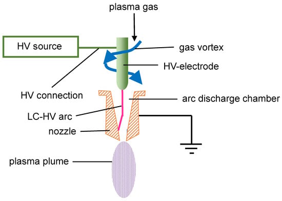
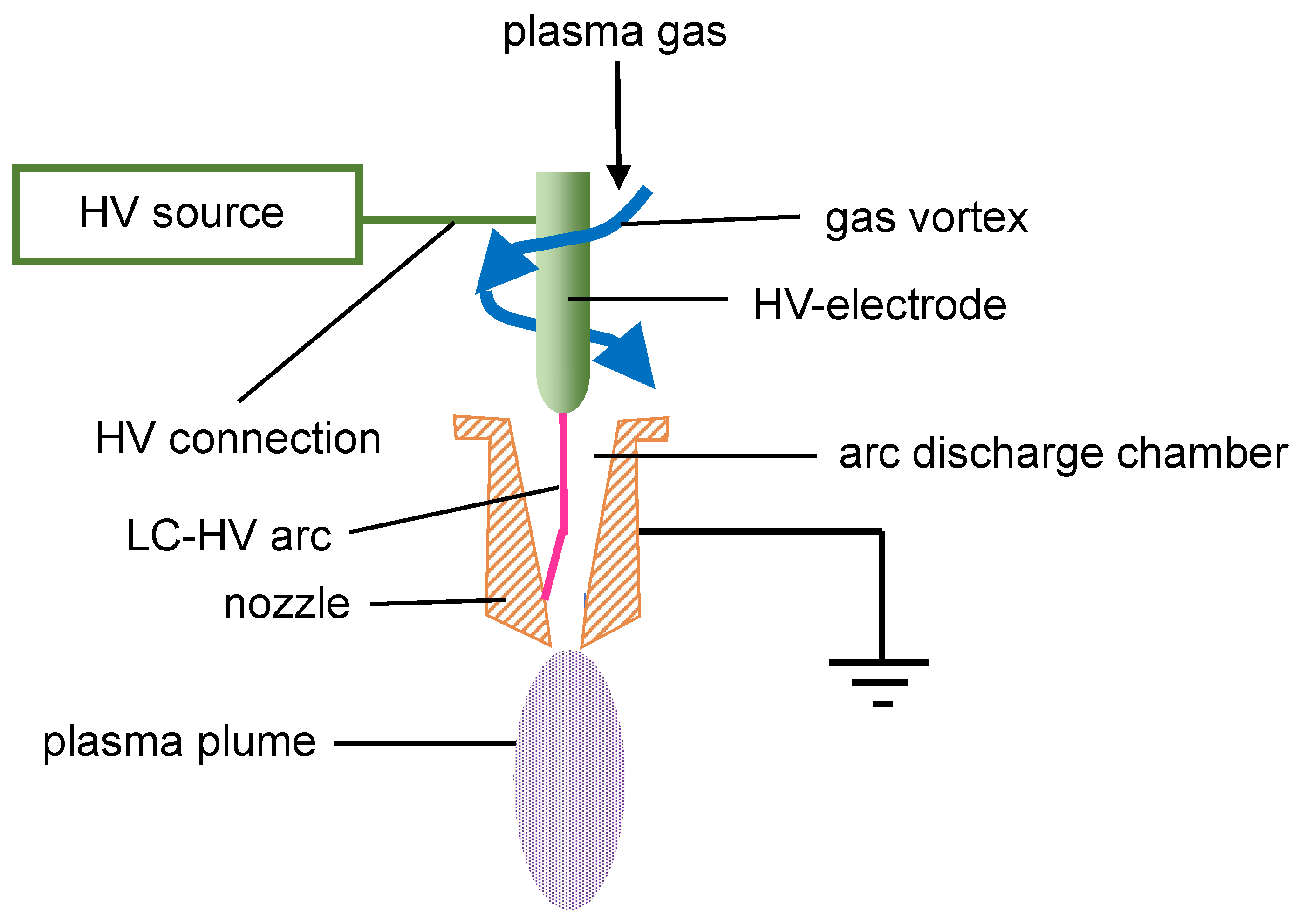
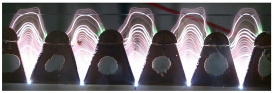
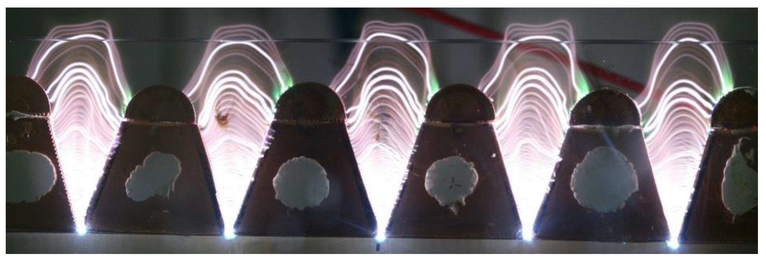
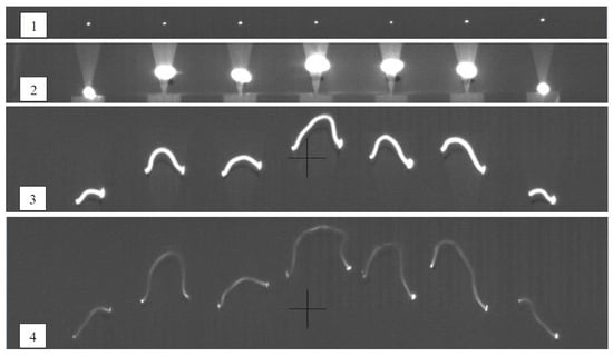
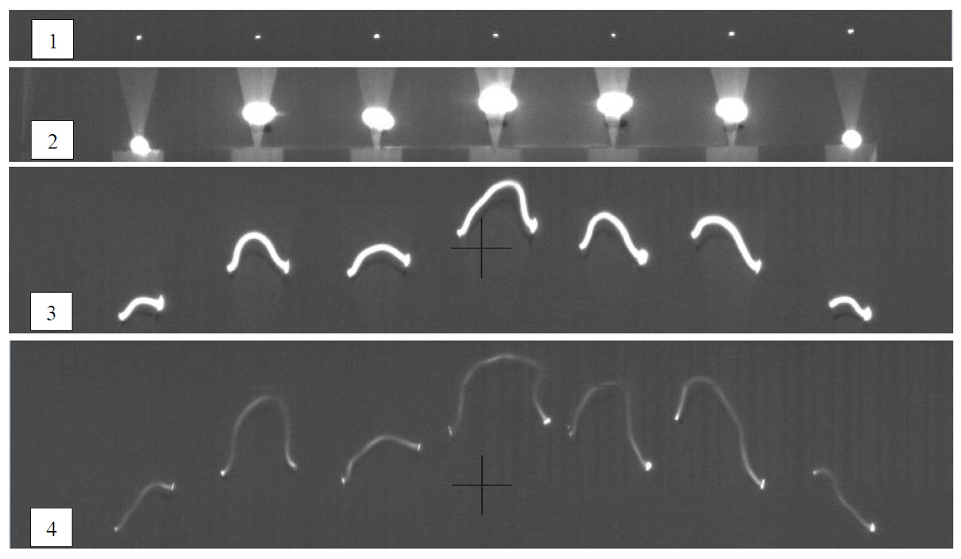
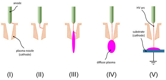
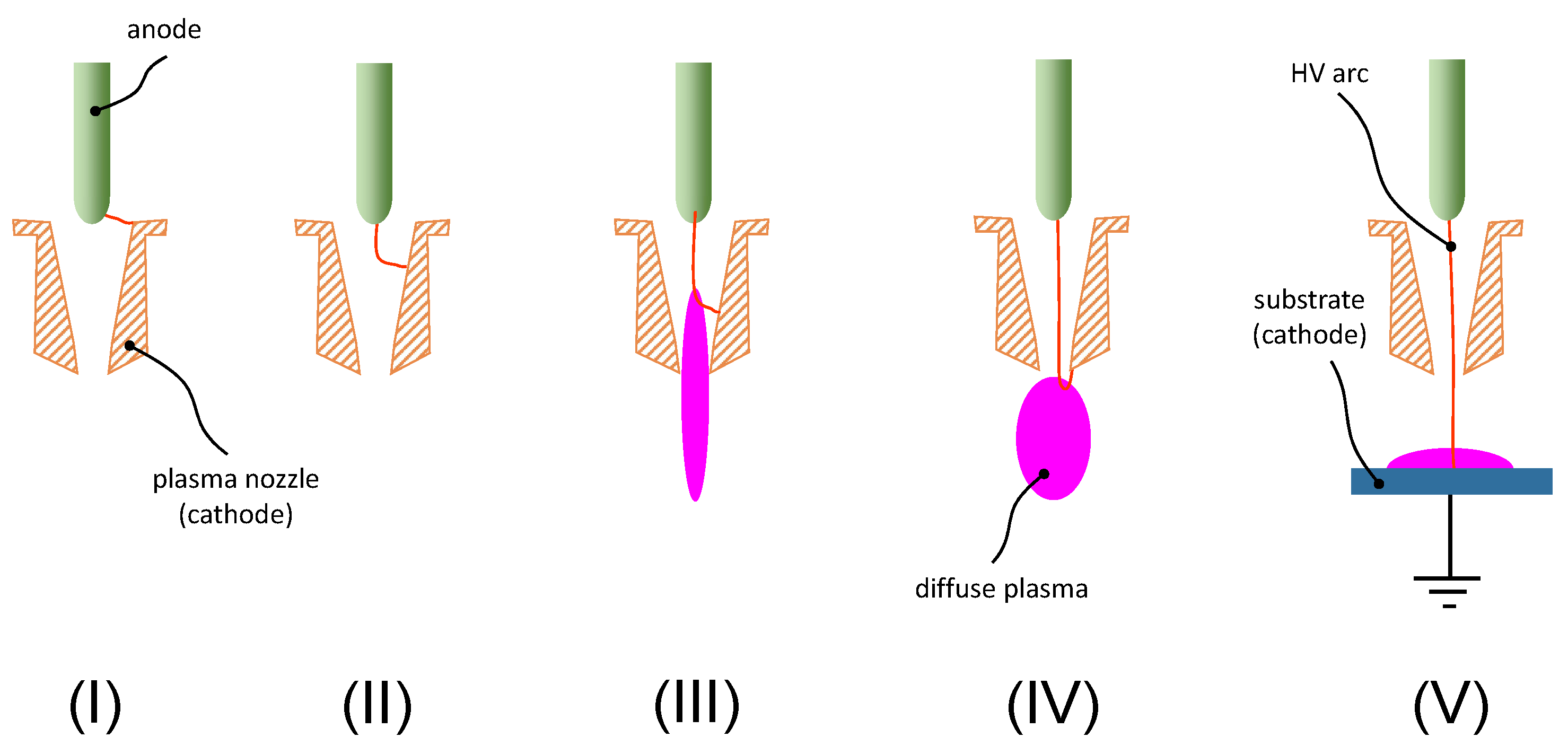
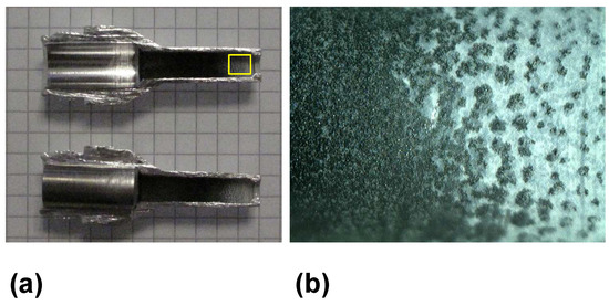
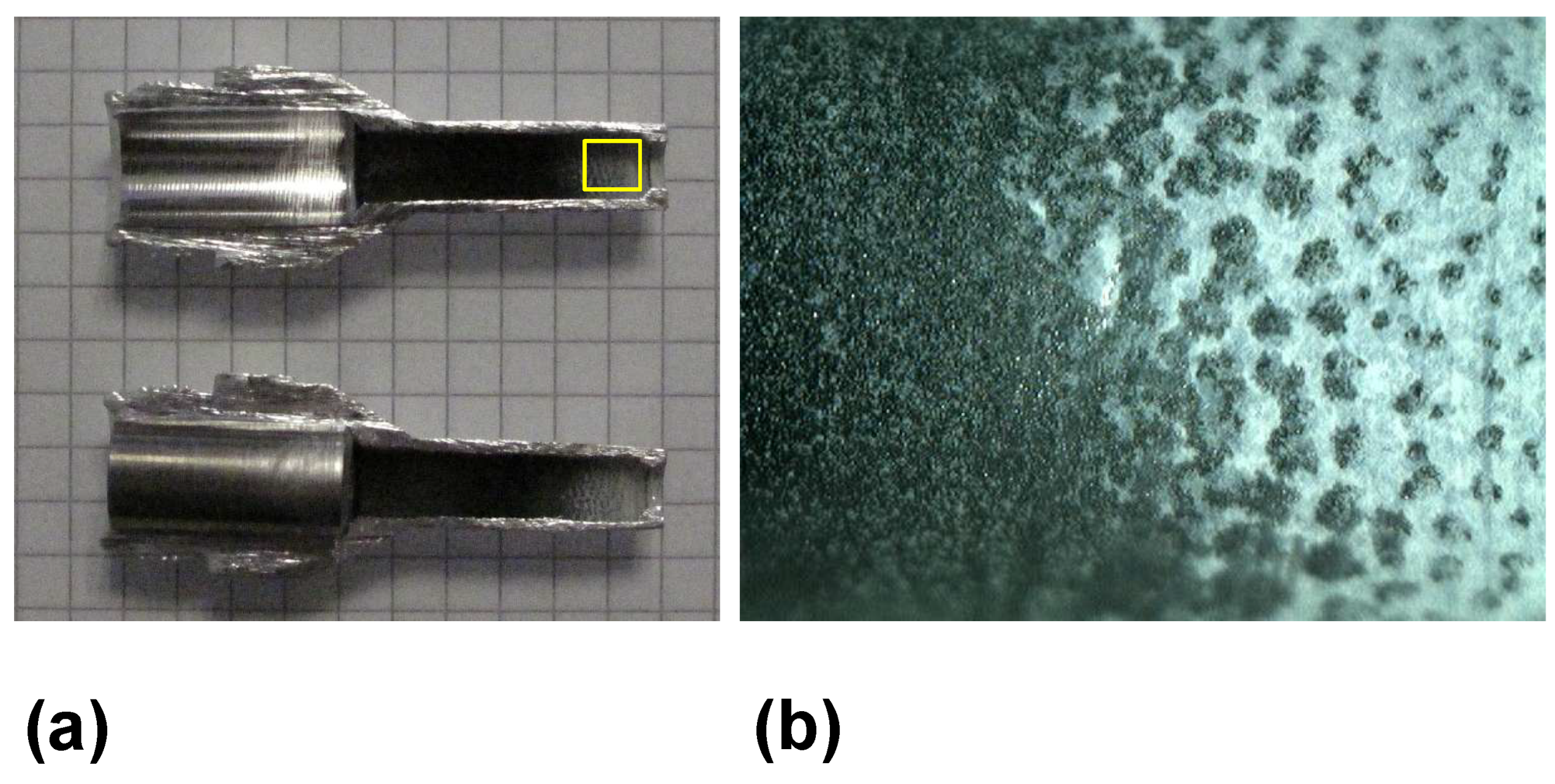
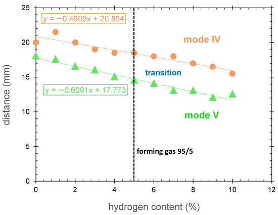
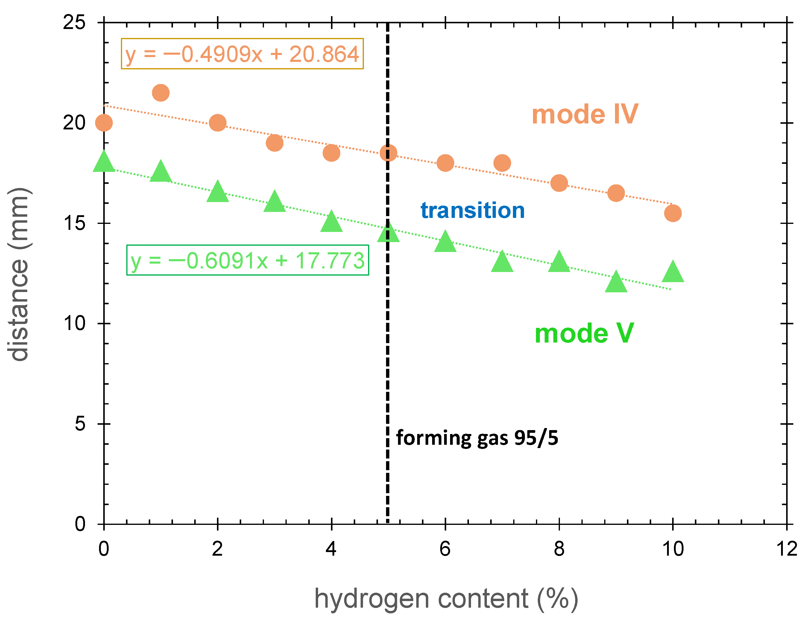
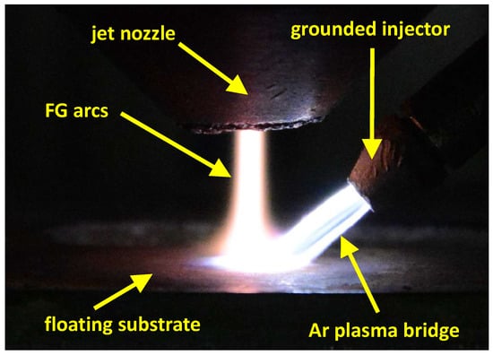
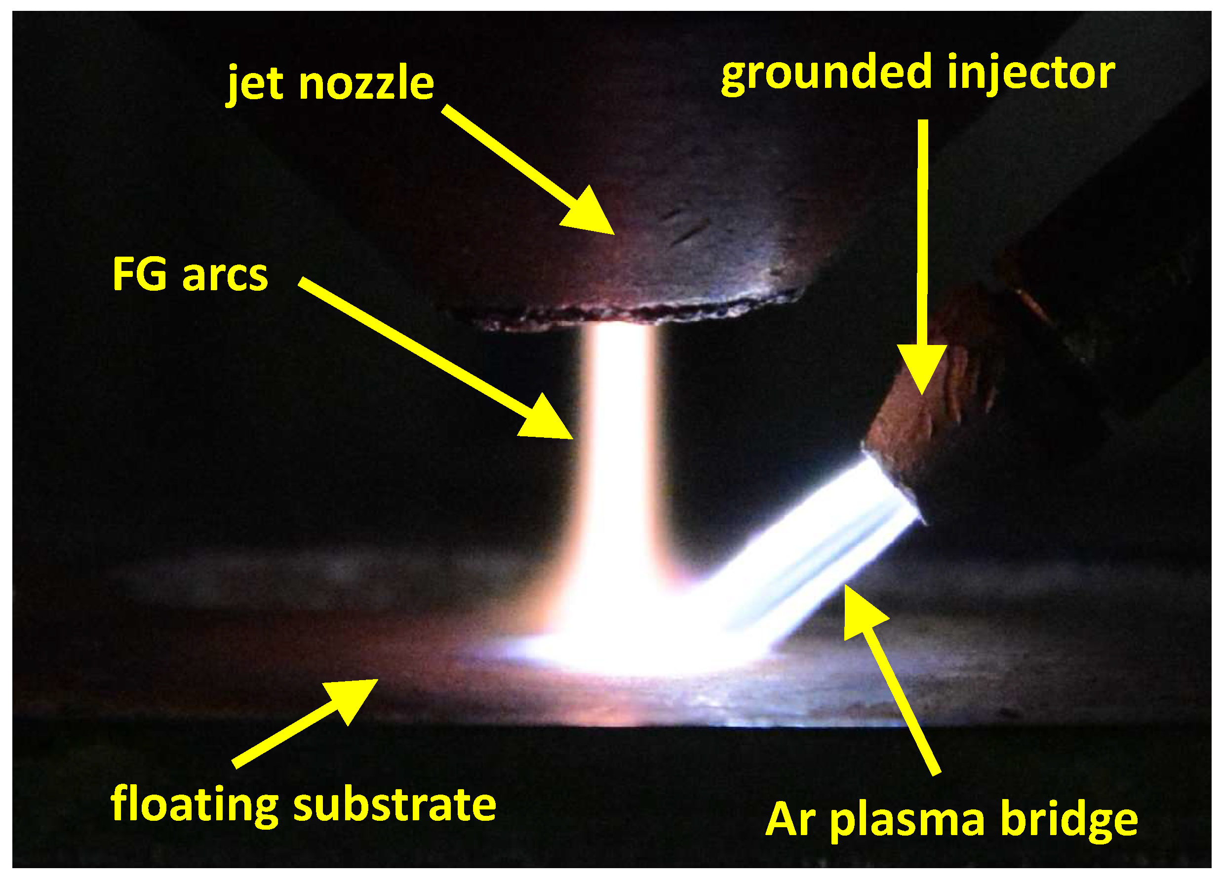
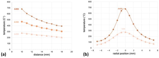
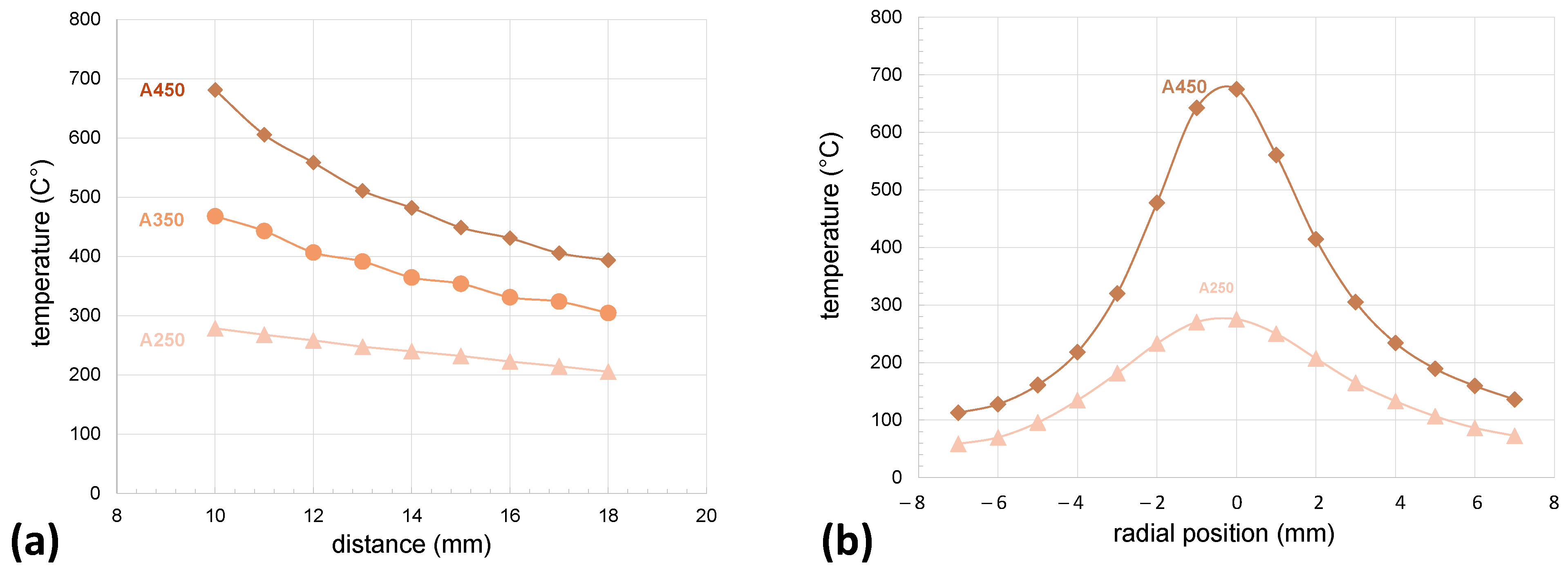
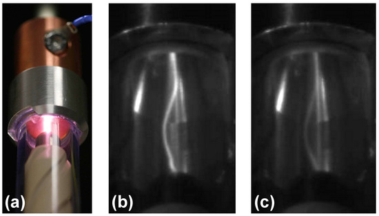
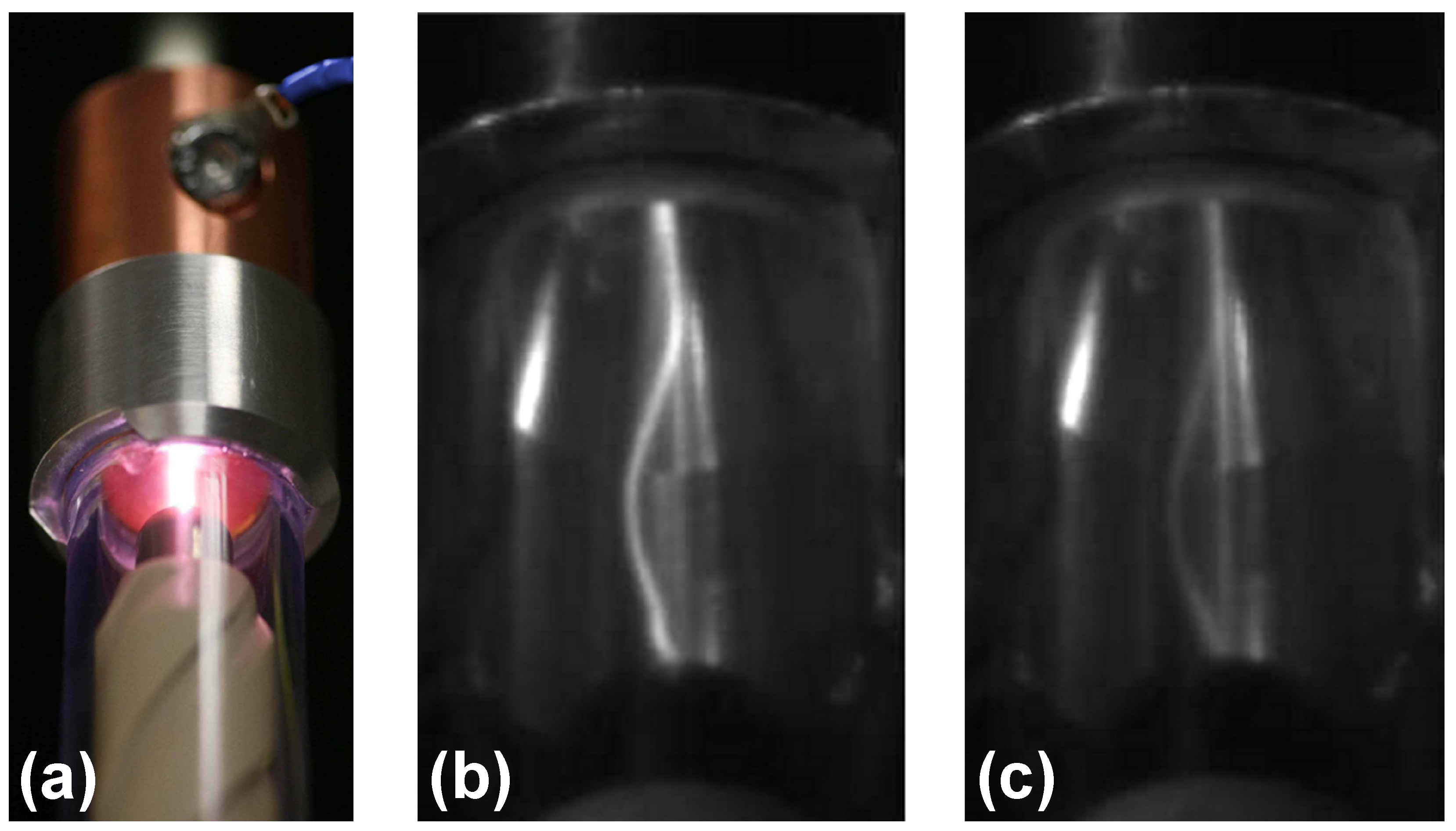
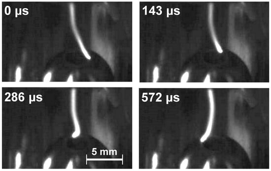
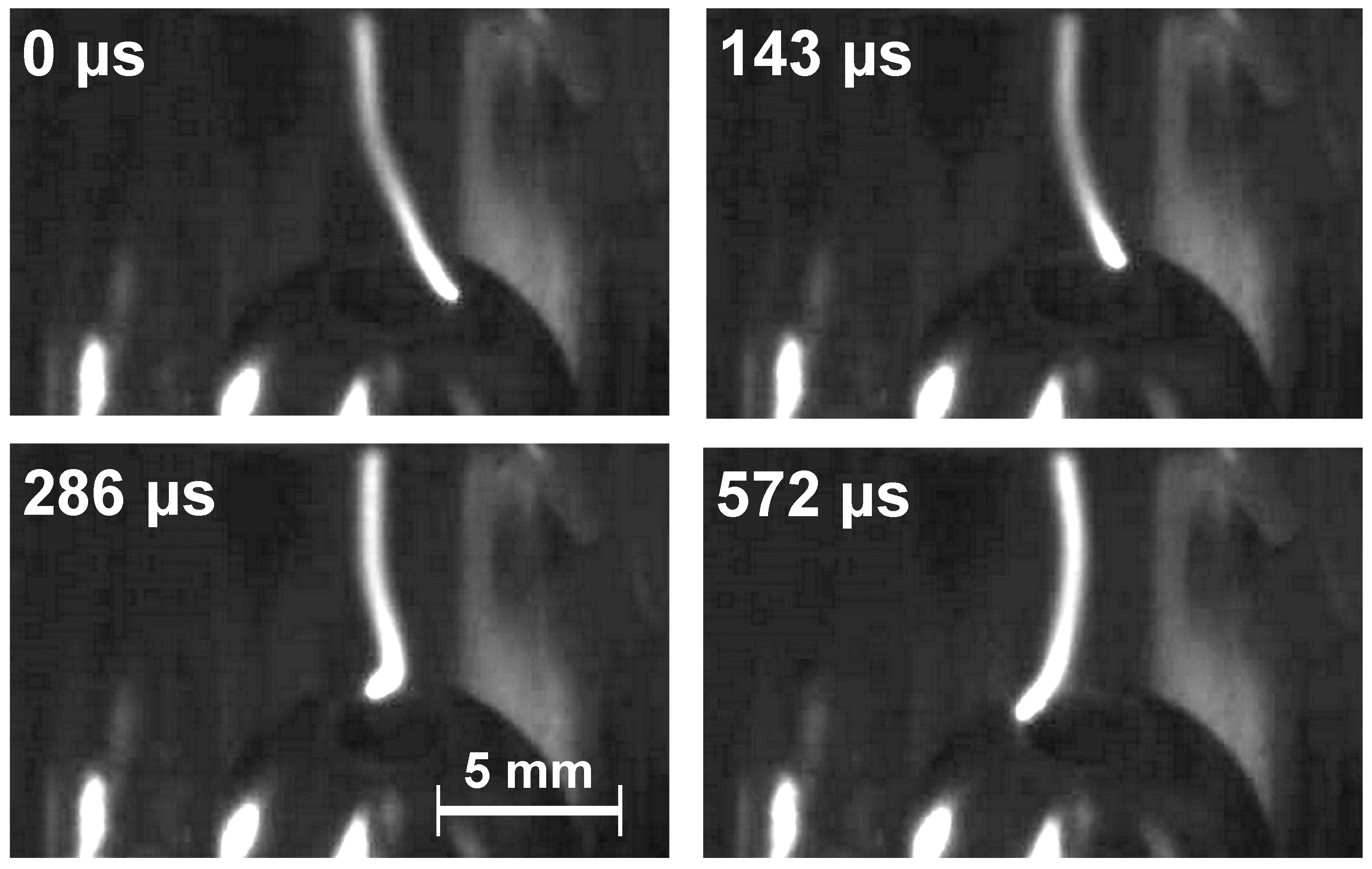
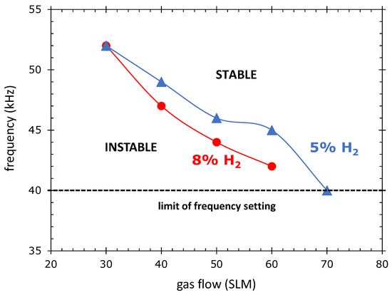
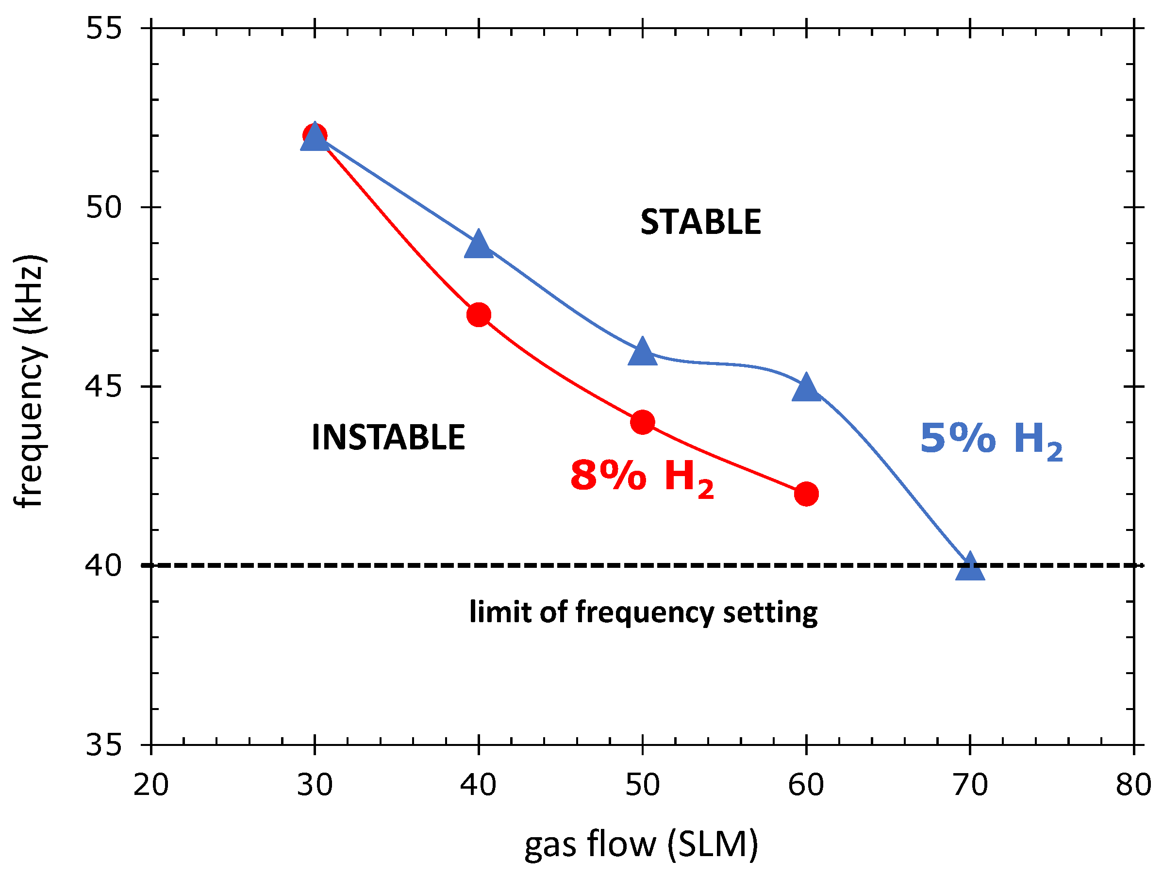
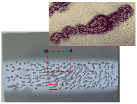
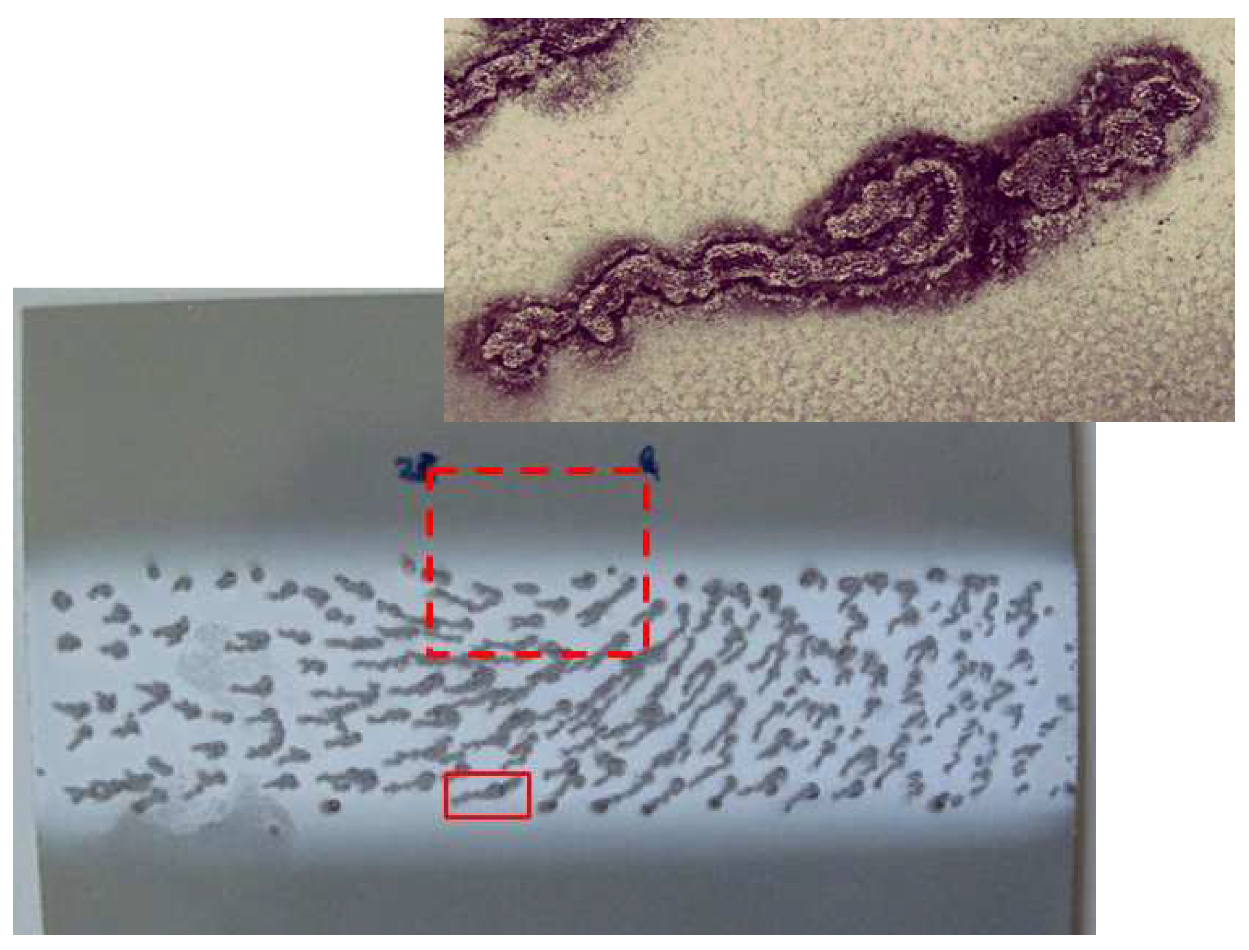
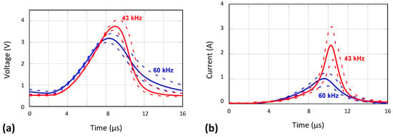
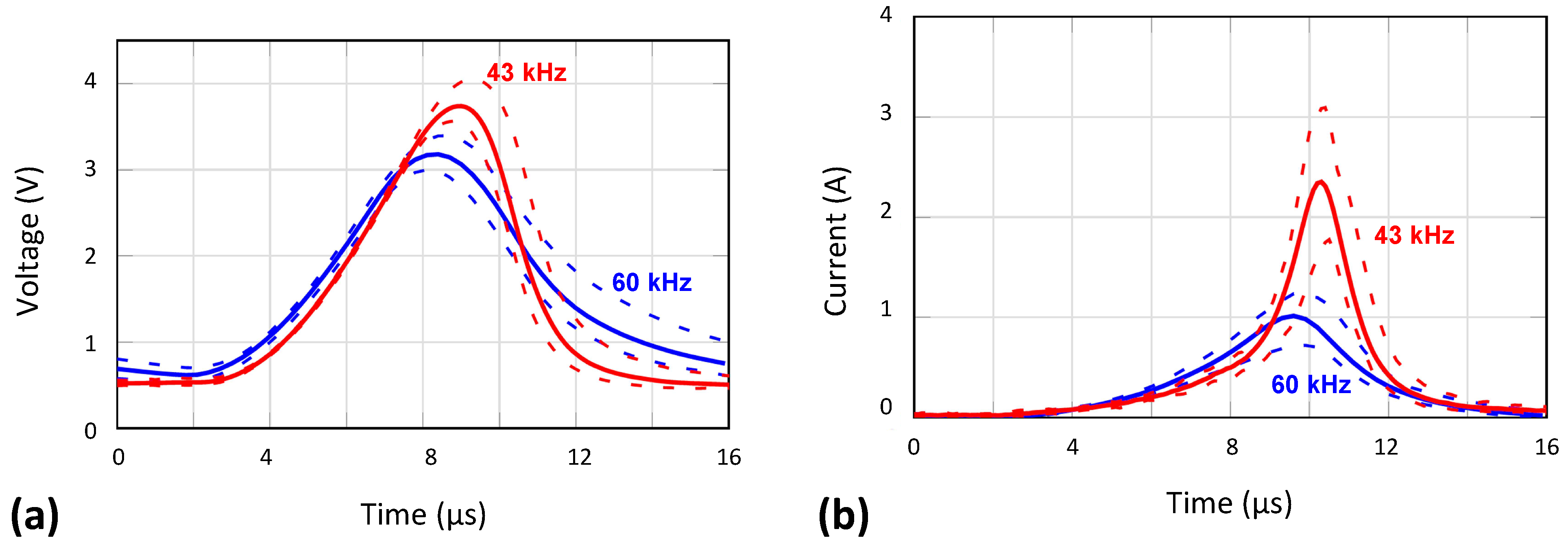
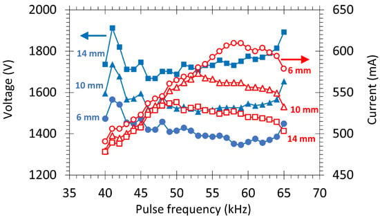
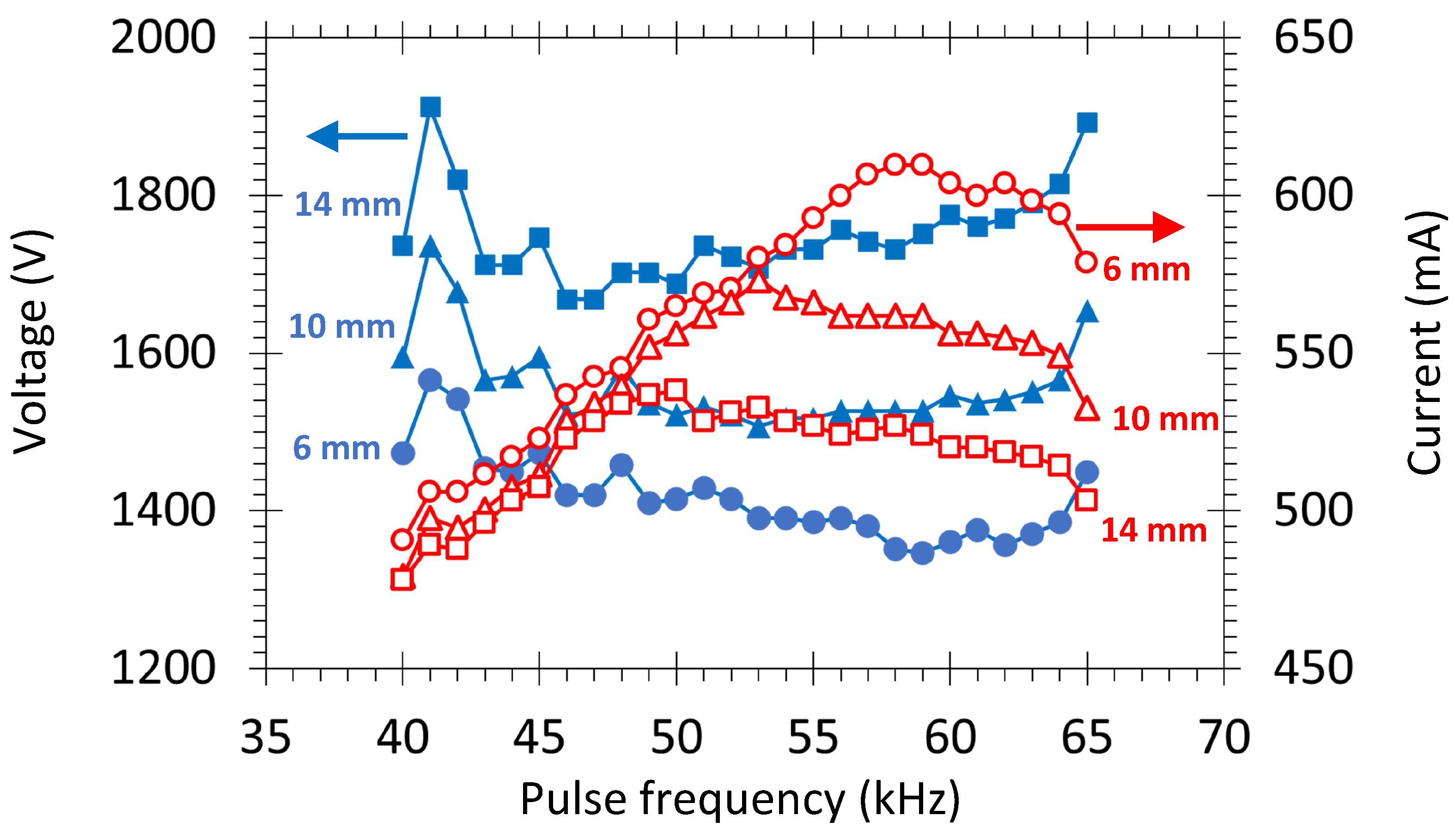
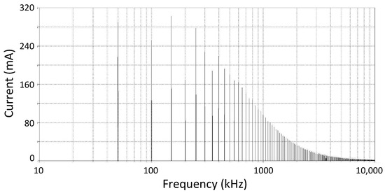
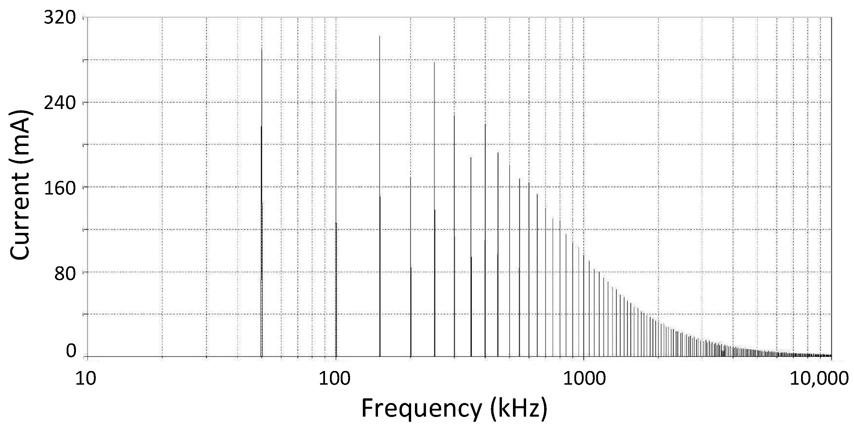
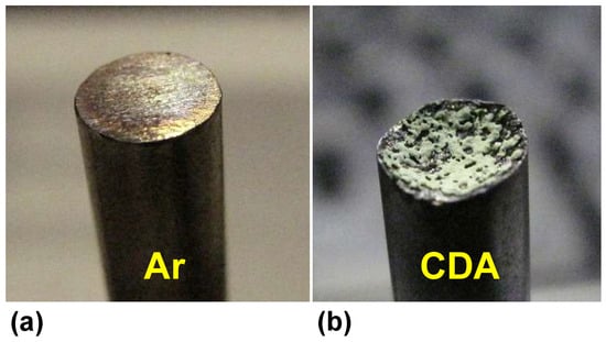
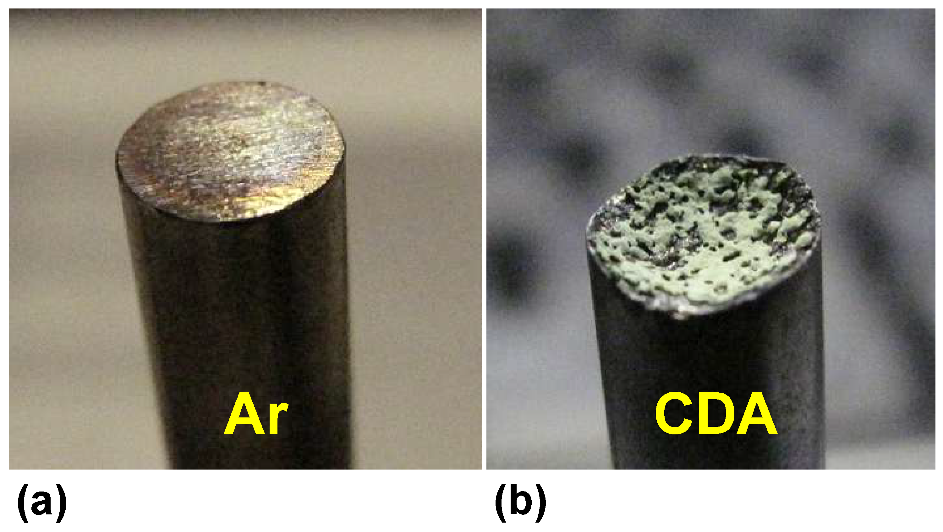
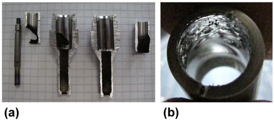
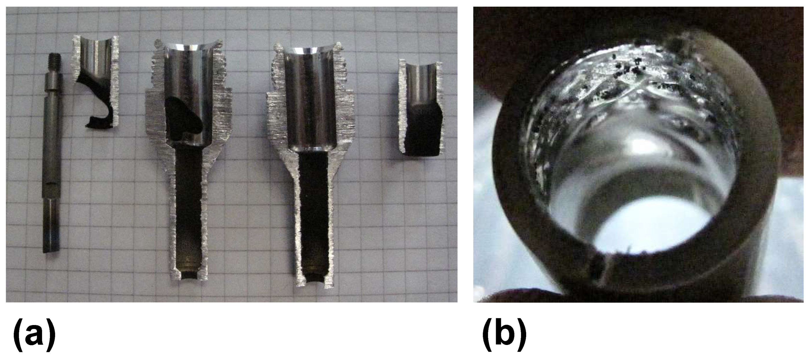
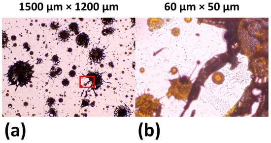
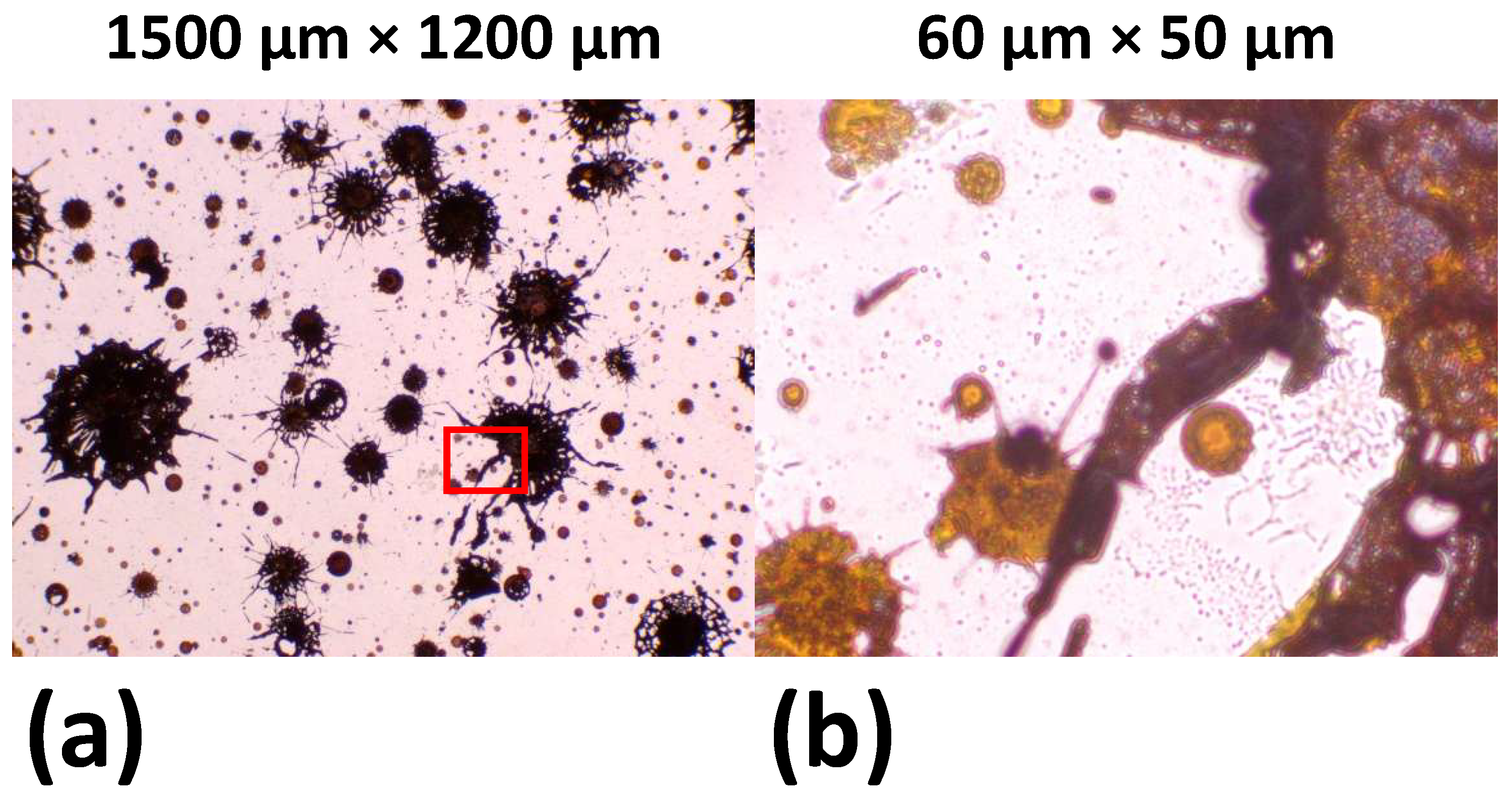
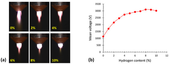
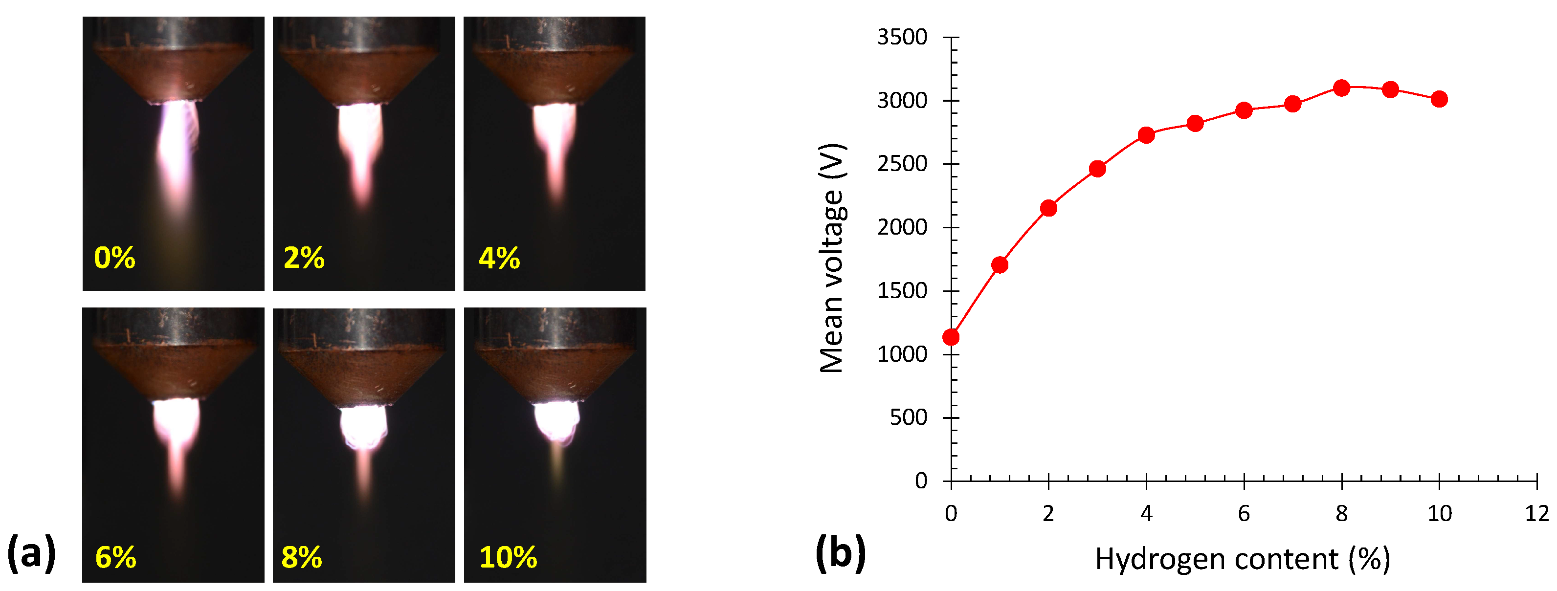
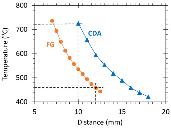
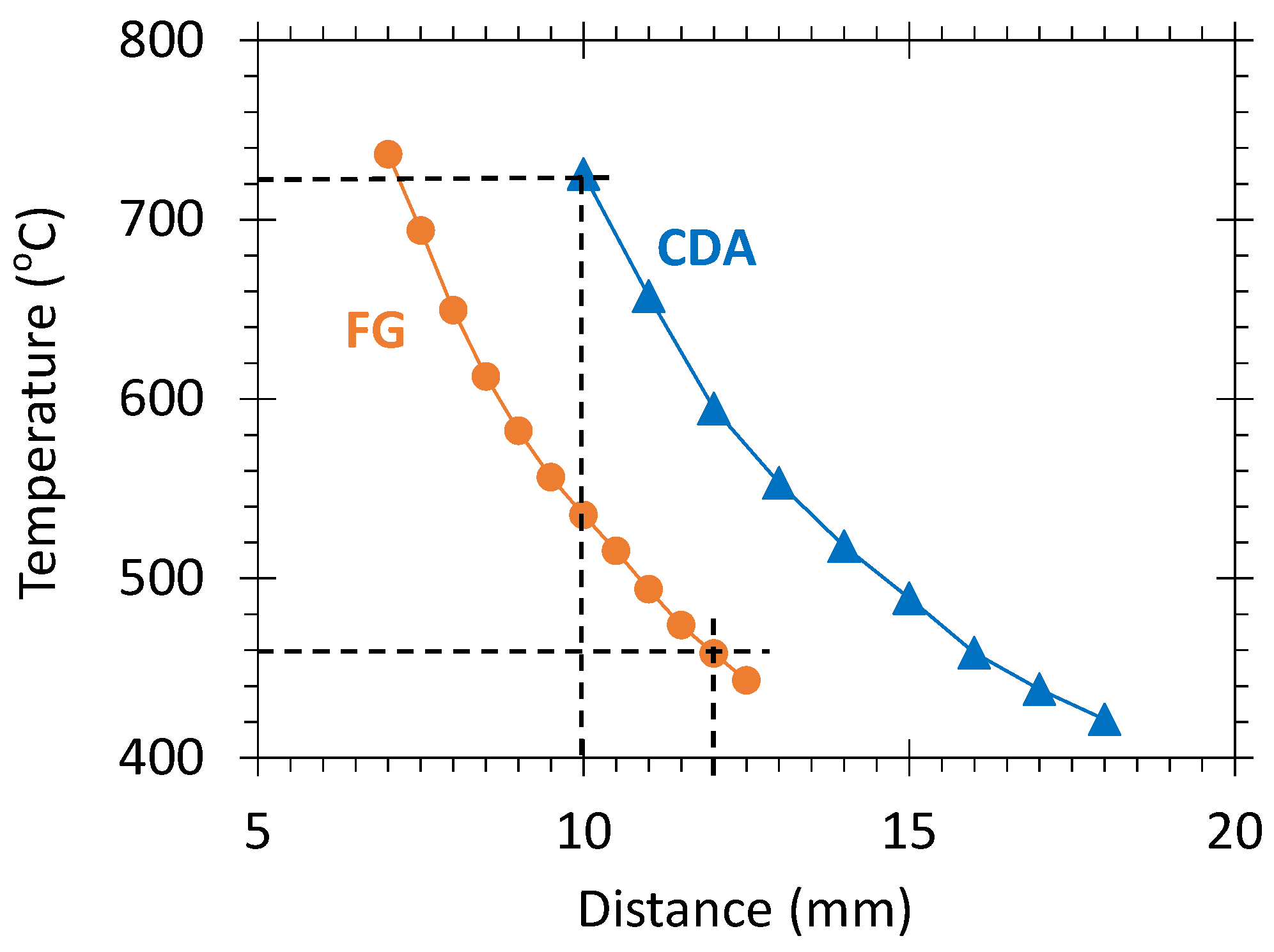
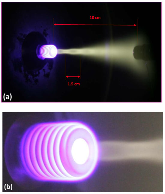
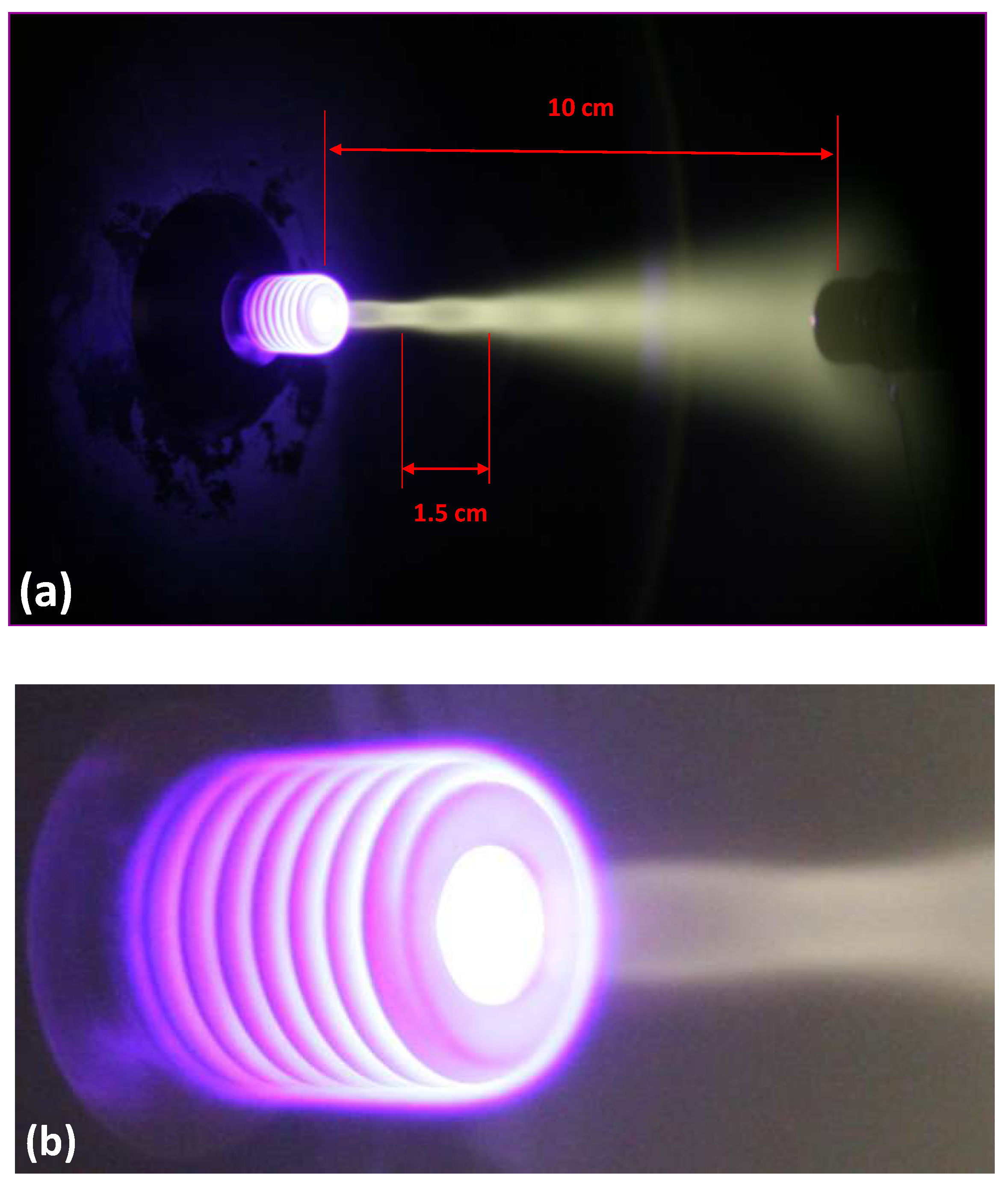
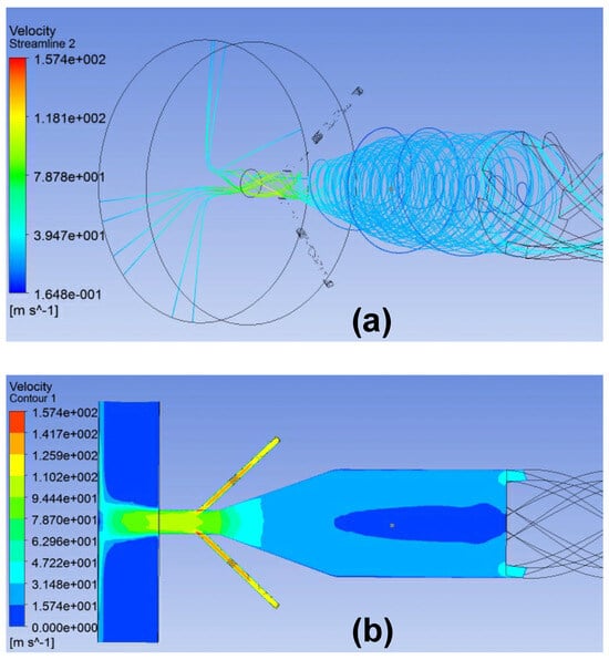
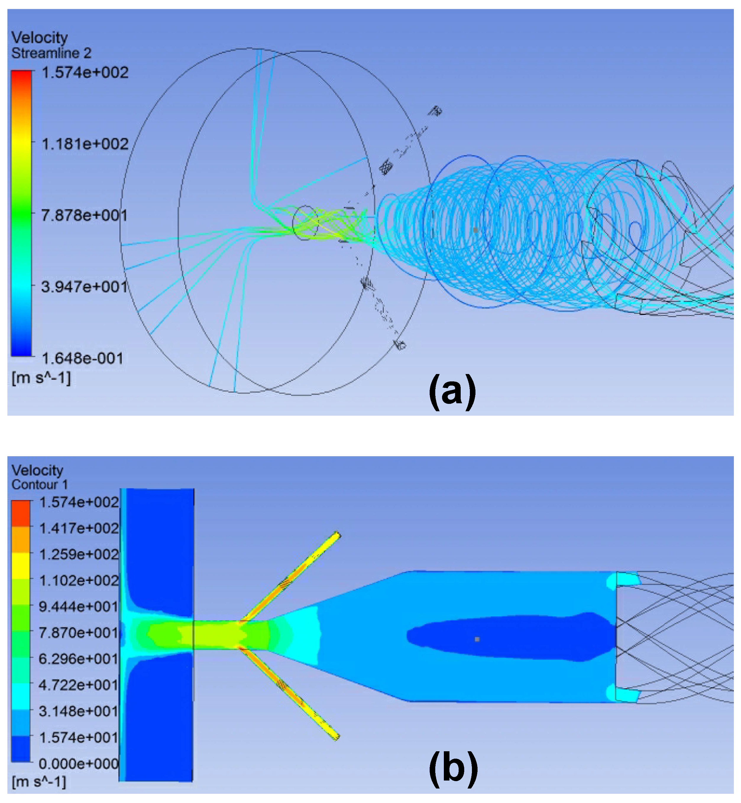
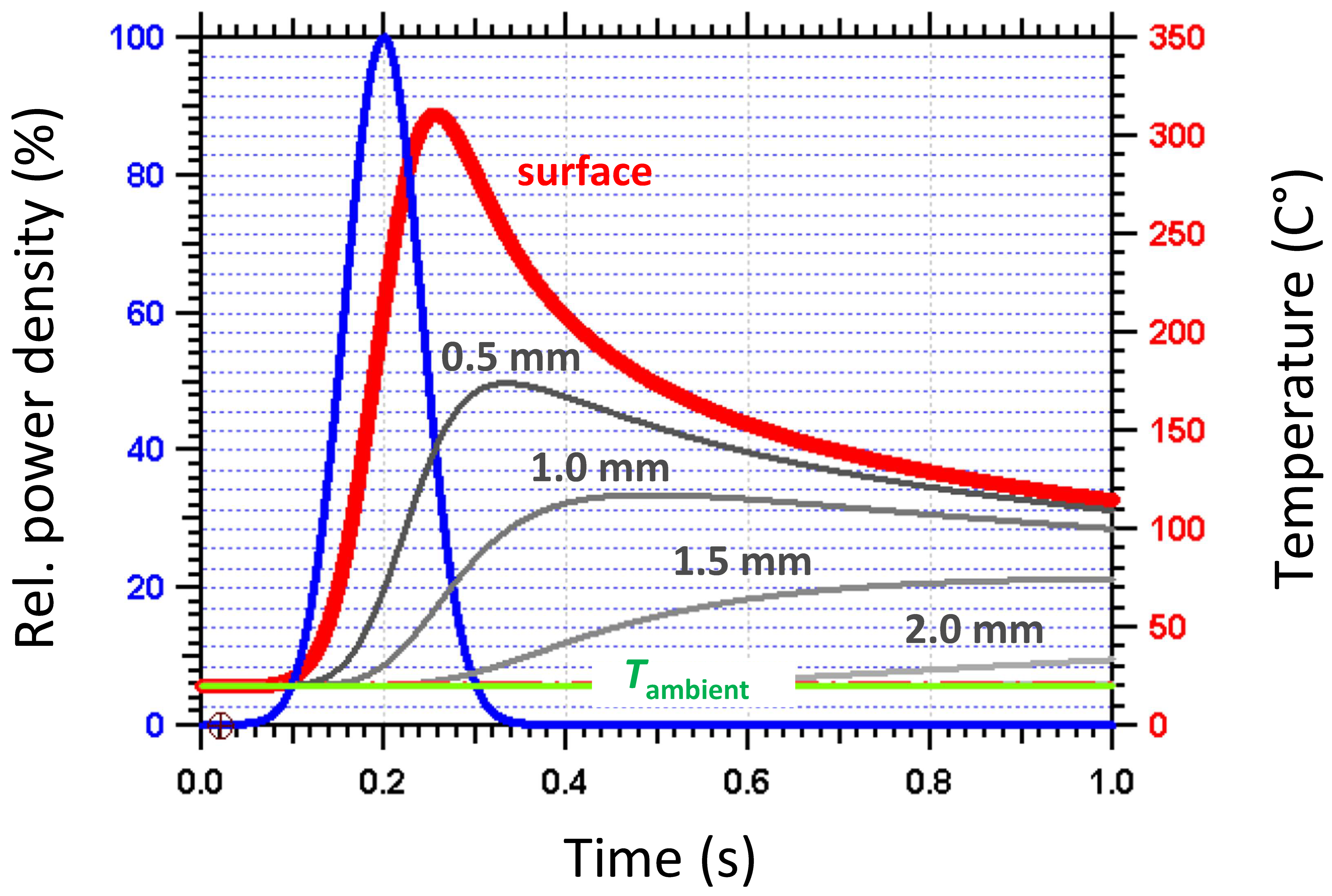
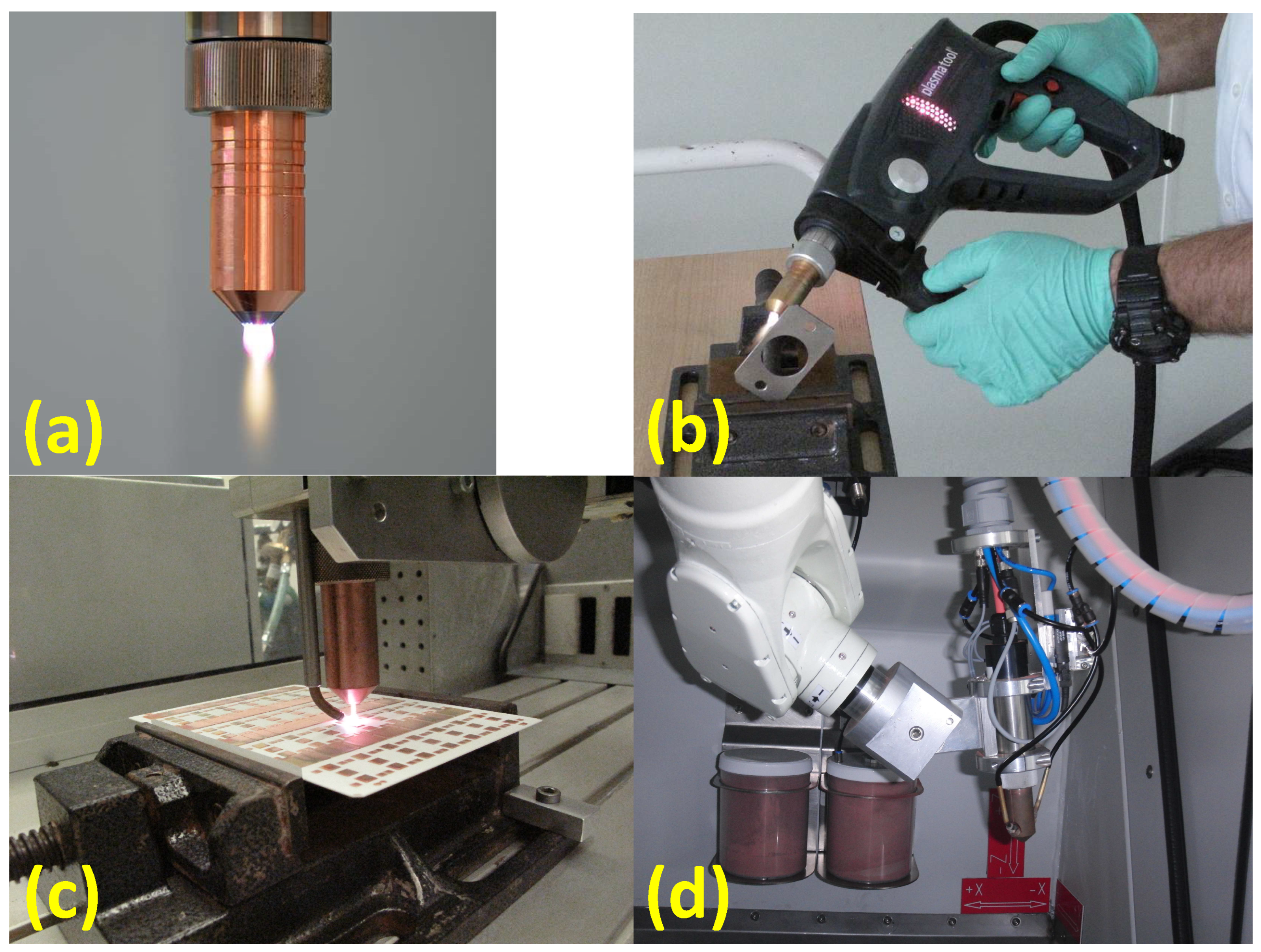
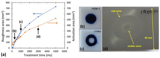
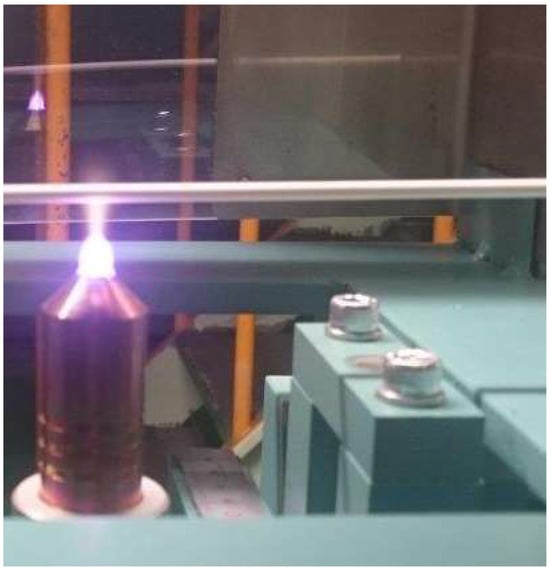
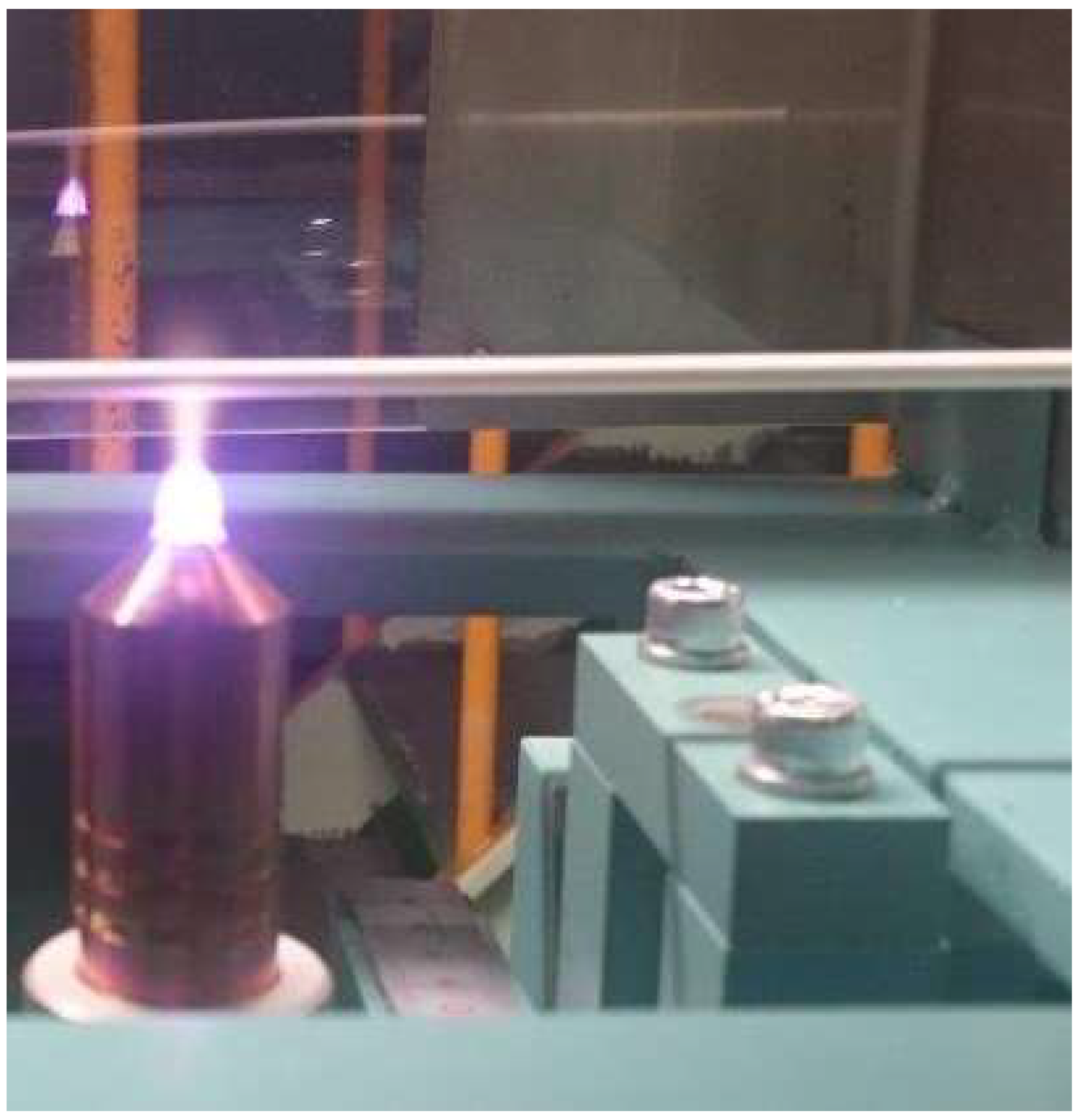
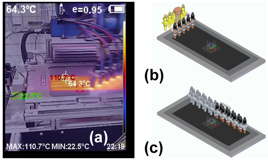
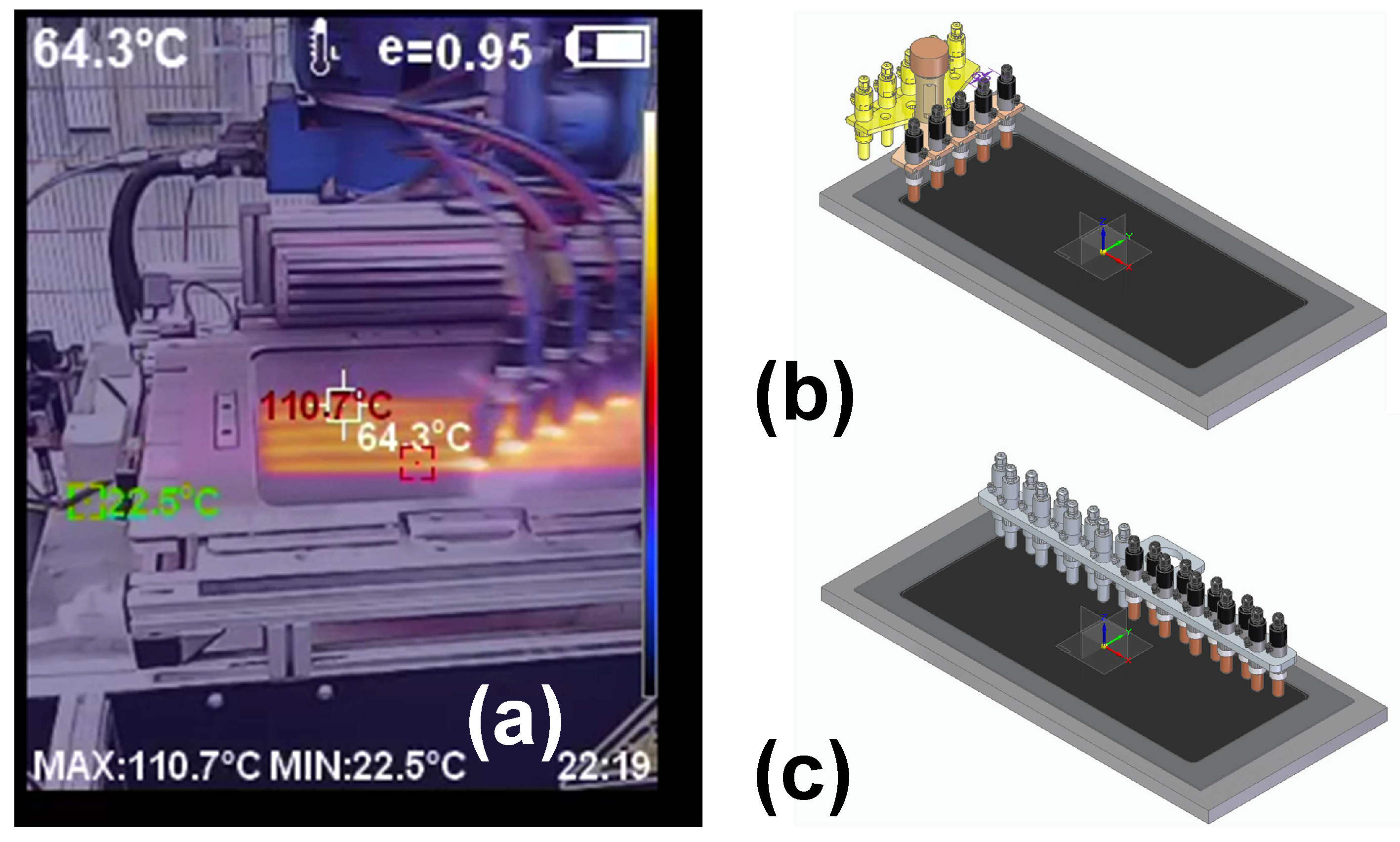
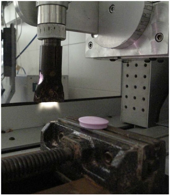
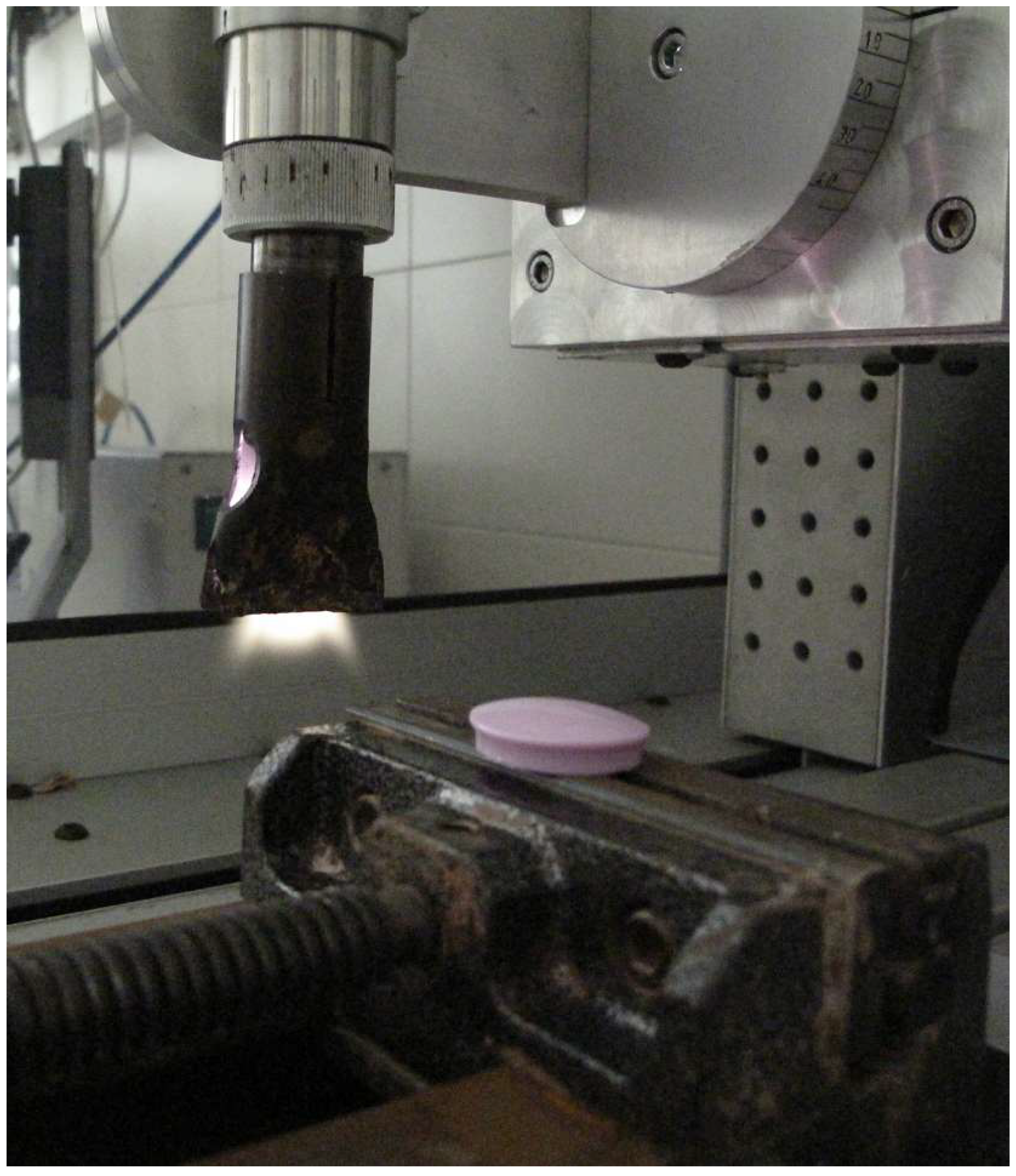
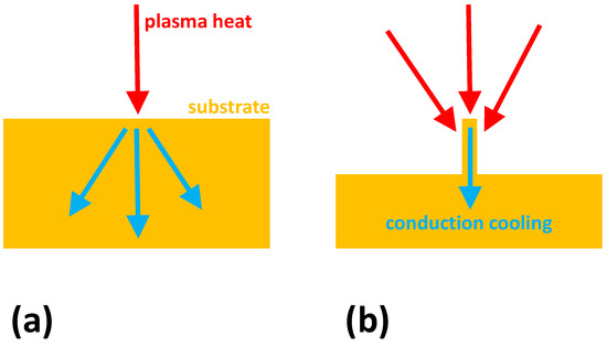
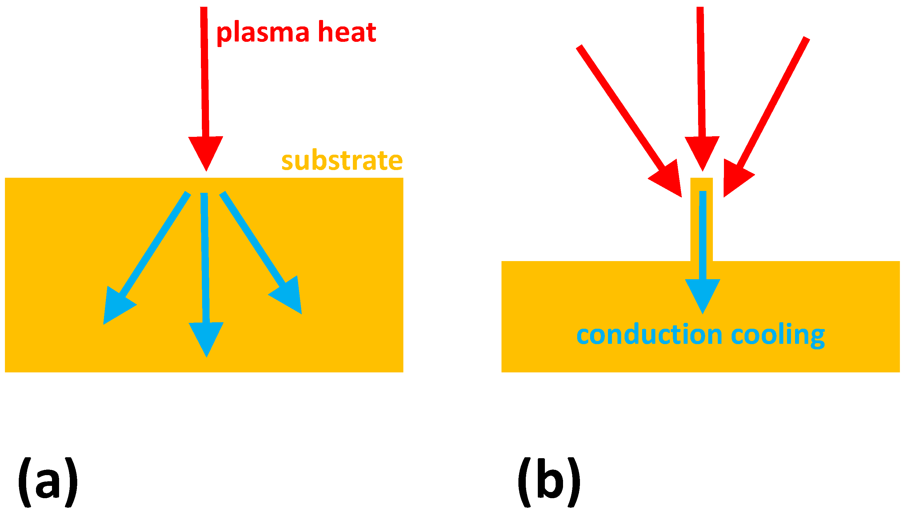
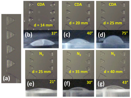
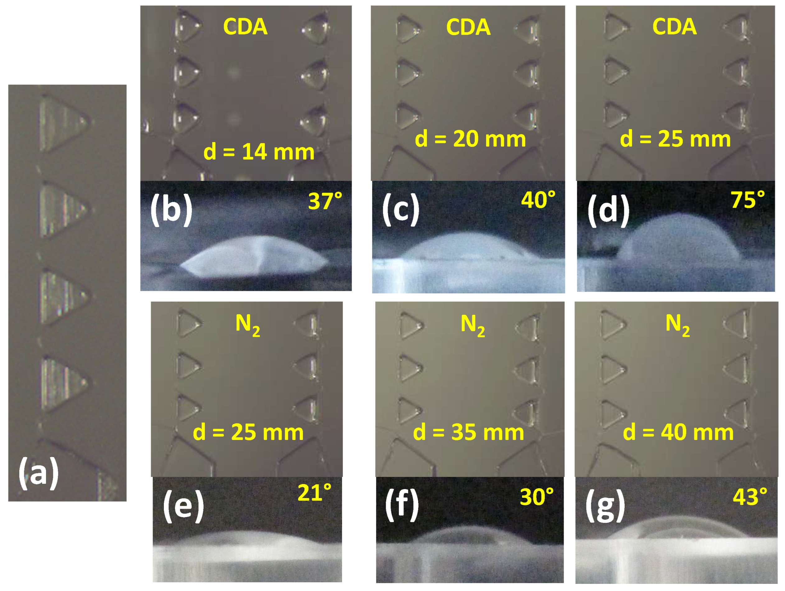
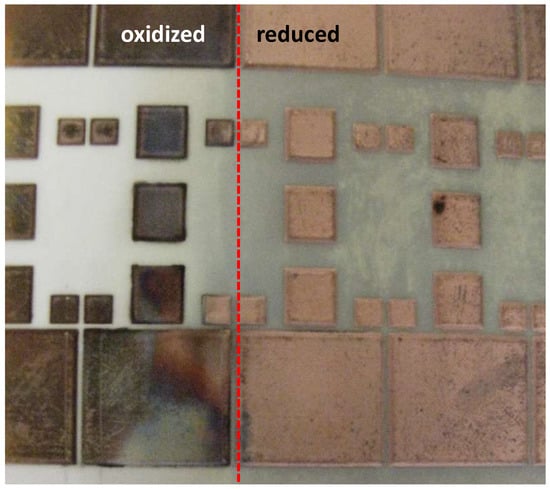
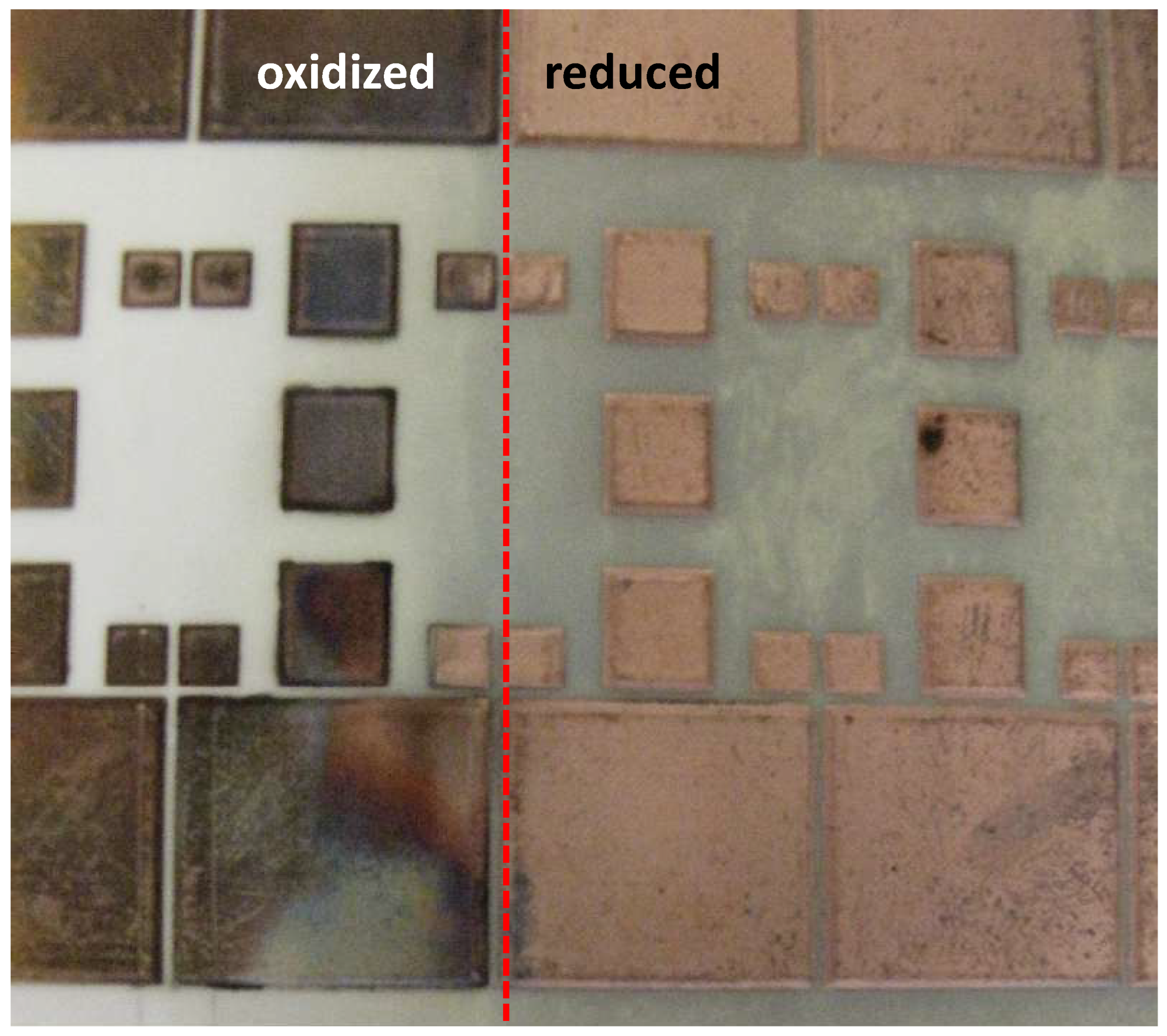
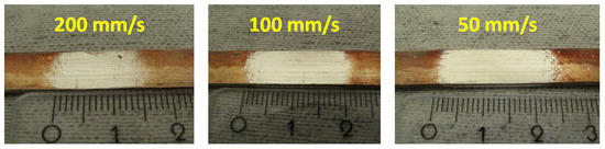
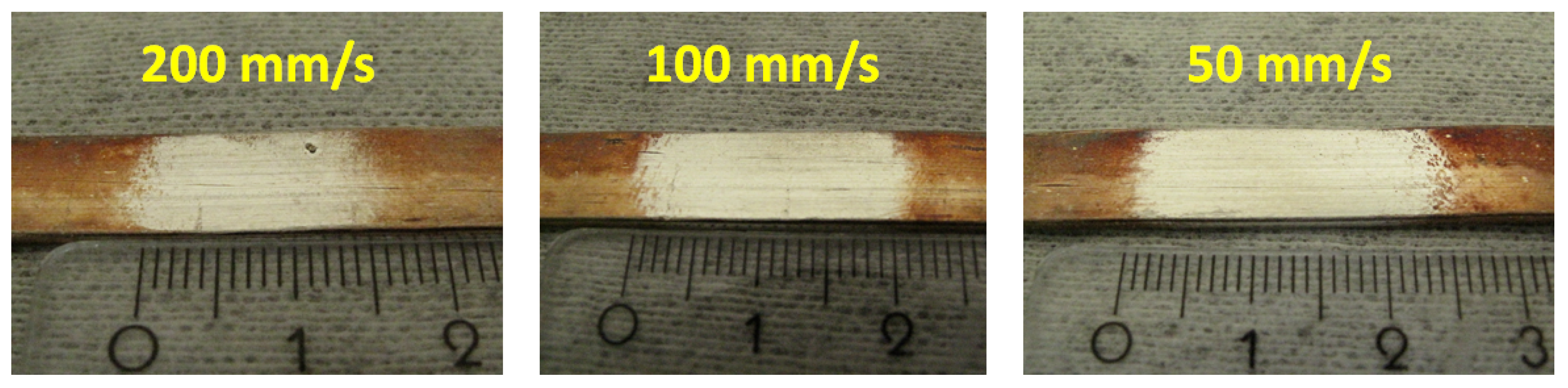
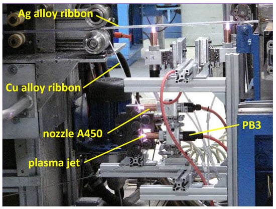
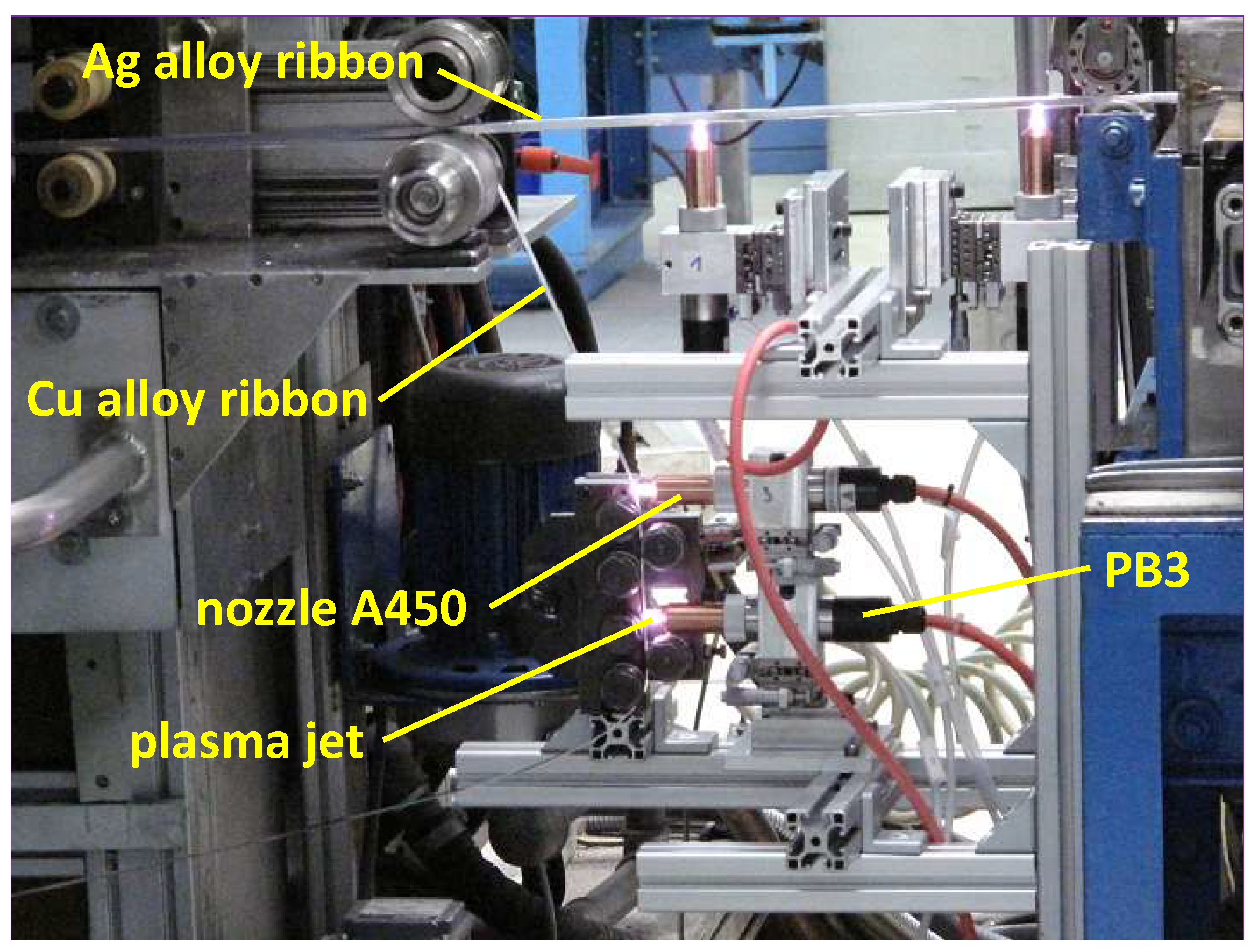
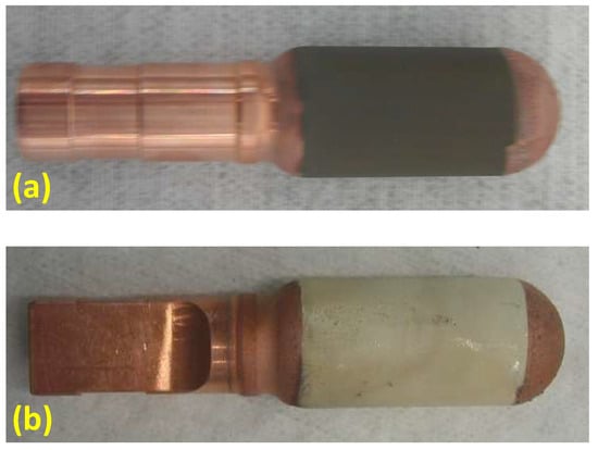
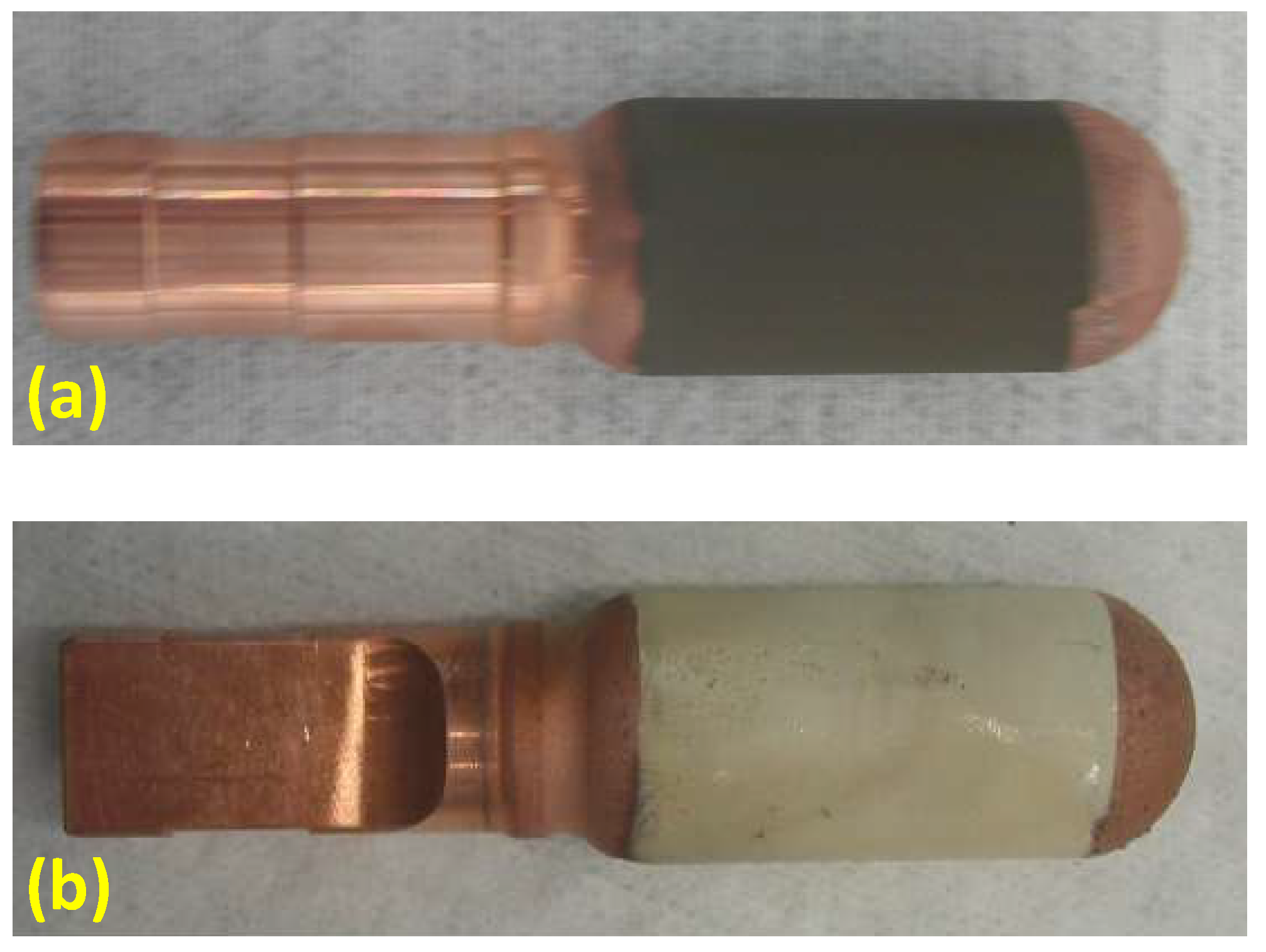
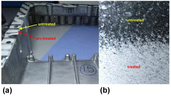
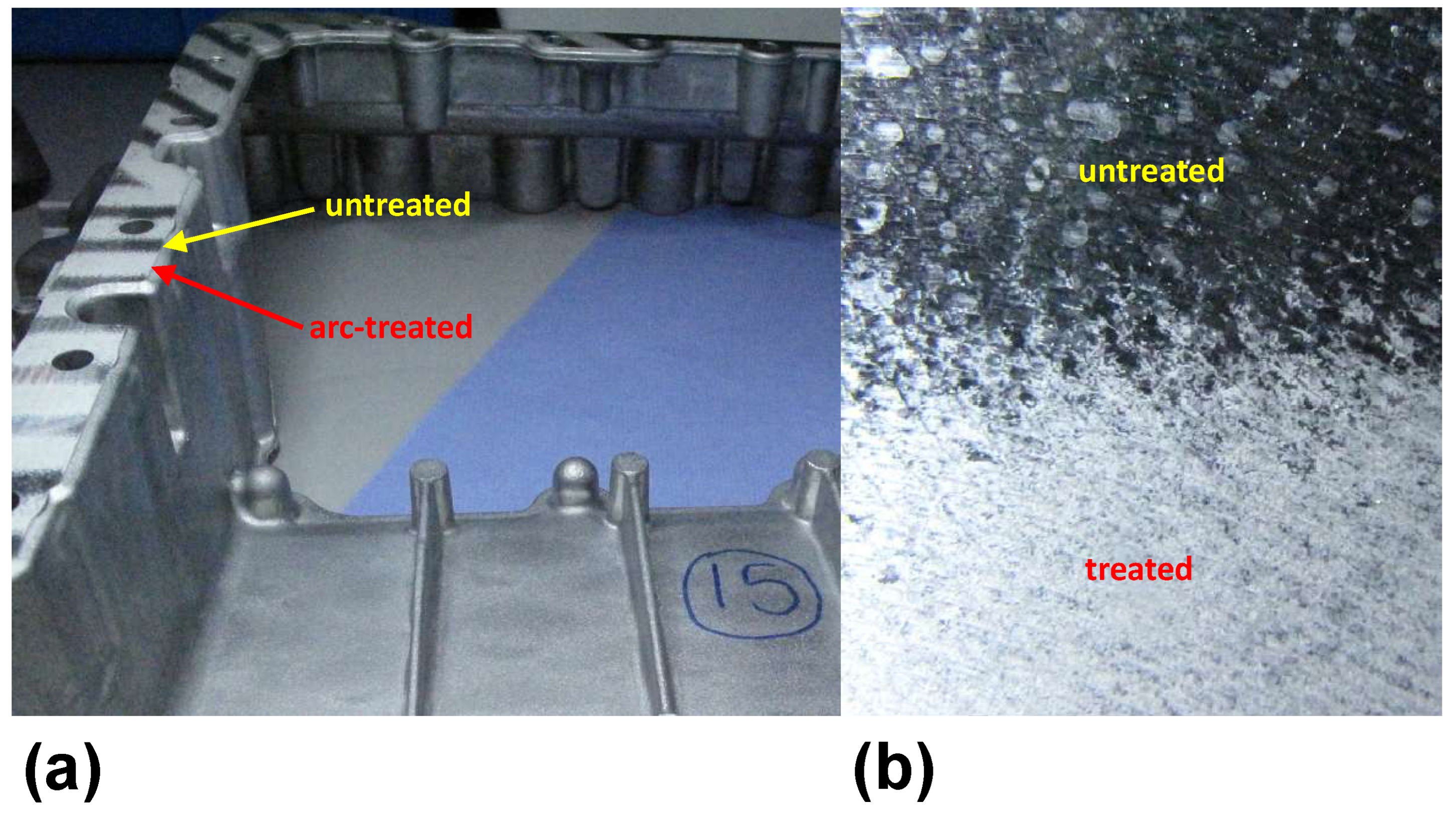
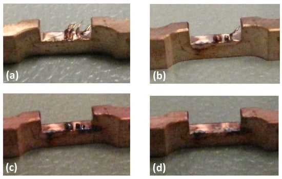
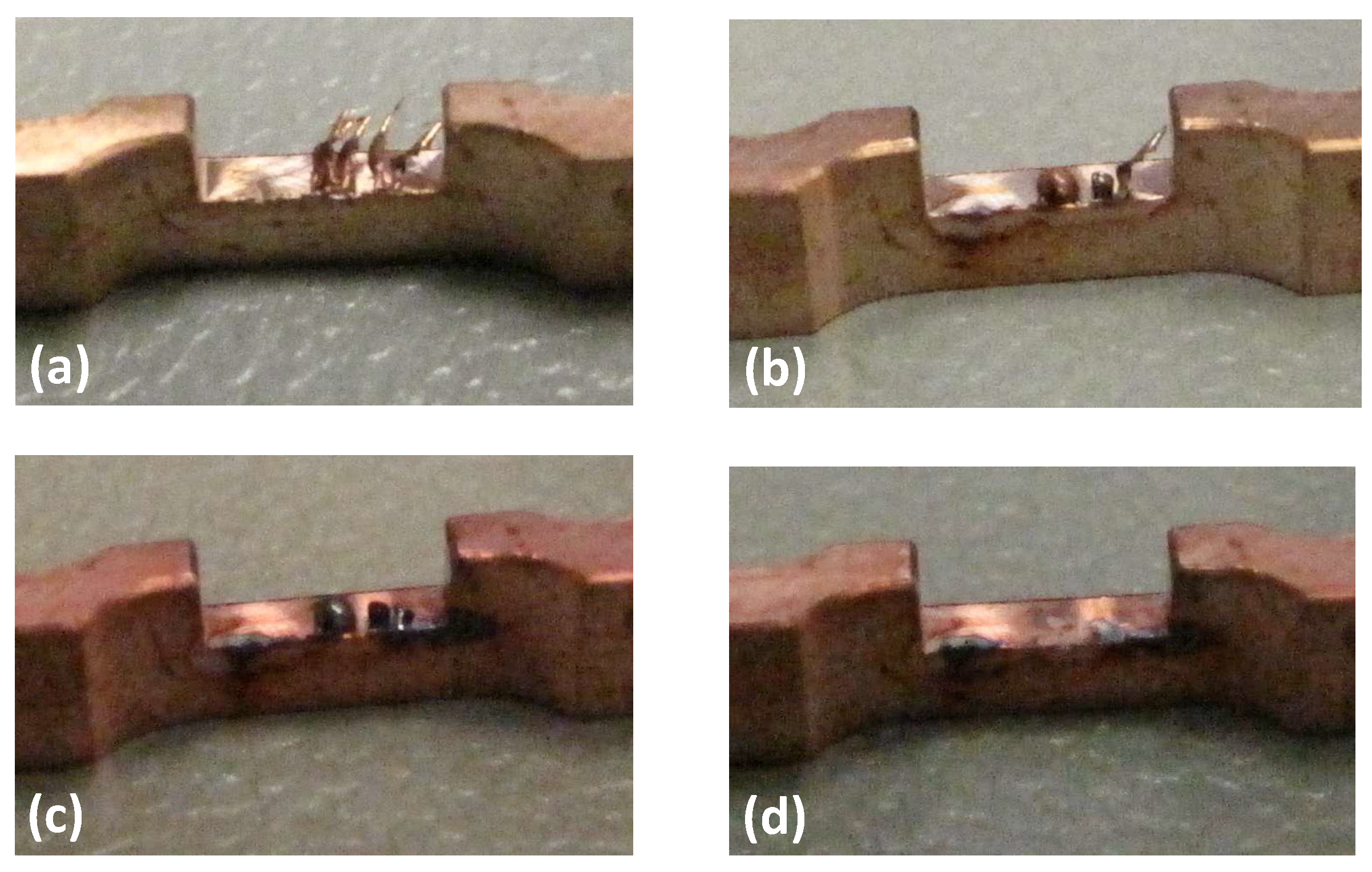
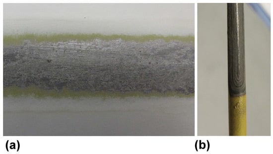
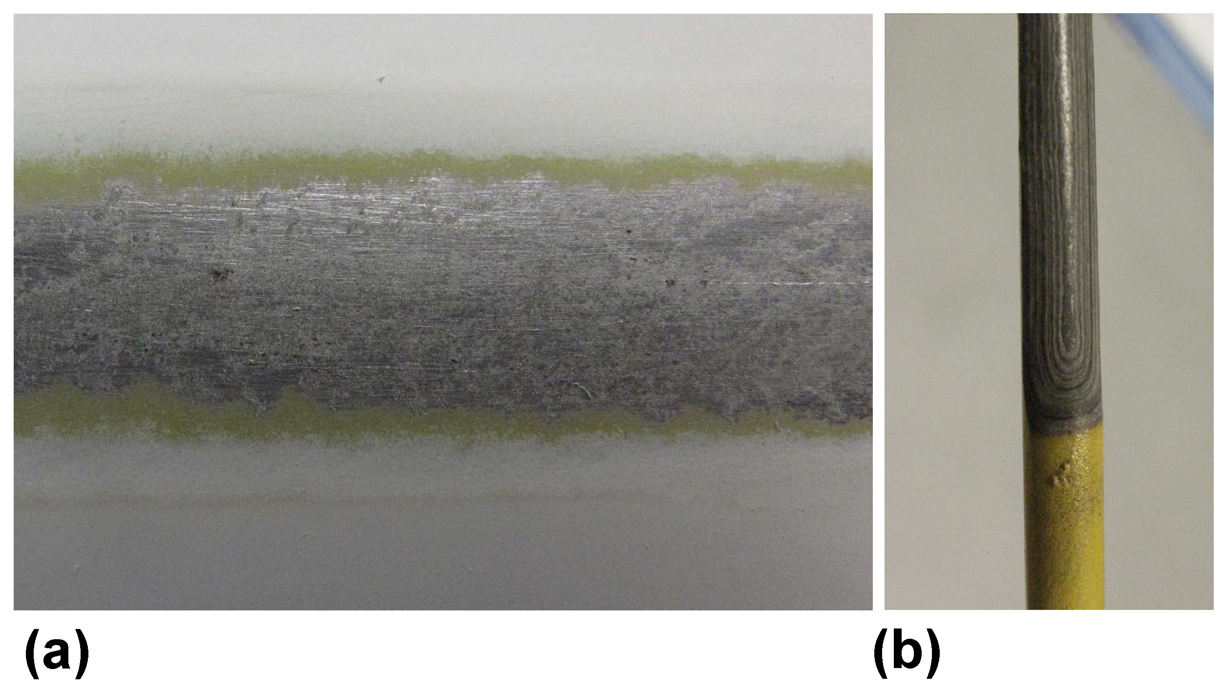
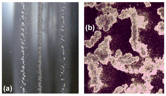
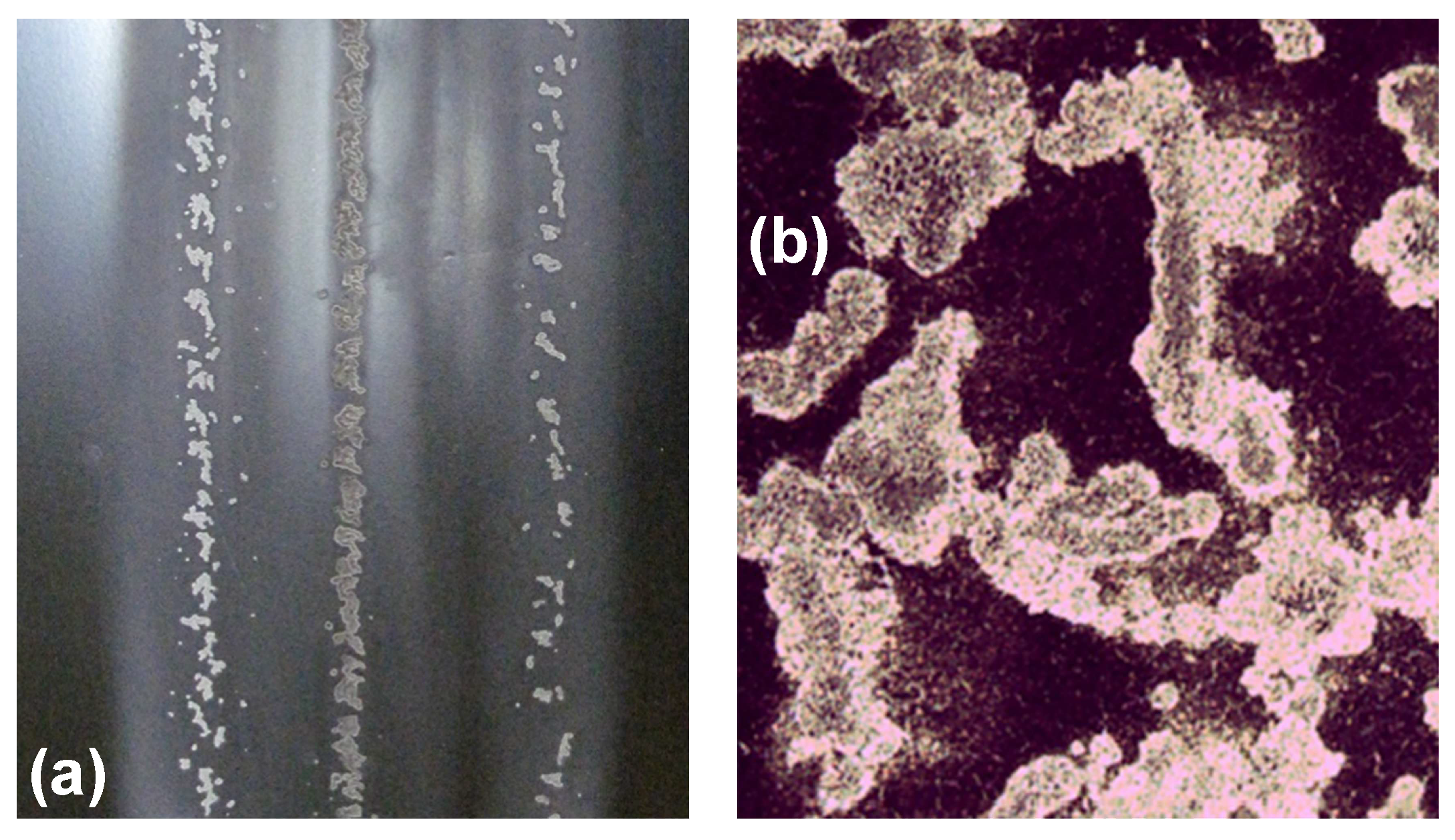
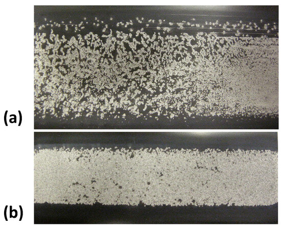
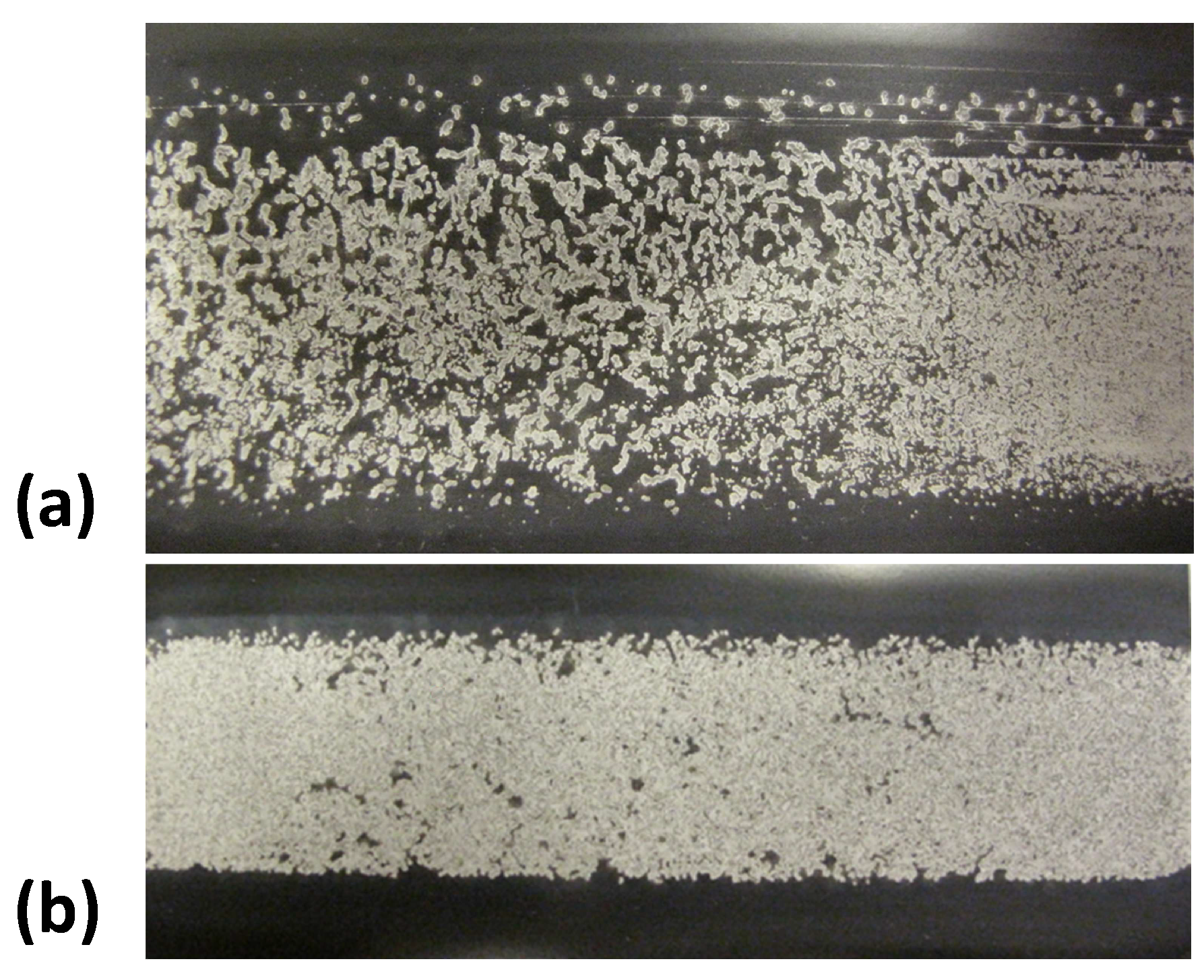
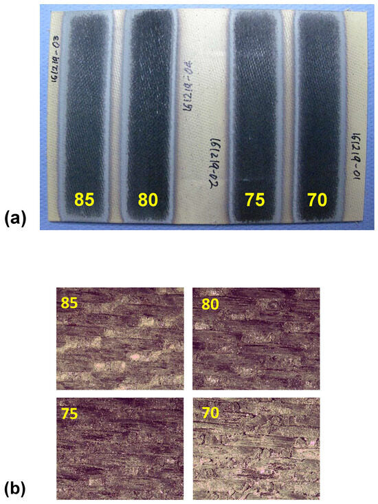
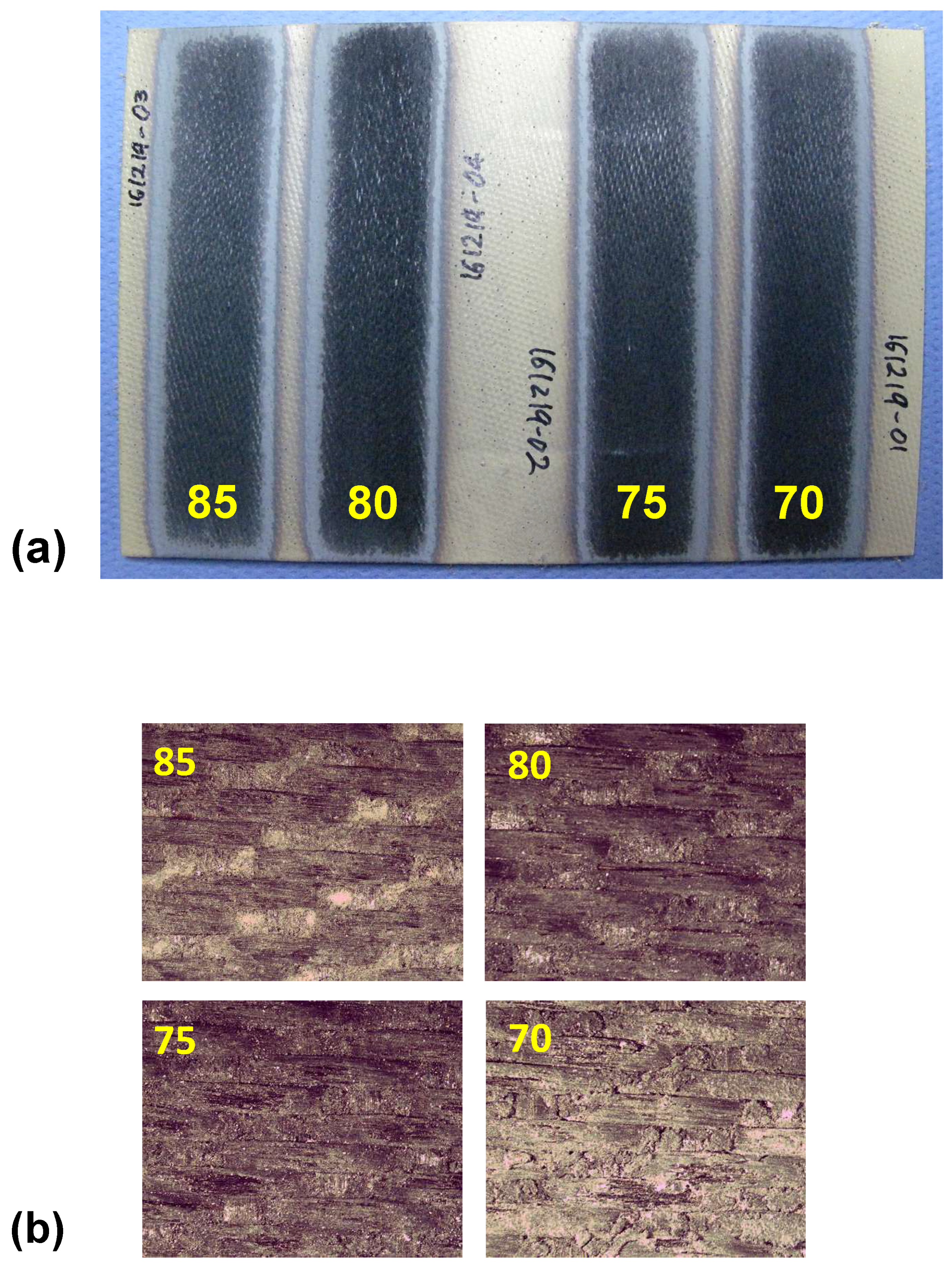
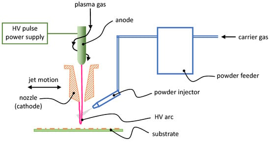
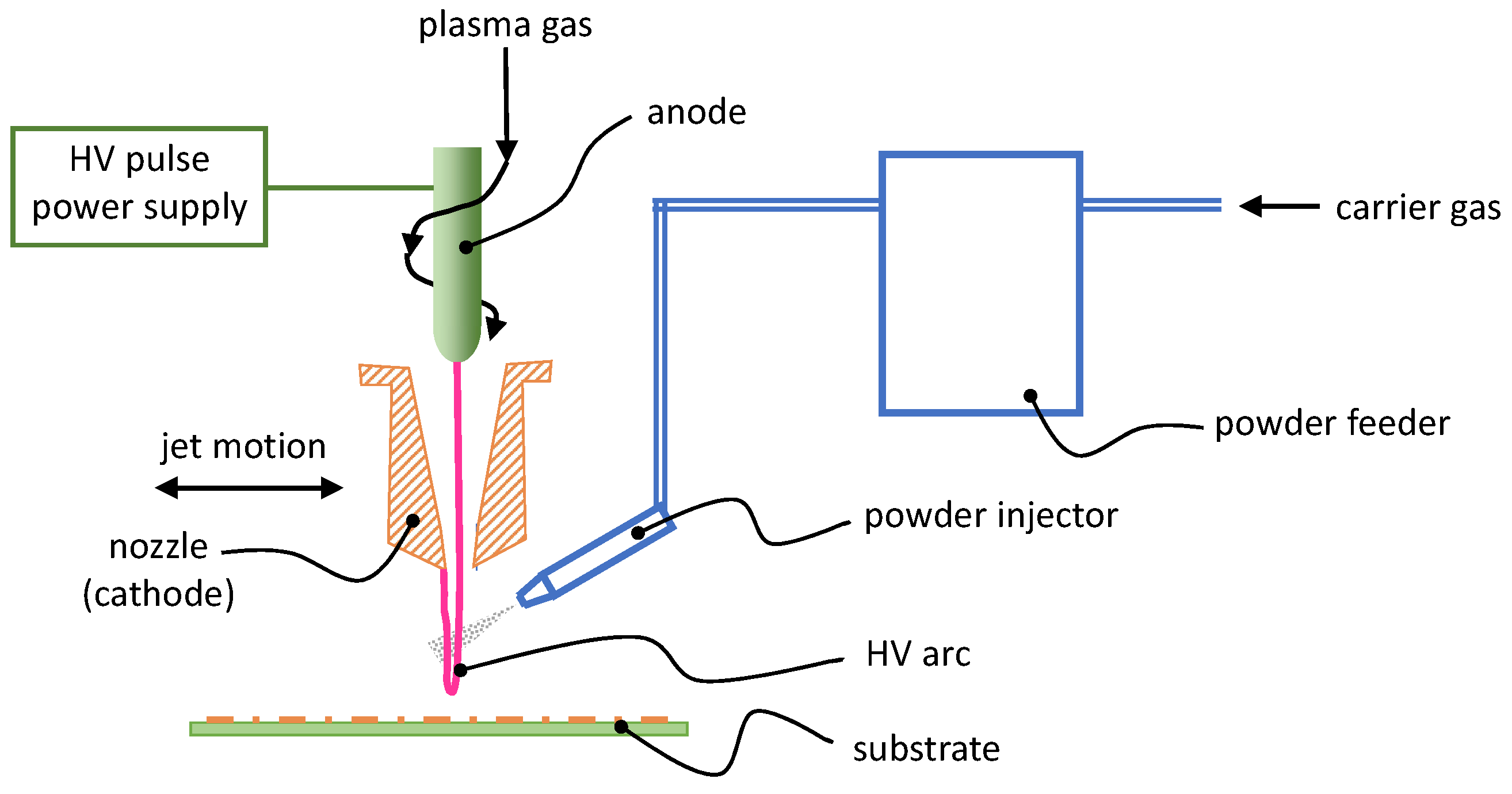
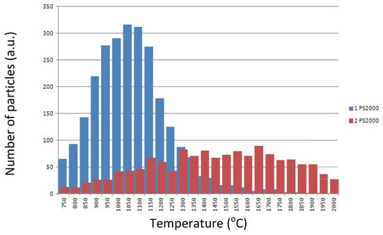
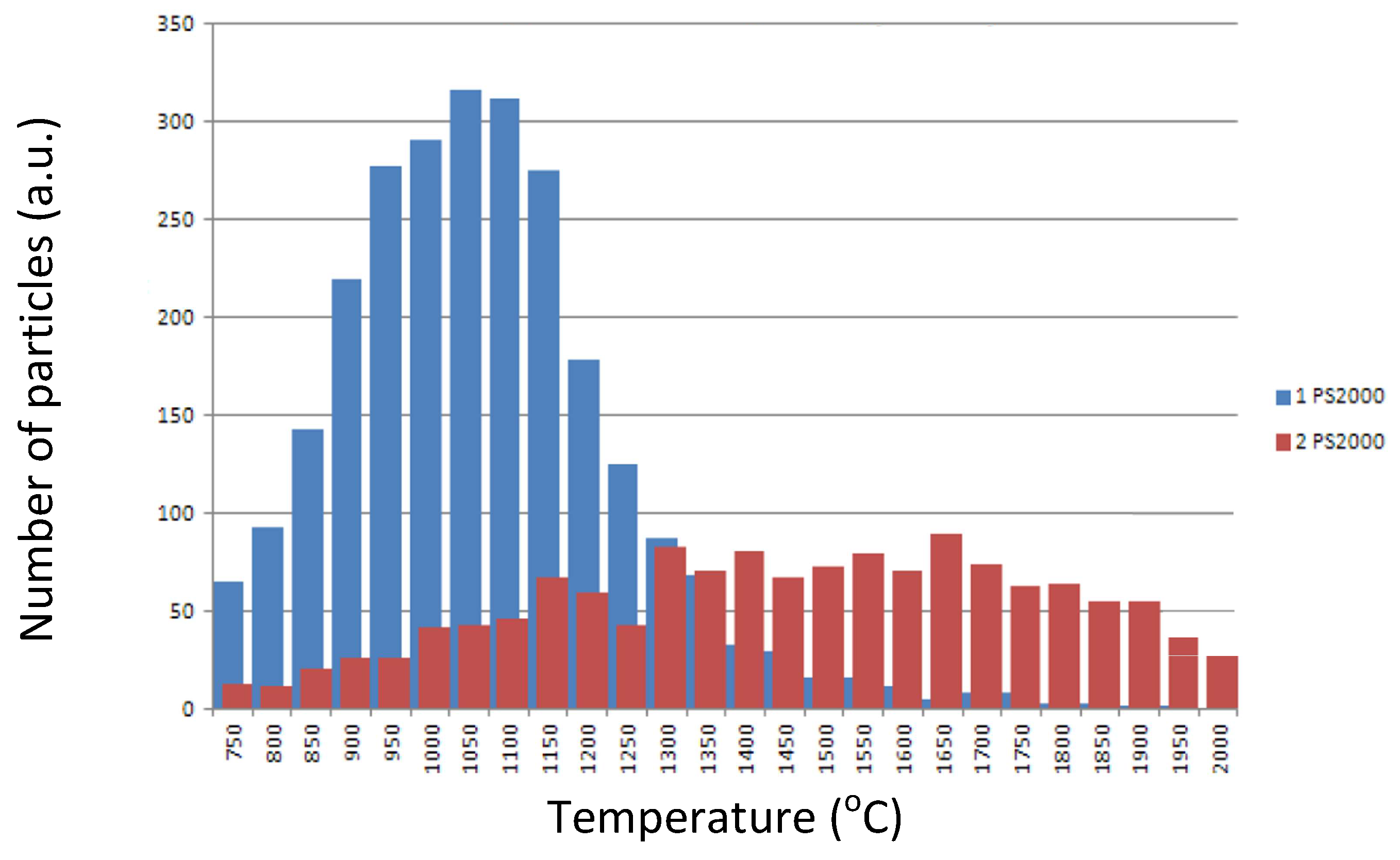
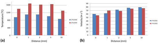
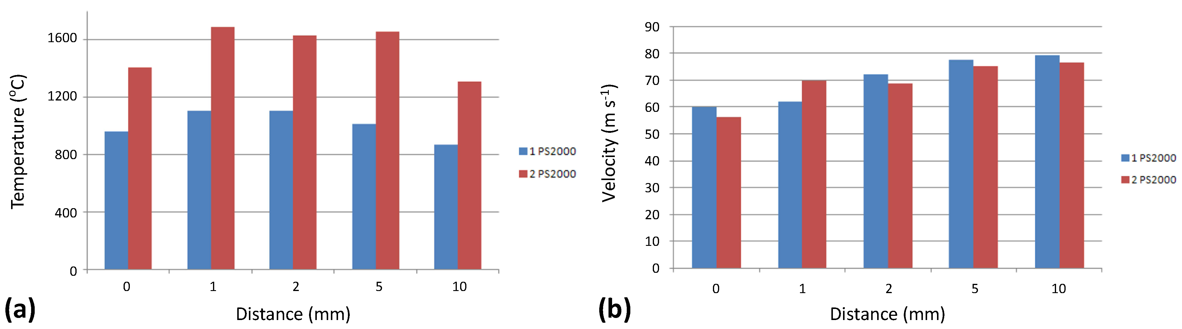
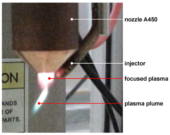
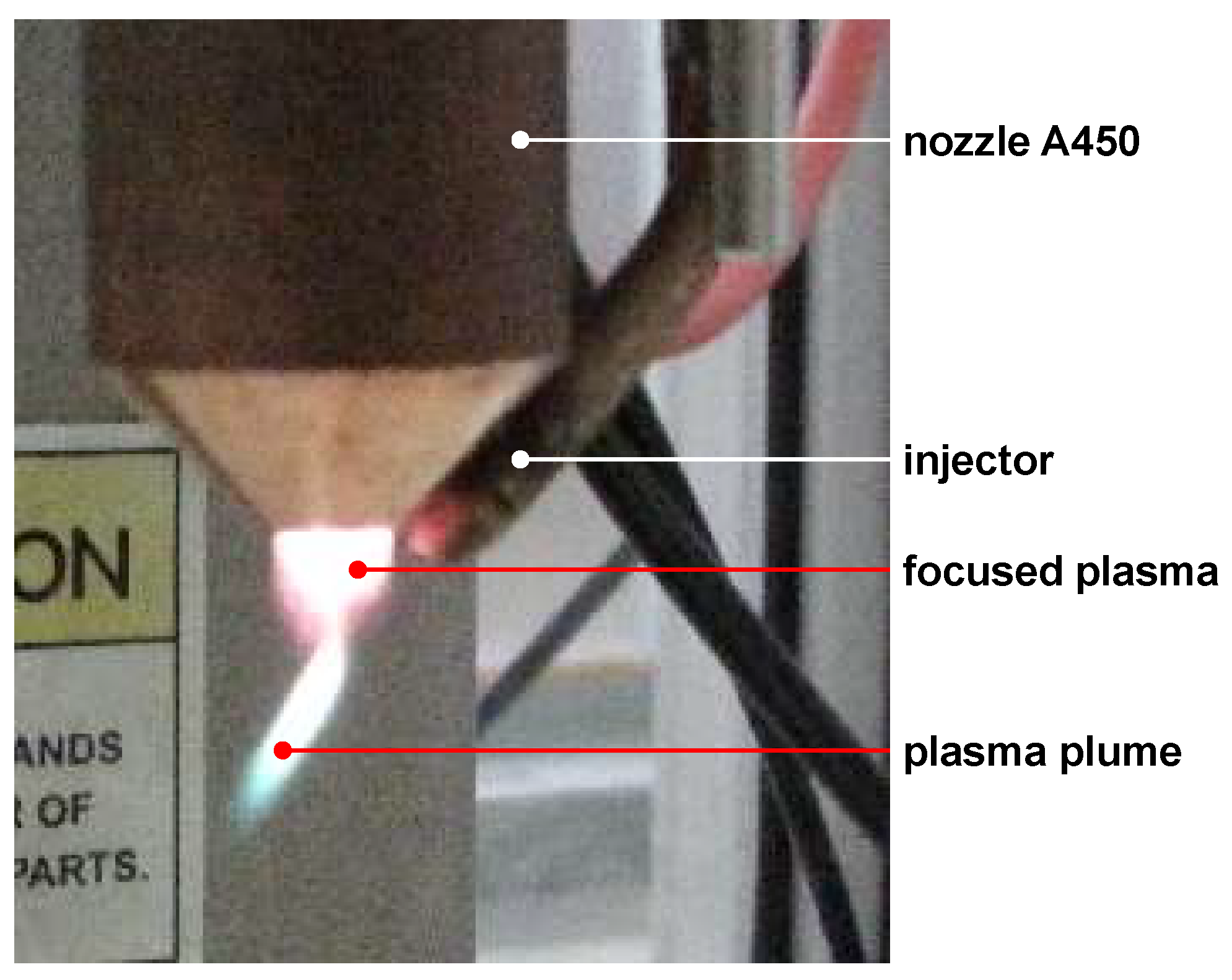

Disclaimer/Publisher’s Note: The statements, opinions and data contained in all publications are solely those of the individual author(s) and contributor(s) and not of MDPI and/or the editor(s). MDPI and/or the editor(s) disclaim responsibility for any injury to people or property resulting from any ideas, methods, instructions or products referred to in the content. |
© 2026 by the authors. Licensee MDPI, Basel, Switzerland. This article is an open access article distributed under the terms and conditions of the Creative Commons Attribution (CC BY) license.