Abstract
The fabrication of semiconductor devices with three-dimensional architectures imposes unprecedented demands on advanced plasma dry etching processes. These include the simultaneous requirements of high throughput, high material selectivity, and precise profile control. In conventional reactive ion etching (RIE), fluorocarbon plasma provides both accelerated ion species and reactive neutrals that etch the feature front, while the CFx radicals promote polymerization that protects sidewalls and enhance selectivity to the amorphous carbon layer (ACL) mask. In this work, we present computational results on the role of CF4 addition to hydrogen fluoride (HF) plasma for next-generation RIE, specifically cryogenic etching. Simulations were performed by varying the CF4 concentration in the HF plasma to evaluate its influence on ion densities, neutral species concentration, and electron density. The results show that the densities of CFx (x = 1–3) ions and radicals increase significantly with CF4 addition (up to 20%), while the overall plasma density and the excited HF species remain nearly unchanged. The results of plasma density and atomic fluorine density are consistent with the experimental observations of the HF/CF4 plasma using an absorption probe and the actimetry method. It was verified that the gas-phase reaction model proposed in this study can accurately reproduce the plasma characteristics of the HF/CF4 system. The coupling of HF-based etchants with CFx radicals enables polymerization that preserves SiO2 etching throughput while significantly enhancing etch selectivity against the ACL mask from 1.86 to 5.07, with only a small fraction (~10%) of fluorocarbon gas added. The plasma simulation provides new insights into enhancing the etching performance of HF-based cryogenic plasma etching by controlling the CF2 radicals and HF reactants through the addition of fluorocarbon gases.
1. Introduction
The continuous progress of modern technology, driven by the demand for smaller and more-portable electronic devices, has made improving the performance and efficiency of scaled electronic systems a primary focus of the semiconductor industry. As semiconductor devices are pushed into the nanoscale regime, the limitations of conventional planar scaling have become increasingly difficult to overcome. To address these challenges, device architectures have evolved toward three-dimensional heterogeneous structures, enabling further scaling and performance gains in integrated circuits, as demonstrated by innovations such as 3D NAND and 3D DRAM [1,2,3]. In these 3D structures, contact channels are essential for establishing electrical connections between stacked layers. The fabrication of advanced devices requires the formation of high-aspect-ratio channels that penetrate the alternating layers by using dry plasma etching.
Conventional RIE utilizing fluorocarbon gases for dielectric etching implies a high bias voltage on the substrate and fluorocarbon gases to facilitate the transport of positive ions to the bottom of the high-aspect-ratio channel holes [4,5,6,7,8]. However, the transport of the neutral radicals to the etching front end has become increasingly challenging due to the physical limitation of Knudsen diffusion [9,10]. Consequently, the decoupling between the ions and neutral radicals leads to a reduction in etch rate with increasing feature aspect ratio. In response to this requirement, a low-temperature or cryogenic process using HF gas as a precursor instead of fluorocarbon has been proposed for high-aspect-ratio etching and atomic layer etching (ALE) [11,12]. It has been reported that the HF reactants enable new synergistic reactions between ions and physisorbed/chemisorbed species, significantly reducing the surface charging effect and improving the etch rate of SiO2 [13,14,15,16]. Recently, Hsiao et al., reported the etching mechanism of SiO2 with cryogenic HF plasma, in which the synergy between ion-enhanced surface autocatalytic reactions and reduced etching activation energy caused by H2O by-products adsorbed on the cooled surface enables ultra-high etching throughput [17]. In numerical simulations, the surface reactions between HF and SiO2 have also been investigated at the atomic and molecular levels through density function theory [18]. Regarding gas-phase reactions, we have reported plasma simulations of dual-frequency excited HF plasmas [19].
ACL is often employed as a hard mask material for RIE of Si-based materials due to its high etching durability, making it particularly valuable for advanced semiconductor applications such as 3D NAND structures [20,21,22,23]. In conventional RIE process employing such plasmas, dielectric materials, including SiO2 and SiN, can exhibit etch selectivities over ACL exceeding 10, even under high bias voltages [21,24,25,26]. The selectivity can be effectively tuned by adjusting the feed gas chemistry to control the balance between CFx radical concentrations and atomic F density [24,27]. The etching characteristic of ACL is governed by the competing effects of plasma polymerization, which suppresses etching, and of atomic fluorine-induced chemical reactions, which enhance it [28]. However, a trade-off arises between selectivity and etching throughput of dielectric materials, as the etch rate increases with atomic fluorine density and decreases with increased fluorocarbon deposition [29,30]. In the case of pure HF plasma, the etching durability of ACL is expected to be low because carbon can readily react with H and F radicals to form volatile by-products such as CHx and CFx molecules, and plasma-induced polymerization is largely absent. Therefore, introducing fluorocarbon gas into HF plasma is expected to enhance the selectivity of SiO2 over ACL. To date, no studies including simulation and experiments have reported the influence of fluorocarbon addition to HF plasma on gas-phase composition during plasma discharge or the resulting etching selectivity between SiO2 and ACL. In our previous study, we proposed and experimentally validated a reaction model for HF plasma [19]. In this work, we propose a gas-phase reaction model for simulating HF/CF4 plasma and investigate the effect of CF4 addition on the evolution of gas-phase species in HF plasma using plasma simulation and verify its validity through comparison with experimental results. The establishment of such a reaction model capable of reproducing the actual HF/CF4 plasma, together with its integration into plasma simulations, provides fundamental insights into the SiO2 etching mechanism in HF/CF4 plasmas. To validate the simulated results, plasma diagnostics—including absorption probe and optical emission actinometry for the HF/CF4 plasma—were performed for HF/CF4 plasmas. The gas-phase reaction model was constructed based on previously reported collision cross-section and reaction rate constants and further calibrated using the experimental results. The simulation results indicate that the densities of CFx (x = 1–3) ions and radicals increase markedly with CF4 addition up to approximately 20% and then exhibit a slower rise up to 50% of CF4. Meanwhile, the overall plasma density and the concentration of excited HF species remain nearly unchanged. The plasma density is consistent with experimental measurements of HF/CF4 through the plasma diagnostic technique. The interaction between HF-based etchants and CFx radicals promotes polymerization, which maintains the SiO2 etching rate while significantly improving etch selectivity against the ACL mask (experimentally, from two to five), even with the addition of only a small fraction (~10%) of CF4 gas.
2. Methods
2.1. Simulation Model
2.1.1. Geometric Model and Boundary Conditions
As illustrated in Figure 1, the simulation model utilizes half of the cross-section of the capacitively coupled plasma (CCP) reactor. The central axis of the chamber was defined as the origin of a cylindrical system, with the vertical direction designated as the z-axis and the radial direction as the r-axis. With this framework, the position of the absorption probe for the plasma density measurement corresponded to z = 55 mm. The boundary conditions of the simulation were set to match the design of the actual reactor used for the experiments. HF/CF4 gas was uniformly introduced from the upper electrode and exhausted through a gap between the edge of the lower electrode and the quartz inner wall of the reactor. The process gas with the HF and CF4 mixture was supplied at a flow rate of 50 sccm, and the pressure during plasma discharge was set at 4 Pa. The relative dielectric constants of the insulating materials were set to 8.0 for Al2O3 and 4.0 for quartz. Sinusoidal RF powers of 300 W at 100 MHz and 200 W at 2 MHz were applied to the upper and lower electrodes, respectively, with both waves initiated at 0° phase. All metallic surfaces—excluding the two electrodes—such as the reactor chamber walls, were set at ground potential. The geometrical potential simulation model was calibrated against the experimentally measured electron density of CF4 plasma, with deviation constrained to within ±5% [31].
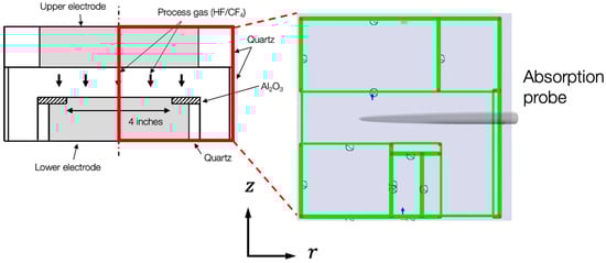
Figure 1.
Two-dimensional simulation model in r- and z-axis cylindrical coordinates. The schematic of absorption probe for plasma density measurement is illustrated. The arrow below the upper electrode represents the flow direction of the process gas from the electrode.
2.1.2. Plasma Simulation
The plasma simulation was performed used the plasma hybrid module (PHM) provided by a commercial software, PEGASUS PHM ver. 20250712 (PEGASUS Software Inc., Tokyo, Japan). The PHM is a fluid model simulator with the continuity equation of electrons expressed as
where is the electron density; is the electron flux; and is the electron production rate. Similarly, the continuity equation of positive ions is given as
where is the ion density; is the ion flux; and is the ion generation rate. The previous simulation studies have demonstrated that incorporating the effect of secondary electron emission is essential for improving simulation accuracy. In plasma simulations, the definition of boundary conditions is a critical factor influencing accuracy and stability. In this study, the boundary conditions were defined as follows: positive ions, electrons, and excited species (HF(v)) were assumed to be lost at the electrode surfaces, while neutral species were reflected at the surfaces. In plasma simulation of RIE systems, secondary electrons emitted from the electrodes upon ion bombardment play a particularly important role. In our previous work, the secondary electron emission coefficient for the dual-frequency excitation system was used as 0.07 based on combined experimental and simulation analyses [32]. Accordingly, in the present calculation, a secondary electron emission coefficient of 0.07 was applied to both the upper and lower electrodes.
2.1.3. Coupled Calculation of Plasma and Gas Flow Simulations
The diffusion and flow of neutral particles were calculated using the neutral momentum equation (NMEM) module of PEGASUS. In NMEM, the continuity equation of Equation (3) was solved to determine the distribution of gas flow velocity [33,34,35] as follows:
where is the gas density, and is time. and are the velocities in the r- and z-axes, respectively. In the coupled calculation of plasma and gas flow, the gas reaction was calculated in the plasma simulation, and the generated particles including neutral particles were reflected in the flow simulation. The continuity equation in the coupled calculation is expressed as
where is the mass density of a-type particles, and is the number of a-type particles generated and lost per unit time and unit volume. The value calculated by the plasma simulation was reflected in . In the gas state in which the movement of various particles was calculated, the calculation of particles generated in the plasma was performed again. The calculations were repeated until the density change of each particle between the current and the previous calculation converged below a set value.
2.1.4. Gas-Phase Reaction Models
The gas-phase reaction models related to HF gas in the plasma simulation are summarized in Table 1, including electron impact, collision cross-sections, and reaction constants [36,37,38,39,40,41]. The reaction rate of G5 was calibrated to reproduce the experimental results reported previously [19]. In the table, estimated values indicate cases in which collision cross-sections were assumed. For reactions G7 and G8, vibrationally excited HF molecules (v = 1 and v = 2) [38] are ionized to HF+. Since no experimental reports of cross-sections are available for these reactions, the following assumption was made: while the collision cross-sections of G3 and G4 are valid below 2 eV, ionization in G2 occurs above 10 eV. Thus, to ionize vibrationally excited HF (v = 1 and v = 2) to H+, an energy of at least 10 eV must be transferred from electrons. Accordingly, the same cross-section as that of the HF ionization reaction G2 was applied. Furthermore, the CF4 reaction model in the plasma simulation was developed with the published results [31]. Momentum transfer, dissociation, and ionization reactions due to electron–CF4 collisions were incorporated. The resulting species, including CF3+, CF2+, CF+, CF3, CF2, CF, and F, were added to the simulation model [42,43,44,45,46]. Table 2 summarizes the gas-phase reactions included in the CF4 reaction model. The interactions between products generated from CF4 and HF are considered as follows: The dissociation of HF generates H atomic radicals, which then react with the F atoms produced from CF4 dissociation. Their reactions are included in the HF gas model as reactions G15–G17, and thus no additional models are required. As reported in the previous literature, reactions between CFx (x = 1–3) and H to form CHF3 and CH2F2 proceed with reaction rates that are two orders of magnitude lower than those between CFx and F [47]. Therefore, in the present simulation model, reactions between CFx and H were considered minor and thus negligible. This is presumed to be due to the much higher reactivity of F compared with H.

Table 1.
Gas-phase reactions for H and F related species.
Table 2.
Gas-phase reactions for fluorocarbon-related species.
2.2. Experimental Procedures
As described in Section 2.1.1, a home-built CCP reactor was used to perform the HF/CF4 plasma discharge and the etching of the SiO2 and ACL films. The upper and lower electrodes were of 150 and 100 mm diameter, respectively, with an electrode spacing of 30 mm. The upper electrode was made of silicon, while the lower electrode was electrically insulated from the chamber ground by Al2O3 and quartz. The upper and lower electrodes were connected to RF power sources at 100 and 2 MHz, respectively. Prior to the experiment, the base pressure was reduced to below 4 × 10⁻⁴ Pa. A HF/CF4 gas mixture was introduced at a constant flow rate of 50 sccm through a showerhead integrated into the upper electrode. During plasma discharge, the pressure was maintained at 4 Pa using an automatic pressure controller.
The plasma electron density was measured using a plasma absorption probe (PAP, homemade) [48,49]. The probe consisted of an internal antenna with a diameter of 0.5 mm enclosed in a quartz tube with an outer diameter of 4 mm and was inserted into the plasma through a chamber port, as illustrated in Figure 1. The probe tip was positioned at the chamber center, midway between the upper and lower electrodes. RF powers of 300 W and 200 W were applied to the upper and lower electrodes, respectively. The CF4 gas mixing ratio was varied from 0 to 50%, and the corresponding electron density was measured. To further validate the proposed simulation model, the relative atomic fluorine density in HF/CF4 plasmas was measured by optical actinometry based on optical emission spectroscopy. The relative fluorine density was obtained by comparing the relative emission intensity of the F line with that of Ar, as an actinometer. Detailed descriptions regarding the method, setup, and theoretical background are provided in the other publications [14,50].
The SiO2 and ACL sample were deposited by plasma-enhanced chemical vapor deposition on the Si substrate and prepared as 20 mm × 20 mm squares, which were then mounted on a Si carrier wafer. Prior to the etching experiments, the PAP was removed. The substrate temperature was controlled using a circulated coolant system. The etching rate of the sample during the use of CF4/HF plasmas was determined from film thickness variations monitored by in situ spectroscopic ellipsometry (J.A. Woollam Co., Inc. M-2000F, Lincoln, OR, USA). Further details regarding the reactor, sample property, and experimental setup can be found elsewhere [17,25].
3. Results
The effect of varying the CF4 concentration from 0 to 50% on the density of the gas species generated by CF4/HF plasma was analyzed via the plasma simulation. Figure 2 presents a representative example of the simulation results at a CF4 concentration of 10%. Even with 10% CF4 addition, the distribution function (see Supporting Information Figure S1) does not change significantly. However, CF4 addition leads to a slightly higher distribution for HF/CF4 than that with HF, with a maximum increase of approximately 0.06 in the electron energy range around 2.5 eV and up to about 0.01 in the energy range above 2.5 eV. The spatial distributions of electron density and CF3 radical density are shown in Figure 2a and Figure 2b, respectively. These results indicate that both the electron and CF3 density are nearly uniform within a radical range of 50 mm from the reactor center, where a 100 mm wafer is located. To validate the simulation results, the spatial distribution of the electron density of the plasma with a CF4 concentration of 10% is compared with the experimental results using PAP. As illustrated in Figure 3, both simulation and experimental results show that the electron density remained nearly uniform within 40 mm of the chamber center, with a slight decrease observed toward the bottom electrode edge. The spatial uniformity of electron density was measured as ±6.2% in the simulation. The close agreement in the electron density distribution up to 50 mm further confirms the validity of the simulation.
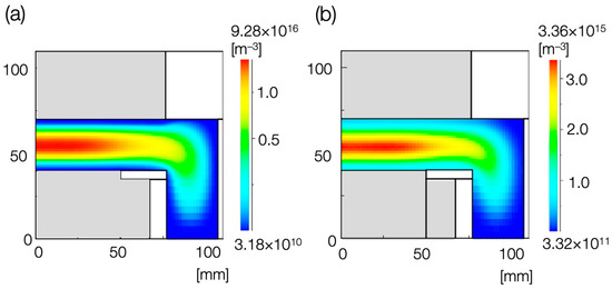
Figure 2.
A representation of the results of plasma etching with CF4/(CF4 + HF) = 10%. Spatial distribution of (a) electron density and (b) CF3 radical density.
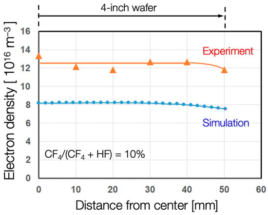
Figure 3.
Simulated and measured spatial distribution of the plasma density in the HF/CF4 plasma with CF4 concentration of 10%.
Although the simulated and experimental results exhibit similar trends, a clear discrepancy is observed in their absolute magnitudes. The difference in these electron densities could be primarily attributed to two factors: (i) systematic error for the PAP measurement and/or (ii) an underestimation of the collisional cross-section used in the simulation. The former case is less likely, as the uncertainty in determining the electron density with PAP arises from measurement errors in the absorption frequency, which primarily depends on the antenna length and the air–core region of the co-axial cable [51]. In this study, the co-axial cable was carefully installed to ensure the acquisition of a sharp absorption peak, as shown in the published literature [52]. Therefore, the later explanation is more plausible. As mentioned in Section 2.1.4, the collision cross-sections for G7 and G8 reactions have not been reported, and the same values as those for G2 were used, where HF ionization is required. However, in the cases of G7 and G8, HF (v = 1) and HF (v = 2) are vibrationally excited, and their cross-sections are expected to be larger than the HF collision cross-section of G2. Since HF (v = 1) and HF are generated through collision between HF (v = 2) and electrons, their combined density at a CF4 concentration of 10% was 3.26 × 10¹⁷ m−3. In contrast, the total HF density is 8.64 × 10²⁰ m−3, which is more than three orders of magnitude higher. Therefore, even if the cross-sections of G7 and G8 vary, their influence on HF+ and electron density is negligibly small, and their overall effect on the CF4 gas-phase reactions can be regarded as insignificant. Using the cross-sections reported in previous studies, the electron density is still calculated to be slightly lower than the experimentally measured value. Therefore, the lower electron density cannot be fully explained solely by the assumption that the currently reported cross-section set underestimates the G7 and G8 cross-sections. Another possible factor is the loss of positive ions and electrons at the chamber surface, which is defined as a boundary condition in the simulation. In the present calculation, it was assumed that all positive ions and electrons are completely lost upon reaching the chamber surface; however, in reality, only a fraction of them may be lost, suggesting that the assumed loss conditions could contribute to the underestimation of the electron density.
Figure 4 presents the simulated and measured electron densities at the same position of the probe measurement as a function of CF4 concentration (0 to 50%) in the HF/CF4 plasmas. The simulated density of negative F− is also included. As the CF4 concentration increases, the electron density remains nearly constant, with an average value of 7.78 × 10¹⁶ m−3. This behavior is primarily attributed to the similar electron-impact ionization cross-section of HF and CF4 [53,54]. Furthermore, the measured electron densities of the pure HF (~1.4 × 10¹⁶ m−3) and CF4 plasmas (~1.2 × 10¹⁶ m−3) are also comparable [19,31], which also supports the observation. A comparison between the simulated and measured results shows consistent trends, as illustrated in Figure 4, supporting the validity of the simulation. Furthermore, the electron density is several orders of magnitude higher than that of negative F−, indicating the electrons and positive ions dominate the plasmas. This behavior is attributed to the use of ultra-high-frequency CCP (100 MHz) with a high power input (300 W), where electron attachment is expected to be low under continuous-wave plasma operation [55]. In this context, the secondary electron emission coefficient is determined by the ions striking the electrodes: in pure HF plasmas, HF+ ions dominate, whereas the fraction of CFx+ increases with CF4 addition. Since CFx+ ions are heavier than HF+, the secondary electron emission coefficient could potentially be higher. However, because the electron density remains unchanged with varying CF4 partial pressure, it is inferred that the secondary electron emission coefficient is effectively unaffected by CF4 addition.
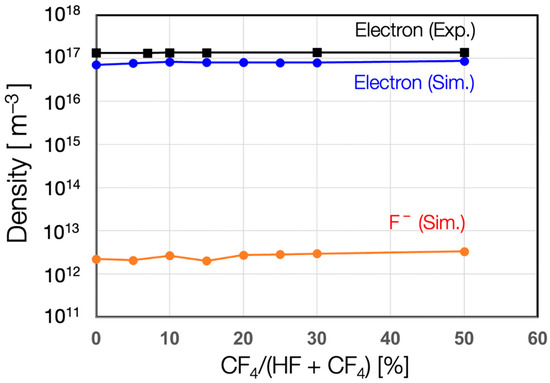
Figure 4.
Dependence of measured electron density and simulated electron and negative ion densities on CF4 concentration in the HF/CF4 plasmas.
Figure 5 illustrates the positive ion density and neutral radical density, extracted from the value at the center position between the electrodes, as a function of CF4 concentration (0–50%) in HF/CF4 plasmas. As illustrated in Figure 5a, the total positive ions remain nearly constant, indicating insensitivity to CF4 addition, which is consistent with the nearly unchanged electron density observed in Figure 4. At a CF4 addition of 10%, the electron density was 7.78 × 10¹⁶ m−3, while the total positive ion density shown in Figure 5a is 7.89 × 10¹⁶ m−3, indicating good agreement between them. Plasma is primarily sustained through collisions between electrons and neutral species, which generate positive ions and additional electrons; hence, the positive ion and electron densities are expected to be nearly identical. The close agreement between these densities in the simulation confirms the validity of the computational results. As the CF4 addition is less than 20%, only a small decrease in the HF+ and H+ densities is observed. Subsequently, the density reduction becomes more significant as CF4 addition is increased from 20 to 50%. Conversely, the densities of CFx ions (x = 1–3) exhibit an opposite trend. The variations are more significant for the neutral radical density, as shown in Figure 5b. As the CF4 concentration increases from 0 to 50%, the densities of excited HF(v), including HF (v = 1 and v = 2), remained almost unchanged, and the H density monotonically decreased. This behavior might be attributed to the reactions G16 and G17, supported by the significantly increased density of F when CF4 is added. Furthermore, the densities of CFx (x = 1–3) neutral radicals increase rapidly with CF4 addition up to 20% and then increase more-gradually with further addition, similar to the behavior observed in the fluorocarbon/H2 plasmas [56]. To validate the radical densities obtained from the simulated results, OES actinometry was performed. As illustrated in Figure 6, the relative atomic F densities from both the simulation and experiment exhibit a very similar trend, confirming the validity of the proposed model.
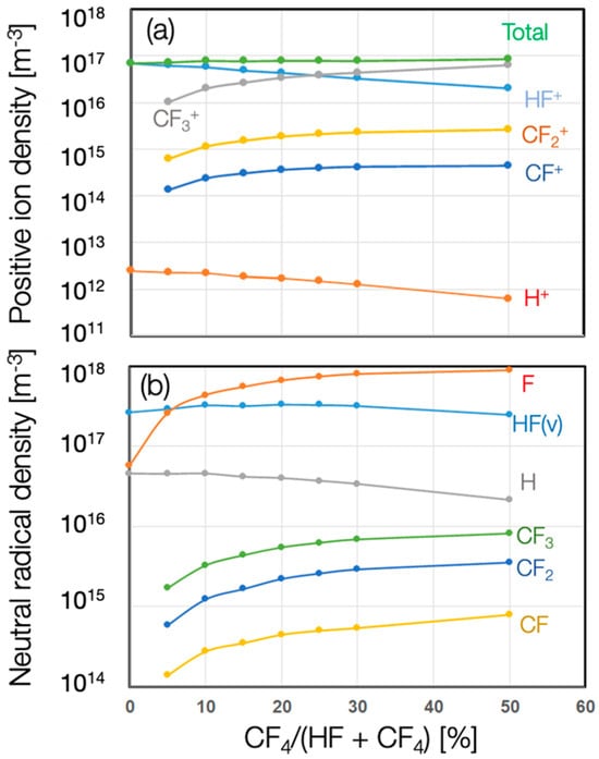
Figure 5.
Dependence of (a) positive ion density and (b) neutral radical density on CF4 concentration in HF/CF4 plasmas.
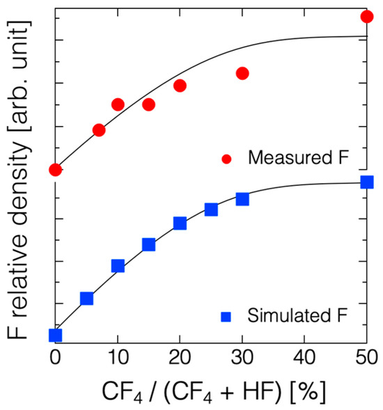
Figure 6.
Dependence of relative F density obtained by measurement and simulation on CF4 concentration in HF/CF4 plasmas.
4. Discussion
During the etching of SiO2 patterns with an ACL mask, controlling etching selectivity is of importance. In conventional RIE using fluorocarbon-based plasmas, the balance between etching and polymerization is governed by the interactions among ions, F atoms, and fluorocarbon radicals. Fluorocarbon deposition not only enhances anisotropic etching by protecting the feature side wall but also increases the SiO2/ACL selectivity, albeit often at the cost of a reduced SiO2 etch rate [26,57]. Accordingly, the durability of ACL under cryogenic HF plasma is expected to be low, since all generated ions and radicals (H- and F-related species) can etch the film. The addition of fluorocarbon to the HF plasma is expected to enhance the durability of ACL and thus improve the SiO2/ACL selectivity. Nevertheless, the reduced HF partial pressure results in a decrease in SiO2 etching, as HF gas itself is regarded as the primary etchant in the pseudo-wet mechanism of cryogenic HF plasma [14,17]. Furthermore, the CF3+ ion exhibits a higher etching yield for the ACL than F+ based on ion-beam etching experiments [28]. Consequently, a trade-off behavior between throughput and material selectivity, with a local maximum at moderate fluorocarbon addition, can be anticipated.
As shown in Figure 5, the simulated results indicate a notable increase in the densities of CFx radical for polymerization with the addition of a small amount of fluorocarbon (<20%), while the density of HF in vibrationally excited states remains nearly unchanged. These results suggest a process window to gain the material selectivity of SiO2/ACL with a small amount of CF4 addition. To verify these suggestions, the SiO2 and ACL films were experimentally etched by the HF/CF4 plasmas at a cryogenic temperature (−60 °C), as shown in Figure 7a. The etch rates of SiO2 and ACL and their selectivity are a function of CF4 concentration in the HF/CF4 plasmas. The results clearly indicate a local minimum of ACL etching, as only 10% of CF4 was added. On further adding CF4 into the HF plasma, the increase in the etch rate is probably attributed to the greater number of CF3+ ions, with a higher etching yield for ACL under higher atomic fluorine density [28]. On the other hand, the etch rate for SiO2 remained nearly unchanged, as the CF4 increased from 0 to 20%. As a consequence, a local maximum in SiO2/ACL selectivity, increased from 1.86 to 5.07, is obtained for the HF/CF4 plasma with 10% CF4. For the process at 20 °C, the selectivity increased only slightly from 0.5 to approximately 1 with the addition of 7% CF4, after which it remained nearly constant for further increases in CF4 content. Based on the simulated results, the etching behaviors of SiO2 could be attributed to the following factors: (i) an increase in CFx+ (x = 1–3) ion and F atomic densities, (ii) the presence of vibrationally excited HF molecules with nearly constant density, and (iii) the reduced partial pressure of HF. In conventional RIE, the CF3+ ions exhibit a high etching yield for SiO2 and ACL etching as F is sufficiently high; however, the polymerization caused by CFx radicals may also hinder the etching [58]. When the bias voltage is higher, CFx ions are likely to penetrate the thin fluorocarbon deposited on the SiO2 and ACL, leading to higher etch rates for both ACL and SiO2 and a relatively low selectivity, consistent with the findings in Figure 7b and previous studies [26,29,59]. Moreover, the CF2-to-F radical fraction has been reported as a key factor determining etching behavior in C4F8/Ar/O2 plasma based on hybrid model simulations [60]. In contrast, for HF-based plasma at cryogenic temperature, the primary etchants shift from CF ions and F radicals to HF molecules and their excited states, while the increased sticking coefficient of radicals at low temperatures contributes to enhanced selectivity [61,62]. Additionally, as reported by Volynets et al., vibrationally excited HF molecules could play a role in etching SiN at room temperature, which could have an even greater impact at cryogenic temperatures. Although the partial pressure of HF is expected to be reduced by a factor of two, the density of the vibrationally excited HF remains nearly unchanged. This may explain why only a small reduction (~18%) in the SiO2 etch rate is observed, assuming the primary etchant is HF-related species rather than CFx ions. The interactions between ions, CF radicals, and HF surface absorption are complex and require further investigations using surface characterization techniques, which is beyond the scope of this paper.
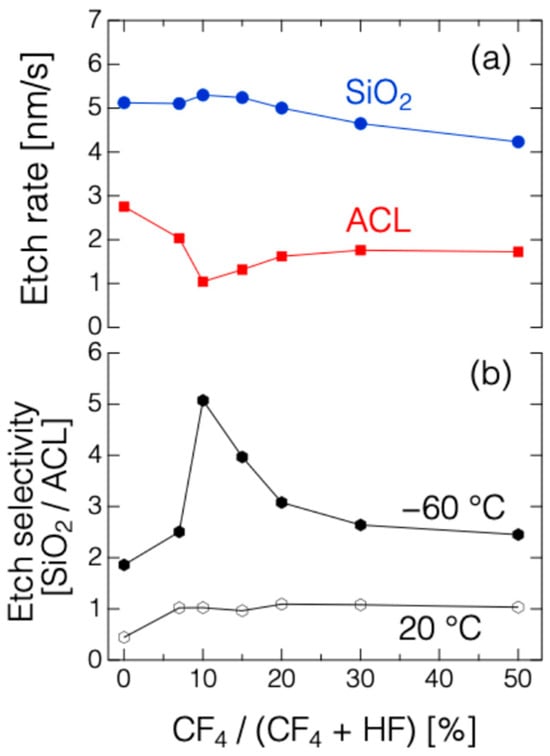
Figure 7.
Dependence of (a) etch rate of SiO2 and ACL and (b) selectivity of SiO2/ACL on the CF4 concentration in HF/CF4 plasma at 20 and −60 °C.
5. Conclusions
The effects of CF4 addition on the gas-phase species in the HF plasma for cryogenic etching of SiO2 and ACL films were investigated through plasma simulations constructed using collision cross-sections and reaction constants from our previous works. The simulations indicate that the overall plasma density remains nearly unchanged as the CF4 addition increases from 0 to 50%, consistent with the experimental measurements obtained using a plasma absorption probe. The increase in CFx (x = 1–3) neutral radical density, which contributes to polymerization, suggests a process window for enhancing etching selectivity between SiO2 and ACL by adding a small amount of CF4 to the HF plasma. This finding is supported by experimental results obtained at −60 °C, in which the addition of only 10% CF4 increased the selectivity of SiO2/ACL from 1.86 to 5.07, without compromising the SiO2 etch rate. The findings suggests that the simulation framework could be extended to other fluorocarbon precursors, such as C2F6, C4F8, as well as alternative chemistries with low global-warming potentials (GWPs), such as C6F6, C3H2F6, and CF3CHCF2 [27,63,64,65], to further advance the sustainable development goals of semiconductor manufacturing.
Supplementary Materials
The following supporting information can be downloaded at https://www.mdpi.com/article/10.3390/plasma8040048/s1: Figure S1: Electron energy probability function of the HF and HF/CF4 plasmas with 10 % CF4 addition.
Author Contributions
Conceptualization, S.T. and S.-N.H.; Methodology, S.T. and S.-N.H.; Software, F.M.; Validation, S.T. and M.S.; Formal analysis, S.T., S.-N.H. and Y.I.; Investigation, S.T. and S.-N.H.; Resources, S.T., M.S. and F.M.; Data curation, S.T., S.-N.H. and Y.I.; Writing—original draft, S.T. and S.-N.H.; Writing—review and editing, S.T., S.-N.H. and M.S.; Visualization, S.T. and S.-N.H.; Supervision, M.S.; Project administration, M.S.; Funding acquisition, M.S. All authors have read and agreed to the published version of the manuscript.
Funding
This research received no external funding.
Institutional Review Board Statement
Not applicable.
Informed Consent Statement
Not applicable.
Data Availability Statement
The original contributions presented in this study are included in the article/Supplementary Material. Further inquiries can be directed to the corresponding author.
Acknowledgments
This work was carried out by the joint usage/research program of the Center for Low-Temperature Plasma Sciences, Nagoya University.
Conflicts of Interest
Author Fumihiko Matsunaga was employed by the company PEGASUS Software Inc. The remaining authors declare that the research was conducted in the absence of any commercial or financial relationships that could be construed as a potential conflict of interest.
References
- Goda, A. 3-D NAND Technology Achievements and Future Scaling Perspectives. IEEE Trans. Electron. Devices 2020, 67, 1373–1381. [Google Scholar] [CrossRef]
- Jayachandran, D.; Sakib, N.U.; Das, S. 3D integration of 2D electronics. Nat. Rev. Electri. Eng. 2024, 1, 300–316. [Google Scholar] [CrossRef]
- Choi, K.S.; Kim, S.H.; Seo, J.W.; Kang, H.S.; Chu, S.W.; Bae, S.W.; Kwon, J.H.; Kim, G.S.; Park, Y.T.; Kwak, J.H.; et al. A Three Dimensional DRAM (3D DRAM) Technology for the Next Decades. In Proceedings of the 2024 IEEE Symposium on VLSI Technology and Circuits (VLSI Technology and Circuits), Honolulu, HI, USA, 16–20 June 2024; pp. 1–2. [Google Scholar]
- Ishikawa, K.; Karahashi, K.; Ishijima, T.; Cho, S.I.; Elliott, S.; Hausmann, D.; Mocuta, D.; Wilson, A.; Kinoshita, K. Progress in nanoscale dry processes for fabrication of high-aspect-ratio features: How can we control critical dimension uniformity at the bottom? Jpn. J. Appl. Phys. 2018, 57, 06JA01. [Google Scholar] [CrossRef]
- Cagomoc, C.M.D.; Isobe, M.; Hudson, E.A.; Hamaguchi, S. Molecular dynamics simulation of oxide-nitride bilayer etching with energetic fluorocarbon ions. J. Vac. Sci. Technol. A 2022, 40, 063006. [Google Scholar] [CrossRef]
- Chung, S.-J.; Luan, P.; Park, M.; Metz, A.; Oehrlein, G.S. Exploring oxide-nitride-oxide scalloping behavior with small gap structure and chemical analysis after fluorocarbon or hydrofluorocarbon plasma processing. J. Vac. Sci. Technol. B 2023, 41, 062201. [Google Scholar] [CrossRef]
- Krüger, F.; Lee, H.; Nam, S.K.; Kushner, M.J. Voltage waveform tailoring for high aspect ratio plasma etching of SiO2 using Ar/CF4/O2 mixtures: Consequences of low fundamental frequency biases. Phys. Plasmas 2024, 31, 033508. [Google Scholar] [CrossRef]
- Nishizuka, T.; Igosawa, R.; Yokoyama, T.; Sako, K.; Moki, H.; Honda, M. Precise and practical 3D topography simulation of high aspect ratio contact hole etch by using model optimization algorithm. J. Vac. Sci. Technol. A 2024, 42, 043003. [Google Scholar] [CrossRef]
- Huard, C.M.; Zhang, Y.; Sriraman, S.; Paterson, A.; Kushner, M.J. Role of neutral transport in aspect ratio dependent plasma etching of three-dimensional features. J. Vac. Sci. Technol. A 2017, 35, 05C301. [Google Scholar] [CrossRef]
- Gottscho, R.A.; Jurgensen, C.W.; Vitkavage, D.J. Microscopic uniformity in plasma etching. J. Vac. Sci. Technol. B 1992, 10, 2133–2147. [Google Scholar] [CrossRef]
- Kihara, Y.; Tomura, M.; Sakamoto, W.; Honda, M.; Kojima, M. Beyond 10 m Depth Ultra-High Speed Etch Process with 84 Lower Carbon Footprint for Memory Channel Hole of 3D NAND Flash over 400 Layers. In Proceedings of the IEEE Symposium on (VLSI Technology and Circuits), Kyoto, Japan, 11–16 June 2023; pp. 1–2. [Google Scholar]
- Hsiao, S.-N.; Sekine, M.; Iijima, Y.; Hori, M. In Situ Monitoring Surface Reactions in Cryogenic Atomic Layer Etching of Silicon Nitride by Alternating Surface Modification with Hydrogen Fluoride Dose and Ar Plasmas. Chem. Mater. 2024, 36, 11042–11050. [Google Scholar] [CrossRef]
- Hsiao, S.-N.; Sekine, M.; Ishikawa, K.; Iijima, Y.; Ohya, Y.; Hori, M. An approach to reduce surface charging with cryogenic plasma etching using hydrogen-fluoride contained gases. Appl. Phys. Lett. 2023, 123, 212106. [Google Scholar] [CrossRef]
- Hsiao, S.N.; Sekine, M.; Britun, N.; Mo, M.K.T.; Imai, Y.; Tsutsumi, T.; Ishikawa, K.; Iijima, Y.; Suda, R.; Yokoi, M.; et al. Pseudo-Wet Plasma Mechanism Enabling High-Throughput Dry Etching of SiO2 by Cryogenic-Assisted Surface Reactions. Small Methods 2024, 8, 2400090. [Google Scholar] [CrossRef]
- Lill, T.; Wang, M.; Wu, D.; Oh, Y.-J.; Kim, T.W.; Wilcoxson, M.; Singh, H.; Ghodsi, V.; George, S.M.; Barsukov, Y.; et al. Low-temperature etching of silicon oxide and silicon nitride with hydrogen fluoride. J. Vac. Sci. Technol. A 2024, 42, 063006. [Google Scholar] [CrossRef]
- Dussart, R.; Tillocher, T.; Becerra, L.; Lefaucheux, P.; Overzet, L.J. Cryogenic etching of SiOxFy and SiO2 in SF6/H2 plasma. Jpn. J. Appl. Phys. 2025, 64, 05SP01. [Google Scholar] [CrossRef]
- Hsiao, S.N.; Imai, Y.; Sekine, M.; Suda, R.; Iijima, Y.; Kihara, Y.; Ishikawa, K.; Hori, M. Revolutionizing reactive ion etching: Ion-enhanced surface autocatalytic reactions enabling ultra-high throughput using cryogenic hydrogen-fluoride plasma. Chem. Eng. J. 2025, 522, 167517. [Google Scholar] [CrossRef]
- Hidayat, R.; Kim, H.L.; Khumaini, K.; Chowdhury, T.; Mayangsari, T.R.; Cho, B.; Park, S.; Lee, W.J. Selective etching mechanism of silicon oxide against silicon by hydrogen fluoride: A density functional theory study. Phys. Chem. Chem. Phys. 2023, 25, 3890–3899. [Google Scholar] [CrossRef]
- Takagi, S.; Hsiao, S.-N.; Ma, C.-Y.; Sekine, M.; Matsunaga, F. Plasma simulation of HF plasma generated in dual-frequency chamber for high aspect ratio dielectric etching. Jpn. J. Appl. Phys. 2024, 63, 09SP21. [Google Scholar] [CrossRef]
- Kim, I.S.; Shim, C.E.; Kim, S.W.; Lee, C.S.; Kwon, J.; Byun, K.E.; Jeong, U. Amorphous Carbon Films for Electronic Applications. Adv. Mater. 2023, 35, e2204912. [Google Scholar] [CrossRef]
- Jiang, Z.; Zhu, H.; Sun, Q. Process Optimization of Amorphous Carbon Hard Mask in Advanced 3D-NAND Flash Memory Applications. Electronics 2021, 10, 1374. [Google Scholar] [CrossRef]
- Park, S.J.; Kim, D.; Baek, S.Y.; Lee, C.; Kim, J.; Roh, S.; Park, J.; Kyung, S.; Choi, C. Nitrogen doped high selectivity amorphous carbon film for high aspect ratio etch process. Thin Solid Film. 2025, 809, 140582. [Google Scholar] [CrossRef]
- Yeom, H.J.; Yoon, M.Y.; Choi, D.; Lee, Y.; Kim, J.H.; You, S.J.; Lee, H.C. Role of Oxygen in Amorphous Carbon Hard Mask Plasma Etching. ACS Omega 2023, 8, 32450–32457. [Google Scholar] [CrossRef]
- Son, H.J.; Efremov, A.; Choi, G.; Kwon, K.-H. Individual Effects of Various Plasma-Related Factors on the High Aspect Ratio Oxide Etching Process at Low-Frequency Bias Power Using an Inductively Coupled Plasma System. Plasma Chem. Plasma Proc. 2023, 44, 635–649. [Google Scholar] [CrossRef]
- Hsiao, S.-N.; Britun, N.; Nguyen, T.-T.-N.; Tsutsumi, T.; Ishikawa, K.; Sekine, M.; Hori, M. Manipulation of etch selectivity of silicon nitride over silicon dioxide to a-carbon by controlling substrate temperature with a CF4/H2 plasma. Vacuum 2023, 210, 111863. [Google Scholar] [CrossRef]
- Choi, G.; Efremov, A.; Kwon, K.H. Comparative study of CF4 + X + He (X = C4F8 or C4H2F6) plasmas for high aspect ratio etching of SiO2 with ACL mask. Plasma Pro. Polym. 2024, 21, 2400046. [Google Scholar] [CrossRef]
- Choi, M.; Lee, Y.; You, Y.; Cho, C.; Jeong, W.; Seong, I.; Choi, B.; Kim, S.; Seol, Y.; You, S.; et al. Characterization of SiO2 Plasma Etching with Perfluorocarbon (C4F8 and C6F6) and Hydrofluorocarbon (CHF3 and C4H2F6) Precursors for the Greenhouse Gas Emissions Reduction. Materials 2023, 16, 5624. [Google Scholar] [CrossRef]
- Karahashi, K.; Li, H.; Yamada, K.; Ito, T.; Numazawa, S.; Machida, K.; Ishikawa, K.; Hamaguchi, S. Etching yields and surface reactions of amorphous carbon by fluorocarbon ion irradiation. Jpn. J. Appl. Phys. 2017, 56, 06HB09. [Google Scholar] [CrossRef]
- Standaert, T.E.F.M.; Hedlund, C.; Joseph, E.A.; Oehrlein, G.S.; Dalton, T.J. Role of fluorocarbon film formation in the etching of silicon, silicon dioxide, silicon nitride, and amorphous hydrogenated silicon carbide. J. Vac. Sci. Technol. A 2004, 22, 53–60. [Google Scholar] [CrossRef]
- Engelmann, S.U.; Bruce, R.L.; Joseph, E.A.; Fuller, N.C.M.; Graham, W.S.; Sikorski, E.M.; Kohjasteh, M.; Zhu, Y.; Nakamura, M.; Ito, A.; et al. Nitride etching with hydrofluorocarbons. I. Selective etching of nitride over silicon and oxide materials by gas discharge optimization and selective deposition of fluorocarbon polymer. J. Vac. Sci. Technol. B 2017, 35, 051803. [Google Scholar] [CrossRef]
- Takagi, S.; Ishii, K.; Hsiao, S.-N.; Sekine, M. Comparison of distributions of etching rate and calculated plasma parameters in dual-frequency capacitively coupled plasma. Jpn. J. Appl. Phys. 2023, 62, SN1011. [Google Scholar] [CrossRef]
- Takagi, S.; Nakaegawa, T.; Hsiao, S.-N.; Sekine, M. Estimations of secondary electron emission coefficients of Si, SiO2, and polyimide electrodes in dual-frequency capacitively coupled discharge. Jpn. J. Appl. Phys. 2022, 62, SA1009. [Google Scholar] [CrossRef]
- Kinoshita, S.; Takagi, S.; Kai, T.; Shiozawa, J.; Maki, K. Multiscale Analysis of Silicon Low-Pressure Chemical Vapor Deposition. Jpn. J. Appl. Phys. 2005, 44, 7855. [Google Scholar] [CrossRef]
- Musallam, M.; Johnson, C.M. Real-Time Compact Thermal Models for Health Management of Power Electronics. IEEE Trans. Power Electron. 2010, 25, 1416–1425. [Google Scholar] [CrossRef]
- Swan, I.; Bryant, A.; Mawby, P.A.; Ueta, T.; Nishijima, T.; Hamada, K. A Fast Loss and Temperature Simulation Method for Power Converters, Part II: 3-D Thermal Model of Power Module. IEEE Trans. Power Electron. 2012, 27, 258–268. [Google Scholar] [CrossRef]
- Joshipura, K.N.; Vinodkumar, M. Electron scattering cross sections with HF, OH, NH and CH molecules. Phys. Lett. A 1997, 224, 361. [Google Scholar] [CrossRef]
- Gauyacq, J.P. Associative detachment and vibrational excitation in the e−-HF system. J. Phys. B Atom. Mol. Phys. 1983, 16, 4049. [Google Scholar] [CrossRef]
- Volynets, V.; Barsukov, Y.; Kim, G.; Jung, J.-E.; Nam, S.K.; Han, K.; Huang, S.; Kushner, M.J. Highly selective Si3N4/SiO2 etching using an NF3/N2/O2/H2 remote plasma. I. Plasma source and critical fluxes. J. Vac. Sci. Technol. A 2020, 38, 023008. [Google Scholar] [CrossRef]
- Hayashi, M.; Nimura, T. Calculation of electron swarm parameters in fluorine. J. Appl. Phys. 1983, 54, 4879–4882. [Google Scholar] [CrossRef]
- Ho, P.; Johannes, J.E.; Buss, R.J.; Meeks, E. Modeling the plasma chemistry of C2F6 and CHF3 etching of silicon dioxide, with comparisons to etch rate and diagnostic data. J. Vac. Sci. Technol. A 2001, 19, 2344–2367. [Google Scholar] [CrossRef]
- Mao, M.; Wang, Y.N.; Bogaerts, A. Numerical study of the plasma chemistry in inductively coupled SF6 and SF6/Ar plasmas used for deep silicon etching applications. J. Phys. D Appl. Phy. 2011, 44, 435202. [Google Scholar] [CrossRef]
- Bordage, M.C.; Ségur, P.; Christophorou, L.G.; Olthoff, J.K. Boltzmann analysis of electron swarm parameters in CF4 using independently assessed electron-collision cross sections. J. Appl. Phys. 1999, 86, 3558–3566. [Google Scholar] [CrossRef]
- Christophorou, L.G.; Olthoff, J.K.; Rao, M.V.V.S. Electron Interactions with CF4. J. Phys. Chem. Ref. Data 1996, 25, 1341–1388. [Google Scholar] [CrossRef]
- Tarnovsky, V.; Kurunczi, P.; Rogozhnikov, D.; Becker, K. Absolute cross sections for the dissociative electron impact ionization of the CF, (x = l–3) free radicals. Int. J. Mass Spectrom. Ion Process. 1993, 128, 181. [Google Scholar] [CrossRef]
- Vasenkov, A.V.; Li, X.; Oehrlein, G.S.; Kushner, M.J. Properties of c-C4F8 inductively coupled plasmas. II. Plasma chemistry and reaction mechanism for modeling of Ar/c-C4F8/O2 discharges. J. Vac. Sci. Technol. A 2004, 22, 511–530. [Google Scholar] [CrossRef]
- Bonham, R.A. Electron Impact Cross Section Data for Carbon Tetrafluoride. Jpn. J. Appl. Phys. 1994, 33, 4157. [Google Scholar] [CrossRef]
- Gorobchuk, A. Numerical modeling of silicon processing technology in CF4/H2 plasma. In Proceedings of the 2015 International Siberian Conference on Control and Communications (SIBCON), Omsk, Russia, 21–23 May 2015; pp. 1–4. [Google Scholar]
- Kokura, H.; Nakamura, K.; Ghanashev, I.P.; Sugai, H. Plasma Absorption Probe for Measuring Electron Density in an Environment Soiled with Processing Plasmas. Jpn. J. Appl. Phys. 1999, 38, 5262. [Google Scholar] [CrossRef]
- Nakamura, K.; Ohata, M.; Sugai, H. Highly sensitive plasma absorption probe for measuring low-density high-pressure plasmas. J. Vac. Sci. Technol. A 2003, 21, 325–331. [Google Scholar] [CrossRef]
- Britun, N.; Mo, M.K.T.; Hsiao, S.-N.; Arellano, F.J.T.; Sekine, M.; Hori, M. Optical actinometry for number density measurements in low-pressure plasmas: Advantages, error sources, and method validation. J. Appl. Phys. 2024, 136, 111101. [Google Scholar] [CrossRef]
- Li, B.; Li, H.; Chen, Z.; Xie, J.; Feng, G.; Liu, W. Experimental and Simulational Studies on the Theoretical Model of the Plasma Absorption Probe. Plasma Sci. Technol. 2010, 12, 513. [Google Scholar] [CrossRef]
- Hsiao, S.-N.; Nguyen, T.-T.-N.; Tsutsumi, T.; Ishikawa, K.; Sekine, M.; Hori, M. On the Etching Mechanism of Highly Hydrogenated SiN Films by CF4/D2 Plasma: Comparison with CF4/H2. Coatings 2021, 11, 1535. [Google Scholar] [CrossRef]
- Itikawa, Y. Electron Collisions with Hydrogen Fluoride. J. Phys. Chem. Ref. Data 2017, 46, 013105. [Google Scholar] [CrossRef]
- Wolff, W.; Dogan, M.; Luna, H.; Coutinho, L.H.; Mootheril, D.; Baek, W.; Pfeifer, T.; Dorn, A. Absolute electron impact ionization cross-sections for CF4: Three dimensional recoil-ion imaging combined with the relative flow technique. Rev. Sci. Instrum. 2024, 95, 095103. [Google Scholar] [CrossRef]
- Liu, Y.; Booth, J.-P.; Chabert, P. Effect of frequency on the uniformity of symmetrical RF CCP discharges. Plasma Sources Sci. Technol. 2018, 27, 055012. [Google Scholar] [CrossRef]
- Kushner, M.J. A kinetic study of the plasma-etching process. I. A model for the etching of Si and SiO2 in CnFm/H2 and CnFm/O2 plasmas. J. Appl. Phys. 1982, 53, 2923–2938. [Google Scholar] [CrossRef]
- Wei, J.; Woo, B.; Lee, D.; Jeong, K.H.; Kwon, K.H. C4F6 Etching Characteristics for High-Aspect-Ratio Etching of SiO2 Films Using an Inductively Coupled Plasma Etching System with Low-Frequency Bias Power. Plasma Proc. Polym. 2025, 22, e70012. [Google Scholar] [CrossRef]
- Krüger, F.; Zhang, D.; Luan, P.; Park, M.; Metz, A.; Kushner, M.J. Autonomous hybrid optimization of a SiO2 plasma etching mechanism. J. Vac. Sci. Technol. A 2024, 42, 043008. [Google Scholar] [CrossRef]
- Kushner, M.J. Hybrid modelling of low temperature plasmas for fundamental investigations and equipment design. J. Phys. D Appl. Phys. 2009, 42, 194013. [Google Scholar] [CrossRef]
- Kim, G.; Kwon, J.-W.; Lee, I.; Seo, H.; Park, J.-B.; Shin, J.-H.; Kim, G.-H. Application of Plasma Information-Based Virtual Metrology (PI-VM) for Etching in C4F8/Ar/O2 Plasma. IEEE Trans. Semicond. Manuf. 2024, 37, 602–614. [Google Scholar] [CrossRef]
- Lill, T.; Berry, I.L.; Shen, M.; Hoang, J.; Fischer, A.; Panagopoulos, T.; Chang, J.P.; Vahedi, V. Dry etching in the presence of physisorption of neutrals at lower temperatures. J. Vac. Sci. Technol. A 2023, 41, 023005. [Google Scholar] [CrossRef]
- Dussart, R.; Ettouri, R.; Nos, J.; Antoun, G.; Tillocher, T.; Lefaucheux, P. Cryogenic etching of silicon compounds using a CHF3 based plasma. J. Appl. Phys. 2023, 133, 113306. [Google Scholar] [CrossRef]
- Jong, W.H.; Hyun, W.T.; Nam, I.C.; Hyeong, J.E.; Chan, H.K.; Jun, W.J.; Kyung, L.K.; Hee, J.Y.; Hyun, M.C.; Yu, G.J.; et al. Reactive ion etching of indium gallium zinc oxide (IGZO) and chamber cleaning using low global warming potential gas. Appl. Surf. Sci. 2024, 671, 160692. [Google Scholar] [CrossRef]
- Tran, T.N.; Ishikawa, K. Reaction surface analysis of plasma etching of SiN, SiO2, and poly-Si films using low-global warming potential CF3CHCF2 gas. Appl. Surf. Sci. 2025, 710, 163955. [Google Scholar] [CrossRef]
- You, S.; Kim, M.; Cho, I.; Kim, J.; Lee, S.; Kim, C.-K. Cyclic etching of SiO2 contact holes using heptafluoropropyl methyl ether having low global-warming potential. Mater. Des. 2025, 259, 114797. [Google Scholar] [CrossRef]


Disclaimer/Publisher’s Note: The statements, opinions and data contained in all publications are solely those of the individual author(s) and contributor(s) and not of MDPI and/or the editor(s). MDPI and/or the editor(s) disclaim responsibility for any injury to people or property resulting from any ideas, methods, instructions or products referred to in the content. |
© 2025 by the authors. Licensee MDPI, Basel, Switzerland. This article is an open access article distributed under the terms and conditions of the Creative Commons Attribution (CC BY) license (https://creativecommons.org/licenses/by/4.0/).