Article

Radial Kick in High-Efficiency Output Structures

1
Science and Technology on High Power Microwave Laboratory, Institute of Applied Electronics, China Academy of Engineering Physics, Mianyang 621900, China
2
Department of Electrical Engineering, Technion—Israel Institute of Technology, Haifa 32000, Israel
*
Author to whom correspondence should be addressed.
Plasma 2019, 2(1), 15-26; https://doi.org/10.3390/plasma2010003
Submission received: 14 January 2019 / Revised: 28 January 2019 / Accepted: 19 February 2019 / Published: 22 February 2019
(This article belongs to the Special Issue High-Power Microwave and Plasma Interactions)

Abstract

:
We have developed an analytical approach that predicts radial oscillation near the aperture of a pillbox cavity. In addition, it provides natural criteria for the design of a tapered guiding magnetic field in the output section of a relativistic klystron amplifier, as well as that of a travelling wave tube, in a method that is self-consistent with the dynamics of the electrons.

1. Introduction

Periodic structures play an important role in the interactions of electrons with waves, since they support harmonics of phase-velocity that are smaller than c , and with an adequate design, this velocity can be set to be equal to the average velocity of the electrons. In particular, in extraction structures, as the electrons interact with the wave and lose energy, they slip out of phase and consequently, the interaction is degraded. In order to avoid this situation, the phase velocity of the wave has to be adjusted, and the geometry change that is associated with this process should be designed for minimum reflections, otherwise the system oscillates. In a similar way, in photo-injectors, electron bunches are accelerated from zero velocity to virtually the speed of light in a relatively short distance (typically 2.5–5.5 periods) and therefore, the design needs to account for the accelerating bunch, such that the latter experiences the maximum radio frequency (rf) electric field.
At a given frequency and in single-mode operation, the electromagnetic wave is characterized by a single wave-number k , and quantities such as phase velocity, group velocity, and interaction impedance are well-defined. In principle, if the structure is no longer periodic, the field cannot be represented by a single wave-number, except when the variations are adiabatic, in which case, these characteristics are assumed to be determined by the geometry of the local cell. Adiabatic perturbations in the geometry may improve the efficiency from the level of few percent in uniform structures, to a level of 30%. However, one cannot expect to achieve 60–80% efficiency by moderate variation of the structure, bearing in mind that in contrast to accelerators where these changes occur over many wavelengths, in traveling-wave extraction structures, these changes should occur within a few wavelengths.
An abrupt change of geometry dictates a wide spatial spectrum, in which case the formulation of the interaction in terms of a single wave with a varying amplitude and phase is inadequate. In fact, the electromagnetic field cannot be expressed in a simple (analytic) form if substantial geometric variations occur from one cell to another. To be more specific: in a uniform or weakly tapered disk-loaded waveguide, as an example, the beam–wave interaction is analyzed, assuming that the general functional form of the electromagnetic wave is known; e.g., A ( z ) cos [ ω t k z ϕ ( z ) ] , and the beam affects the amplitude A ( z ) and the phase, ϕ ( z ) . Furthermore, it is assumed that the variation due to the interaction is small, being on the scale of one wavelength of radiation. Both assumptions are not acceptable in the case of a structure that is designed for high-efficiency interaction. To emphasize this difficulty even further, we recall that a non-adiabatic local perturbation of geometry affects global electromagnetic characteristics; this is to say that a change in a given cell affects the interaction impedance or the group velocity several cells before and after the point where the geometry was altered.
To overcome these difficulties, an analytical technique has been developed in order to design and analyze quasi-periodic metallic structures. The method relies on a model consisting of a cylindrical waveguide, to which a number of pill-box cavities and radial arms are attached. In principle, the number of cavities and arms is arbitrary. The boundary condition problem is formulated in terms of the amplitudes of the electromagnetic field in the cavities. The elements of the matrix, which relates these amplitudes with the source term, are analytic functions, and no a-priori knowledge of the functional behavior of the electromagnetic field is necessary.
The study regarding travelling wave tube (TWT) output structures was triggered by research conducted at Cornell University by Nation et al. [1,2,3,4,5,6,7,8,9,10,11,12,13,14,15,16,17,18,19,20,21,22,23,24,25,26,27,28,29,30,31,32,33,34,35,36,37,38,39,40] during the 1970s, 1980s, and 1990s; the references are listed chronologically, and thus, in order of development. Order power levels in excess of 200 MW were generated at the X-band in a 50 MHz bandwidth. These power levels were accompanied by gradients that are larger than 200 MV/m, and no rf breakdown was observed experimentally—the pulse duration was less than 100 ns. However, for further increases in the power levels, it was necessary to increase the volume of the last two or three cells, in order to minimize the electric field on the metallic surface. The system then becomes quasi-periodic. To envision the process in a clearer way, let us assume that 80% efficiency is required from our source. If the initial beam is not highly relativistic, which is the case in most systems, such an efficiency implies a dramatic change in the geometry of the structure over a short distance. Specifically, for a 500 keV beam, the initial velocity is v 0 0.86 c , and an 80% efficiency would imply a phase velocity of 0.55 c at the output. This corresponds to a 36% change in the phase velocity, and a similar change will be required in the geometry, which is by no means an adiabatic change when it occurs in one period of the wave.
Relying on our experience, there are several difficulties that are associated with an extraction section based on a quasi-periodic traveling-wave structure: (i) reduction of the reflections primarily at the output end of the structure, in order to maintain a clean spectrum and to avoid oscillations; (ii) Tapering of the output section to avoid breakdown; (iii) Compensation for the decrease in the velocity of the electrons when maintaining a resonance condition; (iv) Adaptation of the guiding magnetic field to the variation in current density of the electron beam; (v) Accounting for the transverse oscillation of the electrons, in order to circumvent them from impinging upon the metallic structure. While the first three items were investigated in Chapter 6 of Reference [41], it is our goal in this study to consider the last two analytically—see also [28,31,32]. They were triggered by a new relativistic klystron amplifier (RKA) design by the first author (HH). The S-band device is driven by an 850 keV electron annular-beam (8 kA, radius 2.8 cm, and thickness 3 mm). The guiding magnetic field has a typical intensity of 1 T. In Figure 1, the top frame shows (not up to scale) the schematic of the configuration, and subsequently, we will need the cavity parameters: the drift tube radius is 3 cm, the gap width is 2.1 cm; the electric field in the gap of the output cavity is of the order of 20 MV/m. Originally, the RKA was developed over more than two decades by Moshe Friedman at the Naval Research Laboratory [42,43,44,45,46,47,48,49,50,51,52,53,54,55,56,57,58,59,60,61,62,63,64,65,66,67,68,69,70,71,72,73,74,75,76,77,78,79,80,81,82], and renewed interest was triggered by the possibility of designing a high-efficiency device; note that the references are presented in chronological order.

2. Formulation of the Model

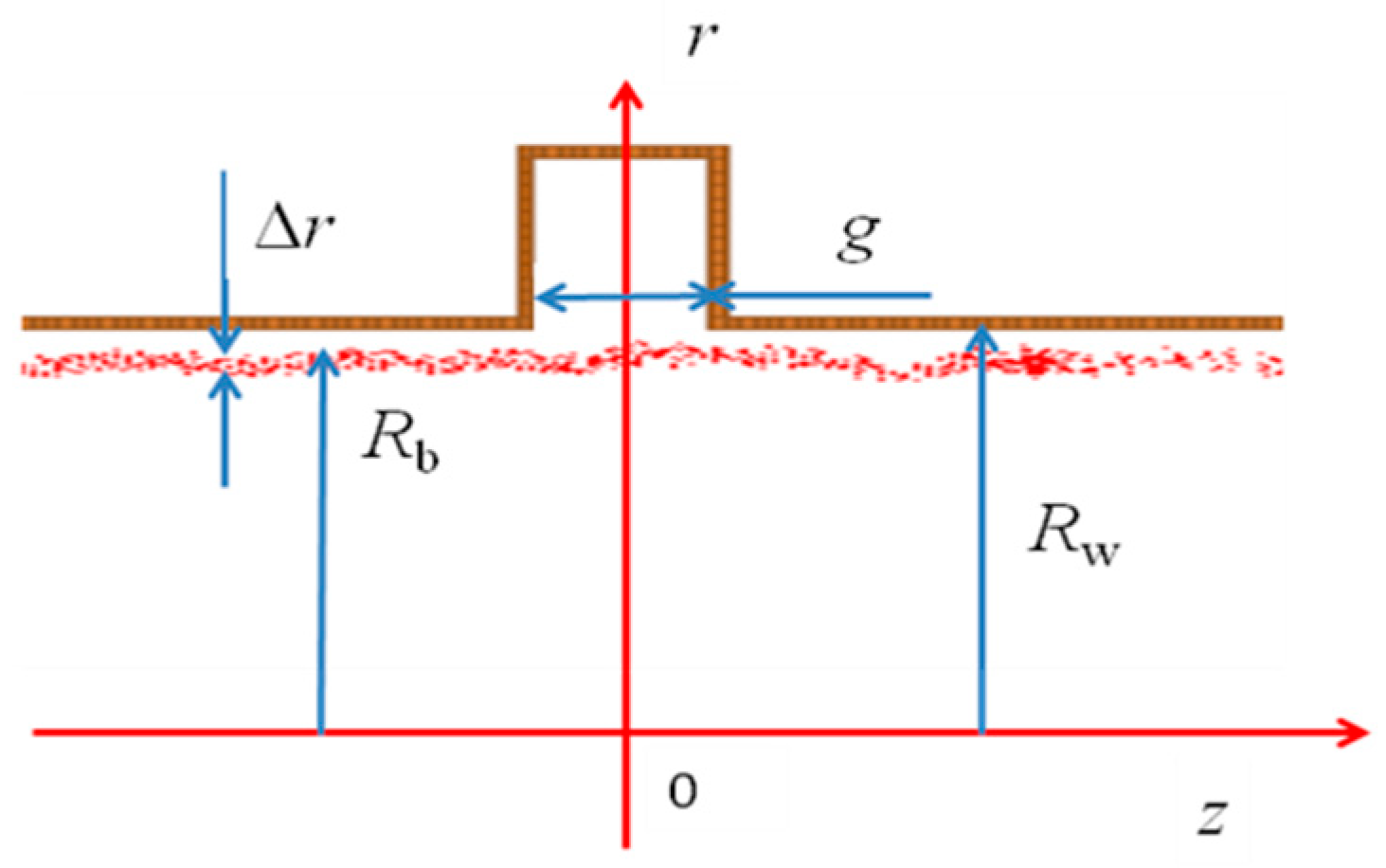
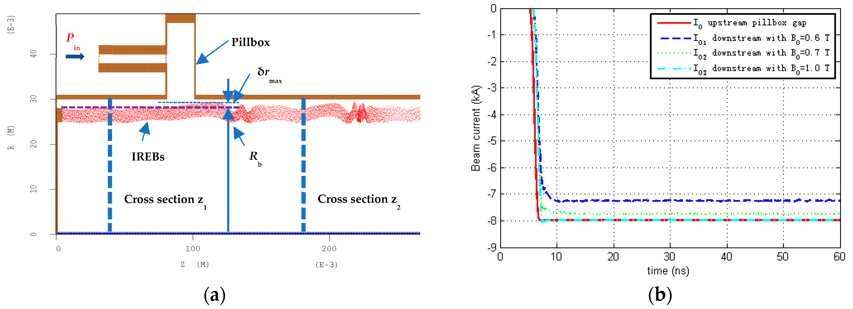
Our goal is to examine the radial motion of the electrons in the vicinity of a cavity, and in the presence of a guiding magnetic field ( B 0 ) —the geometric parameters of the cavity and the beam are revealed in Figure 2, which illustrates the output from CHIPIC [83].
In the gap of the cavity, we assume the existence of a uniform in space, steady-state ( exp j ω t ) in time-longitudinal electric fields of complex amplitude E ¯ 0 ; thus E z ( r = R w , | z | < g / 2 , t ) = Re [ E ¯ 0 exp ( j ω t ) ] . Explicitly, in the cylindrical waveguide ( r R w ) , the magnetic vector potential is:
A z ( r , z , ω ) = d k A ( k ) I 0 ( Γ r ) exp ( j k z )
wherein Γ 2 = k 2 ω 2 / c 2 ,   I 0 ( u ) is the zero-order-modified Bessel function of the first kind, and the amplitude A ( k ) is set by the field in the gap of the cavity ( r = R w ) :
E z ( z ) = d k c 2 Γ 2 j ω A ( k ) I 0 ( Γ R w ) exp ( j k z ) = { E ¯ 0 , | z | < g / 2 0 , otherwise
or explicitly:
A ( k , ω ) = E ¯ 0 j ω c 2 Γ 2 1 I 0 ( Γ R w ) 1 2 π g / 2 g / 2 d z exp ( j k z )
Thus, the field components in the entire volume ( r R w ,   | z | < ) of the waveguide are given by:
[ E z E r H ϕ ] = Re { E ¯ 0 exp ( j ω t ) g / 2 g / 2 d z 1 2 π d k [ I 0 ( Γ r ) ( j k / Γ ) I 1 ( Γ r ) ( j ω / c Γ η 0 ) I 1 ( Γ r ) ] exp [ j k ( z z ) ] I 0 ( Γ R w ) }
For completeness in the pillbox cavity ( R w < r < R ext ) , the dominant field components are:
E z ( r ) = E ¯ 0 [ J 0 ( ω c r ) Y 0 ( ω c R ext ) Y 0 ( ω c r ) J 0 ( ω c R ext ) ] H ϕ ( r ) = j η 0 E ¯ 0 [ J 1 ( ω c r ) Y 0 ( ω c R ext ) Y 1 ( ω c r ) J 0 ( ω c R ext ) ]
with η 0 = μ 0 / ε 0 representing the vacuum wave impedance, R ext is the external wall of the pillbox cavity, and J ν ( u ) ,   Y ν ( u ) ,   ν = 0 , 1 are the ν t h -order Bessel functions of the first and second kind, correspondingly.
Now that we have determined the rf field, we focus on the dc field, ignoring the metallic wall. Assuming a thin annular-beam carrying a current I with a velocity v z = c β , the effective electric field ( E r v z B ϕ ) at the beam location is:
E r ( S C ) ( r R b ) η 0 I β γ 2 1 2 π R b
and γ = 1 / 1 β 2 —note that these are average values. Here, we ignored the effects of the metallic wall on the static field components. With the dc and the rf components established, the radial equation of motion, ignoring the energy exchange due to the longitudinal oscillation, reads:
d d t v r 1 r v ϕ 2 = e m 1 γ ( E r ( R F ) + E r ( S C ) + v ϕ B 0 )   .
wherein e and m are the charge and rest mass of the electron, and:
E r , i ( R F ) ( t ) = [ E r v z B ϕ ] r = R b z = z i + c β t = Re { E ¯ 0 exp ( j ω t ) g / 2 g / 2 d z 1 2 π d k [ j k Γ β j ω c Γ ] I 1 ( Γ r ) exp [ j k ( z z ) ] I 0 ( Γ R w ) } r = R b z = z i + c β t
Due to the azimuthal symmetry of the problem, the canonical angular momentum is a constant of motion. Further, since the guiding magnetic field is uniform, the azimuthal component of the static magnetic vector potential is A ϕ = r B 0 / 2 ;   Ω c = e B 0 / m will represent in what follows, the non-relativistic cyclotron frequency. The conservation of the canonical angular momentum implies r p ϕ = r ( m γ v ϕ e A ϕ ) = r m ( γ v ϕ Ω c r / 2 )   =   const . , thus assuming that the ith electron has an initially zero azimuthal velocity:
v ϕ , i   = 1 2 r i γ i Ω c ( r i 2 r i , 0 2 )
and denoting by h ( u ) the Heaviside step function, we get:
d 2 r i d t 2 Ω c 2 4 r i 3 γ i 2 ( r i 2 r i , 0 2 ) 2 = e m 1 γ i E r , i ( R F ) + e m η 0 I β i γ i 3 h ( r i R b ) 2 π r i Ω c 2 2 r i γ i 2 ( r i 2 r i , 0 2 )
It should be emphasized that the effect of the image-charge, due to the wall presence, was tacitly neglected, since it is well-known that it tends to reduce the (effective) plasma frequency and in the framework of this analytic study, we consider only the main processes involved.
Next, we assess the equilibrium ( r eq R b ) in the absence of the rf, and we assume that the oscillation is small relative to the beam’s radius r i R b + δ r i ,   r i , 0 R b . Further defining the current and the plasma frequency I = e n c β ( 2 π R b ) Δ r ,   Ω p 2 = e 2 n / m ε 0 , the radial equation of motion for the ith electron is:
( γ i d 2 d t 2 + Ω c 2 γ i Ω p 2 γ i 2 ) δ r i e m E r , i ( R F )
Note that the dc space charge force (expressed in terms of the plasma frequency) is taken for the worst case scenario, namely all electrons are concentrated in an extremely thin layer, and the radial (image-charge) force between this layer and the waveguide’s wall is neglected. This can be readily corrected by replacing the plasma frequency with the effective plasma frequency, which accounts for the plasma frequency reduction, due to the ground metallic wall.

3. Effective Radial Force

Our goal in this section is to simplify the expression for the radial force F r ( t ) = e E r , i ( R F ) , and for this purpose, we employ the Cauchy residue theorem for the evaluation of the integral on k in Equation (8); thus:
G ( z , z ) 1 2 π d k I 1 [ R w k 2 ( ω / c ) 2 ] exp [ j k ( z z ) ] R w k 2 ( ω / c ) 2 I 0 [ R w k 2 ( ω / c ) 2 ] = 1 R w 2 s = 1 exp [ Γ s | z z | ] Γ s
wherein p s are the zeroes of the Bessel function of the first kind, J 0 ( p s ) = 0 , and Γ s ( p s / R w ) 2 ( ω / c ) 2 . With this definition, the radial force consists of an infinite manifold of evanescent waves, thus keeping in mind that from E ¯ 0 = E 0 exp ( j ψ ) , we get:
F r ( R F ) e E 0 = g R w s = 1 G s ( z ) J 1 ( p s r R w ) J 1 1 ( p s ) [ cos ( ω t + ψ ) + β ω c Γ s sin ( ω t + ψ ) ]
and here, G s ( z ) 1 g g / 2 g / 2 d z exp [ Γ s | z z | ] . At this stage, we consider the transverse kick experienced by the electron. In general, momentarily ignoring all of the force components except rf, the normalized transverse kick associated with the radial rfforce is given by:
m c d γ β r d t = F r ( R b , z = c β t , t ) Δ γ β r 1 m c d t F r ( R b , z = c β t , t )
or explicitly, in the framework of our model:
Δ γ β r e E 0 g / m c 2 = 1 g d t c g R w s = 1 G s ( c β t ) J 1 ( p s R b R w ) J 1 1 ( p s ) [ cos ( ω t + ψ ) + β ω c Γ s sin ( ω t + ψ ) ]
At r = R b the normalized transverse kick within an excellent approximation and for the specified parameters, is given by 1.293 cos ( ψ π / 6 ) . Now, we replace the exact rf force with the kick multiplied by the Delta function, such that the momentum transferred in the process is preserved, but its profile may differ quite significantly. Explicitly, the momentum transfer is given by:
d γ β r d t = Δ γ β r δ ( t )
or in our particular case, for the specified set of geometric parameters:
Δ γ β r = 1.293 e E 0 g m c 2 cos ( ψ π 6 )
and thus, after reinstating the other force components, we get:
( d 2 d t 2 + Ω c 2 γ i 2 Ω p 2 γ i 3 ) δ r i Δ γ β r c γ i δ ( t )
This equation may be readily solved, keeping in mind that the Green’s function of:
( d 2 d t 2 + Ω 2 ) G 0 ( t , t ) = δ ( t t )
is subject to the zero initial conditions: G 0 ( t = t , t ) = 0 , and [ d G 0 ( t , t ) / d t ] t = t = 0 is given by:
G o ( t , t ) = 1 Ω sin [ Ω ( t t ) ] h ( t t )
Thus:
δ r i ( t ) Δ γ β r c Ω c 2 Ω p 2 γ i 1 sin ( Ω c 2 γ i 2 Ω p 2 γ i 3 t ) h ( t )
This is the main analytical result of this study.

4. Discussion

Several features are evident from the present formulation:
  • For beam stability, it is required that the relativistic cyclotron frequency is significantly larger than the relativistic plasma frequency Ω c 2 γ 2 Ω p 2 γ 3 . In all of the expressions so far, we considered the average beam density, but we need to keep in mind that high-efficiency energy conversion is facilitated by a highly bunched beam; thus local density may exceed the averaged value by a factor of α = 10 or even higher. Consequently, it will be more realistic to adopt a more stringent constraint on the magnetic field Ω c 2 α   Ω p 2 γ 1 .
  • The radial transverse kick, Δ γ β r , is proportional to the amplitude of the radial oscillation.
  • In case of a quasi-periodic structure whereby electrons lose a significant fraction of their energy γ i ( z ) , the magnetic field is tapered Ω c ( z ) , the bunch density varies Ω p ( z ) , and assuming that there are no reflected electrons, then on the first order, we may assume that the radial oscillation as a function of the location is:
    δ r i ( z ) c Δ γ β r h ( z ) Ω c 2 ( z ) Ω p 2 ( z ) γ i 1 ( z ) sin ( 1 c 0 z d z Ω c 2 ( z ) Ω p 2 ( z ) γ i 1 ( z ) γ i 2 ( z ) 1 ) c Δ γ β r h ( z ) Ω c ( z ) sin ( 0 z d z Ω c ( z ) c γ i 2 ( z ) 1 )
  • According to the last result, there are several possibilities to taper the structure. Two are the most plausible: (i) Keeping the radius of the waveguide constant, but varying the guiding magnetic field and the external radius of the cavities (see in Figure 1b), such that the phase of the radial oscillation is preserved:
    Ω c ( z ) c γ i 2 ( z ) 1 = const .
    (ii) Varying the waveguide radius, and thus the volume of the constraint on the guiding field may be weakened:
    Ω c 2 ( z ) Ω p 2 ( z ) γ i ( z ) 1 γ i 2 ( z ) 1 = const .
See the bottom frame in Figure 1. However, the tapering in the latter case may be accompanied by a coupling to high-order modes (hybrid modes), which may lead to beam break-up.
In order to obtain a flavor regarding the maximum radial displacement, δ r max 1.293 ( e E 0 g / m c 2 ) ( c / Ω c ) 1.7 [ mm ] / B 0 [ T ] , that the electron beam is experiencing as it traverses the gap, we illustrate the following results of several particle in cell (PIC) simulations. The left frame of Figure 3 shows the configuration-space, and the latter reveals the radial oscillation very vividly. In the right frame, we show the beam transport over the cavity gap. The red curve shows the upstream current. Blue, green, and magenta represent the downstream currents for B 0 = 0.6 ,   0.7 ,   1.0 T . For the weaker magnetic field, the radial kick is larger; as a result, more electrons are intercepted by the structure, and thus, the transported current is lower.
In conclusion, we have developed an analytical approach that on one hand, may predict the radial oscillation near the aperture of a pillbox cavity, and on the other hand, it provides us with the natural criteria for the design of the tapered magnetic field in the output sections of a relativistic klystron amplifier, as well as the travelling wave tube.

Author Contributions

H.H. has initiated the collaboration. He and his group have designed the RKA and performed the numerical simulations. L.S. raised the question regarding the radial kick has developed the analytic model.

Funding

L.S. was supported by the Israel Science Foundation. H.H. was supported by the National Natural Science Foundation of China under Grant 11475158 and Grant 11605191.

Acknowledgments

L.S. wishes to thank the China Academy of Engineering Physics. H.H. thanks L.L.Li for his help with Figure 2 and Figure 3.

Conflicts of Interest

The authors declare no conflict of interest.

References

  1. Andrews, M.L.; Davitian, H.; Hammer, D.A.; Fleischmann, H.H.; Nation, J.A.; Rostoker, N. On the propagation of high-current beams of relativistic electrons in gases. Appl. Phys. Lett. 1970, 16, 98–100. [Google Scholar] [CrossRef]
  2. Nation, J.A. On the coupling of a high-current relativistic electron beam to a slow wave structure. Appl. Phys. Lett. 1970, 17, 491–494. [Google Scholar] [CrossRef]
  3. Nation, J.A. A simple technique for single shot, microwave spectrum analysis. Rev. Sci. Instrum. 1970, 41, 1097–1098. [Google Scholar] [CrossRef]
  4. Andrews, M.L.; Davitian, H.; Fleischmann, H.H.; Kusse, B.; Kribel, R.E.; Nation, J.A. Generation of Astron-Type E Layers Using Very High-Current Electron Beams. Phys. Rev. Lett. 1971, 27, 1428–1431. [Google Scholar] [CrossRef]
  5. Carmel, Y.; Nation, J.A. Application of intense relativistic electron beams to microwave generation. J. Appl. Phys. 1973, 44, 5268–5274. [Google Scholar] [CrossRef]
  6. Carmel, Y.; Nation, J.A. Microwave emission from an anisotropy instability in a high-current relativistic electron beam. Phys. Rev. Lett. 1973, 31, 806–808. [Google Scholar] [CrossRef]
  7. Carmel, Y.; Nation, J.A. Instability of an unneutralized relativistic electron beam. Phys. Rev. Lett. 1973, 31, 286–289. [Google Scholar] [CrossRef]
  8. Carmel, Y.; Ivers, J.; Kribel, R.E.; Nation, J. Intense coherent cherenkov radiation due to the interaction of a relativistic electron beam with a slow-wave structure. Phys. Rev. Lett. 1974, 33, 1278–1282. [Google Scholar] [CrossRef]
  9. Granatstein, V.L.; Herndon, M.; Sprangle, P.; Carmel, Y.; Nation, J.A. Gigawatt microwave from an intense relativistic electron beam. Plasma Phys. 1975, 17, 23–28. [Google Scholar] [CrossRef]
  10. Providakes, G.; Nation, J.A.; Read, M.E. Microwave Generation Using Sheet Relativistic Electron Beams. IEEE Trans. Microw. Theory Tech. 1977, 25, 563–566. [Google Scholar] [CrossRef]
  11. Gammel, G.; Nation, J.A.; Read, M.E. Technique for the measurement of the amplitude and phase velocity of a slow space charge wave on a relativistic electron beam. Rev. Sci. Instrum. 1978, 49, 507–509. [Google Scholar] [CrossRef] [PubMed]
  12. Gammel, G.; Nation, J.A.; Read, M.E. Slow space-charge wave propagation on a relativistic electron beam. J. Appl. Phys. 1979, 50, 5603–5608. [Google Scholar] [CrossRef]
  13. Providakes, G.; Nation, J.A. Excitation of the slow cyclotron and space-charge waves in a relativistic electron beam. J. Appl. Phys. 1979, 50, 3026–3030. [Google Scholar] [CrossRef]
  14. Ivers, J.D.; Nation, J.A. Compact 1-GW pulse power source. Rev. Sci. Instrum. 1983, 54, 1509–1510. [Google Scholar] [CrossRef]
  15. Greenwald, S.; Kerslick, G.; Nation, J.A. Space-charge wave growth and propagation on a relativistic electron beam. IEEE Trans. Nucl. Sci. 1985, 32, 3497–3499. [Google Scholar] [CrossRef]
  16. Anselmo, A.; Kerslick, G.; Nation, J.A.; Providakes, G. Space-charge wave propagation in inhomogeneous waveguides. Phys. Fluids 1985, 28, 358–365. [Google Scholar] [CrossRef]
  17. Anselmo, A.; Nation, J.A. Parametric growth of space charge waves using a self-biased electrostatic wiggler. Phys. Fluids 1988, 31, 2037. [Google Scholar] [CrossRef]
  18. Shiffler, D.; Nation, J.A.; Wharton, C.B. High-power traveling-wave tube amplifier. Appl. Phys. Lett. 1989, 54, 674–676. [Google Scholar] [CrossRef]
  19. Shiffler, D.; Nation, J.A.; Kerslick, G.S. A high-power, traveling wave tube amplifier. IEEE Trans. Plasma Sci. 1990, 18, 546–552. [Google Scholar] [CrossRef]
  20. Schachter, L.; Nation, J.A.; Kerslick, G. On the bandwidth of a short traveling wave tube. J. Appl. Phys. 1990, 68, 5874–5882. [Google Scholar] [CrossRef]
  21. Schachter, L.; Nation, J.A. Analysis of a traveling wave tube tuned by a cavity. J. Appl. Phys. 1991, 70, 5186–5192. [Google Scholar] [CrossRef]
  22. Shiffler, D.; Ivers, J.D.; Kerslick, G.S.; Nation, J.A.; Schachter, L. Sideband development in a high-power traveling-wave tube microwave amplifier. Appl. Phys. Lett. 1991, 58, 899–901. [Google Scholar] [CrossRef]
  23. Schächter, L.; Nation, J.A.; Shiffler, D.A. Theoretical studies of high-power Cerenkov amplifiers. J. Appl. Phys. 1991, 70, 114–124. [Google Scholar] [CrossRef]
  24. Shiffler, D.; Nation, J.A.; Schachter, L.; Ivers, J.D.; Kerslick, G.S. A high-power two stage traveling-wave tube amplifier. J. Appl. Phys. 1991, 70, 106–113. [Google Scholar] [CrossRef]
  25. Schächter, L.; Nation, J.A. Slow-wave amplifiers and oscillators: A unified study. Phys. Rev. A 1992, 45, 8820–8832. [Google Scholar] [CrossRef]
  26. Kuang, E.; Davis, T.J.; Kerslick, G.; Nation, J.A.; Schächter, L. Transit time isolation of a high power microwave amplifier. Phys. Rev. Lett. 1993, 71, 2666–2669. [Google Scholar] [CrossRef] [PubMed]
  27. Davis, T.J.; Schächter, L.; Nation, J.A. High power microwaves at 9 GHz from an extended length cavity in a coaxial beam geometry. Appl. Phys. Lett. 1993, 63, 1854–1856. [Google Scholar] [CrossRef]
  28. Schächter, L.; Nation, J.A. Analytical method for studying a quasiperiodic disk loaded waveguide. Appl. Phys. Lett. 1993, 63, 2441–2443. [Google Scholar] [CrossRef]
  29. Davis, T.J.; Schächter, L.; Nation, J.A. Results from an X-band coaxial extended length cavity. IEEE Trans. Plasma Sci. 1994, 22, 504–510. [Google Scholar] [CrossRef]
  30. Kuang, E.; Davis, T.J.; Ivers, J.D.; Kerslick, G.; Nation, J.A.; Schächter, L. Low group velocity traveling wave tube amplifiers. IEEE Trans. Plasma Sci. 1994, 22, 511–517. [Google Scholar] [CrossRef]
  31. Schächter, L.; Nation, J.A. On the coupling between a quasiperiodic structure and an asymmetric output arm. IEEE Trans. Microw. Theory Tech. 1995, 43, 42–47. [Google Scholar] [CrossRef]
  32. Schachter, L.; Nation, J.A.; Schächter, L.; Nation, J.A. Propagation of electromagnetic and space-charge waves in quasiperiodic structures. Phys. Plasmas 1995, 2, 889–901. [Google Scholar] [CrossRef]
  33. Naqvi, S.A.; Kerslick, G.S.; Nation, J.A.; Schachter, L. Axial extraction of high-power microwaves from relativistic traveling wave amplifiers. Appl. Phys. Lett. 1996, 69, 1550–1552. [Google Scholar] [CrossRef]
  34. Naqvi, S.A.; Kerslick, G.S.; Nation, J.A.; Schächter, L. Resonance shift in relativistic traveling wave amplifiers. Phys. Rev. E 1996, 53, 4229–4231. [Google Scholar] [CrossRef]
  35. Naqvi, S.A.; Nation, J.A.; Schächter, L.; Wang, Q. High-efficiency TWT design using traveling-wave bunch compression. IEEE Trans. Plasma Sci. 1998, 26, 840–845. [Google Scholar] [CrossRef]
  36. Schächter, L.; Nation, J.A. Beam-quality and guiding-magnetic-field requirements for a high-power traveling-wave amplifier operating at 35 GHz. Phys. Rev. E 1998, 57, 7176–7183. [Google Scholar] [CrossRef]
  37. Wang, P.; Xu, Z.; Ivers, J.D.; Nation, J.A.; Naqvi, S.; Schachter, L. Efficient operation of a high-power X-band traveling wave tube amplifier. Appl. Phys. Lett. 1999, 75, 2506–2507. [Google Scholar] [CrossRef]
  38. Banna, S.; Nation, J.A.; Schächter, L.; Wang, P. The interaction of symmetric and asymmetric modes in a high-power traveling-wave amplifier. IEEE Trans. Plasma Sci. 2000, 28, 798–811. [Google Scholar] [CrossRef]
  39. Wang, P.; Xu, Z.; Nation, J.A.; Banna, S.; Schachter, L. Symmetric and asymmetric mode interaction in high-power traveling wave amplifiers: Experiments and theory. IEEE Trans. Plasma Sci. 2000, 28, 2262–2271. [Google Scholar] [CrossRef]
  40. Banna, S.; Schachter, L.; Nation, J.A.; Wang, P. Coupling of symmetric and asymmetric modes in a high-power, high-efficiency traveling-wave amplifier. Phys. Rev. E 2000, 61, 4445–4449. [Google Scholar] [CrossRef]
  41. Schachter, L. Beam Wave Interaction in Periodic and Quasi-Periodic Structures, 2nd ed.; Springer: Heidleberg, Germany, 2011; ISBN 978-3-642-19848-9. [Google Scholar]
  42. Friedman, M. Another approach to the injection of relativistic electrons into an astronlike device. Phys. Rev. Lett. 1970, 25, 567–570. [Google Scholar] [CrossRef]
  43. Friedman, M. Passage of an Intense Relativistic Electron Beam through a Cusped Magnetic Field. Phys. Rev. Lett. 1970, 24, 1098–1100. [Google Scholar] [CrossRef]
  44. Friedman, M.; Ury, M. Production and focusing of a high power relativistic annular electron beam. Rev. Sci. Instrum. 1970, 41, 1334–1335. [Google Scholar] [CrossRef]
  45. Friedman, M. A new diode for the production of high power relativistic electron beams. Rev. Sci. Instrum. 1971, 42, 1255–1256. [Google Scholar] [CrossRef]
  46. Friedman, M.; Herndon, M. Emission of coherent microwave radiation from a relativistic electron beam propagating in a spatially modulated field. Phys. Rev. Lett. 1972, 29, 55–58. [Google Scholar] [CrossRef]
  47. Friedman, M.; Ury, M. Microsecond duration intense relativistic electron beams. Rev. Sci. Instrum. 1972, 43, 1659–1661. [Google Scholar] [CrossRef]
  48. Friedman, M.; Herndon, M. Microwave emission produced by the interaction of an intense relativistic electron beam with a spatially modulated magnetic field. Phys. Rev. Lett. 1972, 28, 210–213. [Google Scholar] [CrossRef]
  49. Friedman, M.; Hammer, D.A. Catastrophic disruption of the flow of a magnetically confined intense relativistic electron beam. Appl. Phys. Lett. 1972, 21, 174–177. [Google Scholar] [CrossRef]
  50. Friedman, M.; Sprangle, P. Conditions for the production of rotational annular beams of relativistic electrons using a cusped magnetic field. Plasma Phys. 1972, 14, 207–210. [Google Scholar] [CrossRef]
  51. Friedman, M.; Herndon, M. Generation of intense infrared radiation from an electron beam propagating through a rippled magnetic field. Appl. Phys. Lett. 1973, 22, 658–660. [Google Scholar] [CrossRef]
  52. Friedman, M.; Herndon, M. Emission of coherent microwave radiation from a relativistic electron beam propagating in a spatially modulated field. Phys. Fluids 1973, 16, 1982–1995. [Google Scholar] [CrossRef]
  53. Friedman, M.; Hammer, D.A.; Manheimer, W.M.; Sprangle, P. Enhanced microwave emission due to the transverse energy of a relativistic electron beam. Phys. Rev. Lett. 1973, 31, 752–755. [Google Scholar] [CrossRef]
  54. Friedman, M.; Vitkovitsky, I.M. Implosion of an unneutralized drifting relativistic electron beam. Appl. Phys. Lett. 1974, 25, 259–260. [Google Scholar] [CrossRef]
  55. Friedman, M. Formation of a virtual cathode by a relativistic electron beam flowing through a cavity. Appl. Phys. Lett. 1974, 24, 303–305. [Google Scholar] [CrossRef]
  56. Friedman, M. Emission of intense microwave radiation from an automodulated relativistic electron beam. Appl. Phys. Lett. 1975, 26, 366–368. [Google Scholar] [CrossRef]
  57. Friedman, M. Unstable Flow of a Magnetically Focused Unneutralized Relativistic Electron Beam. Phys. Rev. Lett. 1975, 35, 572–574. [Google Scholar] [CrossRef]
  58. Friedman, M.; Siambis, J.G.; Bacon, D.P. Conditions for the self-destruction of a pulsed intense relativistic electron beam. Appl. Phys. Lett. 1976, 28, 308–311. [Google Scholar] [CrossRef]
  59. Friedman, M.; Serlin, V. Conversion of the energy of intense relativistic electron beams into high-power electrical pulses. Rev. Sci. Instrum. 1983, 54, 1764–1766. [Google Scholar] [CrossRef]
  60. Friedman, M.; Serlin, V.; Drobot, A.; Seftor, L. Propagation of intense relativistic electron beams through drift tubes with perturbed walls. Phys. Rev. Lett. 1983, 50, 1922–1925. [Google Scholar] [CrossRef]
  61. Friedman, M.; Serlin, V.; Drobot, A.; Seftor, L. Self-modulation of an intense relativistic electron beam. J. Appl. Phys. 1984, 56, 2459–2474. [Google Scholar] [CrossRef]
  62. Friedman, M.; Serlin, V. Generation of a modulated intense relativistic electron beam with a frequency tunable by a magnetic field. Rev. Sci. Instrum. 1984, 55, 1074–1076. [Google Scholar] [CrossRef]
  63. Friedman, M.; Serlin, V. Interaction of a modulated intense relativistic electron beam with a cavity. Appl. Phys. Lett. 1984, 44, 394–395. [Google Scholar] [CrossRef]
  64. Friedman, M.; Serlin, V. Modulation of intense relativistic electron beams by an external microwave source. Phys. Rev. Lett. 1985, 55, 2860–2863. [Google Scholar] [CrossRef] [PubMed]
  65. Friedman, M.; Serlin, V. Parametric interaction of modulated intense relativistic electron beams with high-voltage gaps. Phys. Rev. Lett. 1985, 54, 2018–2021. [Google Scholar] [CrossRef] [PubMed]
  66. Friedman, M.; Serlin, V. Behavior of high-voltage gaps in the presence of large space-charge fields. J. Appl. Phys. 1985, 58, 1460–1465. [Google Scholar] [CrossRef]
  67. Friedman, M.; Serlin, V. Particle accelerators powered by modulated intense relativistic electron beams. Appl. Phys. Lett. 1986, 49, 596–598. [Google Scholar] [CrossRef]
  68. Friedman, M.; Serlin, V. Generation of a high-power rf pulse in a rectangular waveguide. Rev. Sci. Instrum. 1987, 58, 58–59. [Google Scholar] [CrossRef]
  69. Friedman, M.; Serlin, V. Electrostatic insulation of a high-voltage gap. IEEE Trans. Electr. Insul. 1988, 23, 51–56. [Google Scholar] [CrossRef]
  70. Lau, Y.Y.; Friedman, M.; Serlin, V.; Krall, J. Nonlinear Space-Charge Waves on an Intense Relativistic Electron Beam. IEEE Trans. Plasma Sci. 1988, 16, 249–257. [Google Scholar] [CrossRef]
  71. Friedman, M.; Krall, J.; Lau, Y.Y.; Serlin, V. Externally modulated intense relativistic electron beams. J. Appl. Phys. 1988, 64, 3353–3379. [Google Scholar] [CrossRef]
  72. Friedman, M.; Serlin, V.; Lau, Y.Y.; Krall, J. Electron accelerators driven by modulated intense relativistic electron beams. Phys. Rev. Lett. 1989, 63, 2468–2471. [Google Scholar] [CrossRef] [PubMed]
  73. Lau, Y.Y.; Friedman, M.; Krall, J.; Serlin, V. Relativistic Klystron amplifiers driven by modulated intense relativistic electron beams. IEEE Trans. Plasma Sci. 1990, 18, 553–569. [Google Scholar] [CrossRef]
  74. Krall, J.; Friedman, M.; Lau, Y.Y.; Serlin, V. Simulation Studies of a Klystronlike Amplifier Operating in the 10–100 GW Regime. IEEE Trans. Electromagn. Compat. 1992, 34, 222–228. [Google Scholar] [CrossRef]
  75. Friedman, M.; Fernsler, R.; Slinker, S.; Hubbard, R. Intense Relativistic Electron Beams into rf Waves. Phys. Rev. Lett. 1995, 75, 1214–1217. [Google Scholar] [CrossRef] [PubMed]
  76. Friedman, M.; Serlin, V.; Lampe, M.; Hubbard, R.; Colombant, D.; Slinker, S. Intense electron beam modulation by inductively loaded wide gaps for relativistic klystron amplifiers. Phys. Rev. Lett. 1995, 74, 322–325. [Google Scholar] [CrossRef] [PubMed]
  77. Friedman, M.; Serlin, V. Generation of a large diameter intense relativistic electron beam for the triaxial relativistic klystron amplifier. Rev. Sci. Instrum. 1995, 66, 3488–3493. [Google Scholar] [CrossRef]
  78. Friedman, M. Propagation of an intense relativistic electron beam in an annular channel. J. Appl. Phys. 1996, 80, 1263–1267. [Google Scholar] [CrossRef]
  79. Friedman, M.; Pasour, J.; Smithe, D. Modulating electron beams for an X band relativistic klystron amplifier. Appl. Phys. Lett. 1997, 71, 3724–3726. [Google Scholar] [CrossRef]
  80. Friedman, M.; Fernsler, R.F. Guiding radio frequency waves on metallic foils. Appl. Phys. Lett. 1999, 74, 3468–3470. [Google Scholar] [CrossRef]
  81. Friedman, M.; Swanekamp, S.; Obenschain, S.; Chan, Y.; Ludeking, L.; Smithe, D. Stability of large-area electron-beam diodes. Appl. Phys. Lett. 2000, 77, 1053–1055. [Google Scholar] [CrossRef]
  82. Friedman, M. Extraction of radio frequency from electromagnetic surface waves guided by metallic strips. Rev. Sci. Instrum. 2000, 71, 551–553. [Google Scholar] [CrossRef]
  83. Zhou, J.; Liu, D.; Liao, C.; Li, Z. CHIPIC: An Efficient Code for Electromagnetic PIC Modeling and Simulation. IEEE Trans. Plasma Sci. 2009, 37, 2002–2011. [Google Scholar] [CrossRef]
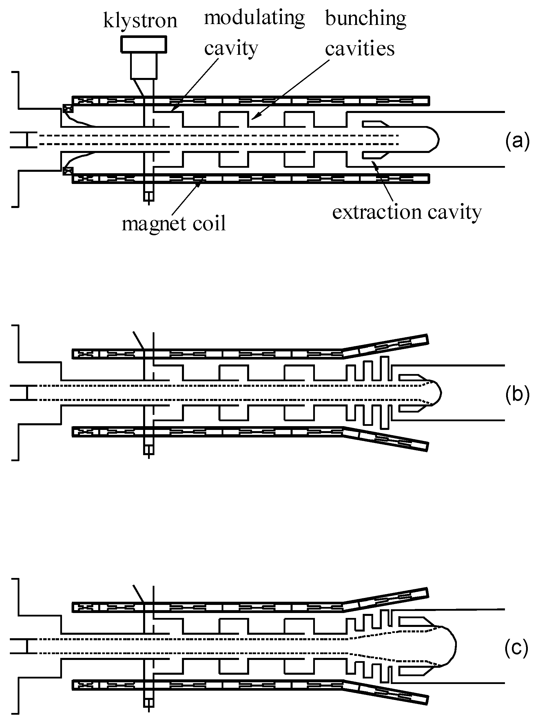
Figure 1. (a) Schematic description (not up to scale) of the relativistic klystron amplifier designed by one of us (HH). A single-output cavity is employed. (b) The radii of the drift tube and beam are kept uniform; the intensity of the guiding field is tapered. (c) Both the beam, the cavity, and the guiding field are varied.
Plasma 02 00003 g001
Figure 2. Schematic description (not up to scale) of a pillbox cavity attached to a waveguide. R w is the radius of the waveguide; R b is the annular-beam average radius, and Δ r represents its thickness; g is the gap. The system is assumed to be azimuthally symmetric. Not shown is the guiding magnetic field of intensity B 0 along the z-direction.
Plasma 02 00003 g002
Figure 3. Left frame: PIC simulation—see [83] for details—revealing the transverse kick exerted on the electrons by the rf field in the cavity. Right frame: Beam transport over the cavity gap. The red curve shows the upstream current. Blue, green, and magenta represent the downstream currents for B 0 = 0.6 ,   0.7 ,   1.0 T . For the weaker magnetic field the radial kick is larger, and as a result, more electrons are intercepted by the structure, and thus the transported current is lower.
Plasma 02 00003 g003