1. Introduction
Gyrotons are perspective devices of high-power microwave and plasma electronics. The principle of gyroton operation is presented in the following papers [
1,
2,
3,
4,
5,
6,
7,
8]. The spatial bunching of electrons does not occur in a gyroton. The initially rectilinear electron beam enters on the center of a revolving asymmetrical TM field, where its circular sweep and beam electron trajectories are congruent, i.e., electron trajectories repeat each other but with the phase shift. This is the fundamental difference between a gyroton and a gyrotron: where the transverse bunching of the spiral electron beam occurs in the usually symmetrical TE fields of a smooth waveguide.
The original idea of a device with revolving fields was proposed by I. Kaufman and G. Oltman in 1965 [
9]. This device was called “bermutron”. Later this idea was developed in [
10,
11], but the device was already named “gyrocon”. Then the basic constructions of devices with the revolving fields were proposed in [
1,
2,
3]. Later, one of the variants of this device was proposed in [
12,
5]. This device was called “magnicon” [
13,
14]. We use the name “gyroton” in this work since this name was already accepted in [
3].
Gyrocon and gyroton have distinct designs and mechanisms of electrons interaction with the field of electrodynamic structure. Indeed, gyrocon is the double-cavity amplifier, gyroton—the single-cavity generator. The electron-phasing processes and energy exchange with the electromagnetic field in a gyroton are combined in the single resonator, while these processes are separated and occur in different assemblies in a gyrocon: the beam modulation takes place in the input resonator, the circular sweep—in the space between the first and the second resonators and the extraction of energy—in the gap of the output ring resonator. The energy extraction in a gyrocon occurs in the narrow cavity gap with the small angle of electrons transit; in a gyroton, inside the cavity on gyroresonance condition. This makes the gyroton a much more promising device in the high-frequency range in comparison with the gyrocon.
The proposed gyroton-generator scheme is shown in
Figure 1. The dominant role in operation mechanism of such device plays the TM
11 wave which is strongly coupled with the TE
11 wave in the corrugated waveguide. The waveguide corrugation leads to the slowdown of the phase velocity along the waveguide. This makes it possible to substantially decrease the required magnetostatic field value to achieve the synchronism between the electron beam and the traveling slow wave.
A case where the output waveguide is regular was examined in [
3]. The development of effective generation process in this modification is possible only in the presence in the system of the magnetostatic field rising to the synchronous value when the regime of the gyroresonance occurs. This leads to strong dependency of generation efficiency on the beam thickness. There is no such dependence in the proposed gyroton, therefore it is possible to reach high efficiencies also for the relatively thick high-power electron beams.
Previously proposed traveling wave gyroton [
4] is based on the anomalous Doppler effect [
6,
15]. The calculated TM
11 wave phase velocity is less than the longitudinal velocity of electrons, and the following equation is satisfied
here
—longitudinal velocity of electrons,
—TM
11 wave phase velocity,
—relativistic cyclotron frequency. Electrodynamic calculation of phase velocity for one corrugation crest for TM
11 wave yields the following result in the considered case
and the longitudinal electrons velocity is
. The traveling wave gyroton is one of the possible realizations of the maser creation idea based on the anomalous Doppler effect with revolving fields.
In the gyroton with a corrugated resonator, the partial TM
11 wave phase velocity (
) is greater than the longitudinal electrons velocity. There is a coupled resonator-chain in such gyroton, where the TM
11 wave resonates, and the coupling is achieved through the TE
11 wave. Therefore, in this case we do not deal with the anomalous Doppler effect. Synchronous regime here is determined by the following condition:
This equation follows from the equality of the wave phase change and the electron phase change:
In traditional gyrotrons the relativistic cyclotron frequency must be approximated to the operating frequency [
6,
16,
17,
18]. So, the gyrotrons advance into range of higher frequencies is limited by the strong magnetostatic fields creation possibility. As it follows from the Equations (1) and (2), gyrotons can operate at higher frequencies than gyrotrons for the same magnetostatic fields values.
In the corrugated resonator the operating region is sufficiently extended to about 4 wavelengths, while in the cascade gyroton [
3] impact interaction occurs. The corrugated resonator usage makes possible to reduce substantially electric field strength in it.
In References [
2,
10] only the regime with traveling waves with bimodal approximation is examined. Here, we investigate the standing wave operation regime, taking into account a set of evanescent wave modes. In the corrugated resonator, two traveling towards to each other slow TM
11 waves are present, but the wave traveling together with the beam performs the dominant role. In the output waveguide only one TE
11 wave propagates and other waves are evanescent. However, the TM
11 wave has a primary role in the resonator.
The
Figure 2 represents schematically the electron motion in the wave TM
11 rotating with the frequency ω in the presence of longitudinal magnetostatic field
Hz0. Rectilinear electron beam in the waveguide center moves from the
z-axis under the action of the TM
11 wave magnetic field
Ht and it gains transverse velocity
Vt. Then electrons start to revolve along the Larmor orbit and fall into the TM
11 wave phase. As a result,
Ez field of the wave extracts energy from electrons.
2. Mathematical Model
The mathematical model of the processes occurring in the gyroton consists of two parts:
- -
the electromagnetic waves excitation equations in the axisymmetric longitudinally irregular waveguide by a relativistic electron beam;
- -
the electron beam motion equations in the excited electromagnetic fields.
The irregular waveguide excitation equations were built on the basis of the coordinates transformation method [
5,
19]. It consists in the substitution of the excitation problem of an irregular waveguide by the excitation of a regular waveguide with the waveguide radius equal to one. This is achieved by the coordinate system replacement. The new coordinate system (
ρ,
φ,
s) is introduced instead of usual polar coordinates (
r,
φ,
z), using the following equations:
where
b is the internal radius of the waveguide. The contravariant directional vectors system in this case takes the following form:
Maxwell’s equations in the new coordinates (
ρ,
φ,
s) in the covariant form are written as follows:
The metric tensor into Equation (6) takes the following form:
where
,
,
.
Now, expression for the internal waveguide surface in the coordinate system (
ρ,
φ,
s) will take the following form:
The boundary conditions of the waveguide surface in the new coordinate system take the following form:
The performed coordinates transformation makes possible to try the wave equations solution in the form of expansions in terms of the regular cylindrical waveguide basic functions. For example, it is possible to search the equations solution (6) for the electrical and magnetic field strengths in the form:
where
and the eigenmodes of a regular waveguide are defined as
Here m is the fundamental frequency ω harmonic number, n is the phase index, i is the radial index, j is the imaginary value, νni are the Bessel function roots (Jn(νni) = 0), and μni are the Bessel function derivative roots (J’n(μni) = 0).
The physical vectors
E,
H,
J are defined via the calculated ones as
The Galerkin method was used for solving Maxwell’s equations [
5,
20]. This method is also called “the method of orthogonalization” and it consists in the fact that the coefficients of expansions (11) are determined from the equations residuals orthogonality condition Equation (6) to the expansion eigenvectors Equation (12) with any
s:
The expansion coefficients Equation (11) are determined from the Equation (14) by the following ordinary differential equations system:
Here the following designations are accepted:
The equations system Equation (15) is the longitudinally irregular waveguide excitation by external sources problem solution. In this system, the E and H wave modes with the identical azimuthal indices n are coupled that is caused by the azimuthal waveguide symmetry.
Considering Equations (8), (14) and (15), it is possible to write down the physical vectors of the electromagnetic fields in the following form:
Here .
The motion equations of the
i-th charged particle in the irregular waveguide electromagnetic field in the heterogeneous magnetostatic field take the form:
Here the following designations are accepted:
Initial conditions for the system of Equations (15) in the electron beam initial modulation absence can be defined in the following form:
where
N—the electrons number,
—normalized initial electrons velocity,
,
rvc—normalized radius of the electrons Larmor orbit center,
—ratio of the electrons transverse velocity to the longitudinal velocity.
The electronic efficiency is defined as
3. Algorithm and Calculations Results
The method proposed in this article reduces the 3D task to 1D. It increases considerably both speed and accuracy of boundary-value problem solution. The known codes MAGIC [
21], CST [
22], KARAT [
23], and MAGY [
24] etc. do not have such convergence speed of boundary-value problems solution, and this makes it impossible to solve the optimization problem of the gyroton waveguide profile in the acceptable calculating time.
The Cauchy problem direct solution for the electrons motion equations system and waves excitation in an irregular waveguide by the usual integration methods (for example, the Runge-Kutta method) is impossible when evanescent modes are taken into account. The equations system is very unstable in this case. The method of block matrix dispersion was used to solve the boundary-value problem [
25].
Own software package CEDR (complex of electrodynamic resolutions) [
26], that was developed for mathematical simulation and optimization of the nonlinear and linear processes of relativistic electron beam interaction with the irregular electrodynamic systems fields, has been used in our work for the calculations in spectral domain, i.e., we have investigated the steady-state regime. We have applied the module GYRO-K of the package CEDR. The self-consistent nonlinear problem has been solved. The starting current has been determined asymptotically by decreasing current from the working value to the value when efficiency of the device was close to zero. We have determined the amplitude characteristic at the same time. The analysis of it indicates stability of the generation excitation process in the device. The detailed investigations that were conducted in the work [
27] confirm the generation process stability in a gyroton.
The search for the gyroton optimal construction with corrugated resonator with the help of the described program has yielded the following result: accelerating voltage V0 = 381 kV, beam current I0 = 8.7 A, resonator length l = 2πL/λ0 = 25, corrugation internal radius g1 = 2πr1/λ0 = 2.902, corrugation amplitude Δg = 2πΔr/λ0 = 2.05, the output ridge radius g3 = 1.902, the corrugation edges number n = 14, the magnetostatic field value F = H/Hs = 1.113.
Only one TE11 wave propagates in the output waveguide. The corrugation cavities form five coupled double-humped resonators operating mostly on TM11 wave. In total, 16 wave modes were considered in the calculations: eight waves TM11–TM18 and eight waves TE11–TE18. The obtained results were verified by increasing the calculations accuracy: the waveguide base functions number was varied from 16 to 64 and the integration steps number—from 2000 to 8000. The accuracy change did not exceed 1% in this case.
As it follows from
Figure 3, the largest amplitude has TM
11 wave. The electronic efficiency of this gyroton reaches 78%. The resonator profile is corrugated, and it is connected at the left side with the drift tube that is below-cutoff for all the wave modes (at the operating frequency); the rectilinear electron beam is injected through this tube center. To the right, the corrugation ends with the internal contraction, which increases the quality of this resonator.
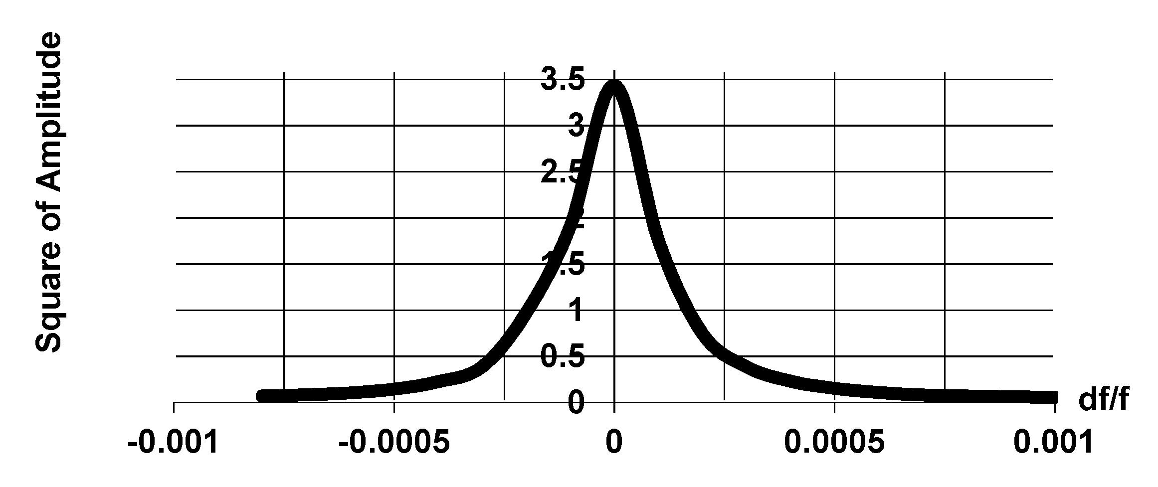
The frequency characteristics of the squared amplitude of the overall waves for the main resonance in this resonator at a constant power of the wave TM
11 falling to the right is presented in
Figure 4.
Figure 4 shows that the resonator cold
Q-factor is
Qn = 5250. Therefore, the field in this construction of gyroton can be considered as fixed with a high degree of accuracy.
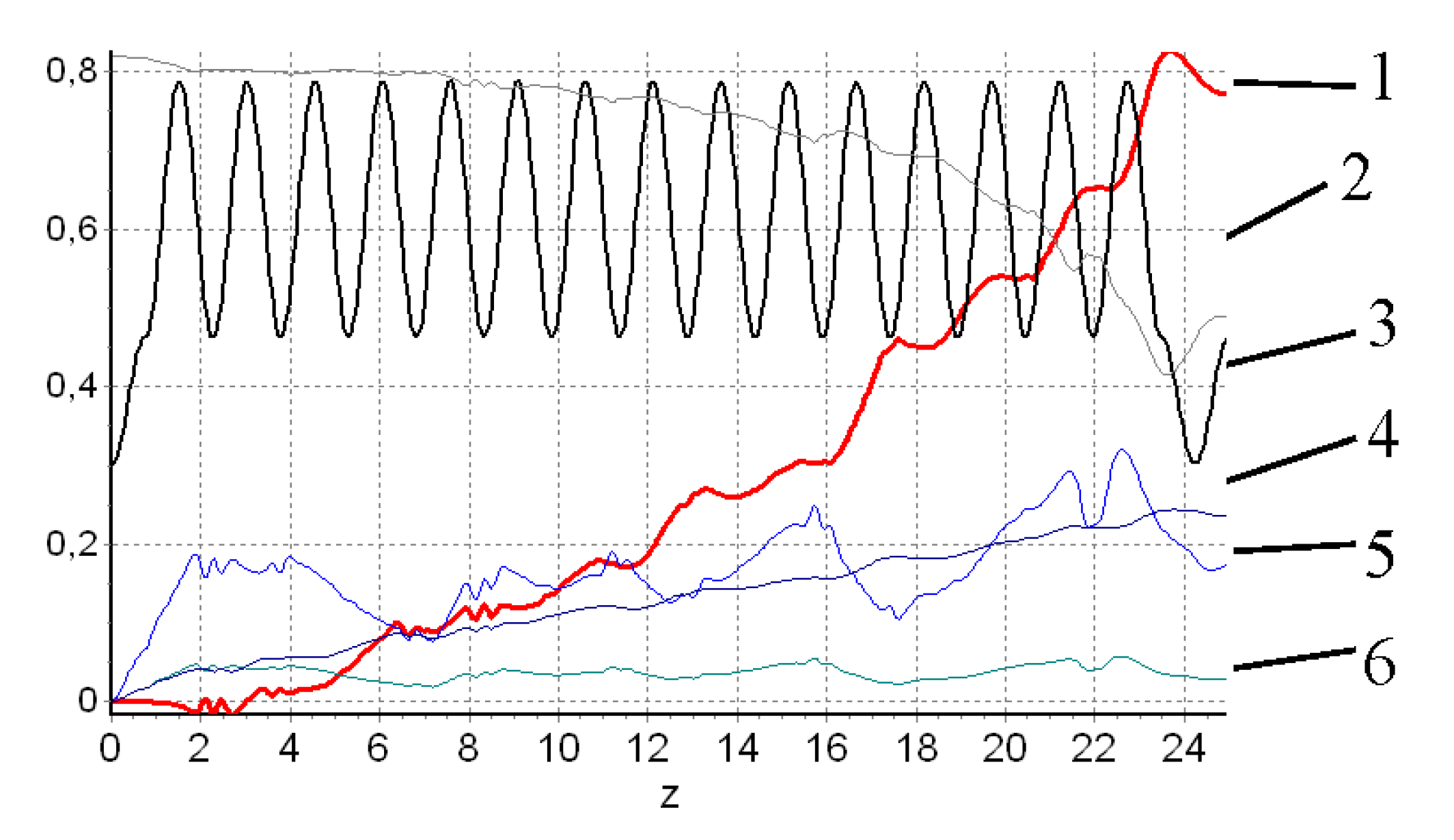
Figure 5 demonstrates the gyroton integral characteristics. One can see that the electron beam deviates initially from the axis by the transverse component of the rotating TM
11 wave high-frequency magnetic field. The electrons gyration radius and the rotation leading center radius increase simultaneously in this case (curves 4 and 6), this means that the electrons orbits only touch upon the resonator axis. Consequently, beginning with
z > 3, the electron beam begins to give up its longitudinal energy to the longitudinal electrical component of the TM
11 wave (curve 2). The efficiency increases almost monotonically with the growth of
z (curve 1), and the electron’s rotation center radial coordinate gradually moves away from the device axis (curve 4). So, device high efficiency is achieved only due to use of the electrons longitudinal energy.
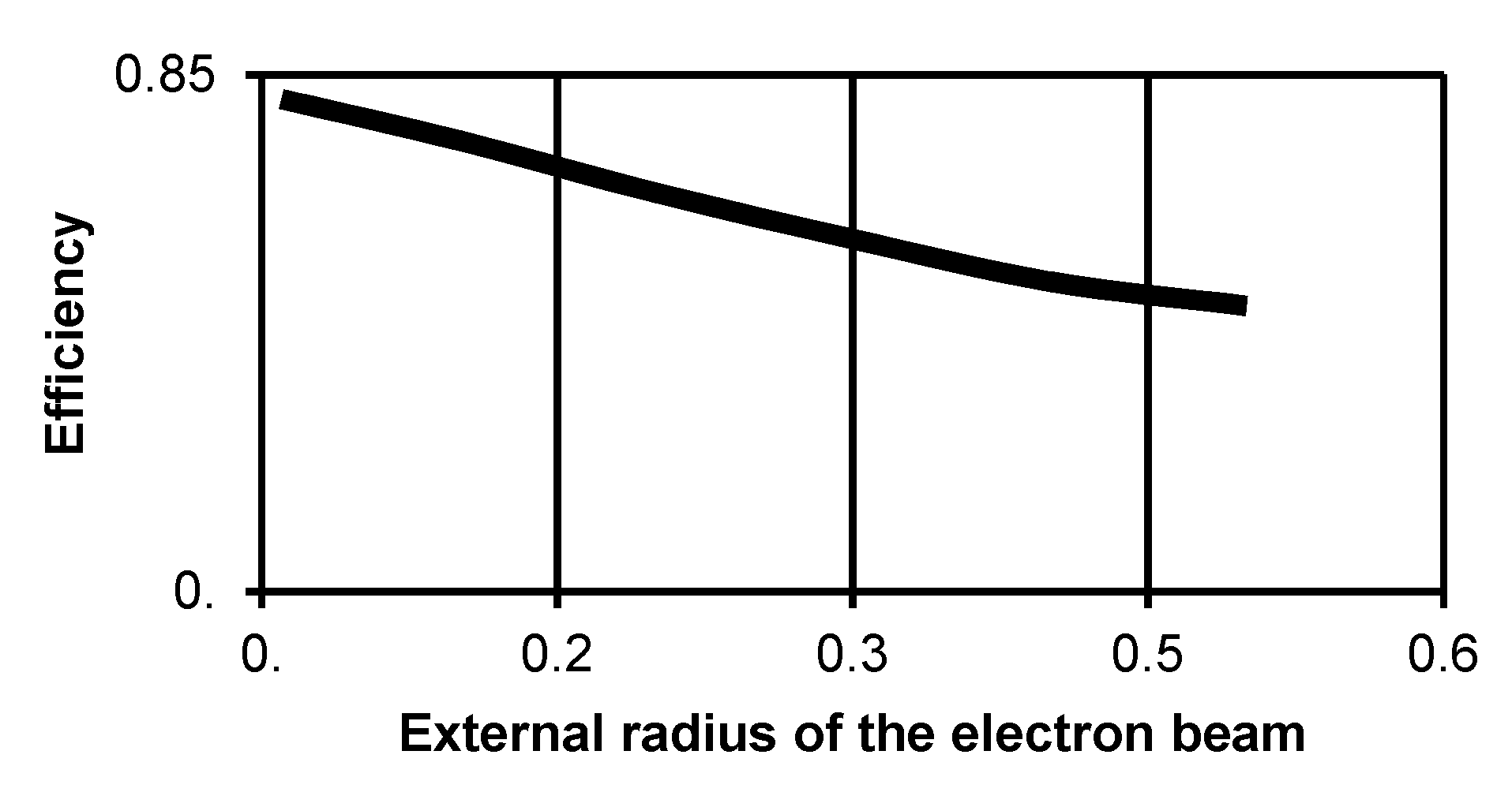
The internal ridge at the end of the resonator increases the resonator Q-factor up to 5250, which makes it possible to reduce the device operating current to 8.7 A. The linear estimation of the start-oscillation current is 6.7 A. However, it also limits the thickness of the electron beam to 2π
D/
λ ≤ 1. At the higher thicknesses the beam begins to deposit on this ridge. The reduction in the efficiency with the increase of the beam radius is shown in
Figure 6.
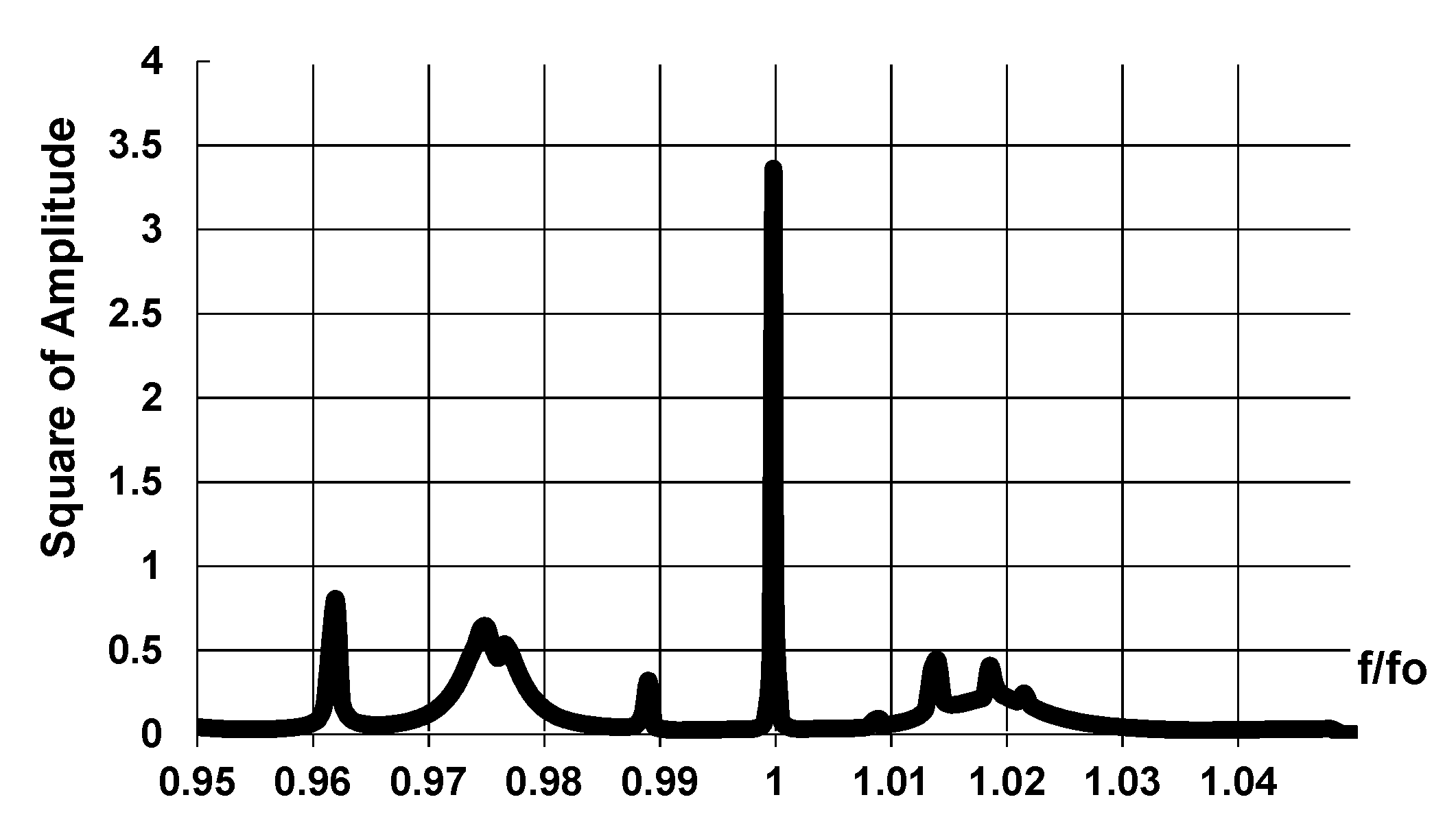
The resonator frequency characteristics study in a broad band (~10%) has been carried out. The frequency characteristic for the squared amplitude of the overall waves in the resonator in 10%-band of frequencies is presented in
Figure 7. Several resonances can be seen at the frequencies both lower and higher relative to the main resonance frequency.
As follows from
Figure 7, all existing resonances except for the main one possess lower diffraction quality and they cannot influence to the electron beam in the same manner as the main resonance.

 ,
, 