1. Introduction
Edge preparation of cutting tools, particularly through abrasive brushing, is a well-established process in modern manufacturing. Following primary shaping processes, cutting edges are typically sharp, which leads to high local stress concentrations during cutting operations. This condition makes the cutting edge prone to premature wear, micro-chipping, and unstable performance. Appropriate edge preparation can effectively suppress these defects, stabilize the cutting zone, and improve performance in demanding machining operations [
1]. In addition, edge preparation enhances coating adhesion and reduces crack initiation at the coating-substrate interface, thereby improving the durability of coated tools [
2]. Various methods have been developed for edge preparation, including mechanical, chemical, and thermal techniques. Brushing tools consist of polymer-based filaments embedded with abrasive particles. These filaments deform under load and adapt to complex workpiece geometries, enabling uniform treatment of curved or hard-to-access regions [
3]. Depending on the brushing kinematics, the edge form, size, and symmetry can be precisely influenced.
While considerable progress has been made in cutting edge preparation for conventional materials, the specific application of abrasive brushing tools on ceramic cutting tools remains insufficiently explored. Ceramics, known for their hardness and brittleness, present unique challenges for controlled edge rounding without introducing surface damage or compromising edge geometry and integrity. Uhlmann and Hoyer [
4,
5,
6] analyzed the deliberate surface treatment of ceramics, specifically Mg-ZrO
2, using abrasive brushing tools with bonded poly-crystalline diamond (PCD). They concluded that workpiece geometry is more difficult to control compared to metal surface finishing. In particular, new topographies were created at high brushing velocities v
b, whereas the brushing of metal surfaces typically only removes the roughness peaks but not the valleys. Hence, the controlled rounding of ceramic edges can be expected to be more challenging than for conventional materials [
7,
8]. Moreover, achieving a stable and consistently rounded cutting edge with low geometric variance remains a significant manufacturing challenge [
9].
Furthermore, this study aims to conduct foundational research regarding a robot-assisted edge rounding system using abrasive brushing tools. Robotic systems offer enhanced flexibility and repeatability as well as the potential for path-optimized brushing strategies, which are especially relevant for complex or variable workpiece geometries. However, there remains a gap in the literature concerning optimal brushing trajectories and their influence on the final edge form, particularly for ceramic tools, which usually require higher precision than industrial robots are capable of [
10]. Magnetic abrasive tools have been studied for edge preparation of hard metal tools, but show limitations in uniformity and accessibility [
11]. Such an extensive investigation could unfortunately not be conducted with zirconia-toughened alumina (ZTA) cutting tools. This work therefore addresses the development of adaptable, precision-oriented edge preparation strategies in automated manufacturing environments.
2. Materials and Methods
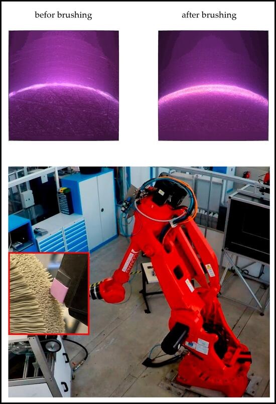
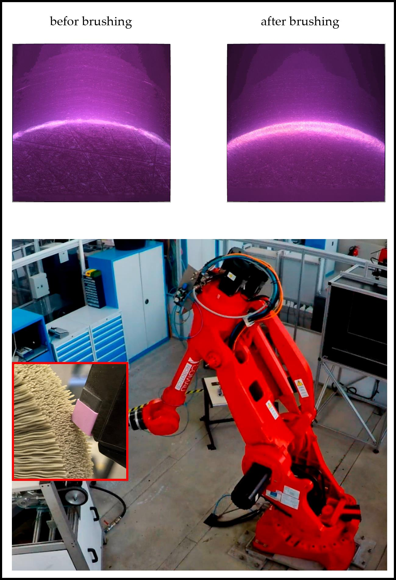
In this study, ZTA cutting inserts were used to investigate the effects of brushing-based edge preparation. The cutting insert material AKT 180 by CeramTec GmbH, Plochingen, Germany, is widely used in industry; however, detailed material properties are not disclosed by the manufacturer. Nevertheless, based on the information provided, the ceramic grade can be identified from commercially available sources. An industrial robot of the type Smart NJ 370-2.7 by Comau S.p.A, Grugliasco, Italy, with a repeatability of Rp = ±0.1 mm was employed to handle the ceramic inserts during the brushing operations. Compared to the deviations in filament length lf and run-out error of the brushing tool resulting from tool manufacturing, the precision of the robot is a less decisive factor. The robot allowed for programmable adjustments of contact angle φ, axial feed rate vfa, infeed ae, and brushing velocity vb, ensuring repeatable and uniform interactions between the brushing tool and the cutting edge.
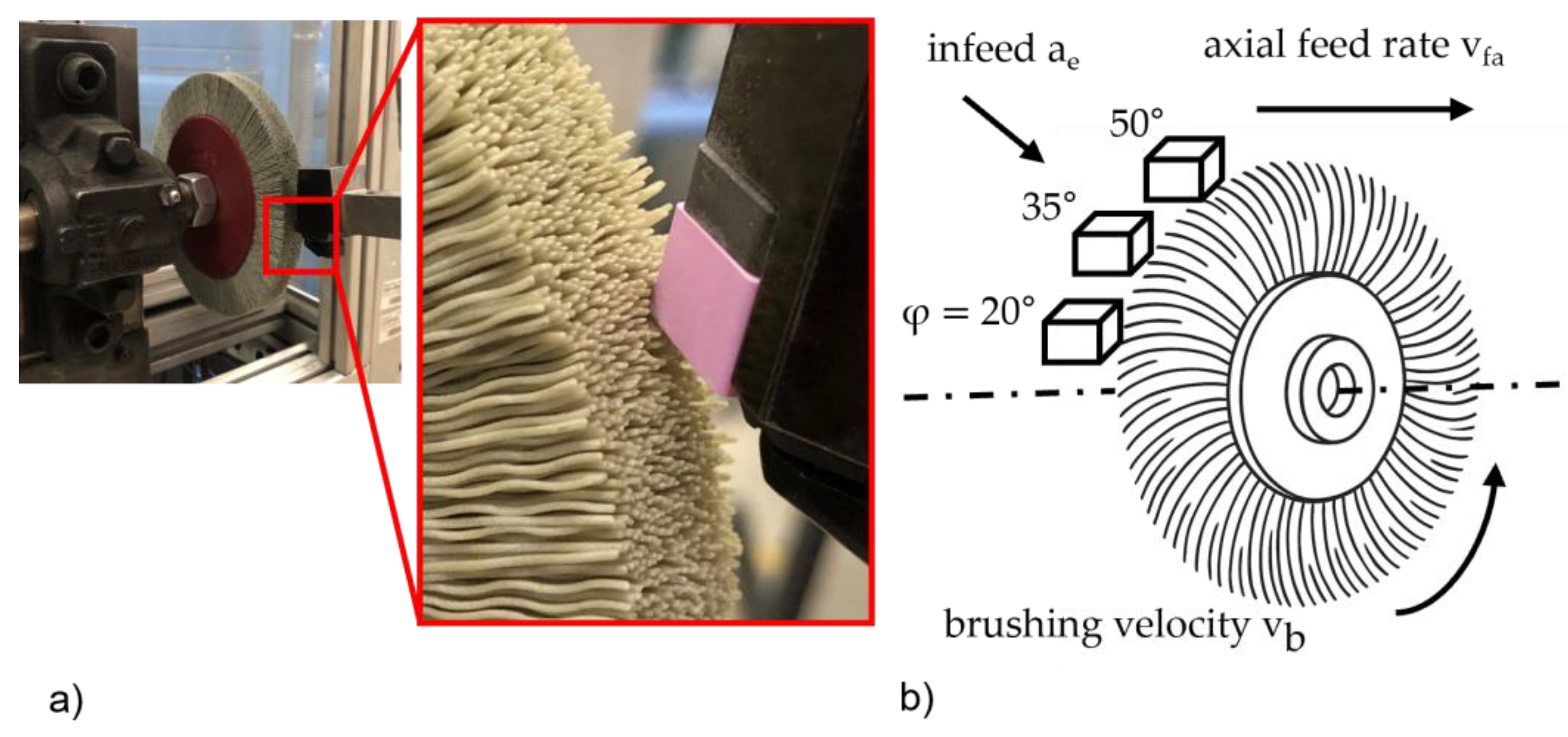
As shown in
Figure 1a, a lathe toolholder was used to mount the ceramic inserts, each of which contained eight cutting edges. This setup provided both firm fixation and protection for the edges not currently undergoing brushing. Particular attention was given to the orientation of the cutting edge relative to the brush, with the tool angle constrained between φ = 20 to 50° to ensure brushing tool engagement without damaging the toolholder. To allow uniform filament contact and utilize the entire brushing tool width, the cutting insert was moved linearly in axial direction with a constant axial feed rate v
fa. During the tests, both the infeed a
e and the axial feed rate v
fa were varied to study their effects on edge rounding and process stability.
Various round brushes by Carl Hilzinger-Thum GmbH & Co. KG, Tuttlingen, Germany, were examined, differing in filament diameter df, abrasive grit size sg, and filament length lf, although all tools shared an outer diameter of db = 150 mm. In the experimental section, it was stated that filaments with a diameter of df = 0.25 mm exhibited insufficient structural rigidity, while filaments with a diameter of df = 1.0 mm were excessively aggressive. To justify the selection of a filament diameter of df = 0.6 mm, preliminary brushing experiments were conducted. Filaments with a diameter of df = 0.25 mm were unable to produce effective edge rounding, even when very small targed edge radius rβ were specified. Moreover, no measurable increase in edge radius rβ was observed, despite applying aggressive process parameters that proved effective for other brushing tools. Instead of controlled material removal at the cutting edge, pronounced filament wear was observed. At brushing velocities as low as vb = 10 m/s, significant fine particle emission into the surrounding air and clogging of the tool holder occurred, indicating inefficiency and unstable process conditions. In contrast, filaments with a diameter of df = 1.0 mm exhibited high bending stiffness, leading to excessive localized material removal and clearly visible edge damage, which could be detected by visual inspection. A filament diameter of df = 0.6 mm provided a balanced combination of flexibility and stiffness, enabling stable, reproducible edge rounding without observable chipping, excessive wear, or process instability. Consequently, this filament diameter was selected for all subsequent experiments.
The contact angle φ was adjusted by modifying the relative position between the robot and the cutting insert, while maintaining a constant orientation of the cutting edge throughout the process,
Figure 1b.
Based on these observations, the brushing tool specification selected for the main experiments featured filaments with a diameter of df = 0.6 mm, a grit size of sg = 320 mesh, and a filament length of lf = 25 mm. Because the brush was newly manufactured and had not yet been conditioned for consistent performance, preliminary wear was created by repeatedly brushing the surface of a plain Al2O3 workpiece. This happened at a brushing velocity of vb = 20 m/s, a tangential feed rate of vft = 200 mm/min, an infeed of ae = 1 mm, and a total of Nb = 80 brushing cycles over a path length of lp = 100 mm. At the beginning of the process, the brushing tool caused a rapid reduction in surface roughness, followed by a continued but progressively slower decrease with increasing brushing cycles, but from approximately Nb = 20 cycles onward, the reduction in surface roughness per brushing cycle changed to less than 5% between successive cycles, indicating that the brushing tool had reached a quasi-steady wear condition. Therefore, all experiments were conducted within the range of Nb = 20 to 80 cycles to ensure stable brushing behavior. From around Nb = 20 to 80 cycles, the brushing tool exhibited stable performance, suggesting it had reached a steady-state wear condition. To ensure uniform filament wear, the brushing direction was reversed regularly through the test, allowing both sides of the filaments to participate in material removal.
To better understand the edge rounding geometry, Python 3.10 was used to post-process the measurement data obtained from the optical 3D surface profiler, an Alicona Infinite Focus SL by Bruker Austria GmbH, Graz, Austria. Key geometric features of the cutting edge were evaluated before and after brushing, such as edge radius rβ, form factor K, and shape deviation. A software tool for the cutting edge analysis was developed at the Institute of Machine Tools and Factory Management at Technische Universität Berlin. The tool, called Cutting Edge Characteristic (CEC), provides a more detailed characterization of the cutting edge than the conventional edge radius rβ. In this work, it is used to evaluate the quality of the rounded cutting edge.
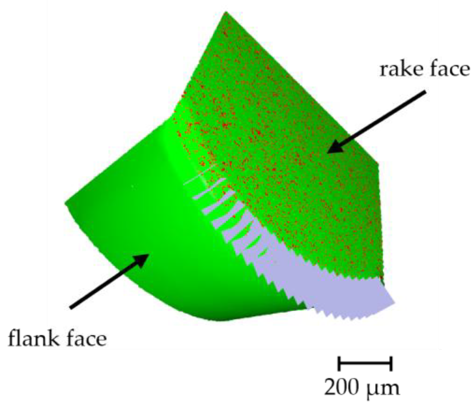
In the Python script, the rake face was reliably identified based on its planar characteristics, enabling robust surface fitting and clear separation from the flank face. As a result, the rake face is highlighted by red points in
Figure 2, which shows the segmentation result from the Python script. Using a neighborhood search algorithm, the adjacent flank surface was estimated by identifying local surface normals that are approximately perpendicular to the rake face. The projection of this flank surface was then used to calculate the gradient of the edge line. Based on this information, it was possible to define a series of section planes along the entire cutting edge at equidistant intervals. This enabled the extraction and evaluation of edge profiles from multiple positions across the full tool edge, providing a comprehensive geometric characterization.
Figure 2 illustrates the defined section planes along the cutting edge, indicating the locations where the 2D profile data were extracted from the 3D point cloud.
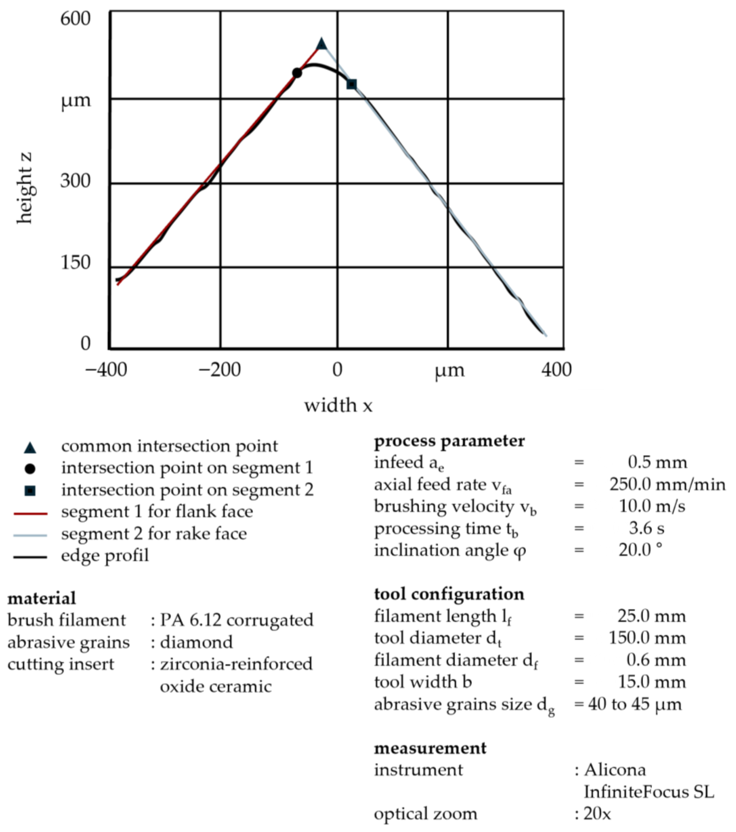
Figure 3 presents the 2D data extracted from a section of the 3D dataset. To analyze edge radius r
β and form factor K, the first step involved identifying two-line structures representing the rake and flank surfaces, extracted directly from the original 3D point cloud. Once these surfaces were fitted, a series of section points were calculated by intersecting the dataset with planes oriented along the cutting edge. These section points formed the basis for profile shift Δr, form factor K and rounding radius r
β. The intersection points between the regressed lines and the 3D dataset were used to define the precise locations on the rake and flank surfaces. For each surface, the nearest data point to the ideal intersection line was selected as the representative section point.
The edge radius r
β is defined as the radius of the circle that best approximates the measured cutting edge profile in the transition region between the rake and flank faces. The profile shift Δr represents the distance between the virtual intersection point of the extrapolated rake and flank face lines and the nearest point on the measured cutting edge profile. The form factor K is defined as the ratio of the virtual distances from the intersection point of the extrapolated rake and flank face lines to the measured edge profile on the rake face and the flank face, respectively. It therefore describes the asymmetry of the cutting edge rounding with respect to the rake and flank faces [
11,
12].
While the edge radius r
β and form factor K provide a general description of the cutting edge geometry, they are limited in their ability to capture local variations and details. The edge profile can be synthesized from multiple circular arcs or approximated using a polygonal representation. To achieve a more detailed characterization, the edge geometry was converted into a CEC-format representation, which describes the profile based on discrete resolved points along the edge [
13,
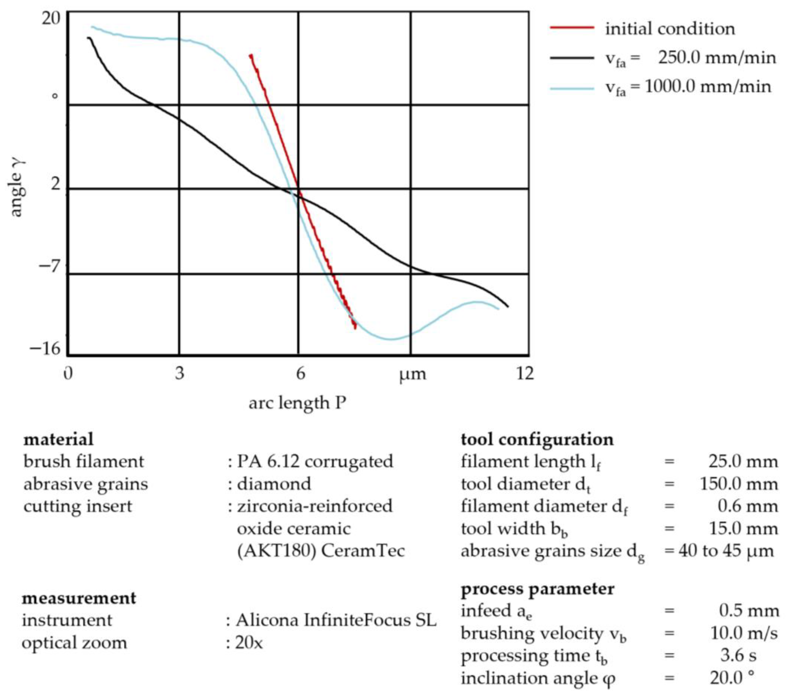
14]. The CEC represents the relationship between the arc length and the gradient. The zero point, which is defined as the intersection of the bisector line with an angle of α = 45° regarding the rounded cutting edge profile. As shown in
Figure 4, the CEC after brushing appears significantly smoother compared to the initial state, indicating a more uniform and consistent edge geometry following the brushing process. On the other hand, the cutting edge becomes wider due to material removal. It can be observed that an axial feed rate of v
fa = 1000 mm/min leads to discontinuities in the rounding process. The slight drop in the CEC indicates that the rounded edge becomes marginally smaller, meaning the local edge rounding radius r
β decreases. Under high axial feed rates v
fa, both the rake face and the flank face tend to become rounded with a comparatively large edge radius r
β, while the radius at the sharp edge itself changes only marginally.
The CEC theoretically reflects the tendency of a perfect edge rounding to approach a straight line, particularly when the transition between rake and flank surfaces is smooth and symmetric. However, with increasing brushing velocity vb, more material is removed from the cutting edge, leading to deviations from the ideal rounded geometry. As a result, the CEC becomes non-linear, capturing the imperfections or the asymmetry in the edge rounding geometry that a simple edge radius rβ or form factor K cannot fully describe.
Despite its descriptive power, the CEC is not a practical parameter for general evaluation of the brushing process. This is particularly true in the context of this study, which includes no reference experiments for the actual cutting performance of the brushed inserts. Without correlating the CEC variations to machining results, the added detail does not provide interpretive value yet. Therefore, for the purpose of assessing brushing behavior and process stability, the edge radius rβ and form factor K remain more practical and meaningful indicators.
The initial properties of the cutting inserts are shown in
Table 1. Due to the slight damage on the initial sharp edge, the standard deviation does not provide a reliable measure.
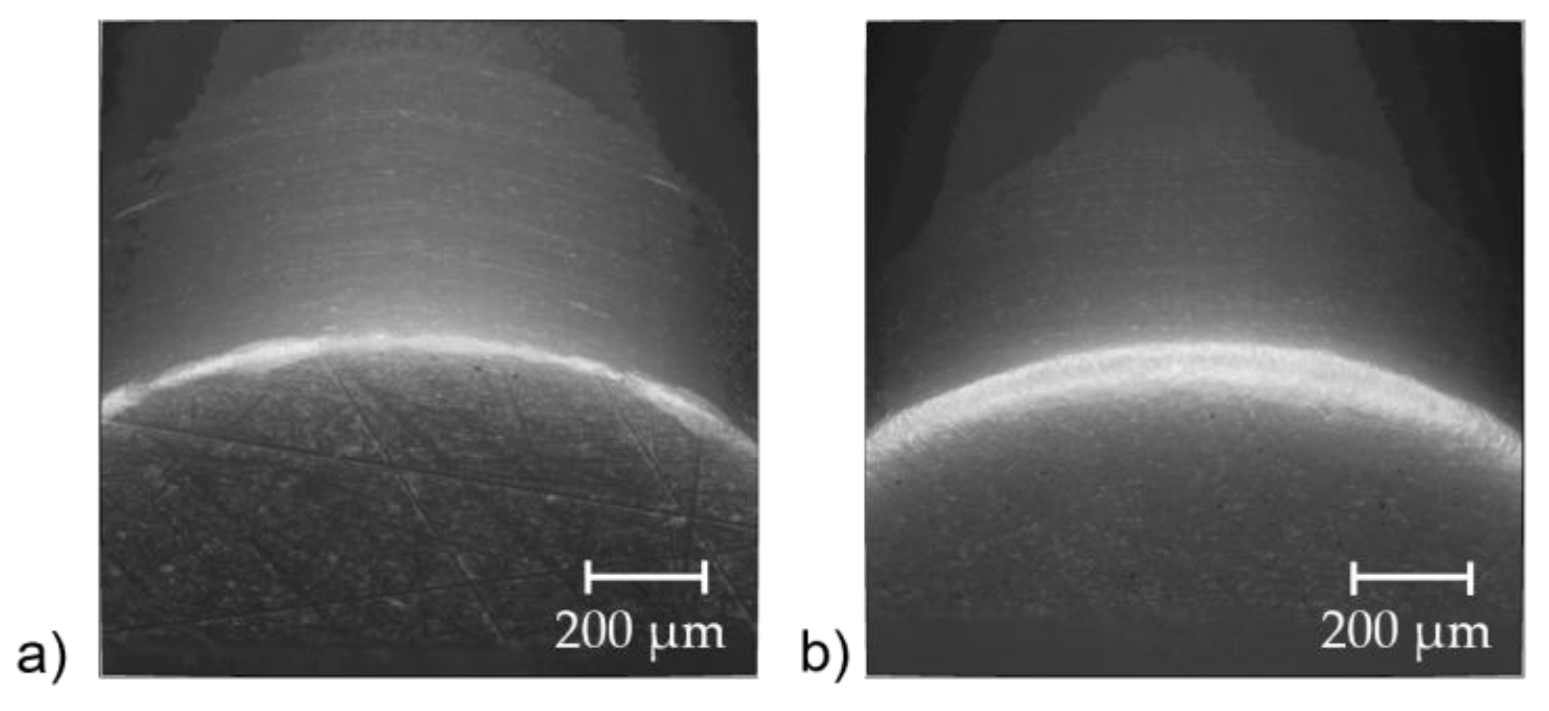
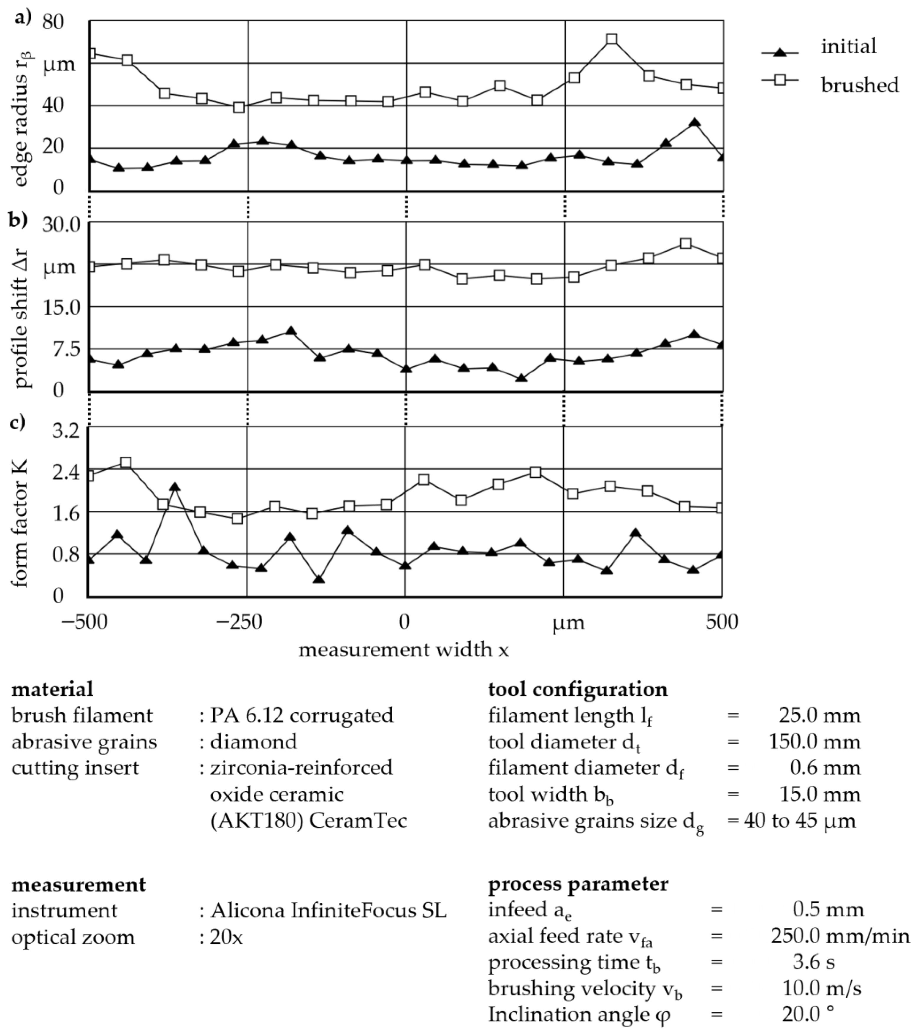
Figure 5a depicts the analysis of the initial cutting edge. The 3D datasets were sectioned tangentially along the cutting edge to evaluate key geometric parameters, including the variance of the edge radius r
β, the profile shift Δr, and the form factor K. Due to micro-chipping and manufacturing-induced irregularities, these characteristics showed noticeable variation and instability. After the brushing process, shown in
Figure 5b for a brushing velocity of v
b = 10 m/s, an axial feed rate of v
fa = 250 mm/min, and an infeed of a
e = 0.5 mm, an increase in the homogeneity and the edge radius r
β was observed, particularly in the central region of the cutting edge. The rounding generally shows a uniform characteristic, and no major defects were detected in the typical cross-sectional analysis. The variance of the profile shift Δr was also noticeably reduced. This improvement can be attributed to the elimination of micro-defects during brushing, which effectively stabilized the edge geometry. Additionally, sharp protrusions were removed early during brushing, resulting in a more consistent edge condition along the entire perimeter.
In the initial state, minor chipping along the cutting edge was observed as a result of the manufacturing process. Furthermore, grinding marks were present on the rake face, and fine particle residues, likely remnants from the sintering process, were visible on the flank surface. After brushing, the same cutting edge appeared considerably more homogeneous, with a notably smoother rake surface, indicating improved surface quality and uniformity of the edge geometry.
For the 162 experiments, a full factorial design was used, as shown in
Table 2. Each of the four experimental parameters, i.e., brushing velocity v
b, axial feed rate v
fa, infeed a
e, and brush inclination angle φ, was varied for each brushing tool, and experiments were repeated once to increase statistical robustness. The few large outliers were traced back to defects present in the initial state of the cutting tools. Minor micro-damage at the start of testing contributed to increased variability. In contrast, when the tools were confirmed to be free of initial damage, the results showed better reproducibility.
3. Results
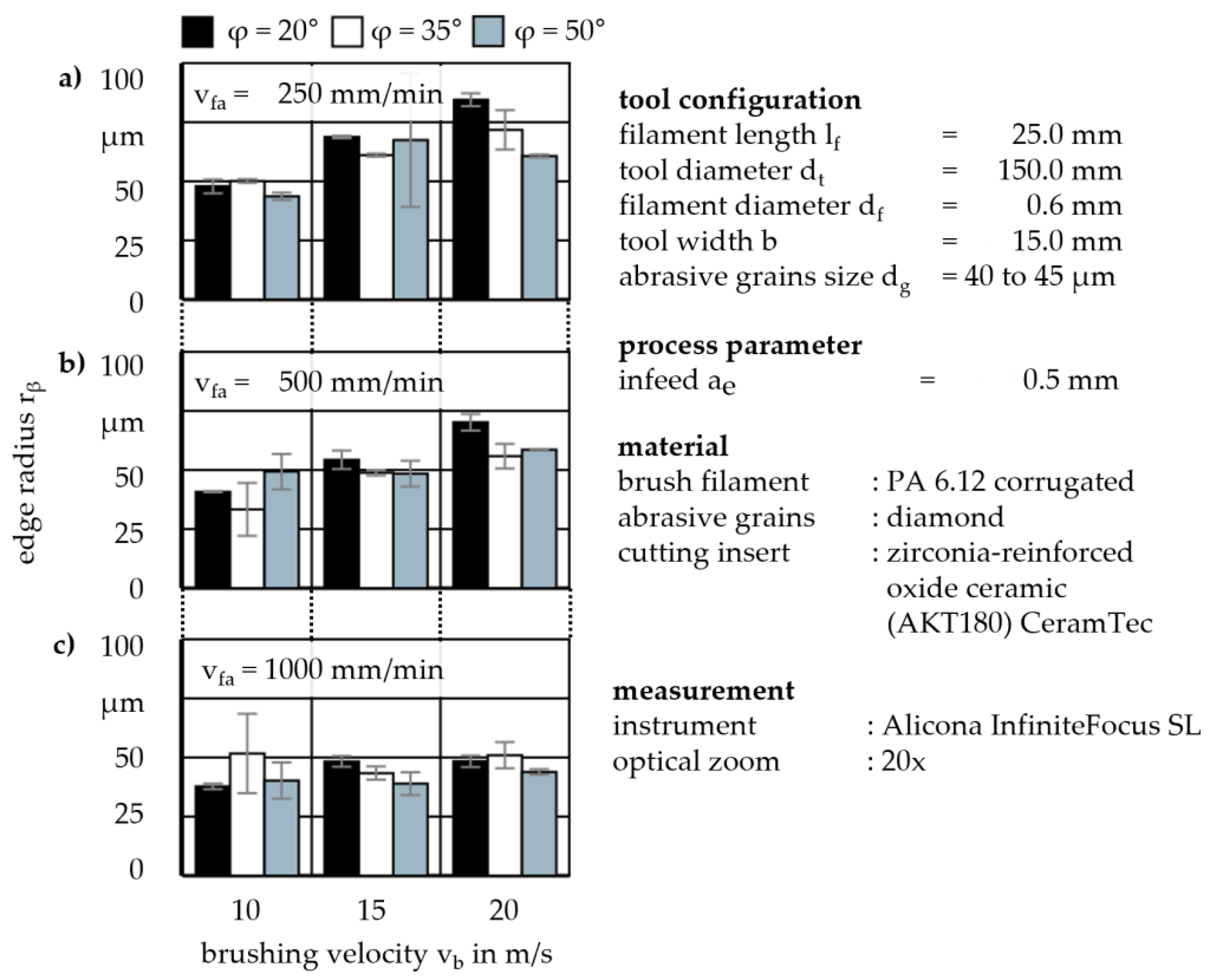
Figure 6 shows the edge radius r
β in dependence of the brushing velocity v
b at a fixed infeed of a
e = 0.5 mm for different axial feed rates v
fa.
At axial feed rates of v
fa = 250 to 500 mm/min, the edge radius r
β increases with the brushing velocity v
b for investigated brush inclination angles of φ = 20° and 35°. At an axial feed rate of v
fa = 1000 mm/min, this dependency decreases, and no systematic trend with the brushing velocity v
b can be identified. For a brush inclination angle of φ = 20°, the edge radius r
β increases consistently with an increasing brushing velocity v
b. In contrast, contact angles of φ = 35° and 50° exhibit no clear or systematic relationship with the brushing velocity v
b. The edge radius r
β increased, but not as substantially compared to φ = 20°. Similar effects of the brush inclination angle φ on the edge symmetry have been reported for diamond-filament brushing tools [
15]. Overall, the results demonstrate that increasing the axial feed rate v
fa suppresses the influence of brushing velocity v
b and brush inclination angle φ on the edge radius r
β.
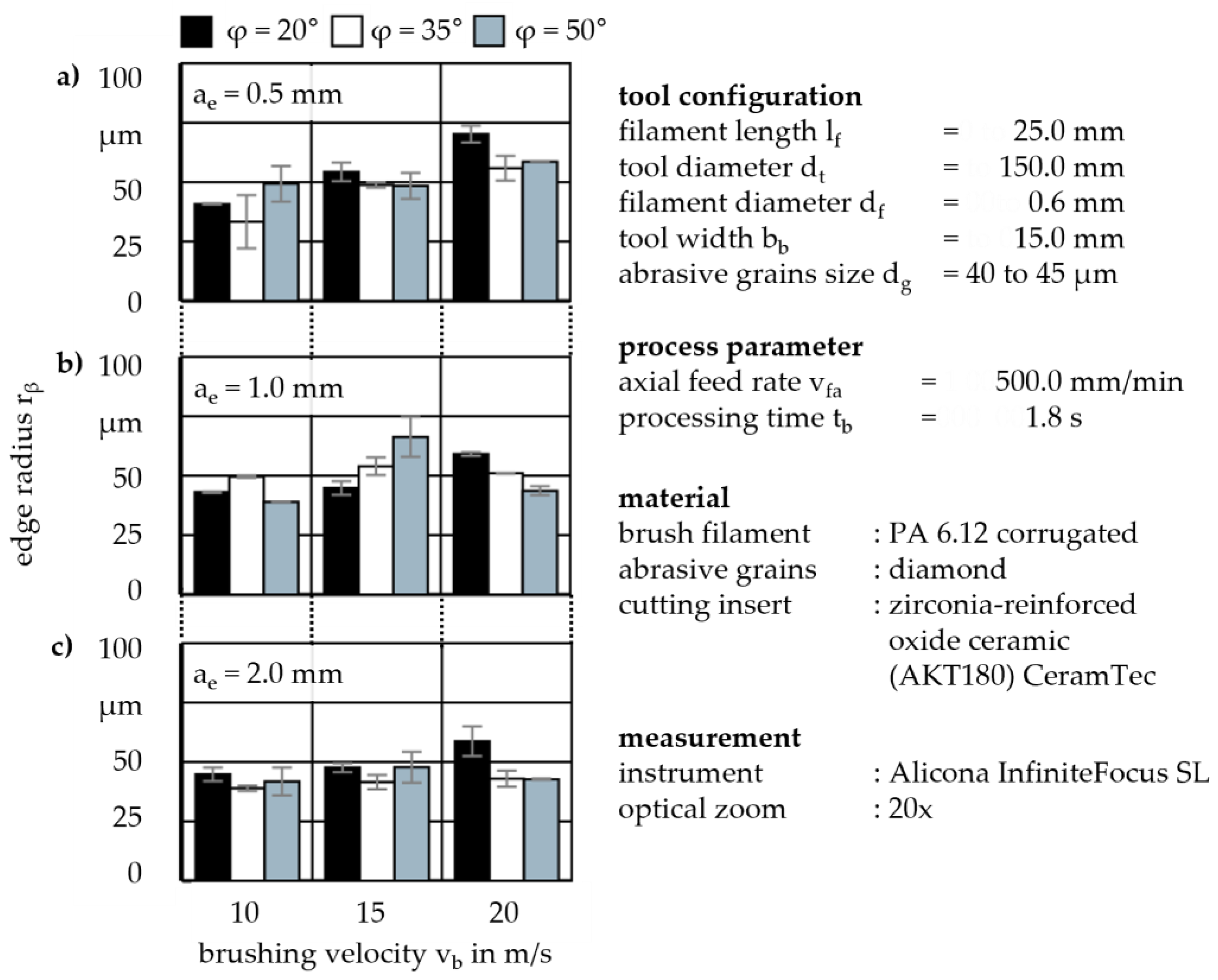
To showcase the dependence on the infeed a
e, experiments with an axial feed rate of v
fa = 500 mm/min are selected from the experimental dataset. Although it was already known that high axial feed rates v
fa reduce the sensitivity to other process parameters, the mid-range data still reveals a nonlinear relationship between the edge radius r
β and the infeed a
e. For example, in
Figure 7a, at an infeed of a
e = 0.5 mm, the edge radius r
β increases with the brushing velocity v
b for a brush inclination angle of φ = 50°. However, in
Figure 7b, when the infeed a
e is increased to a
e = 1 mm, the maximum edge radius r
β is reached at a brushing velocity of v
b = 15 m/s. With further increase in the infeed a
e, this behavior tends to decrease until it is almost unidentifiable. This phenomenon is facilitated by both the brush inclination angle φ and the infeed a
e. It can still be observed at v
fa = 1000 mm/min.
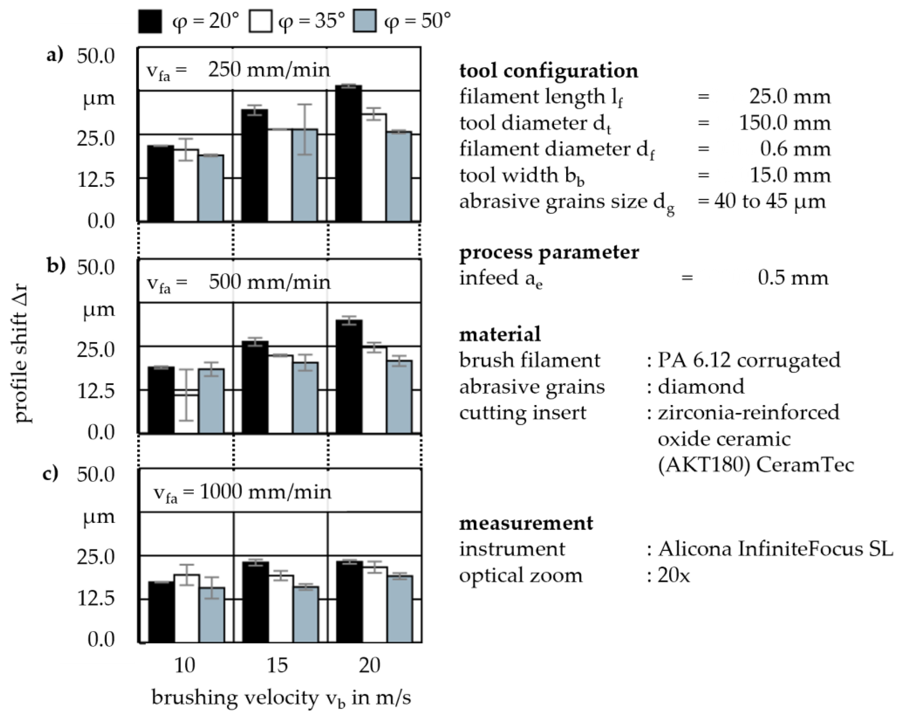
Figure 8 shows that the profile shift Δr exhibits trends comparable to those observed for the edge radius r
β. In particular, increased variance can be observed at a brushing velocity of v
b = 20 m/s, indicating reduced process stability at high brushing velocities v
b. The presentation of the results is limited to an axial feed rate of v
fa = 500 mm/min, for which the underlying tendencies are most clearly observable. At an inclination angle of φ = 20°, the dependence of the profile shift Δr on the brushing velocity v
b is most pronounced. This indicates that this inclination angle φ enables the most efficient material removal and edge rounding, largely independent from the form factor K. In comparison with the initial edge characteristics reported in
Table 1, not only does the edge radius r
β increase, but the profile shift Δr also exhibits a substantial and clearly observable increase. In contrast, at inclination angles of φ = 35° and φ = 50°, the increase in profile shift Δr appears to reach a quasi-stable state, with only minor differences between these two angles. Furthermore, variations in brushing velocity at inclination angles of φ = 35° and 50° have a limited influence on the profile shift when compared to φ = 20°. Nevertheless, the profile shift Δr continues to increase monotonically with the axial feed rate v
fa, which is directly correlated with the brushing time t
b due to the fixed brushing tool width of b
b = 20 mm.
In contrast to the edge radius r
β, the form factor K shows only a weak sensitivity to the brushing velocity v
b but a pronounced dependence on infeed a
e and brush inclination angle φ.
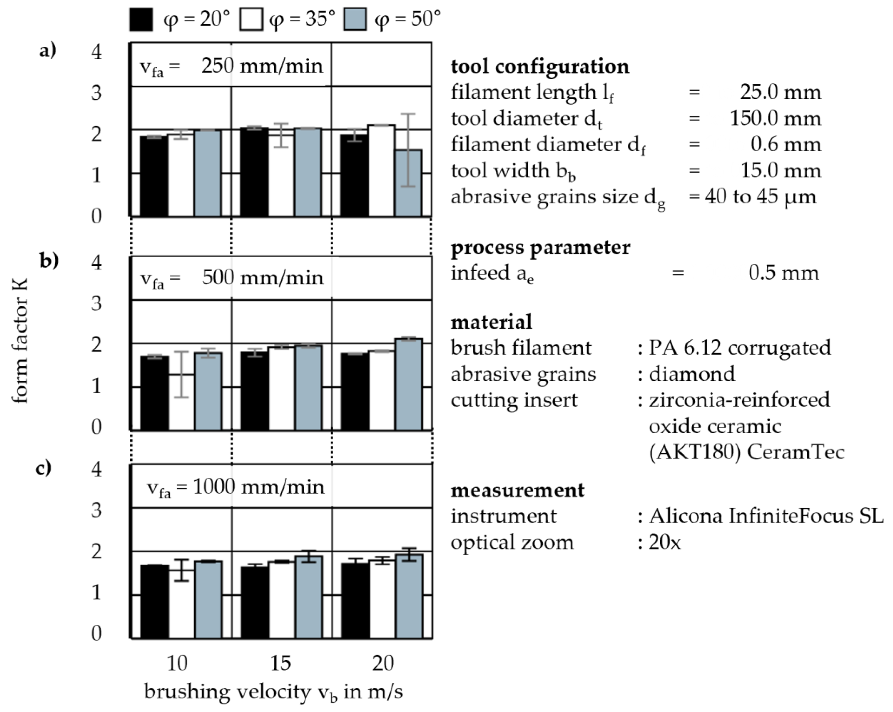
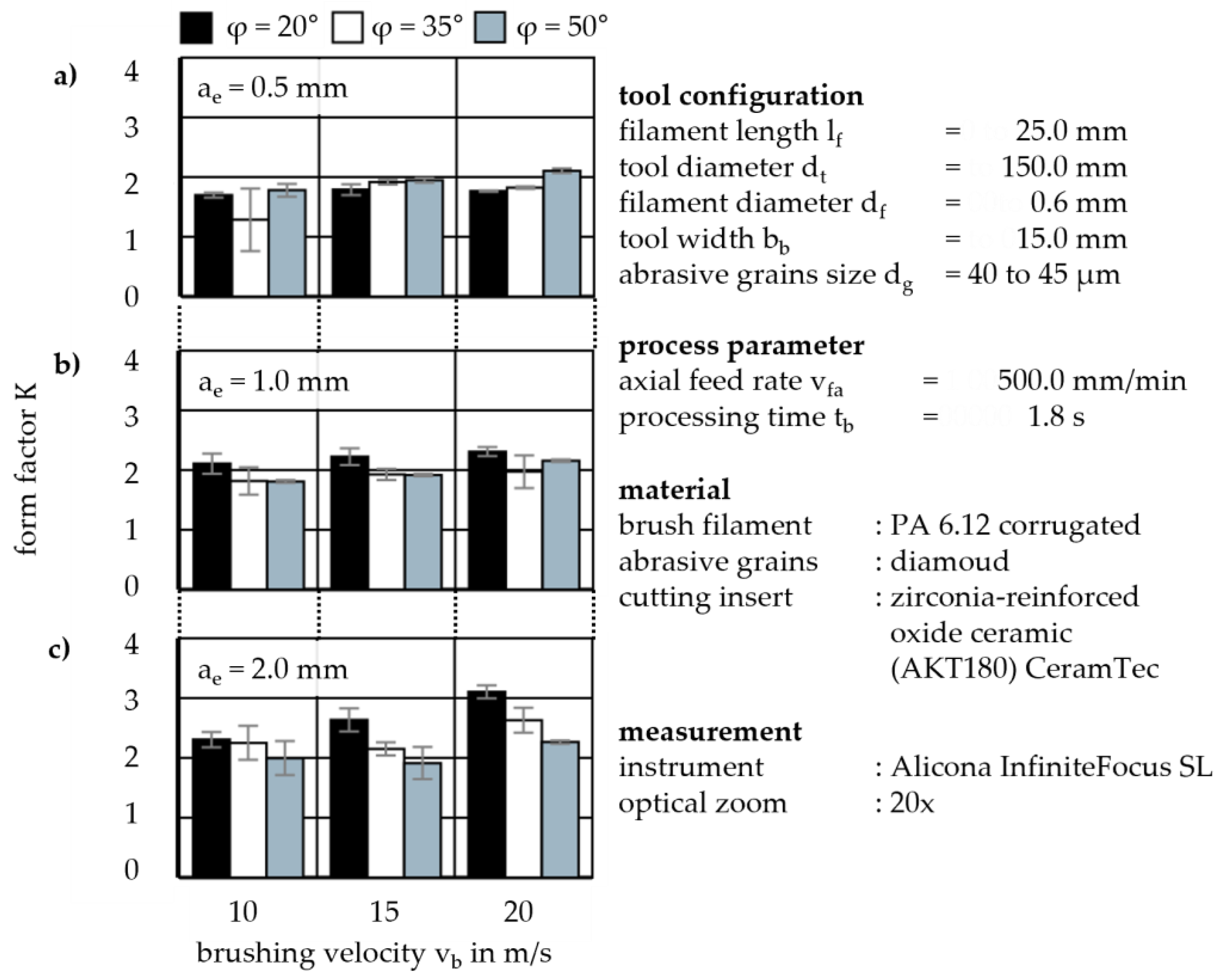
Figure 9 shows that increasing the axial feed rate v
fa results in a nearly constant form factor K under the same infeed of a
e = 0.5 mm. In this case, the form factor K remains nearly constant across all brush inclination angles φ. The reason for this is that the actual contact area between the brushing tool and the cutting insert is relatively small. As a result, almost no material is removed from the rake face. Thus, only the material near the edge area is removed. The inclination angle φ between the filaments and the cutting edge remains nearly unchanged throughout the brushing motion, since the variation in filament length l
f compensates for minor angular deviations. Owing to this effect and the small effective contact zone, the brushing process becomes largely insensitive to the inclination angle φ when the infeed a
e is small. Hence, the resulting edge rounding is primarily governed by filament stiffness and length distribution rather than by the inclination orientation.
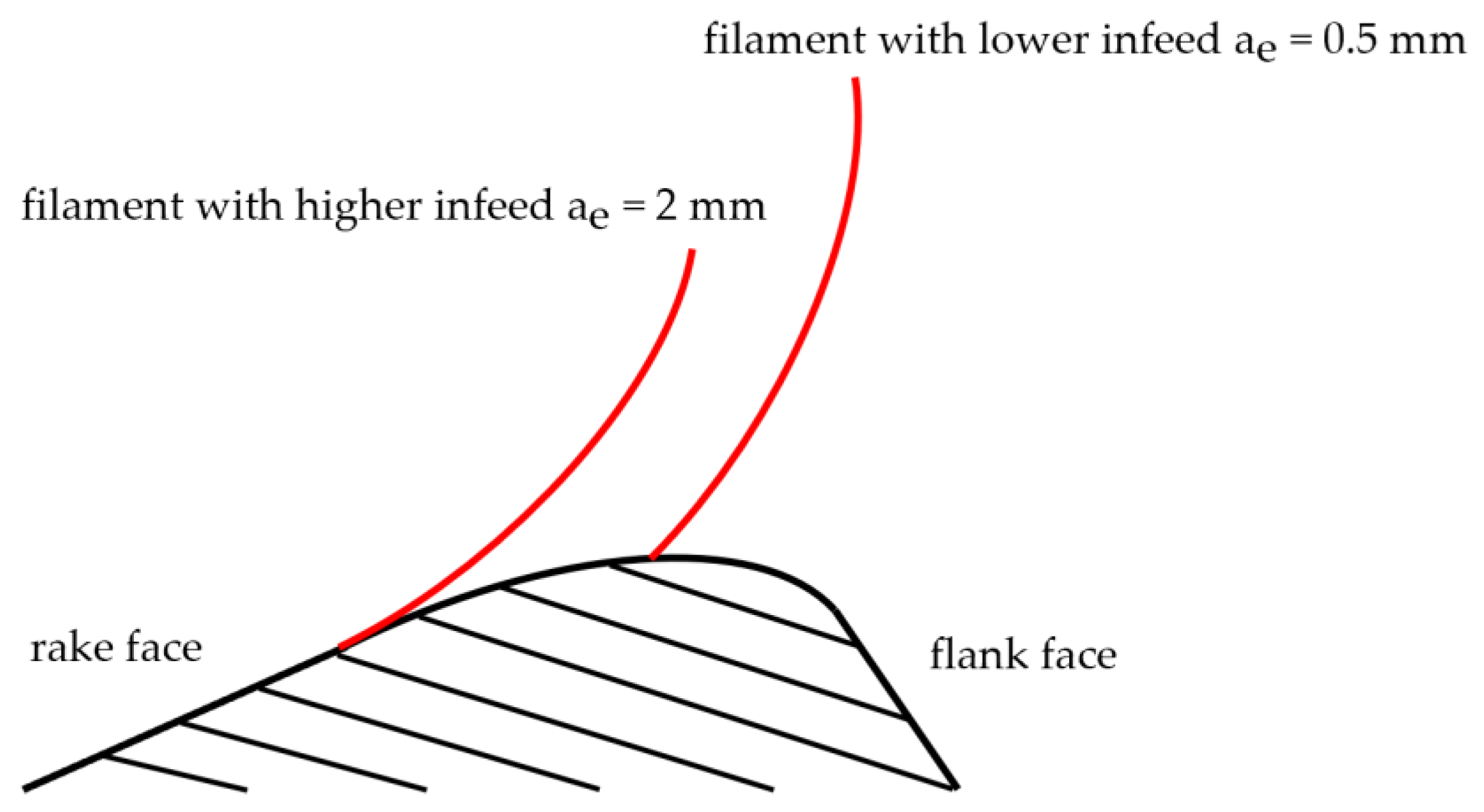
Although the filaments leave the cutting edge earlier, the longer brushing time t
b on the rake face shifts the effective contact zone further away from the cutting edge. As depicted in
Figure 10, the intersection point on the rake face shifts further from the cutting edge, diminishing its influence on the actual edge-rounding process.
Regardless of the approximated edge radius rβ, the form factor K shows no dependency when the infeed ae is small. Considering the variations in profile shift Δr and edge radius rβ within the same parameter range, it becomes evident that the largest differences at small infeeds ae occur in the central region of the edge, whereas only minor deviations appear near the edge of the brushed area. The insensitivity to the brush inclination angle φ is particularly notable.
The results in
Figure 11 demonstrate a clear dependency between the form factor K and the infeed a
e. At larger infeeds of a
e ≥ 1 mm, the form factor K becomes strongly dependent on the brush inclination angle φ, with smaller brush inclination angles φ producing larger form factors K.
The results show that the form factor K is largely insensitive to the brush inclination angle φ at small infeeds a
e while a strong dependence on the brush inclination angle φ can be observed at large infeeds a
e. In contrast to the edge radius r
β, the form factor K is less affected by the brushing velocity v
b and is primarily influenced by the location of material removal relative to the cutting edge. Although the measurement position cannot be guaranteed to be identical for every sample, the deviation remains within Δl = 100 µm. Thereby, it can be assessed how strongly the initial state affects the processed edge radius r
β. In
Figure 12a. The zero position on the
x-axis corresponds to the tip of the cutting edge. On both sides of the rake-flank boundary, two small initial defects were present. After brushing, these defects remained at the same locations, indicating that the brushing tool is not capable of completely equalizing such micro-damage, at least not within the range of process parameters investigated in this study. The profile shift Δr in
Figure 12b becomes more stable after brushing. The variance of the profile shift Δr along the cutting edge is clearly reduced by the process, suggesting that brushing contributes to a homogenization of the edge geometry. As
Figure 12c shows, the effective lengths of the rake and flank faces increased, leading to a reduction in the sensitivity of the form factor K compared to the initial state. The form factor K is also considerably stabilized. Maintaining a sharp cutting edge is inherently difficult, as even small initial defects can produce large deviations in the form factor K. Continuous material removal during brushing not only generates a more uniform profile shift Δr along the edge but also makes the form factor K less sensitive to variations in the initial edge condition. Localized initial defects remain detectable at the same edge positions after brushing, indicating that the process homogenizes the edge geometry globally but does not completely eliminate pre-existing micro-damage.
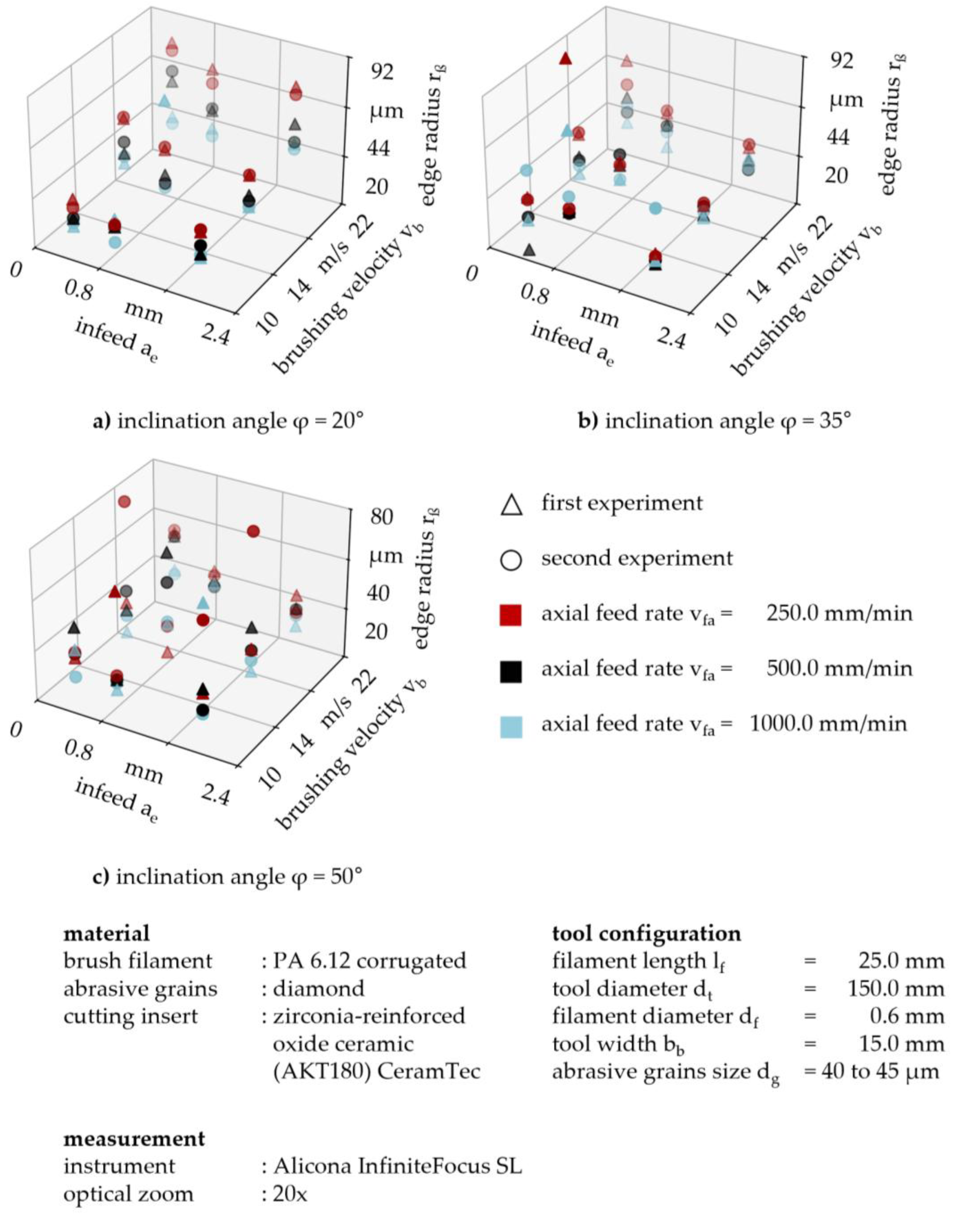
Figure 13 reveals a systematic difference between first and repeated experiments conducted under identical process parameters. Triangle markers indicate the first experiment for a given parameter set, whereas circle markers represent the corresponding repetition. The consistently lower edge radii r
β in the repeated experiments indicate progressive brushing tool wear despite pre-conditioning on a planar Al
2O
3 workpiece. Although the cutting edge condition exhibits minor variability, a consistent trend becomes apparent, with the triangle markers generally positioned above the circle markers. This indicates that the results were influenced by the cumulative tool usage time t
e. As the brushing tool is used for long periods, its capability to produce a consistent edge rounding reduces continuously. This systematic offset suggests an influence of brushing tool wear. Nevertheless, the effect becomes clearly distinguishable only at elevated axial feed rates v
fa. At low axial feed rates v
fa, the effect of brushing tool wear is negligible compared to the variability introduced by the initial edge condition.
Although a full factorial experimental design was employed, the present study focuses on trend analysis rather than statistical modeling. Future work will include variance analysis and interaction modeling to derive predictive relationships for industrial applications.
4. Discussion
The results of this study demonstrate that abrasive brushing is a suitable method for preparing ceramic cutting edges, even in the presence of small initial defects that commonly occur during tool manufacturing and handling. Although the initial condition of the cutting edge introduces some variability, the brushing process notably reduces profile variance along the cutting edge and stabilizes important edge metrics such as the form factor K. This stabilization reflects the transition from a defect-sensitive sharp edge to a controlled, homogenized rounded edge produced through continuous material removal. To achieve a continuously adjustable form factor K starting from K = 1, additional experiments with different brushing directions and a wider range of brush inclination angles φ are required.
The observed trends in
Figure 6,
Figure 7 and
Figure 8 can be explained by the material removal mechanisms typical for ceramic brushing processes. Unlike metallic materials, ZTA primarily undergoes brittle fracture and micro-chipping rather than plastic deformation. Similar brittle-dominated removal has been observed during abrasive adjustment of dental ceramics [
16] and alumina-zirconia abutments [
17]. Material removal is governed by the interaction between filament stiffness, abrasive grain penetration depth, and the local stress state at the cutting edge. This interaction is consistent with fracture-erosion and indentation-fracture models of brittle material removal [
18,
19]. At low axial feed rates v
fa and low brushing velocities v
b, repeated low-energy impacts promote controlled micro-fracture, leading to gradual and homogeneous edge rounding. At high brushing velocities v
b or infeeds a
e, increased impact energy and filament deflection reduce process stability, resulting in a higher variance of the edge radius r
β and the profile shift Δr. Similar instability under high energy conditions has been attributed to grain scale fracture and chipping in ZTA [
20,
21].
The behavior seen in
Figure 6 appears to result from the combined influence of infeed a
e and brush inclination angle φ. During the brushing process, the tool first engages the rake face and subsequently moves toward the cutting edge, which contributes to the observed rounding characteristics. Increasing the brush inclination angle φ leads to an increased rake-surface contact area, which can modify the motion of the filaments. As a result, they may be deflected sideways and are less likely to engage the cutting edge efficiently. A key finding from
Figure 7 is the nonlinear relationship between the edge radius r
β and the infeed a
e. At low infeed a
e, no clear dependency is observable. However, as the infeed a
e increases, the interaction between brushing velocity v
b, brush inclination angle φ, and edge radius r
β becomes more pronounced. Under these conditions, the maximum edge radius of r
β = 87 µm was obtained at inclination angle φ = 20°, infeed a
e = 0.5 mm and. These results show that, at this parameter combination, the filament dynamics may enter an oscillatory regime. This interpretation is based on observed process trends and is not directly measured in this study. That phenomenon explains why certain parameter combinations show weak rounding tendencies despite high process intensities. This is consistent with the force-penetration relationships described by Uhlmann and Hoyer [
6]. Due to the elastic behavior of the filaments and their initial contact on the rake face, the filaments deflect, which increases their potential energy and reduces their kinetic energy. Despite the inherent damping of the filaments, further research is required to understand this dynamic behavior, specifically, whether the filaments intermittently detach from the cutting edge or instead maintain continuous sweeping contact along it, and how both interaction modes influence the resulting edge geometry. This dynamic instability of filaments at a brushing velocity of v
b = 20 m/s has been demonstrated in DEM simulations [
10].
Figure 8 showed results for the profile shift Δr. Brush inclination angles of φ ≥ 50° reduce the effectiveness of filament impacts due to energy absorption on the rake face, which in turn limits material removal near the cutting edge. In principle, a large number of filament edge contacts should result in an increased profile shift Δr.
The brush inclination angle φ shows negligible sensitivity to the form factor K if the infeed is a
e = 0.5 mm,
Figure 9, as the filament has only a limited influence on material removal at the flank face. The effect of the rake face resulting from different brush inclination angles φ is not particularly pronounced. This can be attributed to the relatively short contact time t
c between filament and workpiece.
On the other hand, the brush inclination angle φ is strongly correlated with the form factor K if the infeed is a
e ≥ 0.5 mm,
Figure 10, because at larger brush inclination angles φ, the filaments show reduced ability to brush the edge efficiently because they bend easily, preventing their kinetic energy from being fully transferred to remove workpiece material. The filaments’ kinetic energy is absorbed by the rake face as the impact occurs slightly further from the edge. As a result, the localized stress at the edge is reduced, leading to diminished material removal. The reduced profile shift Δr at large brush inclination angles φ indicates that the edge material is removed less effectively under these conditions. The material on the edge clearly is reduced less. Conversely, when the brush inclination angle φ is small, the filaments exhibit a reduced likelihood of contacting the flank face. After passing over the cutting edge, the filaments require a short time interval before re-establishing contact with the flank face. A small brush inclination angle φ causes this contact to break abruptly and prevents the filaments from effectively reattaching. This leads to increased material removal on the rake face side compared to the flank face.
An additional systematic effect was observed during experiment repetitions. The first experiments consistently produced slightly larger edge radii rβ than the repetitions under identical parameters. This trend suggests an influence of brushing tool wear. However, the effect becomes distinguishable only at high axial feed rates vfa. Otherwise, it is negligible based on the variability resulting from the initial cutting edge condition. Nonetheless, long-term brushing tool wear during ceramic cutting edge preparation remains to be investigated.
From a practical perspective, the findings highlight both the strengths and limitations of brushing as an industrial edge preparation method. Brushing is capable of smoothing out micro-defects and generating globally uniform edge geometries along the full perimeter of an indexable insert, which is difficult to assess through microscopy alone. At the same time, the method cannot fully eliminate localized micro-damage at the start of the process, indicating that certain defect types from previous manufacturing steps persist.