1. Introduction
The class of transition metal nitride coatings has proved to be beneficial in improving the useful service life of the components in the metal tool industry. The performance of the coated components in various engineering applications is largely dependent on not only the tribological characteristics of the coatings but the bonding (adhesion) strength between the coating and the substrate. The adhesion can be improved by adequately controlling the coating process parameters and modifying the substrate prior to the deposition of the coating.
Protective surface coatings prepared by physical vapour deposition (PVD) have been effectively used in mechanical components to increase their lifetime. CrN coatings possess wide application due to their excellent mechanical properties [
1,
2], low friction coefficient, high hardness, wear resistance [
3,
4], chemical inertness [
5,
6], superior oxidation resistance at high temperatures up to ~700 °C, or corrosion resistance under severe operating conditions. These coatings provide excellent abrasion resistance [
7]; thus, they are used as cutting, milling, and screw threading tools. Using CrN coatings, a considerable reduction of ejection forces or cavity pressure is achievable in injection moulding; therefore, they are preferred as protective coatings for tool cores, punches, or dies [
8] and in various other tribological applications [
9]. TiN coatings having large-scale application in the 1980s–1990s were replaced by CrN coatings in the 1990s–2000s due to their better wear performance in dry and lubricated conditions [
9,
10,
11], higher oxidation resistance at elevated temperatures, better thermal stability, corrosion resistance, and three times higher achievable deposition rate [
12] compared with that of TiN or Ti-C-N coatings [
13].
The unique combination of mechanical and physical characteristics can significantly impact the tribological performance of a coated system, that is, a more favourable combined response of the substrate and the surface layer under a wear type of loading. The performance of the coated systems can be significantly improved by duplex treatment [
14], which combines two or more surface technologies to produce a composite surface on the component with improved loadability and durability, not achievable by the individual processes alone. This improvement indirectly leads to a considerable cost reduction and increases the productivity of the manufacturing technologies applying tools with duplex-treated surfaces [
15].
Plasma nitriding is an advanced and versatile tool for the thermochemical treatment of steel, widely used in the industry. A duplex treatment consisting of plasma nitriding the substrate followed by ceramic coating deposition represents an effective solution to improve the wear resistance, hardness, and durability of a coating/steel substrate material system [
16,
17]. The diffusion of nascent nitrogen into the surface layer results in a nitrided layer consisting of two structural zones. The compound layer consists of ε(Fe
2–3N) and γ′(Fe
4N) nitrides formed by the alloying elements with the basic constituents, while the diffusion layer contains interstitially solute N atoms along with fine and coherent precipitates of nitrides, where the solubility limit is exceeded. The nitrided layer provides several advantages, such as increased surface hardness, better corrosion and fatigue resistance, or reduced wear and friction [
18,
19], which is utilised as a sublayer in duplex-treated coatings.
The base material investigated in the current research is a high-alloy plastic mould tool steel designed to cater to the requirements of die casting and plastic injection moulding dies in polymer processing. It requires good machinability, high strength, toughness, corrosion resistance, high wear resistance, and good photoetching characteristics. The increasing demand for this steel in the automobile, mechanical, and structural component industries triggered intensive research and development of these steels. The material properties desired in these applications can be efficiently improved by plasma nitriding; however, the material’s response to nitriding depends on several parameters, such as substrate composition, treatment time, temperature, and nitrogen potential.
Alloying elements such as Al, Ti, Cr, V, and Mo can interact with nitrogen to form nitrides, which affect surface hardening. The investigated X42Cr13 steel has a high chromium content. It is known that a Cr content below 5.6 wt% has an intermediate effect on N diffusion during nitriding. At the same time, above this value, a strong interaction between Cr and N occurs [
20], resulting in the formation of CrN precipitates that limit the nitrogen diffusion into the surface layer and significantly reduce the achievable hardness, besides causing high tensile residual stresses.
This nitriding issue has been a critical obstacle to the broader-range application of such high Cr steels. Several researchers have dealt with this problem [
21,
22], and they suggested the reduction of the nitriding temperature to below 450 °C [
23] and applying a long-term nitriding [
24] to avoid overaging during nitriding of the precipitation-hardened steels of high hardness (470–550 HV) obtained by a tempering temperature below 500 °C. In contrast, when lower hardness/higher toughness is the purpose, realised by a tempering temperature greater than 500 °C, better wear resistance can be reached by applying a nitriding temperature above 520 °C and shorter (~4 h) holding times. In this case, there is no risk of overaging [
20], but other undesirable consequences of the treatment—delayed cracking [
25], increased sensitivity to corrosion [
24], steep hardness profile, or lower case-depth—may occur. Studies on this nitriding problem are available mainly for the steels of AISI 420 type, mainly focusing on the corrosion resistance of low-temperature nitrided martensitic stainless steels [
26,
27,
28,
29,
30]. A minimal amount of studies on wear resistance of high Cr steel treated by high-temperature nitriding [
27,
28] is found, and to the best of the authors’ knowledge, no results on the nitriding problem and wear resistance of the X42Cr13 steel have been reported up to now.
Adhesion of the coating to the substrate plays a vital role in the successful application and durability. There are several techniques to evaluate the adhesion strength of the coating. The scratch test is one of the most reliable and efficient standardised methods for determining the L
C critical load, causing the delamination of the coating from the substrate [
31]. This critical load is a function of several factors, such as the mechanical properties of the coating and the substrate, the adhesion strength between them, the coating thickness, the internal stresses in the coating or the subsurface region, or the flaw size distribution at the substrate–coating interface [
32]. Furthermore, the measured critical load depends on the loading rate, scratching speed, load gradient, stylus tip radius, or friction between the stylus and the coating [
33]. However, the critical load is constant if the load gradient is constant [
34], regardless of the loading rate and scratching speed, which allows for a comparison of scratch test results carried out with different test parameters but identical load gradients. In coated systems, a decisive role is played by the composite hardness of the coated material system influenced by the hardness of both the coating and the substrate, as well as the hardness gradient between them. The critical force derived from the scratch test can also be correlated directly with this composite hardness [
35,
36].
Wear is a damaging process involving progressive material loss that takes place due to the interaction of surfaces being in relative motion. During wear, within the area of contact, several physical and chemical elementary processes between the sliding pairs occur, leading to changes in the material structure and the shape of the frictional counterparts. Under a given loading, usually, more wear mechanisms operate simultaneously, and the damage process is controlled by the dominant one, which is possible to identify by analysing the wear track morphology using optical or electron microscopy. For quantitative characterisation of the wear resistance, several wear tests are available. The ball-on-disk method is one of the most frequently used standardised test procedures [
37]. Similar to the case of scratching, the wear damage process, the controlling damage mechanisms, and the wear resistance of the tribosystem are also influenced by several extrinsic and intrinsic factors [
38,
39,
40,
41].
The current research focuses on the effect of the applied duplex treatment on the tribological performance of CrN coatings deposited on the investigated high Cr content tool steel (X42Cr13).
Tribological analyses—either wear or scratch tests—accomplished on tribosystems constituted by the combination of the studied substrate and coating materials have not been reported in the professional literature. Some tribological studies on coated systems with AISI 420, that is a similar substrate material, are available [
29,
30,
42,
43]. However, AISI 420 and X42Cr13 have compositional differences in terms of C and other alloying elements, such as V, Mo, Ni, Cu, and Al, which influence both the results of the surface modification (nitriding) technology and the tribological behaviour of the coated system. It should also be noted here that the tribological results for AISI 420 steel found in the literature refer to AISI 420 steel grades with a very diverse chemical composition in terms of the listed constituents, so in some cases, they are difficult to compare with each other and with the results presented in this research.
This study on the influence of the duplex treatment on the scratch and wear resistance of the applied CrN coating deposited on a high Cr steel substrate is a novel contribution to the topic and presents the first-ever results on trybosystems with high Cr, secondary-hardened, martensitic stainless-steel substrates, therefore may attract the attention of tribologists and material scientists.
2. Materials and Methods
Test samples were made of X42Cr13 plastic mould tool steel of the following chemical composition (wt%): C = 0.40, Si = 0.42, Mn = 0.38, P = 0.021, S = 0.002, Cr = 13.1, V = 0.03, Ni = 0.17, Cu = 0.12, Al = 0.019, and remaining is Fe. Disc-shaped samples of φ30 mm × 10 mm were cut from a commercially available annealed steel road and sectioned using a universal lathe machine. It was followed by grinding to refine the dimensions and geometric shape, for example, the parallelism of the surfaces. Then samples were sonicated with acetone to remove dirt and grease; then holes of φ3 mm in diameter were created by drilling to hang the samples during nitriding. Finally, samples were given an identification mark.
Samples were subjected to bulk heat treatment of secondary hardening, consisting of austenitising and oil quenching, followed by a high-temperature tempering. Austenitisation was accomplished at a temperature of Taust = 1020 °C for a time of taust = 20 min, and double tempering at Ttemp = 580 °C for the duration of ttemp = 2 h. After bulk heat treatment, the samples were divided into two categories. One set of the samples, denoted by (S), was not nitrided, only ground and polished, then coated by a hard CrN layer deposited by PVD. During grinding, SiC papers with a grit size of P400, P1000, and P1500 were used, and for polishing, Al2O3 suspension of a grain size of 0.3 μm was applied. The other set of samples, denoted by (D) and called duplex treated, was nitrided in a plasma nitriding equipment (type Nitrion 10, from SC PLASMATERM SA, Targu Mures, Romania) at a temperature of Tnitr = 520 °C, for a holding time of tnitr= 8 h. The primary voltage was 600 V, and the pressure was 200 Pa. The source of nitrogen was decomposed ammonia (N2:H2 = 1:3). Thus, the S (simply coated) samples are secondary-hardened + PVD coated specimens, while the D (duplex-coated) samples are secondary-hardened + nitrided + PVD coated test materials.
CrN coating is deposited using PVD magnetron sputtering, assisted by the microwave technique. Microwave increases the quantity and the kinetic energy of Ar ions. The equipment used was TSD 550 (from HEF Durferrit M&S SAS, Andrézieux-Bouthéon, France). The steps involved are as follows: First, a Cr adhesion layer was deposited using a Cr target (99.99%) in Ar (60 cm3/min). The nitrogen gas flow was controlled by light measurement (luminosity), a chamber working pressure of 0.3–0.5 Pa using a pulsed DC sputtering power source, held at 6 kW. A bias voltage of 100 V was applied to the substrates. The thickness of the CrN layers was controlled by adjusting the deposition time. The substrate temperature was 400 K, resulting from the bombarding species only. The deposition rate for the CrN films was 1.5 μm/h.
The elemental distribution in the near-surface layer was defined by glow discharge optical emission spectroscopy (GDOES) using the equipment of GD-Profiler 2 (from HORIBA Jobin Yvon, Montpellier Cedex 4, France). Test parameters were as follows: RF generator, flushing time: 5 s, preintegration time: 60 s, depth: 66.966 μm, pressure: 500 Pa, power: 25 W, module: 6 V, phases: 5 V.
The hardness of the samples with different treatment conditions and the composite hardness of the coated systems, furthermore the near-surface hardness profile of the nitrided layers, were determined by the standard micro-Vickers test (with Mitutoyo HVK-H1 hardness tester from Mitutoyo Corp., Kanagawa, Japan) with normal loads of F = 1 N and 0.5 N. The thickness of the coatings was defined by the ball cratering method using a Compact CAT
2c Calotester from Anton Paar GmbH, Graz, Austria [
44]). The tests were performed with a φ30 mm quenched steel ball and a rotational speed of n = 3000 1/min for t = 3 min.
Optical microscopy (OM) using a Zeiss Axio Observer D1m type inverse microscope from Zeiss, Jena, Germany, and scanning electron microscopy (SEM) using a Zeiss Evo MA10 machine equipped with energy dispersive X-ray spectroscopy (Zeiss, Jena, Germany) was used to reveal the microstructure of the samples of different—secondary-hardened, nitrided, and coated—conditions. Secondary electron (SE) and backscattered electron (BSE) imaging during the SEM were used for detailed morphological analyses of the scratched and worn surfaces and to visualise the microstructural features of the nitrided surface.
For evaluating the adherence of the coatings, an instrumented scratch tester (type SP15, from Sunplant, Miskolc, Hungary [
45]) was used by applying a progressive loading scratch test, widely used for rapid assessment and quality assurance of surface coatings [
31]. During this test, a standard HRC diamond cone, as a stylus, is moved over the coated surface with a linearly increasing load, which varied from 2 to 150 N in the current study. The velocity of the sample holder table, moving below the stylus, was 5 mm/min, and the gradient of the normal force was 10 N/mm. The critical force at which the coating failure, that is, delamination, occurs can be found from the friction coefficient-loading force versus the scratching distance diagram recorded by the test machine. Failure modes (damage mechanisms), occurring at and below the critical forces, were identified by morphological analyses of the scratch grooves using OM and SEM.
The wear resistance of the coatings was investigated using a ball-on-disk test (equipment: UNMT-1, manufacturer: Center for Tribology, Inc., CETR, Campbell, CA, USA). The friction counterpart was a SiC ball of φ6 mm in diameter, the normal load was 20 N, the total sliding distance was 108 m, the radius of the wear track was 3 mm, and the sliding rate was 30 mm/s. The integrated software program recorded the values of the coefficient of friction as a function of sliding distance. The specific wear rate (k) was calculated according to Archard’s equation [
46]:
where
A (mm
2) is the worn cross section obtained from profilometry (with Altisurf 520 surface tester using a confocal head from Altimet, Thonon-les-Bains, France),
F (N) is the normal load,
Lt (m) is the total sliding distance, and
C (mm) is the length of the wear track centreline.
During the hardness test, the scratch tests, the coating thickness measurements, and in the case of determining the hardness profiles of the nitrided layer, three valid measurements on two samples of both the simply and duplex-coated test groups were accomplished. Wear tests with the given test condition were performed on two samples accomplishing two measurements per sample. During profilometry, the wear tracks were scanned along four mutually perpendicular directions of the circumferential worn track. The average of these four data for each worn track is represented by At, while the A value is the average of the At values obtained on two worn tracks created on one sample. The ball cratering thickness tests were performed three times on two samples.
3. Results and Discussion
3.1. Microstructural and Compositional Characterisation and Hardness
After the bulk heat treatment, the secondary-hardened microstructure consists of a martensitic matrix containing high Cr content precipitates, which are usually Cr
23C
6- and (Cr, Fe)
23C
6-type carbides [
47]. The dimensional stability is provided by the low amount of residual austenite, characteristic of the given microstructure in the case of the applied tempering temperature [
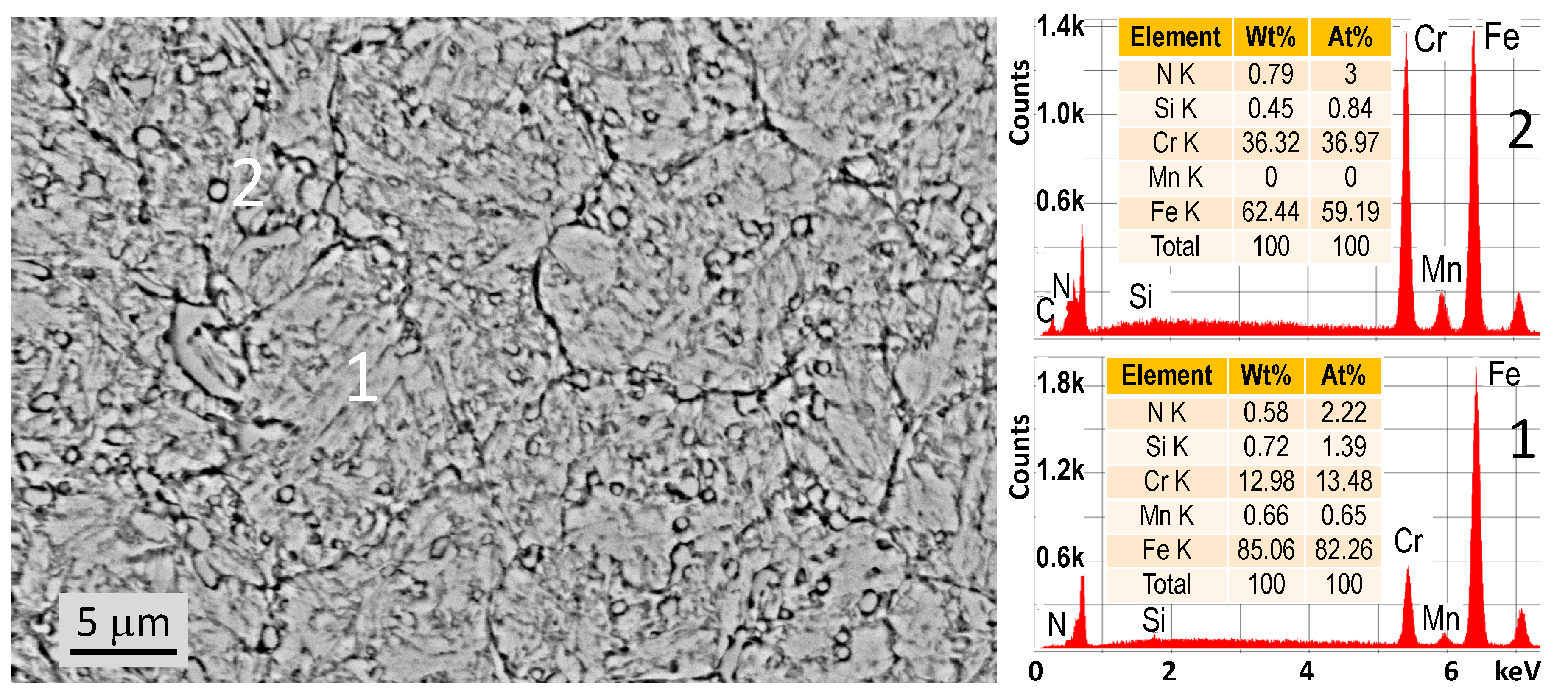
48]. A SEM image of the microstructure combined with EDX compositional analyses in two spots is shown in
Figure 1.
Spot 1 is indicative of the tempered martensitic matrix, with an amount of alloying elements corresponding to the composition of the raw material. Spot 2 shows a Cr-rich precipitation with higher C content, suggested by the C peak appearing in the related EDX spectrum that is not observed in Spot 1. Compared with the maximum (540 HV) hardness achievable for this steel, the applied bulk heat treatment results in a lower—HVPH = 290 HV0.1 ± 4.7—substrate hardness, providing higher toughness and better dimensional stability. It is applied primarily in structural components, as well as in the case of tools, where good toughness is more important than high hardness. In the current study, the bulk heat treatment parameters were chosen to avoid the significant hardness reduction, dimensional inhomogeneity, and high residual stresses that are possible to occur during subsequent nitriding.
A SEM cross-sectional image and the hardness profile of the nitrided layer (520 °C, 8 h) are shown in
Figure 2. The microstructure of the nitrided layer contains a large number of precipitates along the prior austenite grain boundaries and in the bulk, which is characteristic of high Cr steels. The most common type of these precipitates is CrN, hindering the N diffusion strongly and resulting in a flat hardness profile shown in
Figure 2, and may cause high tensile stresses [
26,
49]. The surface hardness measured after removing the white layer—and before the coating process—was 360 HV
0.05 ± 37, which dropped sharply below the surface towards the core. The nitrided layer thickness,
hN = 40 ± 5.6 μm, was small.
The nitrogen and chromium distribution obtained by GDOES in the near-surface layer (
Figure 3) explains the hardness profile shown in
Figure 2.
The nitrogen content decreases sharply in the 0.5–1 μm depth region and approaches 0% at the deeper locations. It is reasoned by the intermediate nitriding temperature, resulting in a low penetration depth of the nitrogen atoms responsible for the moderate surface hardness after nitriding. Obtaining a thicker and harder layer would require an increase in the nitriding temperature and holding time. The Cr peak, observed at a 0.8 μm depth, appears supposedly due to the strong gradient of the N distribution in this region. Since there is no significant amount of N at higher depths that would attract the Cr atoms, Cr is accumulated in a very thin, high-N content subsurface region.
SEM images of the coatings are seen in
Figure 4. The coating thicknesses on the simple and duplex-treated samples were 3.8 ± 0.23 and 4.0 ± 0.27 µm, respectively.
The composite hardness of the coated systems was 632 ± 61 HV0.5 for the simply coated and 1250 ± 204 HV0.5 for the duplex-treated samples.
3.2. Scratch Resistance of the Simply and Duplex-Coated Systems
During the progressive loading scratch test, the friction coefficient/loading force vs. scratch length curves for the simply and duplex-coated specimens was recorded. Scratch diagrams, characteristic of both coating systems, are illustrated in
Figure 5.
The LC3 critical force causing delamination is easy and quick to read directly from the scratch diagrams at the location of the abrupt change in the slope of the friction coefficient curve. These values are denoted by LC3(S) and LC3(D) for the simply and duplex-coated samples, respectively, and indicate the better adhesion strength of the CrN coating for the duplex-treated system.
On the contrary, identification of the subcritical loading forces—i.e., LC1 and LC2 indicated in the diagram—that initiate distinct characteristic damage mechanisms at the lower loading regions requires morphological analyses using optical and scanning electron microscopy.
Figure 6 illustrates the damage mechanisms for the simply coated and duplex-treated samples at these characteristic subcritical and critical loadings.
For the simply coated sample, the initial cracking appears in the form of
lateral cracking at
l1(S) = 0.6 mm scratch length (
Figure 6a) at a subcritical load of
LC1(S) = 9 N. As the force increases,
recovery spallation can be observed on both sides of the groove (
Figure 6b) at
l2(S) = 3.5 mm scratch length, belonging to the
LC2(S) = 36.6 N subcritical load and the friction coefficient of
μ = 0.18. The
arc tensile cracks become more expressed, and
partial delamination also begins in this region. At the critical force of
LC3(S) = 49.7 N, (
l3(S) = 4.9 mm,
μ = 0.23), the coating starts to delaminate by
gross spallation (
Figure 6c), a damage mechanism, characteristic of coatings with low adhesion strength. A continuous increase in the corresponding friction coefficient curve, even at subcritical loads, can also be observed (
Figure 5, red curve) because small particles are torn off the coating and agglomerate in the vicinity of the stylus. The debris particles create an additional obstacle to the stylus’ motion, thereby increasing the
μ value. In
Figure 6d, presenting a magnified OM image of the region indicated with blue dashed lines in
Figure 6c, a new type of damage mechanism is identified, named “
SAS-wings” by the authors. It is supposed that a special plastic deformation mechanism, that is, grain boundary sliding of the columnar grains, characteristic of CrN coatings at high compressional stresses [
50], occurs due to the plastic shear deformation of the underlying soft substrate. Thus, “SAS-wings” may be considered a forecast of the critical condition belonging to the exhaustion of the load-bearing capacity of the substrate. SAS-wings were observed exclusively in the simple CrN coating and were not seen in duplex versions at the same loading level. The visibility of the SAS-wings is characteristically different in OM and SEM images. They appear as a set of white parallel lines on OM pictures, while they look like barely visible, dark shadow lines on SEM images.
For the duplex-treated sample, the damage mechanisms are similar to those found in the case of the simply coated sample, but the subcritical and critical forces at which the coating starts to fail, or delaminate from the substrate, are significantly higher. At the subcritical force of
LC1(D) = 22.5 N, which is 2.5 times greater than that of the simply coated sample, the initial cohesive failure of the coating appears in the form of
lateral cracking and
arc tensile cracking (
Figure 6e). At
LC2(D) = 40.8 N, the adhesive failure starts in the form of
recovery spallation, followed by partial delamination. Additionally, a lateral and very dense tensile crack formation is continued in this region (
Figure 5f). At the critical load of
LC3(D) = 66.5 N, gross spallation starts, like in the case of the simply coated sample (
Figure 5g). The 34% higher critical load suggests a better adhesion and scratch resistance of the duplex-coated sample compared with the simply coated one.
In the numbered locations, as shown in the
Figure 6b,f,g insets, we made EDS spot analyses and observed the following characteristic compositional differences. In the spot denoted by “1”, representing an intact region of the coating, we found a high amount of Cr and N content at a ratio of about 1:4, which corresponds to the composition of the CrN chemical compound. In Spot “2”, similarly, a high amount of Cr and N was seen, combined with Fe, alluding to the presence of a mixture of the coating and the substrate material. In contrast, In Spot “3”, a very high amount of Fe and a significantly lower Cr and N content were obtained, corresponding to the composition of the substrate material due to the delamination of the coating.
Thus, nitriding the substrate prior to coating deposition proved to be an effective method to increase the critical loads, resulting in improved scratch resistance of the investigated CrN coating systems.
Here, it should be noted that scratch tests results for duplex tribosystems with CrN coating are extensively reported [
51,
52,
53,
54,
55] and demonstrated that duplex treatment might result in a considerable improvement of the critical load. However, no publication was found by the authors for tribosystems with substrate material investigated in the current research. It is an essential distinguishing factor since substrate material plays a crucial role in a coated system’s behaviour.
The direct comparison of the results obtained in the current study with those available in the professional literature is also difficult due to the differences in scratch test parameters, tribosystems, variations in the coating technology, and treatments of the substrate. Nevertheless, some further remarks may be useful.
A significant consideration in scratch tests is that the critical load depends on various factors, such as, the load gradient mentioned in the Introduction section. Scratch tests with the same tribosystems, applying different load gradients—20 N/mm for the simple and 40 N/mm for the duplex coating and a slightly higher scratching speed of 6 mm/min—have been carried out by the authors in the framework of a round-robin test [
56]. The results revealed a 53% improvement in the critical force in the case of the duplex-treated system, which is attributed partially to the different and considerably higher load gradients [
31,
32]. The 34% improvement obtained at a significantly lower (10 mm/min) load gradient in this study proves unambiguously the favourable and remarkable effect of the duplex treatment on the scratch resistance and the role of the substrate’s loadability in the performance of the composite system formed by the substrate and coating together. Additionally, some conclusions can be derived regarding the non-negligible effect of the load gradient. Considering the simply coated case, the load gradient in the referred work was twice higher, resulting in a 7% higher critical load, while for the duplex-coated system, the load gradient was four times higher, leading to a critical load higher by 22%. It draws attention to the importance of identical test conditions when comparing the results.
During scratch analyses, several damage modes—depending on the substrate/coating combination—can be recognised using OM analysis of the scratch groove. An efficient guide in this respect is represented by the ASTM C1624 standard [
31], which notes that in the case of new types of coatings or substrate/material combinations, novel damage mechanisms are expected to be identified; therefore, describing them as detailed as possible and their systematisation together with the previously known ones may be helpful for researchers. Identifying the SAS-wing-type scratch damage mechanism can contribute to a better understanding and a more efficient description of the scratching behaviour of the given coated system.
3.3. Wear Behaviour of the Simply and Duplex-Coated Tribosystems
The wear resistance of the coatings was compared based on the friction coefficient curves, compositional and phase analysis of the worn surface, wear track morphology, cross-sectional profiles of the wear tracks, and specific wear rate, k.
For the simply coated sample, the running-in period of the friction coefficient vs. the sliding distance curve is somewhat longer with a higher peak of
µ, suggesting more intensive damage of the coating on the softer and less stiff substrate compared with that of the duplex-treated sample (
Figure 7). As the ball contacts the sample, adhesion occurs at the contact area, leading to sticking and increasing the frictional force, consequently,
µ. This well-known transient behaviour is responsible for the first peaks at the very beginning of both curves; however, it does not explain the peaks appearing at 10 and 5 m for the simply and duplex-coated systems, respectively. The harsh acoustic noise experienced during the whole wear test indicated that the load-bearing capacity of the CrN/substrate systems had already been exceeded at the beginning of the test for both types of tribosystems. With the premature loss of the integrity of the coating, debris is formed, and a three-body abrasive wear mechanism occurs in the contact zone. As a result, the friction coefficient increases to a large extent, which is more pronounced in the case of the simply coated sample, where the coating could not adapt to the larger plastic deformation of the weaker substrate. In the case of the duplex-treated tribosystem, although the coating is damaged early too, the process is presumably associated with less amount of particle detachment, so the increase in the coefficient of friction is less. With continuous debris fragmentation, the obstacle to the movement of the counterpart (ball) also decreases, and the coefficient of friction begins to decrease. This phenomenon can be observed at a sliding distance of 10–40 m in the simply coated system, while it occurs at about 5–10 m in the duplex-treated sample.
Following this period, the friction coefficient curves show a stabilising character with an increasing sliding distance that suggests a tribofilm formation to occur. The process behind this is that as the coating is damaged, the steel substrate that gradually becomes exposed also participates in the wear process by forming an oxide-type—presumably Fe3O4—tribofilm, a characteristic of steels. With an increasing sliding distance, the amount of tribofilm increases, providing a continuous layer to be formed, which ensures a gradual decrease in the friction coefficient.
The steady-state friction coefficient is 0.16 and 0.11 for the simply and duplex-coated samples. Here, it should be mentioned that preliminary measurements with an Al2O3 ball showed a similar tendency of the wear behaviour of the differently treated CrN coatings. However, considerably higher friction coefficients were obtained, namely, 0.94 and 0.88, respectively, for the simply and duplex-coated systems.
In the last quarter of the sliding distance, the thickening tribofilm becomes increasingly brittle and starts to break up. Debris particles from the tribofilm cause abrasive wear, and the friction coefficient increases again. In this stage, the two competing processes are tribofilm formation and delamination, and their ratio defines the controlling wear mechanism. Consequently, the worn surface will be partially covered by massive tribofilm and tribofilm debris and contain exposed steel substrate areas. Similar damage mechanisms are reported for CrN coatings against Si
3N
4 balls [
57]. However, a strong chemical reaction between the ball material and the CrN coating occurred.
Analysing the dark regions in the OM image of the wear track, appearing on the worn surface of the simply CrN-coated specimen (
Figure 8), the presence of Fe
3O
4 tribofilm was proven by laser-induced breakdown spectroscopy (LIBS) using a digital microscope (Keyence VHX-5000 series) equipped with a laser material inspection head (EA-300 series) from Keyence Corp., Osaka, Japan [
58].
The compositional analysis was accomplished in two spots having different appearances inside the wear track. Spot 1 in
Figure 8 is a highly worn region, while Spot 2 is an area covered by black smoke assumed to be the Fe
3O
4 tribofilm. Based on quantitative elemental analysis, the substrate material, that is, stainless steel, was identified with Cr content corresponding to the applied base material in Spot 1, while in the black area, the presence of Fe
3O
4 film was confirmed in Spot 2.
The OM pictures of the worn tracks reveal an identical wear mechanism for the two coated systems (
Figure 9) controlled by tribo-oxidation of the steel substrate after the coatings have been damaged.
The thinner wear track and the significantly lower amount of exposed substrate (
Figure 9b) reflect the duplex-treated sample’s more favourable wear behaviour. It can be attributed to the higher strength of the nitrided steel substrate, giving better support to the brittle ceramic coating and the formed tribofilm.
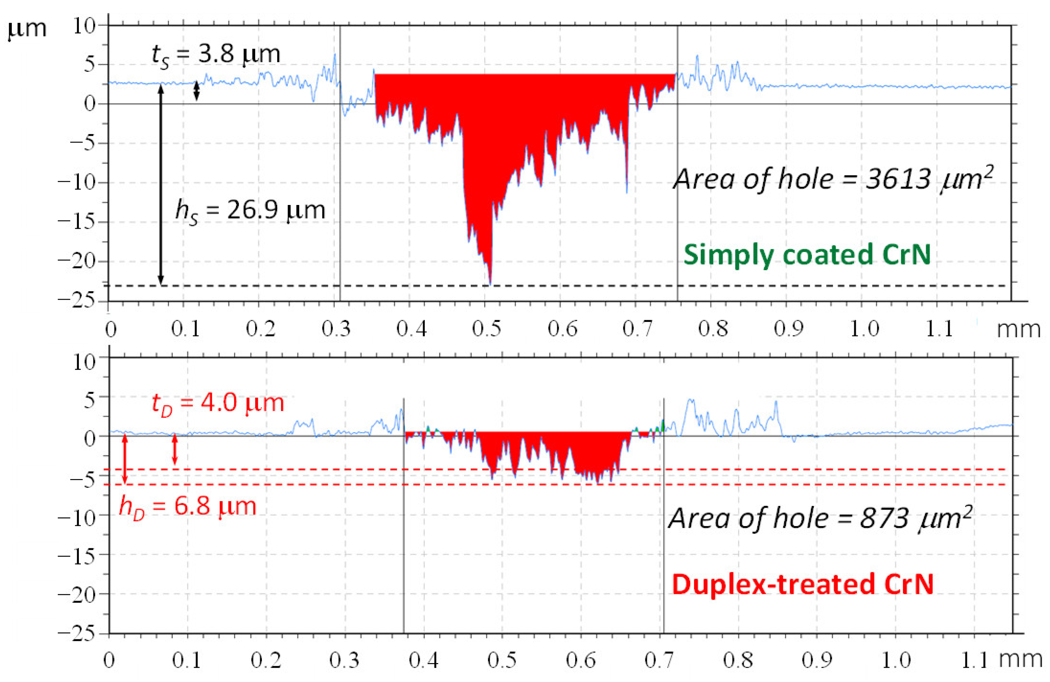
While the optical microscopy of the wear rings showed only a slight difference in the width of the wear tracks of the simply and duplex-treated samples, the profilometry measurements already revealed a significantly higher worn cross section. Consequently, there was a higher amount of material loss for the simply coated sample compared with the duplex-treated one (
Figure 10).
Besides, the ratio of the depth of the wear track (h) to the coating thickness (t) is approximately seven times higher for the simply coated sample, that is, hS/tS = 7.1, while it is hD/tD = 1.7 in the case of the duplex-treated coating system. This finding gives unambiguous evidence of the improvement of the wear resistance of the applied CrN coating deposited on the nitrided steel substrate.
In addition, the profile diagrams reveal that in the case of the simply coated specimen, the coating was entirely removed from the substrate, while the duplex-treated coating remained partially intact in the contact zone.
The specific wear rate values, calculated by Equation (1), were an average of (2.8 ± 0.11) × 10
−5 mm
3/Nm and (1.6 ± 0.76) × 10
−5 mm
3/Nm for the simply coated and duplex-treated samples, respectively. This change represents a 43% reduction in the wear rate due to the duplex treatment, as shown in
Figure 11.
The applied duplex surface treatment resulted in a significant improvement of the wear resistance of the investigated CrN coatings in terms of the reduction of the wear rate.
Formerly, we established that nitriding the substrate preceding the coating deposition does not alter the wear mechanism of the duplex-coated system compared with that of the simply coated one for the investigated loading conditions (
Figure 9). The measured wear rate values, which fall into the same order of magnitude (10
−5), are in harmony with this observation.
Usually, a significant change in the wear rate can be expected if the wear mechanism is modified. Here, the observed reduction of the wear rate cannot be attributed to such kind of phenomenon. The duplex treatment led to the observed favourable wear behaviour by altering the substrate microstructure, improving its loadability, and providing better support for the hard and brittle coating, significantly increasing the composite hardness and the joint performance of the substrate/coating composite system.
Here, it should also be noted that the applied F = 20 N normal load already causes failure of the CrN coating at the very early stage of the wear test. Research works on CrN coating reflect that the applied loading conditions represent a severe loading regime for this tribosystem [
59,
60].
The measured wear rate values, especially those obtained for the duplex-treated sample, fall close to the values of 10−6 mm3/Nm representing the border between the mild and severe wear regimes. The enhancement of the substrate loadability through optimising the duplex treatment—particularly regarding the high-temperature nitriding—would provide a breakthrough to this border, changing the wear regime to mild wear.
Similarly, as mentioned in connection to scratch studies available in the literature, several reports on wear tests for CrN coatings can also be found [
61,
62,
63,
64]. However, the possibility for comparison with the current results is very limited due to the different substrate characteristics and differences in the applied test parameters that play a vital role in the wear mechanisms and wear resistance of the tribosystem.
4. Conclusions
The tribological performance of CrN coatings deposited by the PVD technique on a high Cr content X42Cr13 tool steel was analysed by comparing two different conditions of the substrate/coating system. On the one hand, the coating was deposited by PVD directly to the quenched and highly tempered (secondary-hardened) substrate. On the other hand, duplex treatment, consisting of nitriding and a subsequent CrN coating of the substrate material, was applied. Tribological behaviour was studied in scratch and wear-type loadings. The main findings of the research work can be summarised as follows.
The investigated high Cr content steel represents a key issue regarding the appropriate combination of nitriding parameters during duplex treatment. The applied high-temperature nitriding technology—characteristic of this steel in case of maximum toughness requirements—is less investigated and reported in the literature. The related problems were demonstrated during structural and compositional analyses of the obtained nitrided layer, demonstrating a steep hardness profile, low nitrided case depth, and characteristic high residual stresses due to the intense CrN precipitation. Despite these problems, the applied duplex treatment resulted in a considerable improvement of the tribological performance reflected by the 34% higher critical loads during scratching, that is, higher resistance to coating delamination and a 43% improvement of the wear resistance in terms of the calculated wear rate.
During morphological analyses of the scratch grooves, a new damage mechanism named “SAS-wings” was identified, which is a characteristic of the simple CrN tribosystems and a preliminary indicator of the critical failure of the ceramic coating not observed for the duplex-treated systems.
The research work confirmed that the duplex treatment is an effective and advantageous solution to improve the tribological behaviour of the tested CrN coating by increasing the load-bearing capacity of the applied X42Cr13 steel substrate. It allows for a significant decrease in material loss due to wearing, thereby increasing the lifetime of the tool.
One of the important application areas of X42Cr13 steel is the plastic mould tool industry. Due to dynamic loadings, the lifetime during plastic injection moulding or extrusion is often controlled by the toughness of the tool, and it is limited significantly by the abrasive wear caused by reinforcing particles, such as glass and carbon fibres of the processed plastic materials. The use of duplex technology in the case of high-toughness, low-hardness tool steels is significant because the hard CrN coating, applied for high wear resistance, can lead to a significant hardness gradient occurring at the interface between the substrate and the coating, limiting this way considerably the achievable improvement of the wear resistance. The duplex treatment may essentially reduce this hardness gradient and the accompanying weaker performance.
X42Cr13 steels are often replaced by prehardened steels—e.g., X30Cr13 (DIN) equivalent with SUS420J2 (JIS), AISI 420, or 420S45 (BS)—the heat treatment and the corresponding hardness of which are very similar to those of the tested steel. However, these types of steels are marketed in large blocks; therefore, manufacturing test specimens required for the wear test is rather complex, labour intensive, and expensive. The wear tests performed can also be considered model tests for these steels, and the obtained results can be effectively used for the wear problem solutions of such prehardened steels too.
Another crucial area of utilisation is represented by improving the mould release capability of the plastic forming tools and reducing the tool opening force. Using the CrN coating, the interfacial energy can be significantly reduced; consequently, the tool opening force can be reduced. This green technology solution can take the place of using release agents, which both pollute the environment and contaminate the finished product and the tool.
The presented tribological investigations with the novel combination of constituents applied in the tribosystem open many aspects where a significant study and further research are proposed. These novel findings provide a reasonable basis for future work to elaborate an optimised set of technological parameters for the duplex technology of the given tribosystem. Further improvements in the efficiency of the scratch and wear resistance can be achieved if a more diffused hardness profile with a higher case depth is obtained by the optimised parameters of the high-temperature nitriding.
A new series of wear tests with a decreasing normal load is suggested to determine the threshold of the load-bearing capacity of the investigated tribosystem. Such a programme would also allow for a more thorough examination of the wear resistance by avoiding the premature failure of the CrN coating observed in the current study. Reducing the normal load during the wear test allows for reaching the transition from severe to mild wear regime. This change in wear behaviour may be promoted by elaborating the appropriate high-temperature nitriding technology, less studied, reported, and applied currently, but promising regarding improving the wear resistance of the analysed tribosystem.


