Article

Forming of Additively Manufactured Ceramics by Magnetic Fields

1
Department of Visual Arts, Faculty of Architecture, RWTH Aachen University, Schinkelstr. 1, 52062 Aachen, Germany
2
Institute for Materials Applications in Mechanical Engineering, RWTH Aachen University, Augustinerbach 4, 52062 Aachen, Germany
*
Authors to whom correspondence should be addressed.
Ceramics 2022, 5(4), 947-960; https://doi.org/10.3390/ceramics5040068
Submission received: 30 September 2022 / Revised: 21 October 2022 / Accepted: 28 October 2022 / Published: 3 November 2022
(This article belongs to the Special Issue Advances in Ceramics)

Abstract

:
The application of additive manufacturing using liquid material extrusion is inherently linked to material-related deformations and limitations in the choice of component geometry. This empirical study addresses the question of how the plasticity of a ceramic composite material can be utilized for a new integrated design and manufacturing process. In the exploratory approach, the liquid material is not limited in its soft plastic state, but its malleability is harnessed for a design-oriented approach. For this purpose, soft magnetic particles are added to a liquid clay mass. The developed composite material can be controlled, stabilized, and shaped by magnetic fields directly in the additive manufacturing process using modified equipment. In this study a permanent magnet and an electromagnet were compared while the distance between the printed part and the magnet was controlled by an optical sensor.

Graphical Abstract

1. Introduction

The process of liquid material extrusion, also called liquid deposition modeling (LDM), is currently being investigated in several engineering applications [1,2]. Although LDM is comparatively fast, cost-effective, and versatile [3], material-related shrinkage and inaccuracies in material deposition have to be considered [4] in the initial design. Problematic issues include perforations and material overhangs, which can only be addressed by a high amount of support structures that have to be painstakingly removed afterwards [5]. Current approaches attempt to minimize the complex deformation behavior of liquid masses by utilizing materials that solidify quickly after deposition [6]. Thus, a technically orientated approach is pursued, in which the material deposition follows the highly accurate instructions generated based on digital design. Pérez-Gomez described the influence of the tool or machine on the process and concluded, “tools are never neutral” [7]. The potential for digital fabrication to overcome machine limitations in design processes is recognized and encouraged in various approaches [8]. In this context, hardware, software, and material need to be more interconnected in order to complement each other [8].
Contactless forming using electromagnetic fields is well-known from sheet metal forming. In this process, an inductor generates a pulsating electromagnetic field and changes the shape of the workpiece by means of opposing eddy currents [9]. The forming of ceramic liquids by magnetic fields is not yet known. In fused deposition modeling, the effects of electromagnetic force on thermoplastic materials have already been demonstrated [10]. The “magnetic force control device” developed for this purpose deforms the heated thermoplastic material via planar “arranged 3 × 3 actuators”. As the material cools and solidifies in the shape defined by the magnetic field. In a similar way, electromagnetic fields at the nozzle outlet of a filament extruder are also used to align soft and hard magnetic particles in the plastic filament and thus produce cost-effective complex-shaped permanent magnets [11].
The electromagnetic forming of ceramic liquids becomes possible when soft magnetic particles are integrated. This fundamentally changes the material properties. Today, ceramics and metals are combined in industrial engineering to form composites with advantageous thermophysical and mechanical properties. Ceramic-particle-reinforced MMCs (metal matrix composites) or metal–ceramic composites with percolating structures are well-established. For this purpose, ceramic particles are, for example, alloyed into steels (e.g., ODS steels) to increase strength or wear resistance, or open-porous ceramics are pressure-infiltrated with copper, for example, to increase the fracture toughness and thermal conductivity of the monolithic ceramic. MMCs can also be produced by molding plastic masses and sintering. In the field of CMCs (ceramic matrix composites), ceramic fibers are incorporated into plastics or a ceramic matrix itself to achieve, for example, higher fracture elongation and crack resistance or thermal shock resistance for space, energy, and lightweight applications. Integrating ductile metal particles into a ceramic matrix can increase crack toughness by bridging cracks [12]. Depending on the thermal expansion coefficient, microresidual stresses can be exploited for crack deflection. Despite this, metal-particle-reinforced CMCs are still considered scientific curiosities rather than established engineering materials [13]. Ductile iron particles in an Al2O3 matrix have been investigated with different particle sizes and distributions as well as fabrication methods in terms of thermal shock resistance and residual strength or cracking behavior [14,15,16,17]. The typical sintering atmosphere is argon to avoid the (partial) oxidation of the metallic particles.
The aim of the present study was to compare the basic types and arrangements of magnets and the resulting ability to deform a green body in a controlled manner. Consequently, a composite material with a sufficient amount of metal particles must be developed to enable electromagnetic forming. At the same time, however, the proportion of metal particles must be low enough to avoid the high residual stresses and damage induced by the high thermal expansion of the added particles. In addition to pure iron particles, soft magnetic particles made of martensitic and ferritic corrosion-resistant steel were also tested. In order to produce cost-effective composites in the future, sintering should take place in air atmosphere. Two case studies were conducted to investigate how the still-soft composite material could be reshaped during or immediately after the printing process into a new geometry that deviates from the printing parameters. The magnetic fields required for deformation were created either by an electromagnet at a fixed position (case study 1) or by a movable permanent magnet (case study 2). To avoid the collision of the permanent magnet and printed part, the distance between the printed part and the magnet was monitored by an optical sensor.The described exploratory approach aims to investigate the design potential of liquid masses for an integrated, design-oriented approach and to unlock and harness the malleability of the material postdeposition as part of the design and manufacturing process.

2. Materials and Methods

This study was based on the following assumptions: (1) The developed composite material has deformation, drying, and sintering behaviors similar to pure clay bodies, whose behaviors in LDM have been described in previous publications [18]. (2) The additive build-up process of clay bodies by the LDM system, Delta WASP2040 Clay Printer, through G-code instructions is well-known. (3) The investigation on the control of the liquid composite material and its molding behavior was carried out using a self-developed autonomous add-on module made for the dimensions of the Delta WASP2040 Clay Printer. (4) A digital model in the form of a wall was adopted for the comparability of the test results. The wall produced in the LDM was only conditionally stable without a support structure.

2.1. Composite Material

The liquid material was created by adding ferromagnetic steel particles to kaolinitic clay powder (see Table 1), homogenizing the blend with a roller mixer, and adding water.
To prevent high frictional forces from affecting the nozzle during the printing process, fine, spherical steel particles were employed. To minimize corrosion in the water-based mixture at a pH of 7.1 and the high-temperature oxidation during sintering, the steel needed to form an external protective chromia layer. This demanded high chromium contents. In addition, a soft magnetic material that aligned with the external magnetic field was required. In this study, AISI 430L special atomized ferritic steel powder was available for preliminary material development tests. For the compression tests, AISI 630 martensitic steel, which is commercially available, was used. For comparison purposes, another mass was prepared using pure iron powder. Table 2 summarizes the chemical compositions, particle sizes, and shapes of the powders used.
After air drying, green bodies were sintered with the typical sintering profile of clay (100 K/h to 600 °C, 300 K/h to 1200 °C (2 h), and 300 K/h to RT). Samples were embedded in epoxy resin, prepared, and examined under an optical microscope (Axiophot, Zeiss, Jena, Germany) and a scanning electron microscope (LSM 6400, Jeol, Freising, Germany) to evaluate particle attachment after cosintering and different standing times of the liquid mass. Possible reactions between steel and clay were observed during sintering in a differential scanning calorimeter (DSC 404, Netzsch, Selb, Germany) with increasing contents of AISI 630 particles. The flexural strength of the CMC composite was determined by a four-point bending test according to EN 843-1. All bending bars were printed with a fixed composition of 17.5 wt.% AISI 430L steel particles, 52.5 wt.% clay powder, and 30 wt.% water. The expansion behavior of such a bending bar during heating and sintering was investigated in a dilatometer (DIL 402C, Netzsch, Selb Germany).

2.2. LDM System

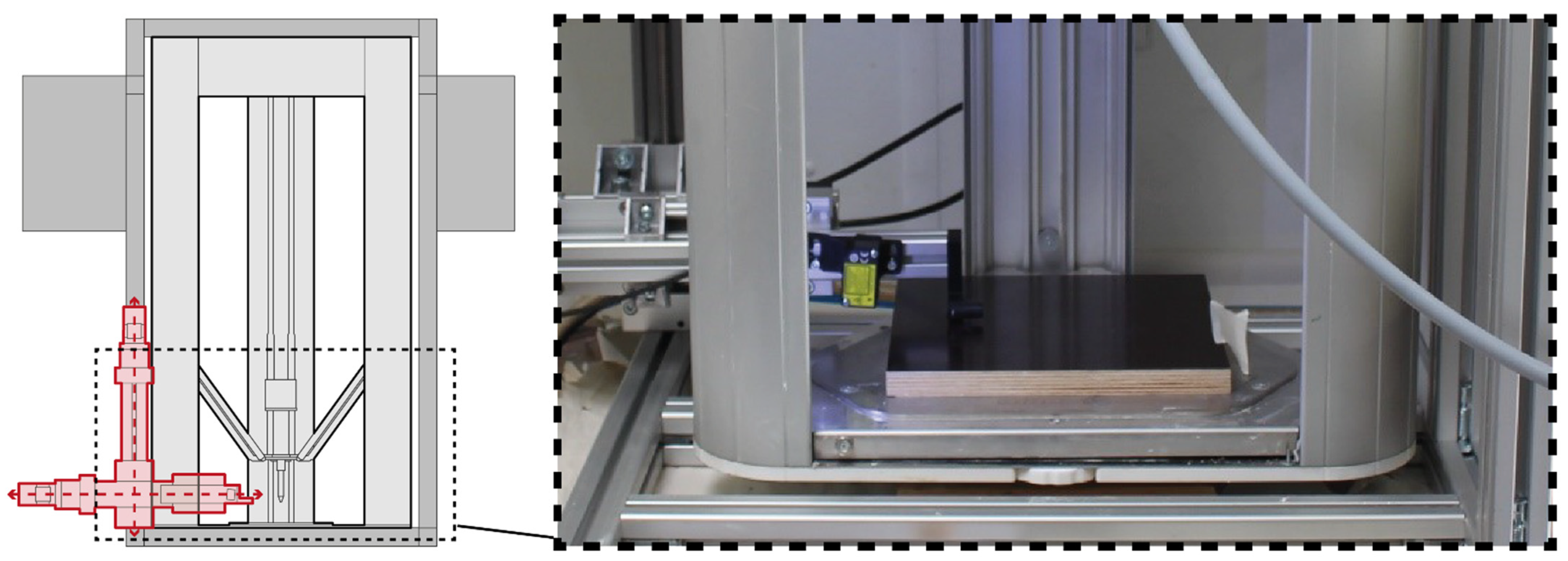
The clay printer used for the experiments corresponded to the configuration of a Delta printer with three double support rods moving in space, each driven by a vertical belt. An extruder with a material feed tube was mounted on a horizontal carriage supported by the rods. The liquid material used for the additive build process was supplied by an external cartridge using compressed air. The maximum print volume of the clay printer was a cylindrical shape with the measurements of d = 200 mm and h = 400 mm. To avoid collisions of the components with the additive module, a 50 mm-long extended nozzle with a circular outlet with d = 1 mm was designed for the Delta Clay Printer, which was manufactured by fused deposition modeling in nylon.

2.3. Additional module

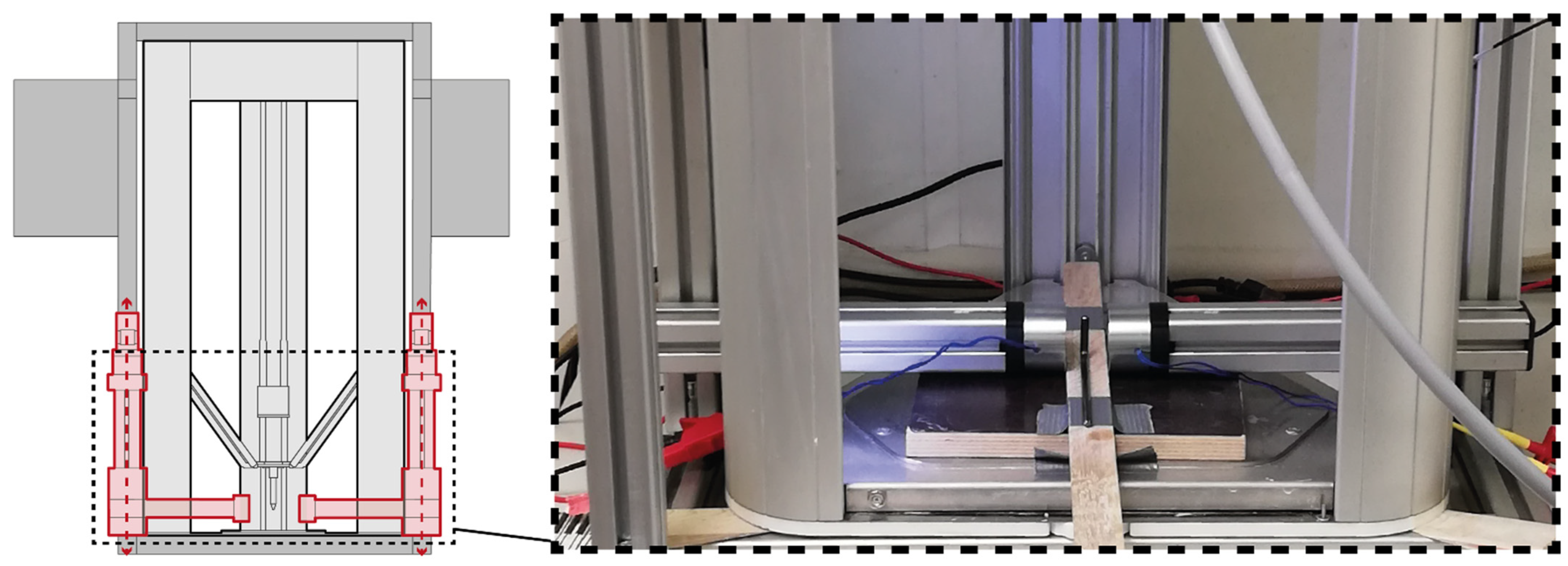
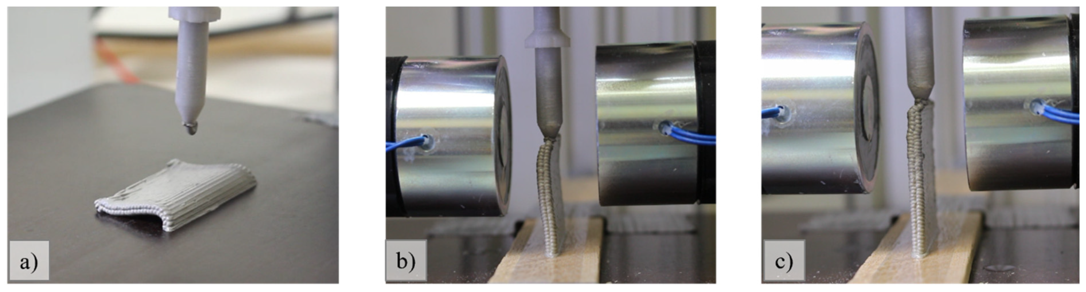
The additional module by Zumolab GmbH was built around the LDM system using a frame structure made of aluminum profiles (
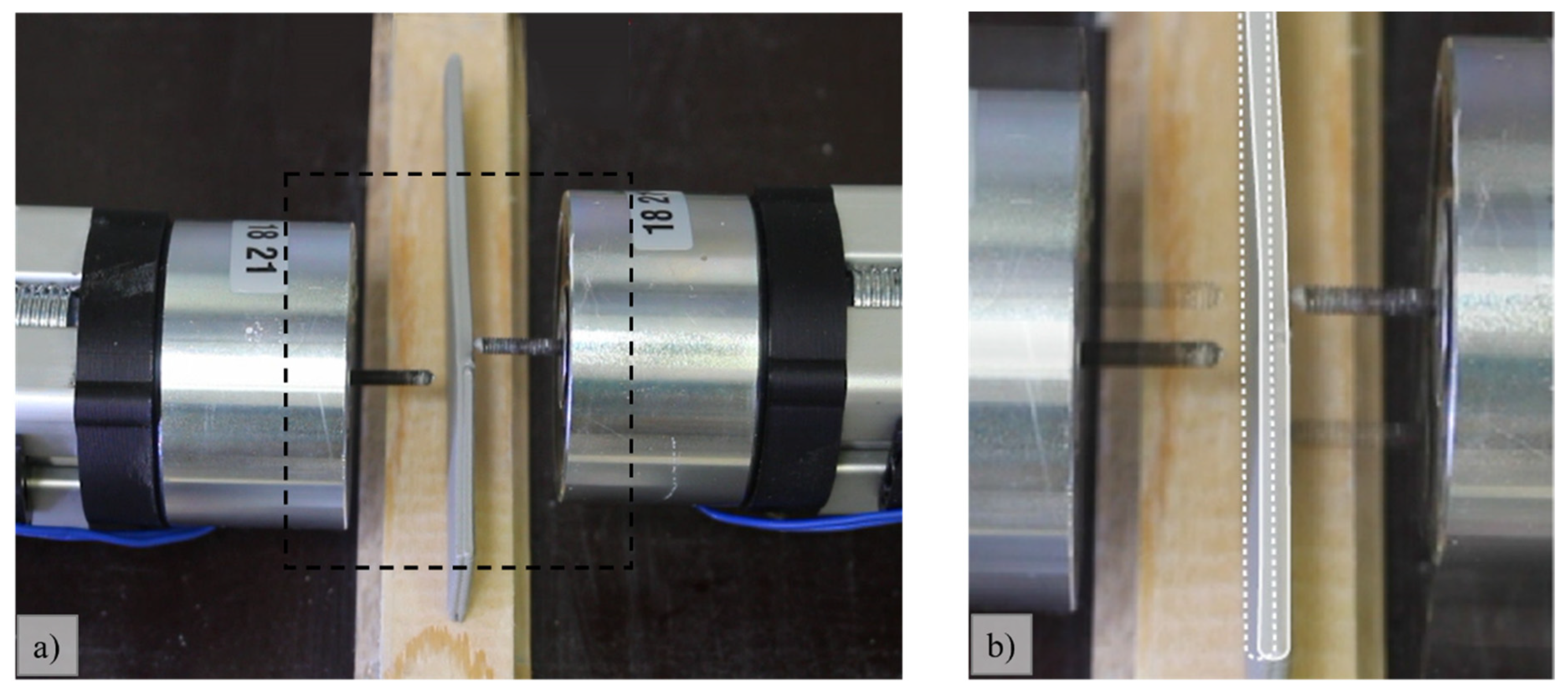
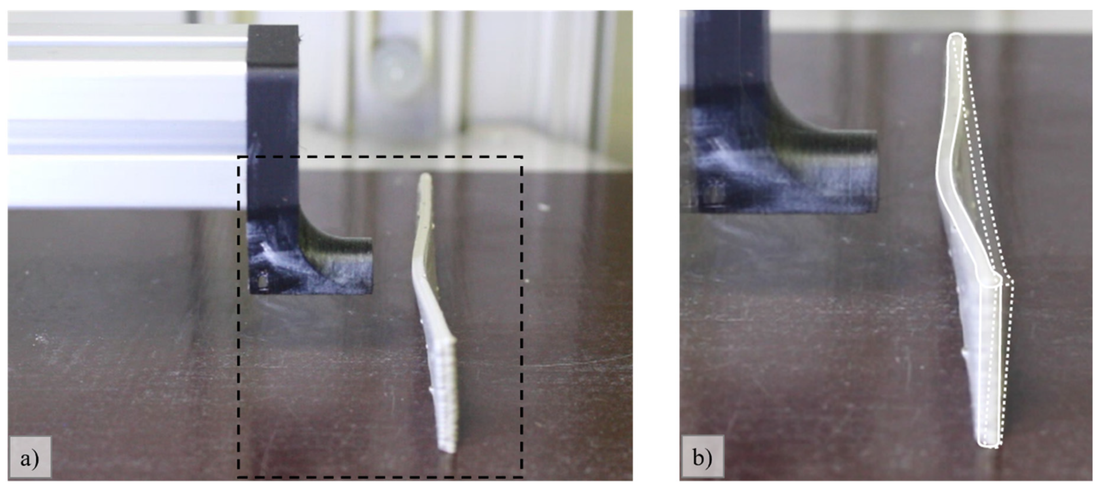
Figure 1). The additional module was autonomous and consisted of two components: motor control and a U remote for the collection of analog measurement data. The individual components were connected in a network and could be operated via controlling software. Two opposing vertically positioned linear travel units carried the magnets. In case study 4.1, electromagnets were applied. In case study 4.2, a permanent magnet with a modification of the linear travel units in the horizontal axis and a laser sensor were added.

2.4. Digital Model

The instructions for the print job were generated using the visual programming environment Grasshopper. This program allows the generation of detailed specifications of path geometry, print direction, build-up speed, layer height, and extrusion rate as well as conversion to G-code (see Table 3). The 3D printing parameters and path instructions influence the printing result. In preliminary tests, it was possible to develop a wall system that achieved a consistently stable print height of ~30 mm (Figure 2c). This value was adopted for all further tests as a reference for the maximum print height and stability of the wall system without external manipulation.

3. Material Engineering

Processing a liquid CMC mass by LMD extrusion requires constant rheological properties. In particular, the time- and pH-dependent reaction of iron to form iron hydroxide around the steel particles in the liquid mass or drying green body can be critical. Figure 3a shows how this corrosive attack led to high porosity in the air-sintered composite when particles of pure iron were used. The former iron hydroxide was converted to iron oxide fringes during sintering, and metallic bright iron was very rarely visible. If the 430L steel particles with a chromium content of 17 wt.% were used, the Cr2O3 passivation layer was effectively able to prevent the formation of hydroxides. The micrograph shows brightly shining metallic particles surrounded by a very fine seam (Figure 3b). The seam thickness was unchanged when the mass was processed after 3 days and subsequently sintered.
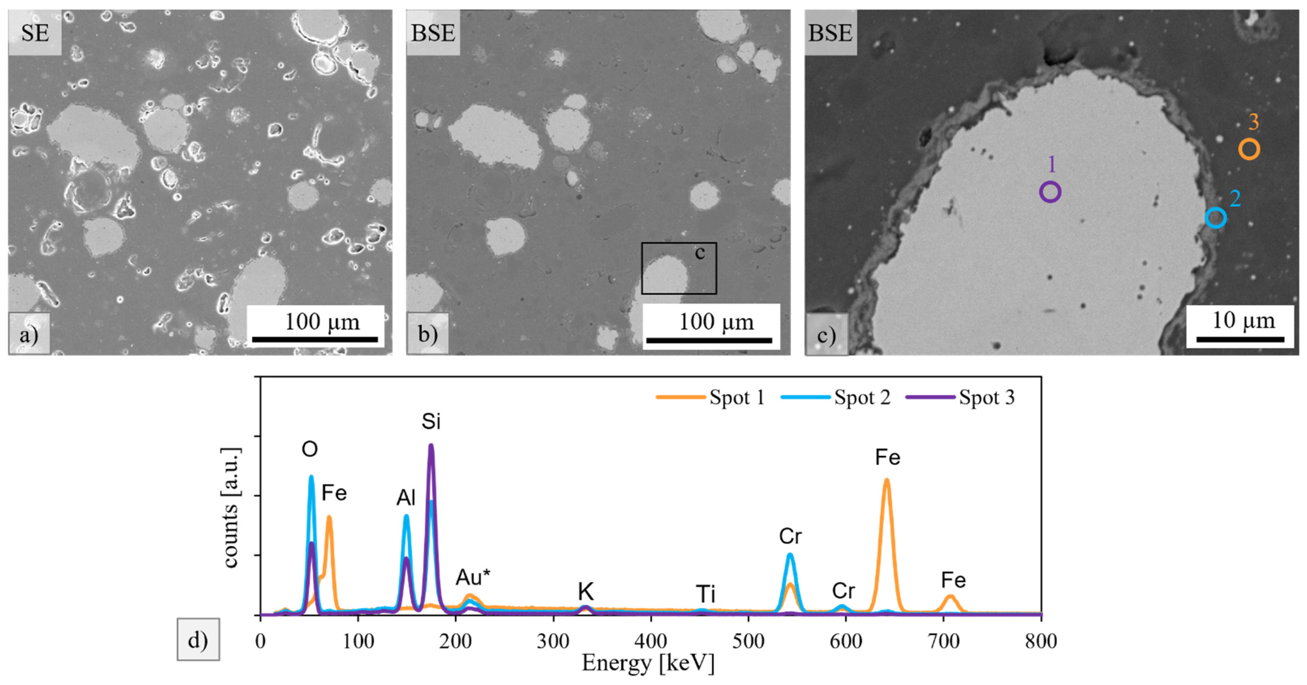
In the scanning electron micrograph of the sample that was dried and sintered after 3 days, some pores were visible in the secondary electron contrast (Figure 4a). However, these were predominantly found in the clay matrix and did not affect particle attachment. In the backscattered electron contrast (Figure 4b and especially in the enlarged detail in Figure 4c), the sharply defined seam around the steel particles was very clear. The EDS point analyses (Figure 4d) revealed pure metallic iron–chromium steel at spot 1, an Al-Si-Cr oxide in the seam (spot 2) and in the clay matrix as Si-Al oxide with traces of K, Ti, Fe, and Cr.
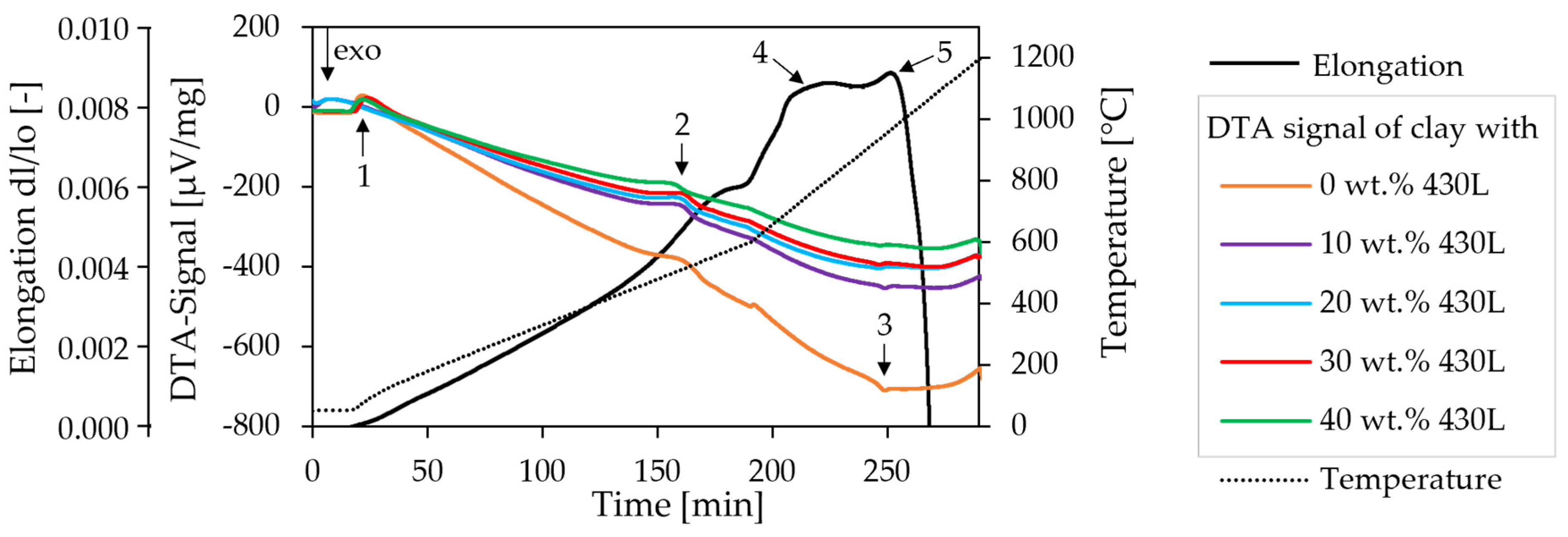
Figure 5 shows the changes in exothermic or endothermic reactions with increasing weights of steel particles. It should be noted that no background correction was made, and thus only the upward (endothermic) and downward (exothermic) deviations from the smooth curve are to be evaluated. The addition of steel particles did not introduce new peaks, which confirms that no relevant reactions between steel and clay occurred. After the evaporation of the water (peak 1), dehydration occurred at about 500 °C (peak 2) [19]. The small exothermic reaction (peak 3) probably corresponded to the formation of gamma-Al2O3 in kaolinite [19]. The green body expanded due to thermal lattice expansion until the curve flattened at 800 °C (peak 4), marking the beginning of sintering activity. At 1000 °C, the composite material shrank very quickly (peak 5) by a total of 6.7% until the beginning of the isothermal holding phase.
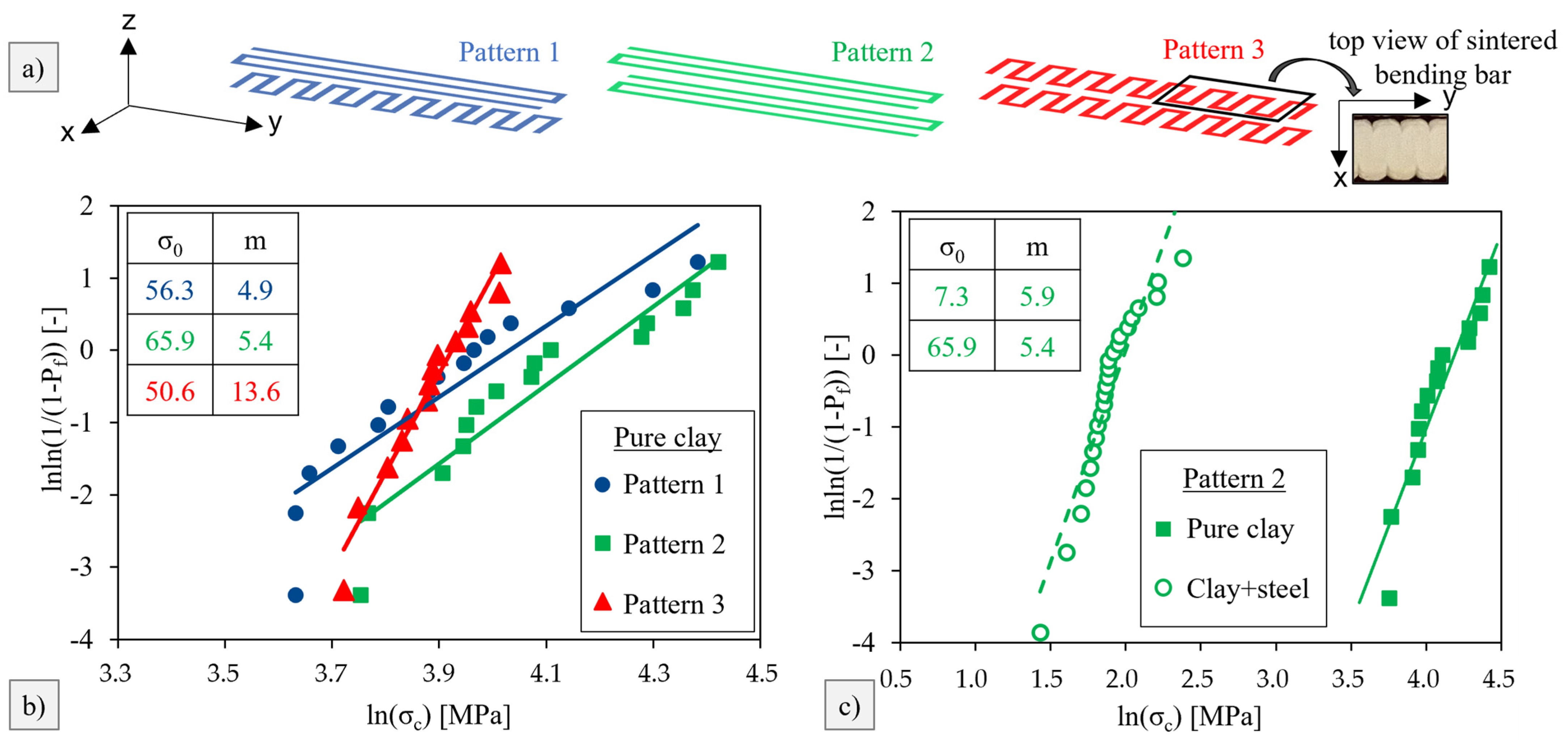
Sintered composite bars, approximately 4.3 × 4.3 × 48 mm3 in size, were tested by means of the standardized four-point bending test in accordance with EN 843-1. In order to investigate the influence of a possible notch effect, due to different pressure layouts, on the strength, the three different print patterns in Figure 6a were tested. The determined fracture forces were converted into fracture stresses, as described in EN 843-5, and a fracture probability, Pf, was assigned to each specimen. In the Weibull diagram of Figure 6b and c, data points on the right indicate high strength. The slope, m, of the regression line describes the scatter of the strength by the Weibull modulus. The higher the Weibull modulus, m, the lower the strength scatter. At a fracture probability of 63%, the ordinate value becomes 0, and the associated strength is called the characteristic strength, σ0. Printing pure clay in pattern 3 resulted in a poor characteristic strength of 50.6 MPa. However, the corresponding Weibull modulus of 13.6 was high, indicating that the stress concentration always initiated failure of the same defect type. With pattern 2, the characteristic strength was increased since notches were removed. Pattern 1 was exactly between patterns 2 and 3 in terms of the Weibull modulus and characteristic strength, as the layered structure also suggested. Pattern 2 was selected as the print layout for the composite bars. As depicted in Figure 6c, the strength of the composite material was comparably low. Despite the optically good particle bonding within the clay matrix, the characteristic strength was reduced significantly from 66 MPa to 7 MPa by the addition of steel particles. Increased toughness due to the addition of ductile particles could not be proven. Future investigations will have to clarify if the martensitic transformation of the AISI 630 leads to nonbeneficial microresidual stresses or damage.

4. Case Studies

4.1. Case Study with Electromagnets

Two electromagnets (holding force: 40 kg, Ø: 50 mm, thickness: 30 mm, and weight: 350 g) were implemented for Study 4.1 (Figure 7). The electromagnets were each fixed to the vertical linear travel units on horizontally mounted aluminum profiles, extending into the print area. The vertical position of the electromagnets and the holding force of the electromagnets could be controlled independently of each other. Since the horizontal axes for extending the electromagnets were not electrically adjustable, they were manually positioned before the start of the experiment.
As found in the preliminary tests, a wall of ~2 mm material thickness and 50 mm length could be printed stably up to a height of ~30 mm before collapsing (Figure 8a). Figure 8b shows the influence of an electromagnet activated unilaterally and positioned 10 mm away from the wall’s print build-up. Although the wall was also stabilized by the nozzle in the printing process, the tilting of the wall was achieved well before the reference value of ~30 mm print height in the direction of the activated magnet (left). With bilaterally activated electromagnets vertically following the additive build-up of the wall, the build-up height of a wall could be increased to 42 mm (Figure 8c). However, a correlation between the heat radiation of the electromagnets and an associated accelerated drying of the material could not be ruled out and would have to be verified in further experiments.
In a test setup of a wall with ~2 mm material thickness, a 10 mm length, and a print height of 30 mm, the nozzle was raised, and the electromagnets were positioned bilaterally at 6 mm from the wall structure. This allowed for the controlled tilting of the wall (to the left and right) without the additional influence of the nozzle tip (Figure 9a,b). The allowable deviation of the wall from its initial vertical position was less than 5° in order for the opposing electromagnet to be able to pull it back. The influence of the inherent stability of the system wall with the described material properties of clay bodies favored the control. If a deviation of more than ~5° was exceeded in this setup, the wall collapsed (Figure 9c).
In a further setup, the influence of the distance between the electromagnets and the wall structure was tested. First, the unavoidable heat emission of the electromagnets and its effect on the drying of the material was to be reduced. Second, the electromagnetic field was to be further focused to a controllable range. To achieve this, the iron core was drilled out, and a threaded iron rod was inserted, which extended the iron core of the electromagnet by 15 mm. The experiments showed there was an attraction force applied to the wall of ~2 mm material thickness, 10 mm length, and 30 mm height. However, by extending the iron core, no significant gain in the distance from the printed wall to the electromagnet could be achieved. Only by positioning the threaded iron rod at a distance of less than 5 mm from the wall could deformation be achieved (Figure 10). It can be assumed that a broader electromagnetic field exerted a higher impact on the printed wall than the very narrow, focused force at the tip of the threaded iron rod.

4.2. Case Study with Permanent Magnet, Linear Travel Unit in Horizontal Axis, and Laser Sensor

For the study with a permanent magnet, the additional module for forming the material had to be modified. By repositioning one of the vertical linear travel units in the horizontal plane onto the second vertical linear travel units, both the vertical and horizontal positions of the permanent magnet could be controlled electrically. This enabled control over the attraction force of the magnetic field applied to the test wall. A bracket for the aluminum profile held the bar magnet (holding force: 4.4 kg, Ø: 10 mm, height: 20 mm, and weight: 12 g) (Figure 11).
It was found that, across an air gap, the permanent magnet had a much greater effect on the deformation of the material than the previously tested electromagnet. Initially, the distance was manually controlled and tested by holding for several minutes with a distance to the wall of 20 mm–10 mm to see how the deformation of the material could be produced without tilting the overall structure. Then, the permanent magnet was set into a pulsating motion with 12 mm to the wall structure (~2 mm material thickness, 10 mm length, and 30 mm height) (Figure 12). This was to test how a pulsating motion would deform the plastic material, as opposed to holding the magnet for several minutes at a greater distance. Both methods resulted in visible deformation. Since the controllability of the test specimen depended to a large extent on a more precise measuring technique, a laser sensor was subsequently added to the experimental setup.
The laser sensor was fixed 75 mm behind the front of the permanent magnet and was aligned horizontally to the wall. The magnet bracket was adapted so that it could be coaxial with the laser sensor. A decreasing distance to the wall and the concurrent decrease in the focus area of the laser led to an increase of the scan precision. The recorded measurement results from the wall deformation, as determined by the sensor (red) and the absolute magnet position (blue), are shown in Figure 13. The first graph in Figure 13a shows a collapse between the wall and the magnet, which was announced by a progressively increasing wall deformation. The time span between the first detected deformations and the collapse indicates the possibility for further deformation control options. Future investigations must define reproducible threshold values with associated retraction criteria for the permanent magnet to avoid a collapse. The desired slow, controlled deformation has been achieved, for example, in Figure 13b. After the magnet moved to the 88 mm position for the first time, the deformation velocity decayed from the initial 10 µm/s. Moving the magnet back to the 85 mm position allowed a slight relaxation of the deformation. After moving back to the 88 mm position, a deformation that clearly exceeded the former maximum with the desired degressive increase was observed. The wall attraction signal scattered due to surface roughness but also showed some jumps. We suppose that these jumps were directly linked to the surface grooves of the additive structure with depths of at least 0.1 mm. For clarity, different areas are marked in graph 13b, indicating a—approach, r—relaxation, and * for superposition with groove scattering.
In addition, the experiments in Figure 14b,c (wall with ~2 mm material thickness, 10 mm length, and 15 mm height) demonstrated a deformation of the wall’s top edge up to 3 mm from the initial position by holding, briefly approaching, and retracting to 7 mm from the wall.

5. Discussion

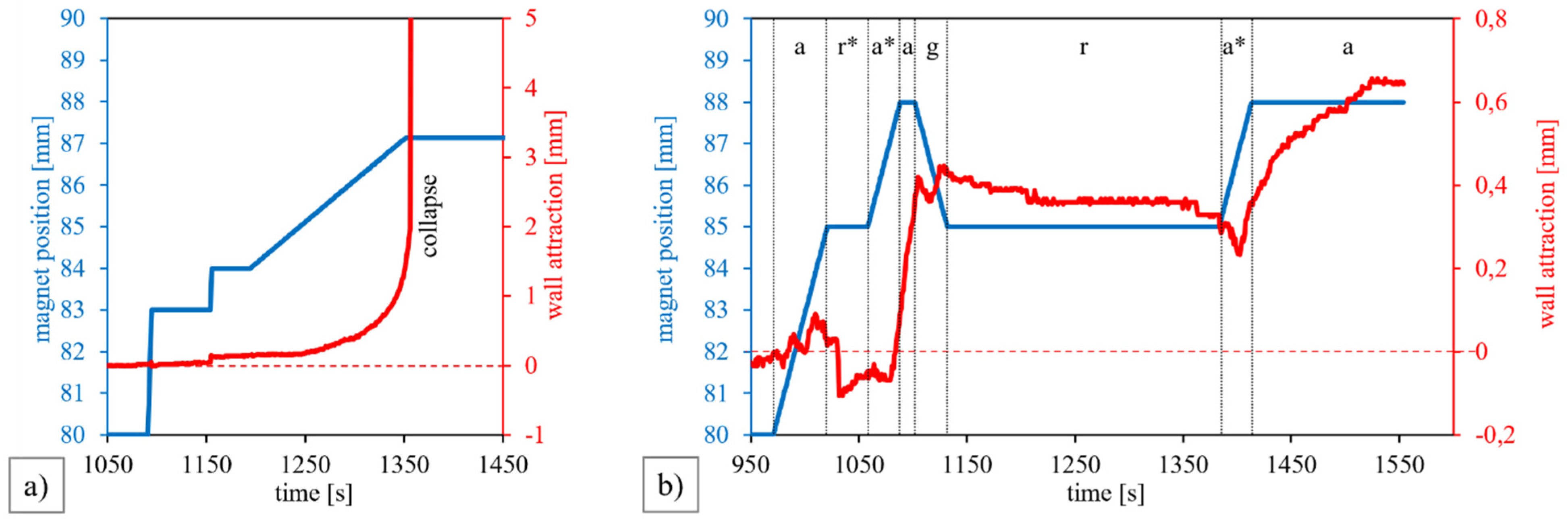
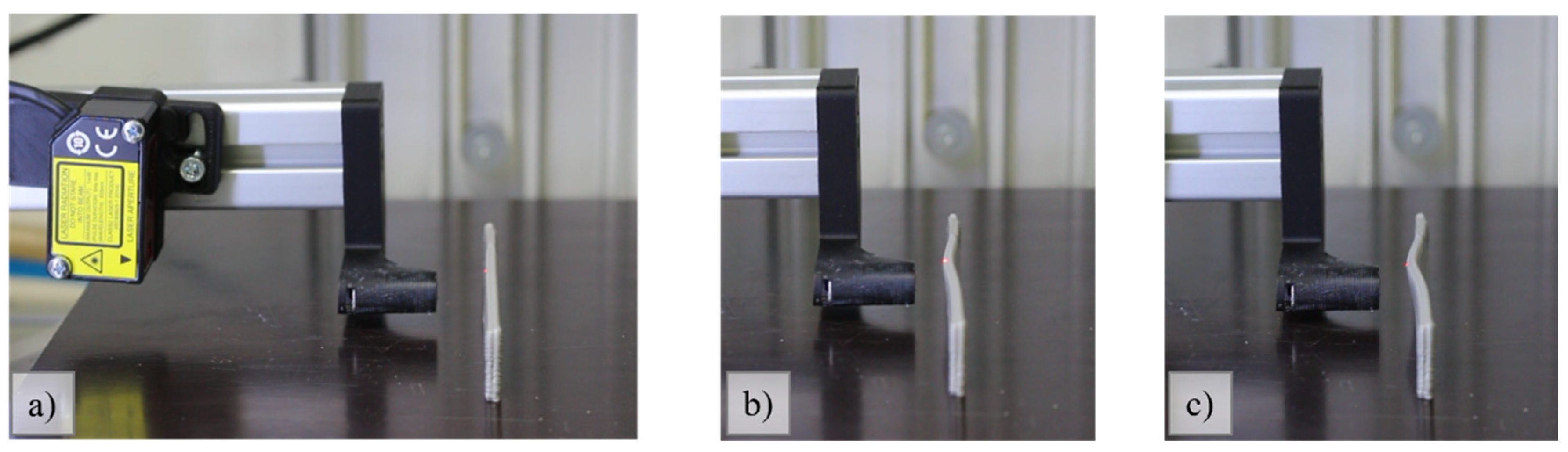
This study demonstrated that the electromagnetic forming of additively manufactured clay bodies is possible using the developed composite material. For technical applications, the comparably low fracture strength needs to be further increased. However, a clear effect of the print pattern on the strength of pure clay was observed, thus indicating promising approaches for improvements in the strength of the composite. If the inner notches of an LDM-processed material can be reduced by electromagnetic forming, the strength will be increased. For this approach, electromagnets would have to increase the connection of the extruded beads directly after depositing on the green component. Furthermore, sintering under atmospheres with lower or significantly lower oxygen contents than that of air will presumably also increase the strength.
A stabilizing effect of electromagnetic fields on the selected printing geometry could be observed since significantly higher walls were printed. The influence of the heat radiation of the electromagnets and the associated drying effects on the material could not be ruled out without further experiments. Although, in principle, an electromagnet promises better control of the deformation behavior due to the controllable magnetic field, this could not be confirmed in the present study. In the case of the selected electromagnet, despite a 10-fold higher holding force, this was due to the unfavorable, nonfocused course of the field lines, which ran predominantly in a radial direction between the iron core and the shell surface. As a result, the field decayed too quickly at a greater distance. The different magnitudes of the magnetic fields of the permanent magnet and electromagnet are clearly visualized in Figure S1 at a distance of about 1 mm. A valid statement about the omission of supporting material could not be further proven within the scope of this study. No visible changes could be observed on the surface of the additively manufactured wall due to the magnetic influence. The processes of the fatigue or saturation of the magnetizability of the liquid material affected control but were not detectable. In the future, it should be investigated whether the liquid composite material can be stabilized in the printing process until the onset of drying so that the need for support structures can be eliminated. Precise measurement and control technology is required for the accurate stabilization or forming of the material, and this needs to be further developed.
The digital design environment currently provides insufficient tools to adequately control a material’s parameters in relation to its physical properties and behavior during the build-up process. This raises the question of which design information must be retained in the digital model for the printing process and which forming parameters can be outsourced to the physical environment by controlling the additional module for electromagnetic deformation. Currently, the state of the physical rendering of digital designs through machine production proves to be an axiomatically simplified set of instructions for action that is not designed to control the production process, the material, and its complex behavior during assembly. The approach explored here was intended to broaden the range of possibilities for liquid material extrusion and make it useful for application in the design and technical fields. This study shows a perspective for a new field of additive manufacturing and for significant influence on classical LDM processes as well as metal-particle-reinforced ceramics in the fields of industrial development.

6. Conclusions

  • The integration of corrosion-resistant steel particles into a liquid clay mass enabled the controlled deformation of printed walls by magnetic fields.
  • Despite the almost 10-fold higher holding force of the electromagnet (40 kg) in comparison to the permanent magnet (4.4 kg), the focus of the magnetic field on the printed wall could not be improved. To stop the attractive force of the permanent magnet on the wall, a linear travel unit was successfully integrated into the equipment.
  • The forming of additively manufactured labile structures in ceramics by magnetic fields bears the risk of a collapse between the magnet and the printed object. To control the distance, an optical sensor was integrated. Progressively increasing distances announced a possible collapse and were interpreted as a signal for permanent magnet retraction.
  • A good deformation strategy was found by combining several phases of approach and retraction of the permanent magnet to allow for a relaxation of the liquid material.
  • The corrosion of steel particles in the liquid was limited by a chromium content above 15 wt.%. No difference in the thickness of the formed chromia scale was observed after 3 days, as demonstrated by microsections of the sintered composite.
  • The sintering of the composite material could be carried out in the same way that pure clay and crack-free bending bars were obtained. No additional reactions between steel and clay were observed until the steel particles in the liquid mass reached a content of 40 wt.%.
  • The determined four-point bending strength of 7 MPa represented a significant decreased in strength after the integration of steel particles. The corresponding strength of the pure clay amounted to 66 MPa.
  • The printing pattern influenced the achieved strength, as demonstrated with pure sintered clay.

Supplementary Materials

The following supporting information can be downloaded at: https://www.mdpi.com/article/10.3390/ceramics5040068/s1, Figure S1: The influence of the magnetic field generated by the electromagnets (a–c) and permanent magnet (d) on iron powder: (a) small electromagnet (12 V, d = 20 mm, 20 N holding force, not used in the main study), (b) electromagnet (12 V, d = 50 mm), (c) electromagnet with iron thread, (d) permanent magnet; Video S1: Clip of Figure 2a—Preliminary tests for the selection of the digital model: (a) straight wall with a 1 mm material thickness; Video S2: Clip of Figure 2b—Preliminary tests for the selection of the digital model: (b) curved wall with a 1 mm material thickness; Video S3: Clip of Figure 2c—Preliminary tests for the selection of the digital model: (c) straight wall with about a 2 mm material thickness; Video S4: Clip of Figure 8b—Influence of electromagnets on test wall: (b) electromagnet activated unilaterally (left); Video S5: Clip of Figure 8c—Influence of electromagnets on test wall: (c) electromagnets activated bilaterally; Video S6: Clip of Figure 9a,b—Wall tilting: (a) starting position, (b) tilting the wall to the left; Video S7: Clip of Figure 10—Illustration of the wall deforming under the influence of the threaded iron rod in the electromagnet; Video S8: Clip of Figure 12—Deformation of the wall by a permanent magnet and pulsating movement (without laser sensor); Video S9: Clip of Figure 14—Deformation of the wall measured with a laser sensor: (a) starting position 12 mm away from the wall; (b) slow approach to 8 mm and stop in front of the wall; (c) short jump to 7 mm and pull back to 8mm.

Author Contributions

Conceptualization, C.K. and S.H.; methodology, C.K. and S.H.; software, C.K. and S.H.; formal analysis, C.K. and S.H.; investigation, C.K. and S.H.; resources, T.H.S. and C.B.; data curation, C.K. and S.H.; writing—original draft preparation, C.K. and S.H.; writing—review and editing, A.K. and T.H.S.; visualization, C.K. and S.H.; supervision, A.K., T.H.S., and C.B.; project administration, C.K. and S.H.; funding acquisition, C.K., S.H., A.K., T.H.S., and C.B. All authors have read and agreed to the published version of the manuscript.

Funding

This work was funded by the Federal Ministry of Education and Research (BMBF) and the Ministry of Culture and Science of the German State of North Rhine-Westphalia (MKW) under the Excellence Strategy of the Federal Government and the Länder under the grant number EXS-SF- OPSF647.

Institutional Review Board Statement

Not applicable.

Informed Consent Statement

Not applicable.

Data Availability Statement

The data presented in this study are available in this article and the Supplementary Materials.

Acknowledgments

Stephan Genilke is thanked for the DTA measurements and the valuable discussions on the construction of the magnet controller. Further thanks go to Vesela Tabakova and Alexander Landschek for their support for the experiments, video recording, and image design.

Conflicts of Interest

The authors declare no conflict of interest.

References

  1. Delgado Camacho, D.; Clayton, P.; O′Brien, W.J.; Seepersad, C.; Juenger, M.; Ferron, R.; Salamone, S. Applications of additive manufacturing in the construction industry–A forward-looking review. Autom. Constr. 2018, 89, 110–119. [Google Scholar] [CrossRef]
  2. Jang, S.; Park, S.; Bae, C. Development of ceramic additive manufacturing: Process and materials technology. Biomed. Eng. Lett. 2020, 10, 493–503. [Google Scholar] [CrossRef] [PubMed]
  3. Farahbakhsh, M.; Rybkowski, Z.K.; Zakira, U.; Kalantar, N.; Onifade, I. Impact of robotic 3D printing process parameters on interlayer bond strength. Autom. Constr. 2022, 142, 104478. [Google Scholar] [CrossRef]
  4. Li, W.; Armani, A.; Leu, M.C.; Landers, R. Methods of Extrusion-On-Demand for High Solids Loading Ceramic Paste in Freeform Extrusion Fabrication. In Proceedings of the Solid Free-form Fabrication Symposium, Austin, TX, USA, 10–12 August 2015. [Google Scholar]
  5. Gürsoy, B. From Control to Uncertainty in 3D Printing with Clay. In Proceedings of the 36th International Conference on Education and Research in Computer Aided Architectural Design in Europe, Computing for a better tomorrow, Łódź, Poland, 19–21 September 2018; Kępczyńska-Walczak, A., Białkowski, S., Eds.; eCAADe: Brussels, Belgium, 2018; Volume 2, pp. 21–30. [Google Scholar]
  6. Revelo, C.; Colorado, H. 3D printing of kaolinite clay with small additions of lime, fly ash and talc ceramic powders. PAC 2019, 13, 287–299. [Google Scholar] [CrossRef]
  7. Ayres, P. Persistent Modelling: Extending the Role of Architectural Representation; Routledge: Abingdon, UK, 2012; ISBN 9780203782545. [Google Scholar]
  8. Nan, C.; Patterson, C.; Pedreschi, R. Digital Materialization: Additive and Robotical Manufacturing with Clay and Silicone. In Proceedings of the 34th International Conference on Education and Research in Computer Aided Architectural Design in Europe. Complexity & Simplicity, Oulu, Finland, 24–26 August 2016; Herneoja, A., Österlund, T., Markkanen, P., Eds.; eCAADe: Brussels, Belgium, 2016; Volume 1, pp. 345–354. [Google Scholar]
  9. Linnemann, M.; Scheffler, C.; Kurka, P.; Psyk, V.; Landgrebe, D. Inkrementelle elektromagnetische Umformung. ZWF 2017, 112, 454–458. [Google Scholar] [CrossRef]
  10. Yamaoka, J. Rapid and Shape-Changing Digital Fabrication Using Magnetic Thermoplastic Material. In Proceedings of the SIGGRAPH ′20: Special Interest Group on Computer Graphics and Interactive Techniques Conference, Virtual Event USA, 17 August 2020; ACM: New York, NY, USA, 2020; pp. 1–2, ISBN 9781450379731. [Google Scholar]
  11. Chaudhary, V.; Mantri, S.A.; Ramanujan, R.V.; Banerjee, R. Additive manufacturing of magnetic materials. Prog. Mater. Sci. 2020, 114, 100688. [Google Scholar] [CrossRef]
  12. Konopka, K.; Maj, M.; Kurzydłowski, K.J. Studies of the effect of metal particles on the fracture toughness of ceramic matrix composites. Mater. Charact. 2003, 51, 335–340. [Google Scholar] [CrossRef]
  13. Yeomans, J.A. Ductile particle ceramic matrix composites—Scientific curiosities or engineering materials? J. Eur. Ceram. Soc. 2008, 28, 1543–1550. [Google Scholar] [CrossRef] [Green Version]
  14. Wenzel, C.; Aneziris, C.G. Ceramic matrix composites based on Mg-PSZ with Cr–Ni-steel-additions with improved thermo-mechanical properties. Mater. Sci. Eng. B 2011, 176, 32–40. [Google Scholar] [CrossRef]
  15. Trusty, P.A.; Yeomans, J.A. The toughening of alumina with iron: Effects of iron distribution on fracture toughness. J. Eur. Ceram. Soc. 1997, 17, 495–504. [Google Scholar] [CrossRef]
  16. Aldridge, M.; Yeomans, J. The thermal shock behaviour of ductile particle toughened alumina composites. J. Eur. Ceram. Soc. 1999, 19, 1769–1775. [Google Scholar] [CrossRef]
  17. Guichard, J.L.; Tillement, O.; Mocellin, A. Preparation and characterization of alumina–iron cermets by hot-pressing of nanocomposite powders. J. Mater. Sci. 1997, 32, 4513–4521. [Google Scholar] [CrossRef]
  18. Klug, C.; Schmitz, T.H. Examining the Interactions of Design Parameters in the LDM of Clay as the Basis for New Design Paradigms. Ceramics 2022, 5, 131–147. [Google Scholar] [CrossRef]
  19. Grim, R.E.; Rowland, R.A. Differential thermal analysis of clays and shales, a control and prospecting method. J. Am. Ceram. Soc. 1944, 27, 65–76. [Google Scholar] [CrossRef]
Figure 1. Construction system of the Delta 3D printer with the additional module installed.
Ceramics 05 00068 g001
Figure 2. Preliminary tests for the selection of the digital model: (a) straight wall with a 1 mm material thickness; (b) curved wall with a 1 mm material thickness; (c) straight wall with about a 2 mm material thickness.
Ceramics 05 00068 g002
Figure 3. Light microscopic images of air-sintered composites consisting of clay with (a) iron particles or (b,c) 430L steel particles. Samples were dried and sintered immediately (a,b) or after 3 days (c).
Ceramics 05 00068 g003
Figure 4. (a) Secondary image (SE) and (b) backscattered image (BSE) of a clay sample with 50 wt.% 430 L particle additions that was dried and sintered after 3 days. (c) Detail of figure (b) with marked EDS analysis points. (d) EDS results of spots 1 (steel), 2 (seam), and 3 (clay matrix) marked in (c).
Ceramics 05 00068 g004
Figure 5. Elongation of clay with 25 wt.% AISI 630 particles and enthalpy change of clay with different amounts of 430 L particles during heating to the sintering temperature of 1200 °C. The heating rate of 300 K/h was increased to 600 K/h at 600 °C.
Ceramics 05 00068 g005
Figure 6. (a) Printing patterns 1, 2, and 3 of the different tested groups of bending bars. (b) Weibull plot of pure clay printed in the different printing patterns. (c) Weibull plot of pure clay and clay with 17.5 wt.% AISI 630 particles, both printed in pattern 2.
Ceramics 05 00068 g006
Figure 7. Detail of the structure of the additional module for case study 4.1.
Ceramics 05 00068 g007
Figure 8. Influence of electromagnets on a test wall: (a) without influence (collapse reference value h > ~30mm); (b) with electromagnet activated unilaterally (left); and (c) with electromagnets activated bilaterally.
Ceramics 05 00068 g008
Figure 9. Wall tilting: (a) starting position; (b) tilting the wall to the left; (c) collapsing wall.
Ceramics 05 00068 g009
Figure 10. Illustration of the wall deforming: (a) under the influence of the threaded iron rod in the electromagnet; (b) schematic comparison to the initial position.
Ceramics 05 00068 g010
Figure 11. Detail of the structure of the additional module for case study 4.2.
Ceramics 05 00068 g011
Figure 12. Deformation of the wall: (a) by a permanent magnet and pulsating movement (without laser sensor); (b) schematic comparison to the initial position.
Ceramics 05 00068 g012
Figure 13. Recorded measurement results with laser sensor: (a) stepwise approach of the magnet position until wall collapse; (b) improved wall deformation with decreasing wall attraction velocity and relaxation. a—approach, r—relaxation, * groove scattering.
Ceramics 05 00068 g013
Figure 14. Deformation of the wall, measured with a laser sensor: (a) starting position 12 mm away from the wall; (b) slow approach to 8 mm and stop in front of the wall; (c) short jump to 7 mm and pull back to 8 mm.
Ceramics 05 00068 g014
Table 1. Specifications of the kaolinite clay (Sibelco, Westerwald clay 161): oxide content in wt.% according to the supplier and bulk density as determined by helium pycnometry (Micromeritics AccuPyc 1330).
Composition in wt.% Bulk Density in gcm−3
SiO2TiO2Al2O3Fe2O3CaOMgOK2ONa2O
8.31.425.51.10.42.92.90.22.68
Table 2. Chemical compositions, sizes, and shapes of the steel powders in wt.%, according to the supplier information.
Composition in wt.%Size in µmShape
CMnSiCrNiCuNbFe
AISI 630 maraging steel ≤0.07≤1≤115–17.53–53–50.15–0.45Balance5–25spherical
AISI 430L ferritic steel ≤0.08≤1≤116–18---Balance15–45spherical
Water-atomized pure iron------->99.5<84irregular
Table 3. Print parameters of the tested digital models in Figure 2.
Air Pressure (bar)Extrusion Factor ESpeed F (mm/s)Layer Height (mm)Path Distance (mm)Path Count
(a) Straight wall with single path1.50.29100.5-1
(b) Curved wall with single path1.50.29100.5-1
(c) Straight wall with double path1.50.29100.512
Publisher’s Note: MDPI stays neutral with regard to jurisdictional claims in published maps and institutional affiliations.

