Article

Flash Sintering Samaria-Doped Ceria–Carbon Nanotube Composites

by
Reginaldo Muccillo
1,2,*,
André S. Ferlauto
2 and
Eliana N.S. Muccillo
1
1
Energy and Nuclear Research Institute—IPEN, S. Paulo 05508-170, Brazil
2
Engineering, Modeling and Applied Social Sciences Center, Federal University of ABC, Santo André 09210-580, Brazil
*
Author to whom correspondence should be addressed.
Ceramics 2019, 2(1), 64-73; https://doi.org/10.3390/ceramics2010006
Submission received: 24 October 2018 / Revised: 10 January 2019 / Accepted: 14 January 2019 / Published: 18 January 2019
(This article belongs to the Special Issue Novel Processing Routes of Ceramics for Functional Applications)

Abstract

:
Composite ceramic green pellets were prepared by attrition milling a mixture of (CeO2)0.8(Sm2O3)0.2 (samaria-doped ceria, SDC) ceramic powder and carbon nanotubes (CNTs), followed by uniaxial and isostatic pressing. The pellets were sintered inside a dilatometer by applying AC electric fields at 850 °C and limiting the electric current to 1 A, achieving 20.2% final shrinkage. The SDC samples reached 13.3% shrinkage under the same conditions. Higher average grain sizes were measured in specimens flash sintered with CNTs. Impedance spectroscopy analyses show that the specimens flash sintered with addition of CNTs have higher electrical conductivity. Higher delivered Joule heating at the interfaces due to the presence of the electronic conductors (CNTs) are proposed as the main reason for that improvement of the electrical behavior.

1. Introduction

Electric field-assisted pressureless sintering, usually named flash sintering when the phenomenon occurs in few seconds, has been successfully applied to several inorganic compounds since it was first reported in 2011 [1]; for example in ZrO2: 3 mol% Y2O3 [1,2,3,4,5,6], ZrO2: 8 mol% Y2O3 [7,8,9,10,11], ZrO2: 20 mol% Sc2O3 [12], CeO2: 20 mol% Sm2O3 and CeO2: 20 mol% Gd2O3 [13,14,15,16,17,18], BaCe0.8X 0.2 O3-δ (X=Y, Sm, Gd) [19,20], BaTiO3 [21,22,23], BiFeO3 [24], CaCu3Ti4O12 [25], ZnO [26,27,28], SnO2 [29,30], Al2O3 [31,32], SrTiO3 [33,34], ThO2 [35], UO2 [36,37], TiO2 [38], SiC [39], Y2O3 [40]. The flash sintering method consists of applying a DC or AC electric field to a ceramic green compact either under heating (dynamic flash sintering) or at a temperature usually below the conventional sintering temperature (isothermal flash sintering) [41]. In both cases, the main features of the sintered compounds are fast sintering times at temperatures well below those usually required, and inhibition of grain growth [41,42,43]. Even though Joule heating has been recognized as the primary consequence resulting from the application of an electric field (see Figure 1), the discussion of the mechanism(s) is still under debate [41,42,43,44,45]. Observation of electroluminescence, phase transition, chemical diffusion, and intergranular melting during flash events led to proposals of other mechanisms besides Joule heating, including point defect creation [46,47,48,49,50,51,52,53,54,55]. Further experimental work is suggested to understand the stages of the flash sintering and the mechanisms in each stage, particularly those related to the specimens (impurity content, average particle size, distribution of particle size), to electrical parameters (field amplitude, current density, field frequency), and to experimental configuration (furnace temperature, electrode, pressure) [42].
In this paper the main concern is to explore the Joule heating action at the inter-particle region of a ceramic green pellet. Samaria-doped ceria (SDC), a promising material for use as solid electrolyte in solid oxide fuel cells (SOFCs) operating at intermediate temperatures (< 800–1000 °C required for SOFCs with yttria-stabilized zirconia solid electrolytes), was chosen as the matrix. Due to the fact that the electrical conductivity of carbon nanotubes (CNTs) is several orders of magnitude higher than that of SDC (850 S.cm−1 [54] versus 0.01 S.cm−1 at 800 °C [55]), they were chosen as SDC inter-particle fillers for providing an improvement of the electric current percolation path, enhancing the Joule heating and consequently the shrinkage of the SDC pellets. Since the first report of graphitic sheets, the precursor of modern carbon nanotubes [56], a significant number of applications have been found for CNTs [57]. Multi-walled carbon nanotubes were reported recently to enhance the densification of alumina through localized Joule heating using spark plasma sintering at 1500 °C under 40 MPa within 10 min [58].

2. Materials and Methods

CeO2: 20 mol% Sm2O3 (20SDC) agglomerated ceramic powders with >100 m2·g−1, 5–10 nm primary crystallite size (Fuel Cell Materials, USA) were used as the matrix [59]. Multiwalled carbon nanotubes (CNT) were synthesized by catalytic chemical vapor deposition at 730 °C using ethylene as carbon source and a Fe–Co/Al2O3 catalyst [60]. The CNTs have diameters ranging from 10 to 30 nm and carbon purity of 93%. They were used without purification. The compositions were prepared with 10 vol% CNT added to 20SDC by attrition milling at 5000 rpm in a custom-made Teflon®-lined metallic jar, adding 1 mm diameter zirconia-yttria (ZrO2: 5 mol% Y2O3, 6.0 g/cm3, hardness HV1250 [61]) sintered ceramic spheres (Tosoh, Japan) and isopropyl alcohol; this procedure was repeated 4 times for 15 min with intermediate resting to avoid excessive heating and powder agglomeration. The mixed powders were uniaxially pressed into a cylindrical shape (ϕ 5 × 3 mm) at 10 MPa and isostatically (National Forge Co, USA) at 200 MPa. The geometrical density of all samples was 35–40% TD (theoretical density).
Thermal analysis of the compositions was carried out in a Simultaneous Thermal Analysis 409E Netzsch instrument (Karlsruhe, Germany) in the room temperature–1200 °C range with a 10 °C·min−1 heating rate under flowing air at 5 L·min−1. The gas evolving from the thermogravimetric sample chamber was analyzed in a mass spectrometer (Thermostar GSD 320T1, 1–100 amu, Pfeiffer, Germany).
X-ray diffraction analyses were performed at room temperature in a Bruker-AXS D8 Advance diffractometer with Bragg–Brentano configuration with Cu kα radiation (λ = 1.54049 Å) in the 20–80 2θ range, 0.02° step size, 10 s step time to ascertain there was no structural phase change during sintering.
Electric field-assisted sintering was performed in samples positioned inside a dual vertical dilatometer (Unitherm model 1161, Anter, USA) especially adapted for application of electric field in the samples [8,11]. Briefly, platinum grids were inserted in both sides of cylindrical green pellets and connected by means of alumina insulated platinum wires to a custom-made power supply (AC power supply, 0–64 V, 0.1–1.1 kHz, 0.5–5 A) for the application of an electric voltage when the sample reached a pre-set temperature at a 10 °C·min−1 heating rate. The shrinkage/expansion temperature profile data of the sample were collected at the dilatometer; the voltage and current data were collected with two Fluke 8050A multimeters interfaced to the output of the power supply. Apparent density of the sintered samples was evaluated by the Archimedes method.
Impedance spectroscopy data were carried out with a Hewlett Packard 4192A impedance analyzer in the 5–13 MHz frequency range with 200 mV AC input signal in samples spring-loaded between platinum disks inside a sample chamber made of Inconel 600, alumina, and platinum terminal leads. Platinum paste (ESL, USA) was deposited on the parallel surfaces of the ceramic green pellets and cured at 600 °C.15 min−1 prior to measurement. For the collection of the impedance data, a model 360 Hewlett Packard Controller was used; the collection, analysis and deconvolution of the [−Z″(f) × Z′(f)] impedance diagrams were performed with special software [62]; Z′ and Z″ are the real and the imaginary components of the impedance and f is the frequency of the input signal.
Polished (down to 1 µm diamond paste) and thermally etched (1300 °C/15 min) surfaces of flash sintered specimens were observed in a scanning electron microscope (JEOL JSM 6701F).

3. Results and Discussion

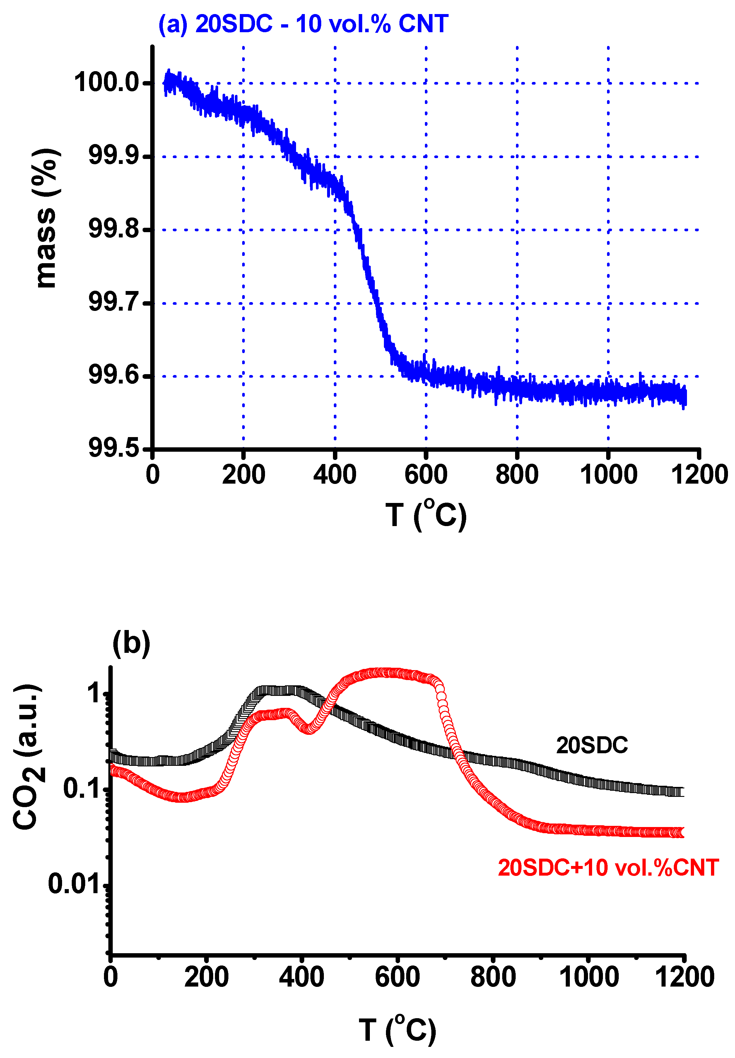
Figure 2 shows the results of the thermogravimetric analysis of the (90 vol% CeO2: 20 mol% Sm2O3–10 vol% carbon nanotube) composite in the room temperature–1200 °C range. The decrease of mass up to approximately 300 °C is ascribed to the release of physisorbed water. Mass loss is observed up to approximately 570 °C, corresponding to the removal of carbon nanotubes due to reaction with oxygen producing CO2. The detection of CO2 was confirmed by analysis of the output gas with the mass spectrometer. From 250 °C to 450 °C, CO2 is released from both solid electrolyte and the solid electrolyte–CNT mixture due to CO2 adsorbed in the samples during handling in the laboratory atmosphere. From 450 °C to 700 °C, a larger amount of CO2 is detected due to the reaction of the CNTs with oxygen pertaining to the synthetic air used in the experiment. The difference in the temperature ranges for the CNTs annihilation is due to the different location of the detection: the thermocouple of the TG equipment is close to the sample, but the travelling distance to the probe of the mass spectrometer is away (1 m) from the TG sample chamber gas outlet.
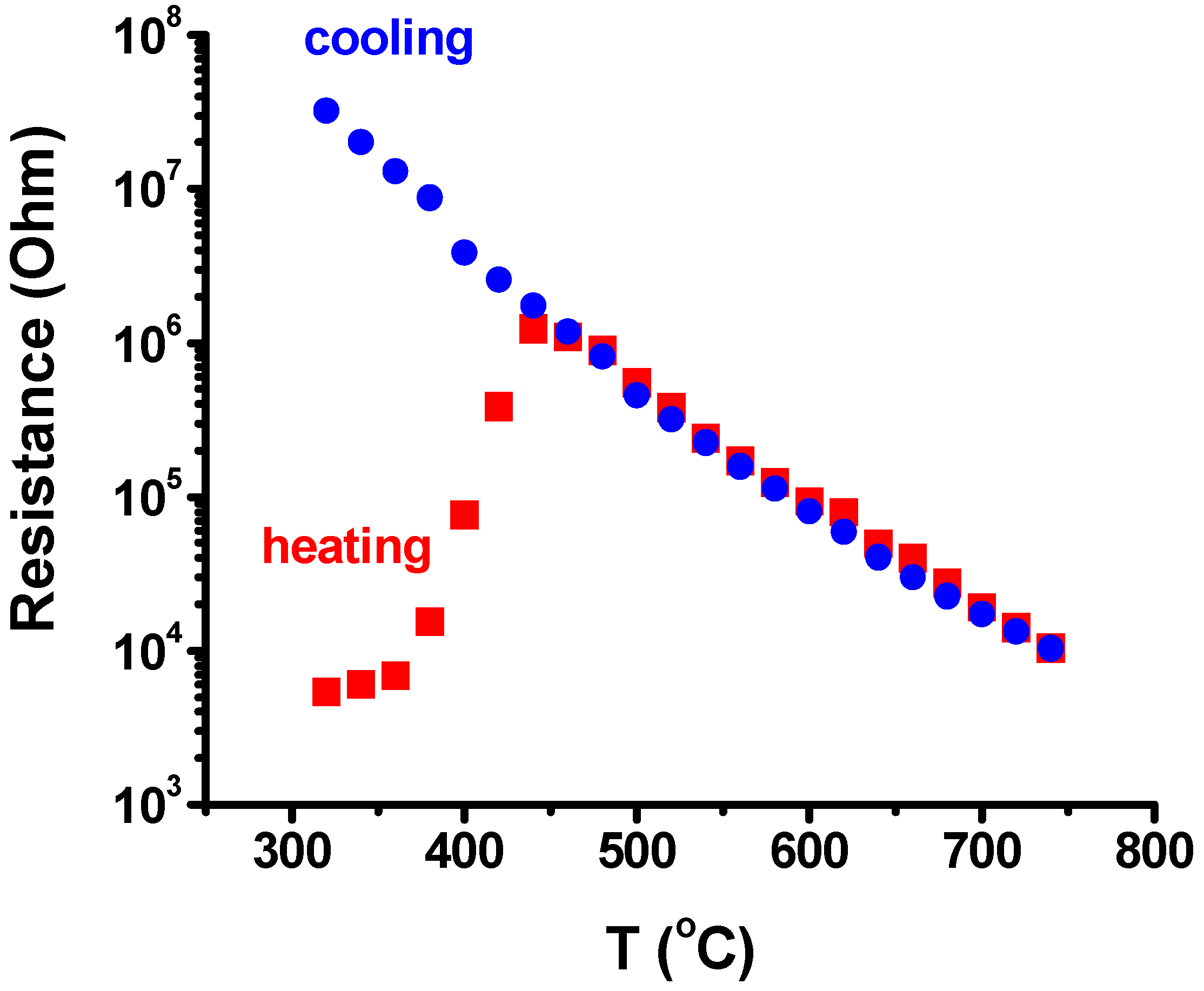
In good agreement with the results of mass loss in the thermogravimetric analysis (Figure 2), Figure 3 shows the dependence of the DC resistance of the 20SDC–10 vol% CNT composites during heating to and cooling from 750 °C. The electrical resistance of the composite is relatively low (3.5 kohm) at 250 °C due to the electronic conduction of the CNTs, and increases as the composite loses CNTs due to reaction with oxygen of the atmosphere; when the composite reaches approximately 450 °C, the resistivity decreases due to the oxide ion conduction of the solid electrolyte (electrolytic region).
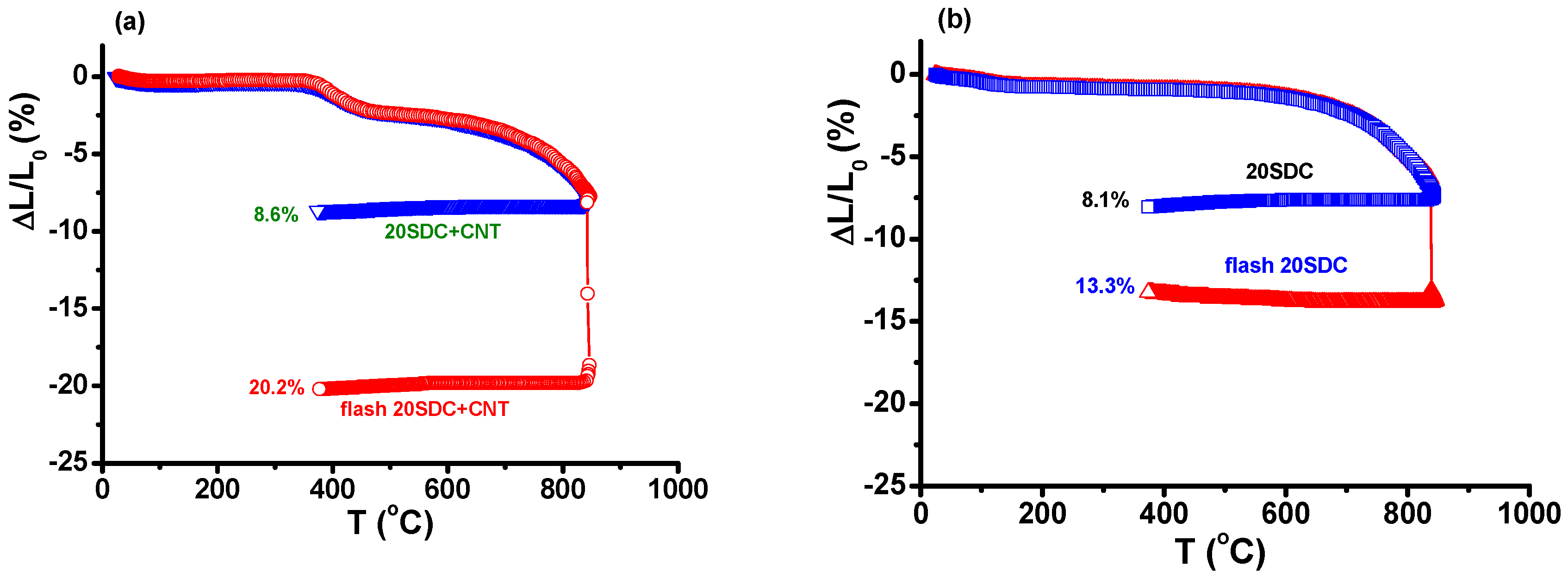
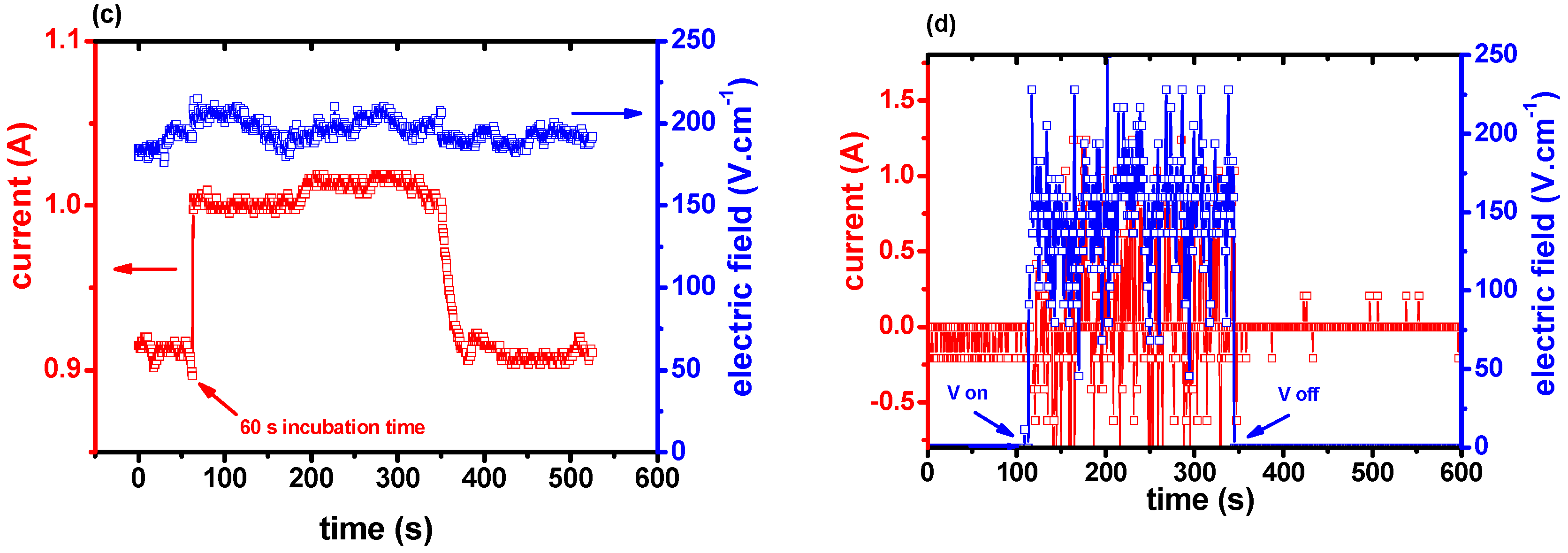
Figure 4 shows the dilatometric curves featuring the thickness shrinkage, from room temperature to 850 °C, of 20SDC + 10 vol% CNTs cylindrical pellets without and with the application of 210 V·cm−1 AC (1.1 kHz) electric field, limiting the current to 1 A to avoid thermal runaway that could occur with continuous increase of Joule heating. There is a 3% shrinkage of the sample with CNTs in the 400–450 °C range due to loss of CNTs, in agreement with the thermogravimetric data. The shrinkage levels attained were 8.6% and 20.2% without and with applying the electric field. Similar experiments were conducted in 20SDC samples without CNTs. The shrinkage levels were 8.1% and 13.3%, respectively, evidence of the enhancement of the densification by introducing CNTs in the 20SDC green pellets. Difference was also observed in the voltage–current temperature profiles, shown in the same figure. In the sample without CNTs, it takes 60 s for the flash event, i.e., for the electric current to reach the programmed value (1 A). The oscillation in the electric current might be due to the partial electronic conductivity of 20SDC, induced by the increase in temperature promoted by Joule heating. In the sample with CNTs, on the other hand, the applied voltage oscillates to yield a pulsed electric current through the sample. This might be due to the intermittent reaction of the CNTs with oxygen, yielding CO2 release.
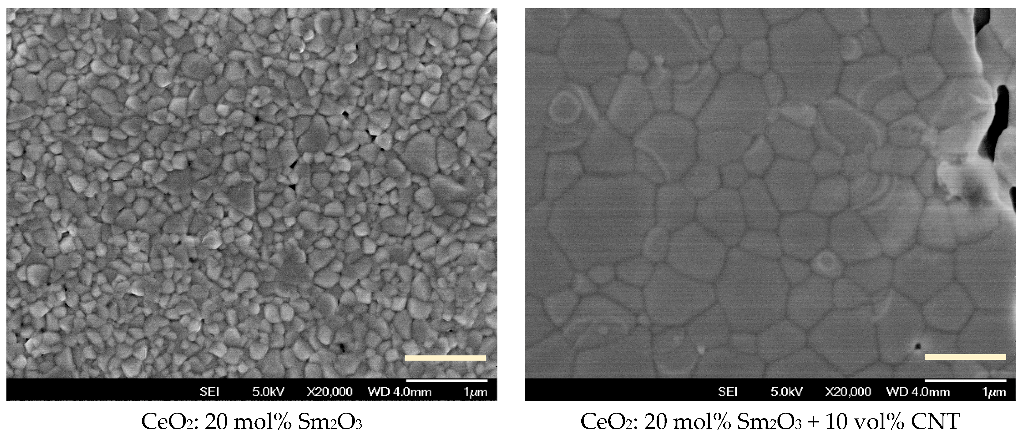
The Archimedes densities of the flash sintered 20SDC and 20SDC + 10 vol% CNT were 96.1% and 95.0% of the theoretical density. The scanning electron microscopy images of the flat surfaces of these samples, after polishing and thermally etching, are shown in Figure 5. The average grain size of the specimen with addition of CNTs is larger than in the specimens without CNTs (similar results were reported recently on SDC with graphite additions [63]); relatively larger intergranular pores are detected in the former, probably due to the enhanced Joule heating delivered to these specimens.
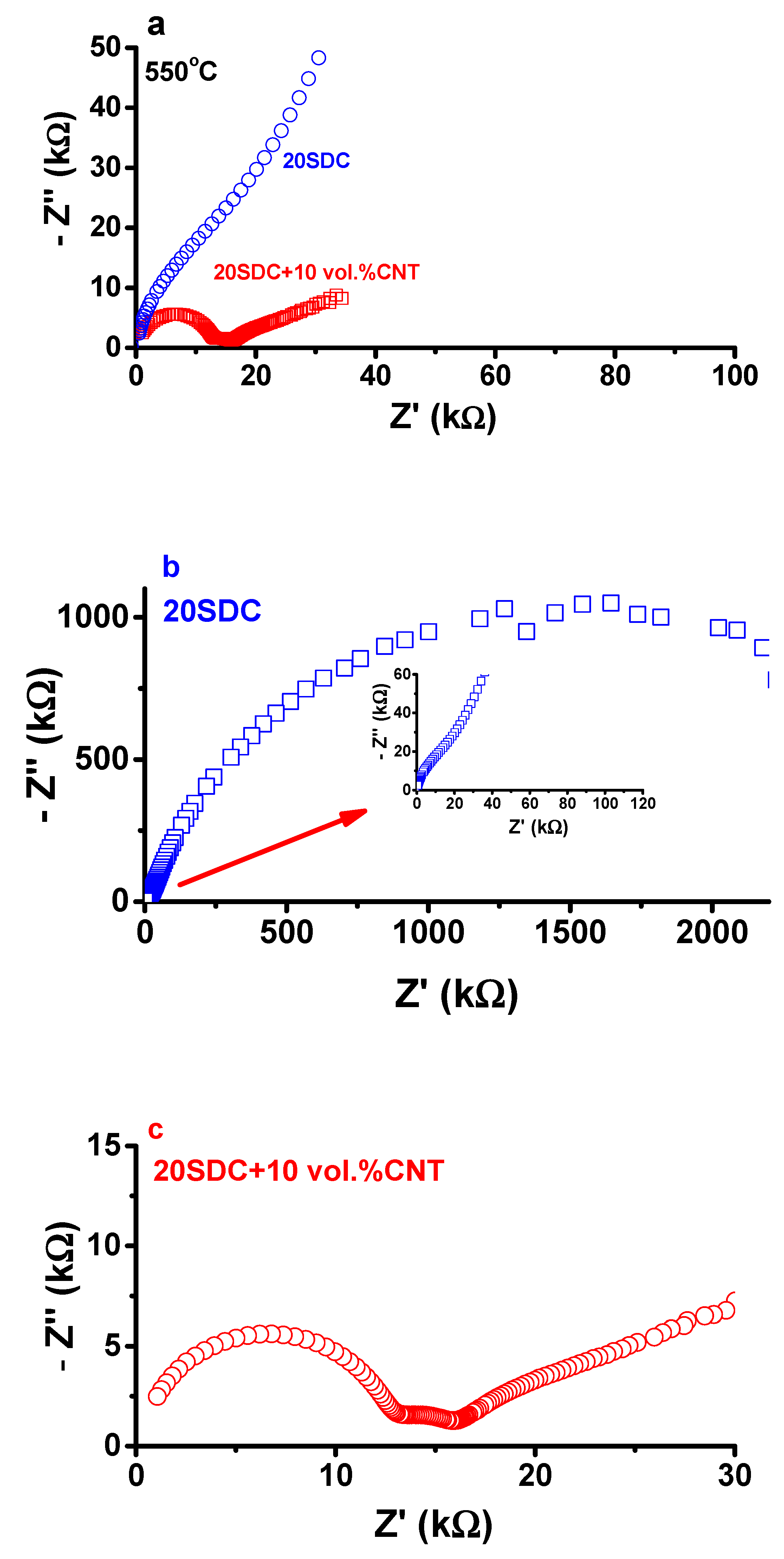
Figure 6 shows the [−Z″(f) × Z′(f)] impedance spectroscopy diagrams of the two flash sintered samples: CeO2: 20 mol% Sm2O3 and CeO2: 20 mol% Sm2O3 + 10 vol% carbon nanotubes. The improvement of the electrical conductivity with mixing carbon nanotubes with samaria-doped ceria is evident. The electrical resistivity of the former is 16.4 kohm, much lower than that of the latter, which is 3 Mohm.

4. Conclusions

The insertion of carbon nanotubes at the interparticle region of green pellets of ceria–samaria solid electrolytes promoted an increase of the thickness shrinkage of those composites when submitted to electric field-assisted (flash) sintering. It is proposed that the carbon nanotubes improve the percolation path for the electric current pulses, derived from the application of the electric field, enabling higher values of Joule heating with a consequent higher degree of densification, relatively larger grain sizes and intergranular pores. A pronounced decrease of the grain boundary resistivity is measured in specimens flash sintered with carbon nanotube addition, suggesting that the enhancement of Joule heating by the addition of carbon nanotubes greatly improved the grain-to-grain contact, being an alternative for promoting high densification of electroceramics.

Author Contributions

Conceptualization, R.M. and E.N.S.M.; methodology, R.M.; formal analysis, R.M. and E.N.S.M.; investigation, R.M., A.S.F. and E.N.S.M.; resources, R.M.; writing—original draft preparation, R.M.; writing—review and editing, R.M., A.S.F. and E.N.S.M.; supervision, R.M.; project administration, R.M.; funding acquisition, R.M., A.S.F. and E.N.S.M.

Funding

This research was funded by the Brazilian Agencies: CNEN, CNPq (Procs. 470952/2013-0, 303483/2013-0, 311803/2015-6, and 309295/2015-7–INCT of Carbon Nanomaterials), FAPESP (Proc. 2013/07296-2), and by CAPES (Finance Code 001).

Acknowledgments

One of the authors (R.M.) is grateful to Federal University of ABC for the Senior Visiting Researcher fellowship. Carbon nanotubes were produced at the Laboratory of Nanomaterials in the Physics Department of the Federal University of Minas Gerais, Brazil. FEG-SEM analysis was performed by the Laboratory of Microscopy and Microanalysis of CCTM-IPEN. To A.M. Figueiredo Neto, Institute of Physics, University of S. Paulo, Brazil, for making available the impedance analyzer.

Conflicts of Interest

The authors declare no conflict of interest.

References

  1. Cologna, M.; Rashkova, B.; Raj, R. Flash sintering of nanograin zirconia in <5 s at 850 °C. J. Am. Ceram. Soc. 2010, 93, 3556–3559. [Google Scholar] [CrossRef]
  2. Cologna, M.; Raj, R. Surface diffusion-controlled neck growth kinetics in early stage sintering of zirconia, with and without applied DC electrical field. J. Am. Ceram. Soc. 2011, 94, 391–395. [Google Scholar] [CrossRef]
  3. Obare, J.; Griffin, W.D.; Conrad, H. Effects of heating rate and DC electric field during sintering on the grain size distribution in fully sintered tetragonal zirconia polycrystals stabilized with 3% molar yttria (3Y-TZP). J. Mater. Sci. 2012, 47, 5141–5147. [Google Scholar] [CrossRef]
  4. Ji, W.; Parker, B.; Falco, S.; Zhang, J.Y.; Fu, Z.Y.; Todd, R.I. Ultra-fast firing: Effect of heating rate on sintering of 3YSZ, with and without an electric field. J. Eur. Ceram. Soc. 2017, 37, 2547–2551. [Google Scholar] [CrossRef]
  5. Conrad, H. Space charge and grain boundary energy in zirconia (3Y-TZP). J. Am. Ceram. Soc. 2011, 94, 3641–3642. [Google Scholar] [CrossRef]
  6. Carvalho, S.G.M.; Muccillo, E.N.S.; Muccillo, R. Electrical behavior and microstructural features of electric field-assisted and conventionally sintered 3 mol% yttria-stabilized zirconia. Ceramics 2018, 1, 2. [Google Scholar] [CrossRef]
  7. Muccillo, R.; Kleitz, M.; Muccillo, E.N.S. Flash grain welding in yttria stabilized zirconia. J. Eur. Ceram. Soc. 2011, 31, 1517–1521. [Google Scholar] [CrossRef]
  8. Muccillo, R.; Muccillo, E.N.S. An experimental setup for shrinkage evaluation during electric field-assisted flash sintering: Application to yttria-stabilized zirconia. J. Eur. Ceram. Soc. 2013, 33, 515–520. [Google Scholar] [CrossRef]
  9. Downs, J.A.; Sglavo, V.M. Electric field assisted sintering of cubic zirconia at 390 °C. J. Am. Ceram. Soc. 2013, 96, 1342–1344. [Google Scholar] [CrossRef]
  10. Steil, M.C.; Marinha, D.; Aman, Y.; Gomes, J.R.C.; Kleitz, M. From conventional ac flash-sintering of YSZ to hyper-flash and double flash. J. Eur. Ceram. Soc. 2012, 33, 2093–2101. [Google Scholar] [CrossRef]
  11. Muccillo, R.; Muccillo, E.N.S. Shrinkage control of yttria-stabilized zirconia during ac electric field-assisted sintering. J. Eur. Ceram. Soc. 2014, 34, 3871–3877. [Google Scholar] [CrossRef]
  12. Muccillo, E.N.S.; Carvalho, S.G.M.; Muccillo, R. Electric field-assisted pressureless sintering of zirconia–scandia–ceria solid electrolytes. J. Mater. Sci. 2018, 53, 1658–1671. [Google Scholar] [CrossRef]
  13. Hao, X.; Liu, Y.; Wang, Z.; Qiao, J.; Sun, K. A novel sintering method to obtain fully dense gadolinia doped ceria by applying a direct current. J. Power Sources 2012, 210, 86–91. [Google Scholar] [CrossRef]
  14. Valdebenito, J.U.; Akbari-Fakhrabadi, A.; Viswanathan, M.R. Effect of flash sintering on microstructure of Ce0.9Gd0.1O1.95 electrolyte fabricated by tape-casting. Mater. Lett. 2017, 209, 291–294. [Google Scholar] [CrossRef]
  15. Biesuz, M.; Del’Agli, G.; Spiridigliozzi, L.; Ferone, C.; Sglavo, V.M. Conventional and field-assisted sintering of nanosized Gd-doped ceria synthesized by co-precipitation. Ceram. Int. 2016, 42, 11766–11771. [Google Scholar] [CrossRef]
  16. Spiridigliozzi, L.; Biesuz, M.; Dell’Agli, G.; Di Bartolomeo, E.; Zurlo, F.; Sglavo, V.M. Microstructural and electrical investigation of flash-sintered Gd/Sm-doped ceria. J. Mater. Sci. 2017, 52, 7479–7488. [Google Scholar] [CrossRef]
  17. Jiang, T.; Wang, Z.; Zhang, J.; Hao, X.; Rooney, D.; Liu, Y.; Sun, W.; Qiao, J.; Sun, K.; Jia, T. Understanding the flash sintering of rare-earth-doped ceria for solid oxide fuel cell. J. Am. Ceram. Soc. 2015, 98, 1717–1723. [Google Scholar] [CrossRef]
  18. Li, J.; Guan, L.; Zhang, W.; Luo, M.; Song, J.; Song, X.; An, S. Sintering behavior of samarium doped ceria under DC electrical field. Ceram. Int. 2018, 44, 2470–2477. [Google Scholar] [CrossRef]
  19. Muccillo, R.; Muccillo, E.N.S.; Kleitz, M. Densification and enhancement of the grain boundary conductivity of gadolinium-doped barium cerate by ultra fast flash grain welding. J. Eur. Ceram. Soc. 2012, 32, 2311–2316. [Google Scholar] [CrossRef]
  20. Muccillo, R.; Esposito, V.; de Florio, D.Z.; Muccillo, E.N.S. Electric field-assisted pressureless sintering gadolinium-, yttrium- and samarium-doped barium cerate. Scr. Mater. 2018, 156, 6–9. [Google Scholar] [CrossRef]
  21. M’Peko, J.-C.; Francis, J.S.C.; Raj, R. Field-assisted sintering of undoped BaTiO3: Microstructure evolution and dielectric permittivity. J. Eur. Ceram. Soc. 2014, 34, 3655–3660. [Google Scholar] [CrossRef]
  22. Uehashi, A.; Yoshida, H.; Tokunaga, T.; Sasaki, K.; Yamamoto, T. Enhancement of sintering rates in BaTiO3 by controlling of DC electric current. J. Ceram. Soc. Japan 2015, 123, 465–468. [Google Scholar] [CrossRef]
  23. Nakagawa, Y.; Yoshida, H.; Uehashi, A.; Tokunaga, T.; Sasaki, K.; Yamamoto, T. Electric current-controlled synthesis of BaTiO3. J. Am. Ceram Soc. 2017, 100, 3843–3850. [Google Scholar] [CrossRef]
  24. Perez-Maqueda, L.A.; Gil-Gonzalez, E.; Perejon, A.; Lebrun, J.-M.; Sanchez-Jimenez, P.E.; Raj, R. Flash sintering of highly insulating nanostructured phase-pure BiFeO3. J. Am. Ceram. Soc. 2017, 100, 3365–3369. [Google Scholar] [CrossRef]
  25. Jesus, L.M.; Silva, R.S.; Raj, R.; M’Peko, J.-C. Electric field-assisted flash sintering of CaCu3Ti4O12: Microstructure characteristics and dielectric properties. J. Alloys Compd. 2016, 682, 753–758. [Google Scholar] [CrossRef]
  26. Zhang, Y.; Luo, J. Promoting the flash sintering of ZnO in reduced atmospheres to achieve nearly full densities at furnace temperatures of <120 °C. Scr. Mater. 2015, 106, 26–29. [Google Scholar] [CrossRef]
  27. Zhang, Y.; Jung, J.-I.; Luo, J. Thermal runaway, flash sintering and asymmetrical microstructural development of ZnO and ZnO-Bi2O3 under direct currents. Acta Mater. 2015, 94, 87–100. [Google Scholar] [CrossRef]
  28. Gao, H.; Asel, T.J.; Cox, J.W.; Zhang, Y.; Luo, J.; Brillson, L.J. Native point defect formation in flash sintered ZnO studied by depth-resolved cathodoluminescence spectroscopy. J. Appl. Phys. 2016, 120, 105302. [Google Scholar] [CrossRef] [Green Version]
  29. Muccillo, E.N.S.; Muccillo, R. Electric field-assisted sintering of tin dioxide with manganese dioxide addition. J. Eur. Ceram. Soc. 2014, 34, 3699–3706. [Google Scholar] [CrossRef]
  30. Muccillo, R.; Muccillo, E.N.S. Electric field-assisted flash sintering of tin dioxide. J. Eur. Ceram. Soc. 2014, 34, 915–923. [Google Scholar] [CrossRef]
  31. Gonzalez-Julian, J.; Guillon, O. Effect of electric field/current on liquid phase sintering. J. Am. Ceram. Soc. 2015, 98, 2018–2027. [Google Scholar] [CrossRef]
  32. Biesuz, M.; Sglavo, V.M. Current-induced abnormal and oriented grain growth in corundum upon flash sintering. Scr. Mater. 2018, 150, 82–86. [Google Scholar] [CrossRef]
  33. Lemke, F.; Rheinheimer, W.; Hoffmann, M.J. A comparison of power controlled flash sintering and conventional sintering of strontium titanate. Scr. Mater. 2017, 130, 187–190. [Google Scholar] [CrossRef]
  34. Shomrat, N.; Baltisnski, S.; Don, E.; Tsur, Y. The influence of doping on flash sintering conditions is SrTi1−xFexO3-δ. J. Eur. Ceram. Soc. 2017, 37, 179–188. [Google Scholar] [CrossRef]
  35. Straka, W.; Amoah, S.; Schwartz, J. Densification of thoria through flash sintering. MRS Commun. 2017, 7, 677–682. [Google Scholar] [CrossRef]
  36. Raftery, A.M.; da Silva, J.G.P.; Byler, D.D.; Andersson, D.A.; Uberuaga, B.P.; Stanek, C.R.; McClellan, K.J. Onset conditions for flash sintering of UO2. J. Nucl. Mater. 2017, 493, 264–270. [Google Scholar] [CrossRef]
  37. Valdez, J.A.; Byler, D.D.; Kardoulaki, E.; Francis, J.S.C.; McClellan, K.J. Flash sintering of stoichiometric and hyper-stoichiometric urania. J. Nucl. Mater. 2018, 505, 37–40. [Google Scholar] [CrossRef]
  38. Charalambous, H.; Jha, S.K.; Wang, H.; Phuah, X.L.; Wang, H.; Tsakalakos, T. Inhomogeneous reduction and its relation to grain growth of titania during flash sintering. Scr. Mater. 2018, 155, 37–40. [Google Scholar] [CrossRef]
  39. Candelario, V.M.; Moreno, R.; Todd, R.I.; Ortiz, A.L. Liquid-phase assisted flash sintering of SiC from powder mixtures prepared by aqueous colloidal processing. J. Eur. Ceram. Soc. 2017, 37, 485–498. [Google Scholar] [CrossRef]
  40. Yoshida, H.; Morita, K.; Nam, B.N.; Sakka, Y.; Yamamoto, T. Reduction in sintering temperature for flash-sintering of yttria by nickel cation-doping. Acta Mater. 2016, 106, 344–352. [Google Scholar] [CrossRef]
  41. Muccillo, R.; Muccillo, E.N.S. Electric field assisted sintering of electroceramics and in situ analysis by impedance spectroscopy. J. Electroceram. 2016, 38, 24–42. [Google Scholar] [CrossRef]
  42. Dancer, C.E.J. Flash sintering of ceramic materials. Res. Express 2016, 3, 102001. [Google Scholar] [CrossRef] [Green Version]
  43. Yu, M.; Grasso, S.; McKinnon, R.; Saunders, T.; Reece, M.J. Review of flash sintering: Materials, mechanisms and modelling. Adv. Appl. Ceram. 2016, 116, 24–60. [Google Scholar] [CrossRef]
  44. Todd, R.I.; Zapata-Solvas, E.; Bonilla, R.S.; Sneddon, T.; Wilshaw, P.R. Electrical characteristics of flash sintering: Thermal runaway of Joule heating. J. Eur. Ceram. Soc. 2015, 35, 1865–1877. [Google Scholar] [CrossRef]
  45. Hewitt, I.J.; Lacey, A.A.; Todd, R.I. A mathematical model for flash sintering. Math. Model. Nat. Phenom. 2015, 10, 77–89. [Google Scholar] [CrossRef]
  46. Jha, S.K.; Terauds, K.; Lebrun, J.; Raj, R. Beyond flash sintering in 3 mol% yttria stabilized zirconia. J. Ceram. Soc. Japan 2016, 124, 283–288. [Google Scholar] [CrossRef]
  47. Narayan, J. Grain growth model for electric field-assisted processing and flash sintering of materials. Scr. Mater. 2013, 68, 785–788. [Google Scholar] [CrossRef]
  48. Raj, R. Joule heating during flash-sintering. J. Eur. Ceram. Soc. 2012, 32, 2293–2301. [Google Scholar] [CrossRef]
  49. Naik, K.S.; Sglavo, V.M.; Raj, R. Flash sintering as a nucleation phenomenon and a model thereof. J. Eur. Ceram. Soc. 2014, 34, 4063–4067. [Google Scholar] [CrossRef]
  50. Qin, W.; Majidi, H.; Yun, J.; van Benthem, K. Electrode effects on microstructure formation during flash sintering of yttrium stabilized zirconia. J. Am. Ceram. Soc. 2016, 99, 2253–2259. [Google Scholar] [CrossRef]
  51. Cologna, M.; Francis, J.S.C.; Raj, R. Field assisted and flash sintering of alumina and its relationship to conductivity and MgO doping. J. Eur. Ceram. Soc. 2011, 31, 2827–2837. [Google Scholar] [CrossRef]
  52. Francis, J.S.C.; Cologna, M.; Montinaro, D.; Raj, R. Flash sintering of anode-electrolyte multilayers for SOFC applications. J. Am. Ceram. Soc. 2013, 96, 1352–1354. [Google Scholar] [CrossRef]
  53. Jha, S.K.; Lebrun, J.M.; Raj, R. Phase transformation in the alumina–titania system during flash sintering experiments. J. Eur. Ceram. Soc. 2016, 36, 733–739. [Google Scholar] [CrossRef]
  54. Zhang, X.S.; Yang, L.W.; Liu, H.T. High temperature conduction behavior of carbon nanotube fiber from 25 °C to 1100 °C. Appl. Phys. Lett. 2018, 112, 164103. [Google Scholar] [CrossRef]
  55. Arabacı, A.; Serin, Ö.; Sarıboga, V.; Öksüzömer, M.F. Characterization of Sm and Nd co-doped ceria-based electrolyte materials. Acta Phys. Polonica A 2016, 129, 524–527. [Google Scholar] [CrossRef]
  56. Iijima, S. Helical microtubules of graphitic carbon. Nature 1991, 354, 56–58. [Google Scholar] [CrossRef]
  57. Volder, M.F.L.; Tawfick, S.H.; Baughman, R.H.; Hart, A.J. Carbon nanotubes: Present and future commercial applications. Science 2013, 339, 535–539. [Google Scholar] [CrossRef]
  58. Halder, R.; Sarkar, S.; Bandyopadhyay, S.; Chakraborti, P.C. Sintering and tribomechanical properties of gel-combustion-derived nano-alumina and its composites with carbon nanotubes. J. Mater. Sci. 2018, 53, 8989–9001. [Google Scholar] [CrossRef]
  59. Available online: https://fuelcellmaterials.com/products/powders/electrolyte-powders/samarium-doped-ceria-20-sm-nanopowder/ (accessed on 10 January 2019).
  60. Da Cunha, T.H.R.; de Oliveira, S.; Martins, I.L.; Geraldo, V.; Miquita, D.; Ramos, S.L.M.; Lacerda, R.G.; Ladeira, L.O.; Ferlauto, A.S. High-yield synthesis of bundles of double- and triple-walled carbon nanotubes on aluminum flakes. Carbon 2018, 133, 53–61. [Google Scholar] [CrossRef]
  61. Available online: https://www.tosoh.com/our-products/advanced-materials/zirconia-grinding--dispersion-media (accessed on 10 January 2019).
  62. Kleitz, M.; Kennedy, J.H. Resolution of multicomponent impedance diagrams. In Fastion Transport in Solids; Mundy, J.N., Shenoy, G.K., Vashishta, P., Eds.; Elsevier North Holland, Inc.: New York, NY, USA, 1979; pp. 185–188. [Google Scholar]
  63. Guan, L.; Li, J.; Song, X. Graphite assisted flash sintering of Sm2O3 doped CeO2 ceramics at the onset temperature of 25 °C. Scr. Mater. 2019, 159, 72–75. [Google Scholar] [CrossRef]
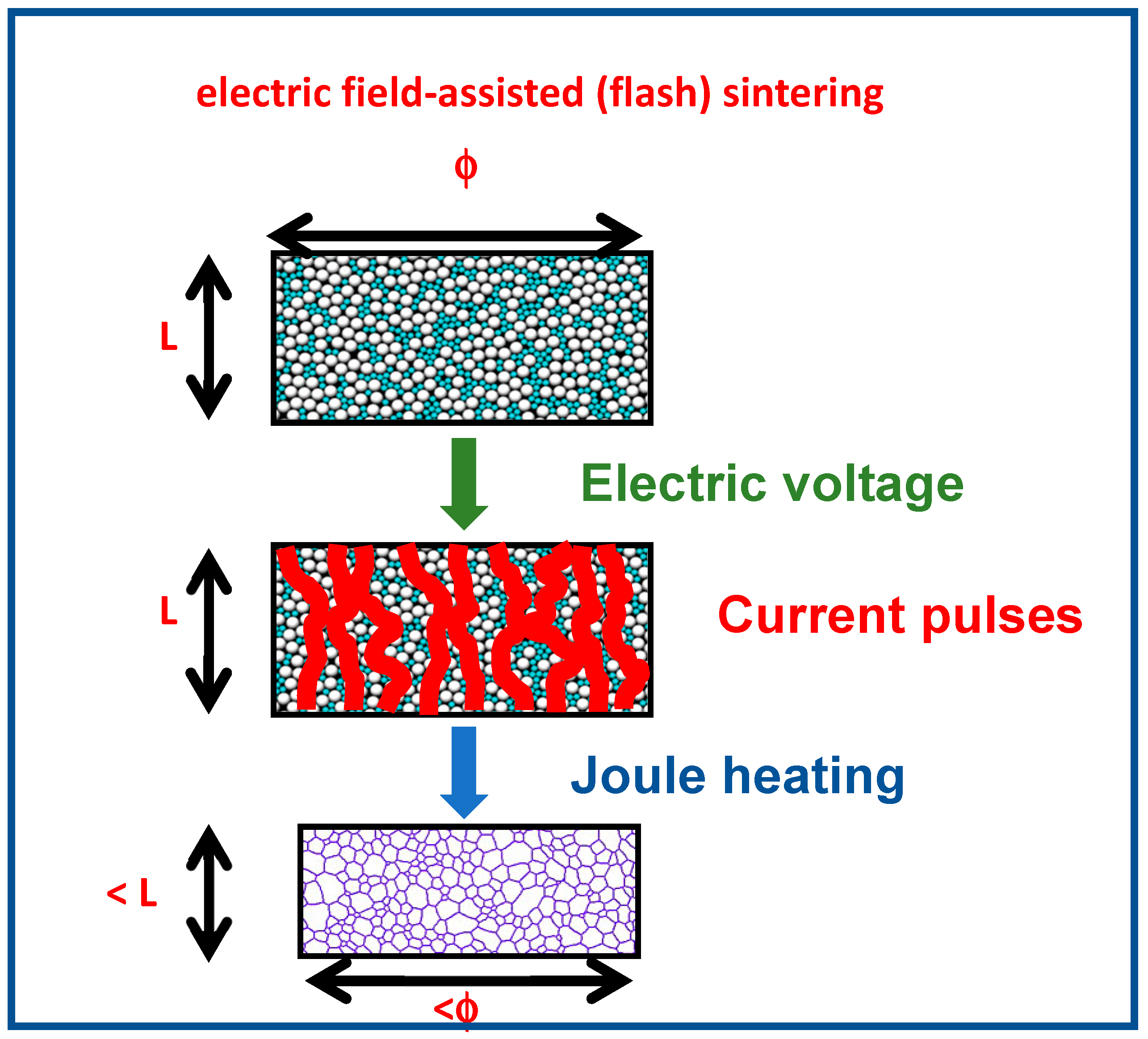
Figure 1. Sketch of the evolution of the dimensions of a composite ceramic pellet during electric field-assisted sintering. White spheres: samaria-doped ceria (SDC); green spheres: carbon nanotubes (CNT).
Ceramics 02 00006 g001
Figure 2. (a) Thermogravimetric curve of CeO2: 20 mol% Sm2O3 mixed to 10 vol% carbon nanotubes (CNTs); (b) mass spectrometry evolved gas analysis of CeO2: 20 mol% Sm2O3 and CeO2: 20 mol% Sm2O3 mixed to 10 vol% carbon nanotubes.
Ceramics 02 00006 g002
Figure 3. Evolution of the DC electrical resistance of CeO2: 20 mol% Sm2O3–10 vol% CNT composite during heating to and cooling from 750 °C in air inside the dilatometer.
Ceramics 02 00006 g003
Figure 4. Top: dilatometric curves of CeO2: 20 mol% Sm2O3 with (a) and without (b) 10 vol% CNT pellets with application of 210 V·cm−1 at 850 °C. Bottom: corresponding I, V curves (c,d) during application of the electric field.
Ceramics 02 00006 g004aCeramics 02 00006 g004b
Figure 5. Scanning electron microscopy images of flash sintered CeO2: 20 mol% Sm2O3 and CeO2: 20 mol% Sm2O3 mixed to 10 vol% CNT; bar size = 1 µm.
Ceramics 02 00006 g005
Figure 6. Impedance spectroscopy diagrams of (a) CeO2: 20 mol% Sm2O3–10 vol% CNT) composite pellets and CeO2: 20 mol% Sm2O3 flash sintered at 850 °C; (b) expanded views of CeO2: 20 mol% Sm2O3 (with zoom) and (c) (CeO2: 20 mol% Sm2O3–10 vol% CNT). Temperature of measurement: 550 °C.
Ceramics 02 00006 g006