
LLM-Driven Modeling and Decision Support Methods for Cross-Domain Collaborative Mission Systems


Abstract
1. Introduction
- 1.
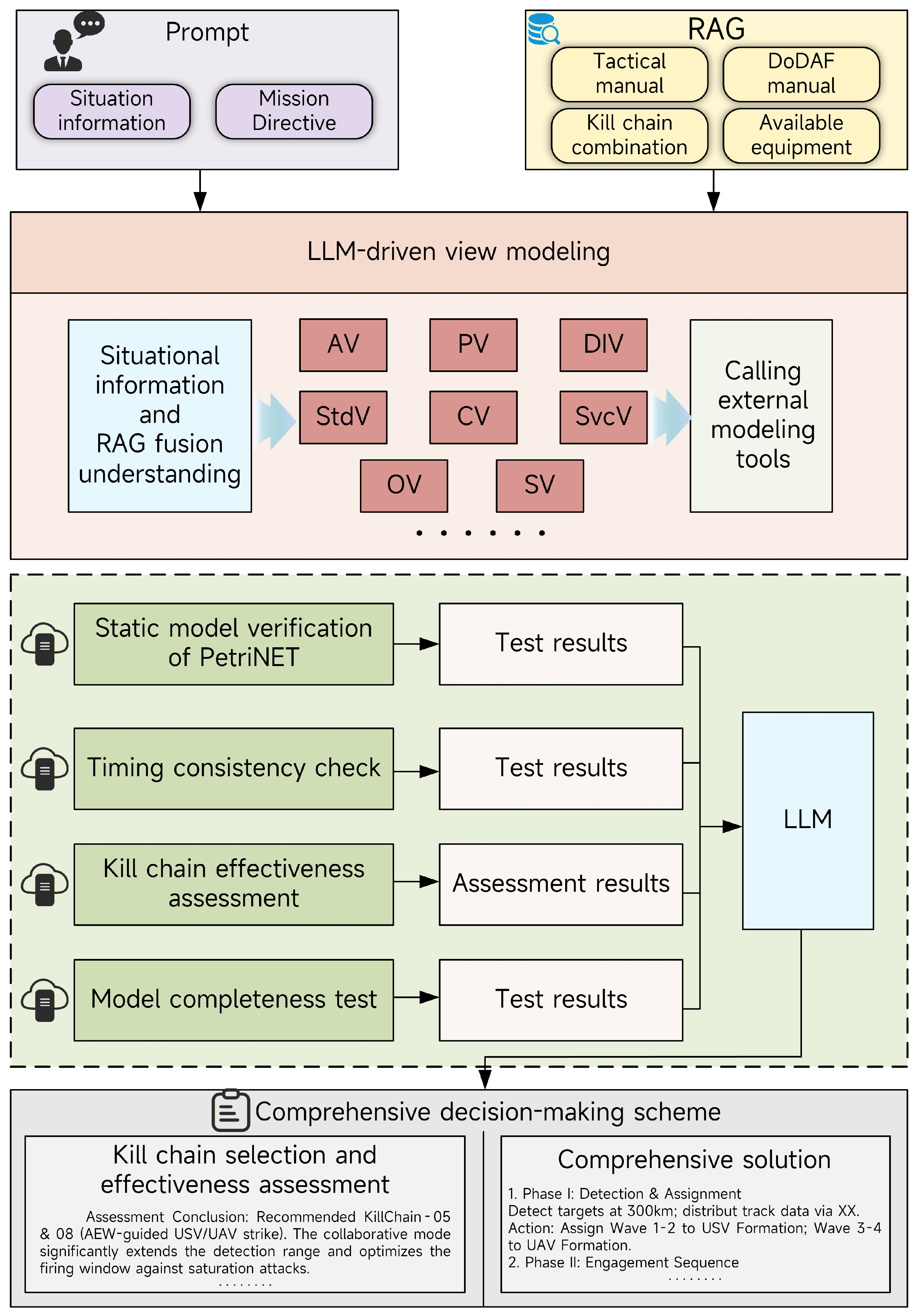
- An innovative systems engineering framework for transparent modeling is proposed. We architect a novel integration pipeline that fuses LLMs with the DoDAF standard. By leveraging RAG to align natural-language directives with standardized architectural views, this method effectively bridges the semantic gap. Importantly, we strictly distinguish the framework’s interpretability into two dimensions: the intrinsic interpretability of the underlying reasoning pipeline, guaranteed by the rigorous structural mapping of DoDAF and formal Petri net verification, and the post hoc explainability of the outputs, provided by the LLM-generated reasoning traces. This dual-layered transparency mitigates the “hallucination” risks inherent in standalone generative models.
- 2.
- A hybrid computing framework is established for adaptive decision making. We construct a closed-loop verification mechanism that combines Petri nets for static logic validation with Monte Carlo simulations for dynamic effectiveness evaluation. This hybrid approach enables the system to handle the uncertainty of stochastic battlefield environments and ensures that generated kill chains are both logically sound and operationally effective.
- 3.
- The practical application efficacy is validated in multidisciplinary scenarios. We apply the proposed method to a cross-domain collaborative interception mission involving heterogeneous UAV and USV formations. Experimental results demonstrate that this AI-empowered system improves interception efficiency and adaptability compared to traditional non-collaborative approaches, providing a verified reference for UAV-USV maritime defense mission systems.
2. Related Work
2.1. DoDAF System Modeling and Analysis Methods
2.1.1. Overview of DoDAF Methodology
- 1.
- DoDAF method.In the field of mission system research, the DoDAF is currently the most widely adopted methodology for modeling and analyzing the composition, functions, and interactions of military systems. The framework has evolved through several major iterations, with the latest version, DoDAF 2.02, released in January 2015 [4]. Since then, its military applications have been extensively explored. In 2019, Posherstnik et al. [5] proposed a DoDAF-based framework for joint command and control, focusing on electromagnetic spectrum interoperability. Subsequently, Beery et al. [6] applied DoDAF to defense engineering management in 2021 to guide the development of system architecture products. In 2022, Xu et al. [7] introduced a modeling method for the precision strike process in joint anti-carrier operations, utilizing SysML to describe the system architecture. Zhuo [8] later proposed a concept model construction method based on DoDAF in 2023, developing event description and state space models for a territorial sea defense system, which were validated through simulation. Zhao et al. [9] implemented the modeling and simulation of an unmanned landing combat system, completing the campaign-level joint landing concept design utilizing the All Viewpoint (AV) and Operational Viewpoint (OV) models of DoDAF. Similarly, Zhao et al. [10] analyzed the anti-drone swarm combat architecture, identifying command relationships, information flows, and state transitions. In 2024, Zhao et al. [11] proposed an iterative design method combining DoDAF with ExtendSim executable models, demonstrating its feasibility in an anti-submarine warfare context. In summary, DoDAF has demonstrated a high level of maturity in mission system modeling and concept design.
- 2.
- UAF method.The Unified Architecture Framework (UAF) is an architectural design methodology for modeling relationships between organizations and systems, released by the Object Management Group (OMG) in 2017. In 2021, Hause et al. [12] proposed a UAF-based cybersecurity defense modeling method, defining defense objectives and their integration into defensive operations through a set of security viewpoints. In 2023, Lu et al. [13] introduced a UAF-based architecture modeling method for the air defense and anti-missile combat system of a carrier strike group. This study primarily focused on the modeling process and combat requirements but lacked a detailed discussion on engineering applications. Dong [14] implemented the modeling and simulation of air traffic control scenarios by defining functional domains based on UAF. Furthermore, Martin et al. [15] proposed a UAF-based method to model the mission analysis process in combat planning, achieving the description of combat mission concepts and entity attributes.
2.1.2. Introduction to DoDAF Views
2.2. LLM-Driven Multi-View Modeling Analysis of System
3. LLM-Driven DoDAF System Modeling and Decision Generation Framework
3.1. Overview of the Framework
3.2. Prompt Engineering
3.3. Situation- and Resources-Based DoDAF Modeling
3.3.1. UAV-USV System Modeling Steps and Implementation Methods
- 1.
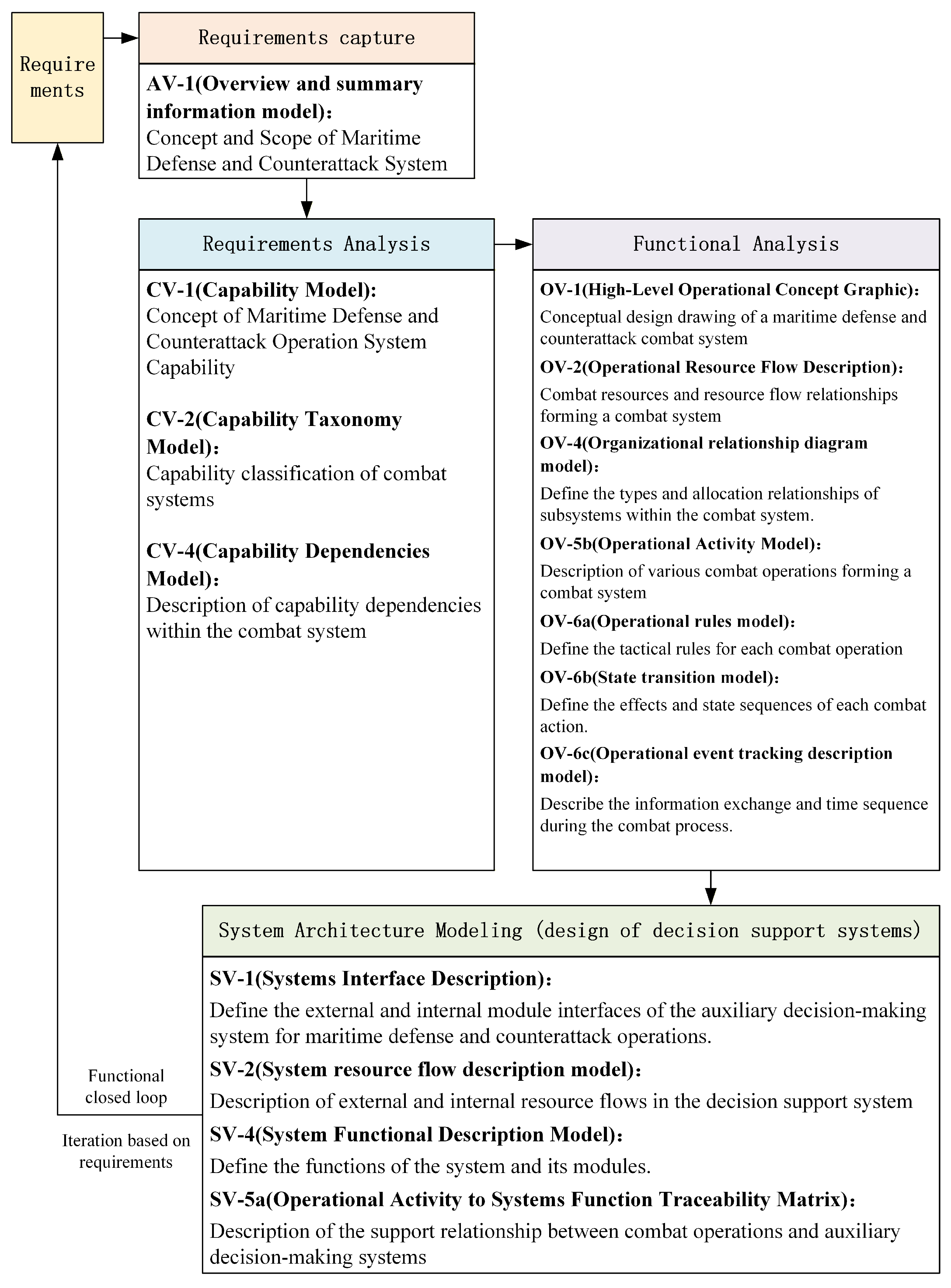
- Requirement Capture: Construction of System All-Viewpoint Model. In the requirement capture stage, using the AV-1 Overview and Summary Information model and based on the mission scenario and system concept, the top-level vision of the system mission is developed. This covers the system mission intent, thereby forming an intuitive understanding of system requirements.
- 2.
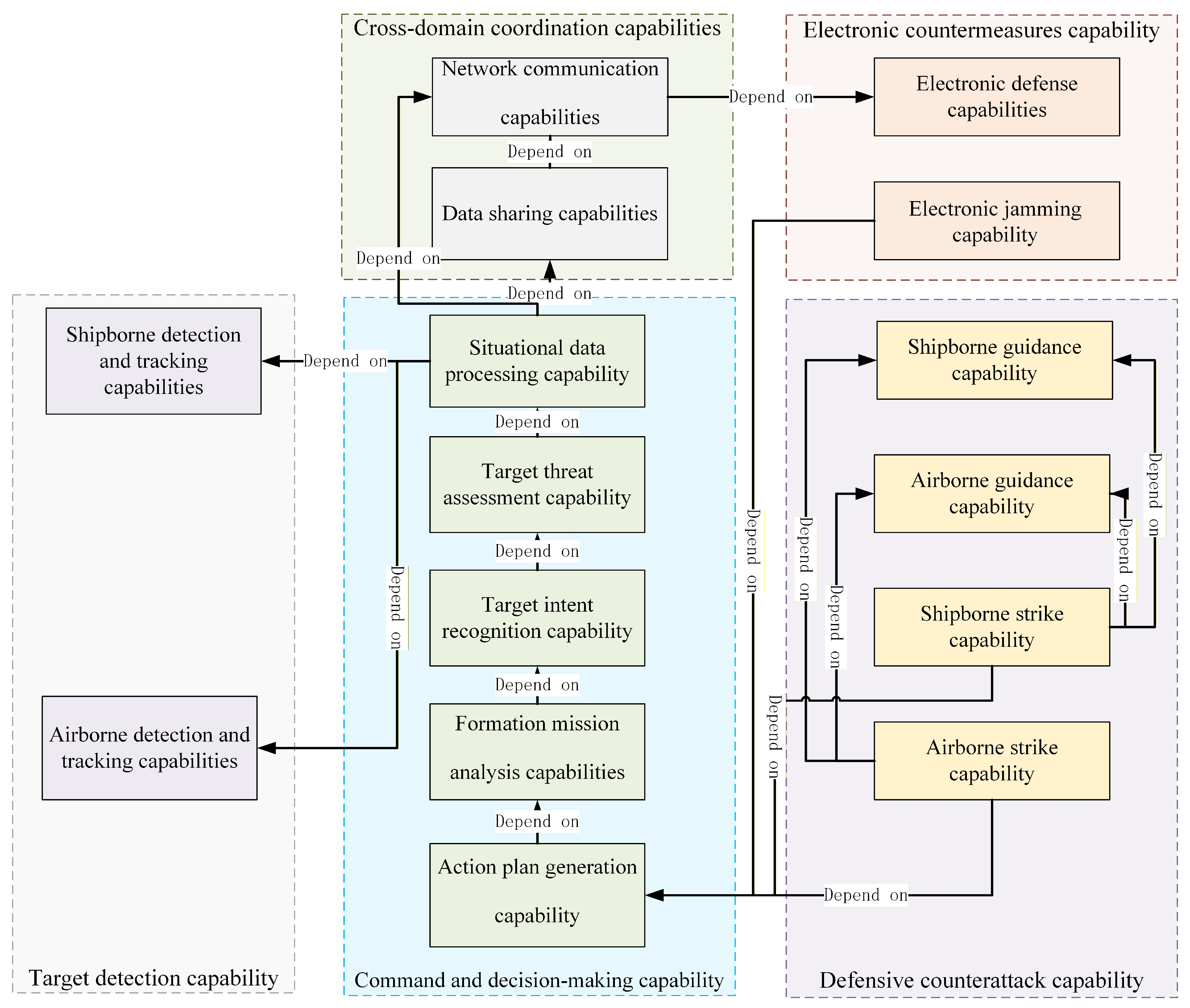
- Requirement Analysis: Construction of System Capability Model. Based on the system overview formed in the requirement capture stage, the system capabilities and taxonomy required to support the mission concept are further decomposed using the CV-1 Capability Vision model and the CV-2 Capability Taxonomy model. Subsequently, the CV-4 Capability Dependencies model is used to analyze and define the capability dependencies among systems within the mission architecture.
- 3.
- Functional Analysis: Construction of System Mission View Model. In the functional analysis stage, the conceptual design of the maritime defense and counterattack mission system is first completed based on the OV-1 High-Level Operational Concept Graphic [28]. Subsequently, relationships between mission resources are established via the OV-2 Mission Resource Flow Description model. On this basis, mission actions, rules, and effects are defined using the OV-5b, OV-6a, and OV-6b models, respectively, while mission event tracking is conducted using the OV-6c model.
- 4.
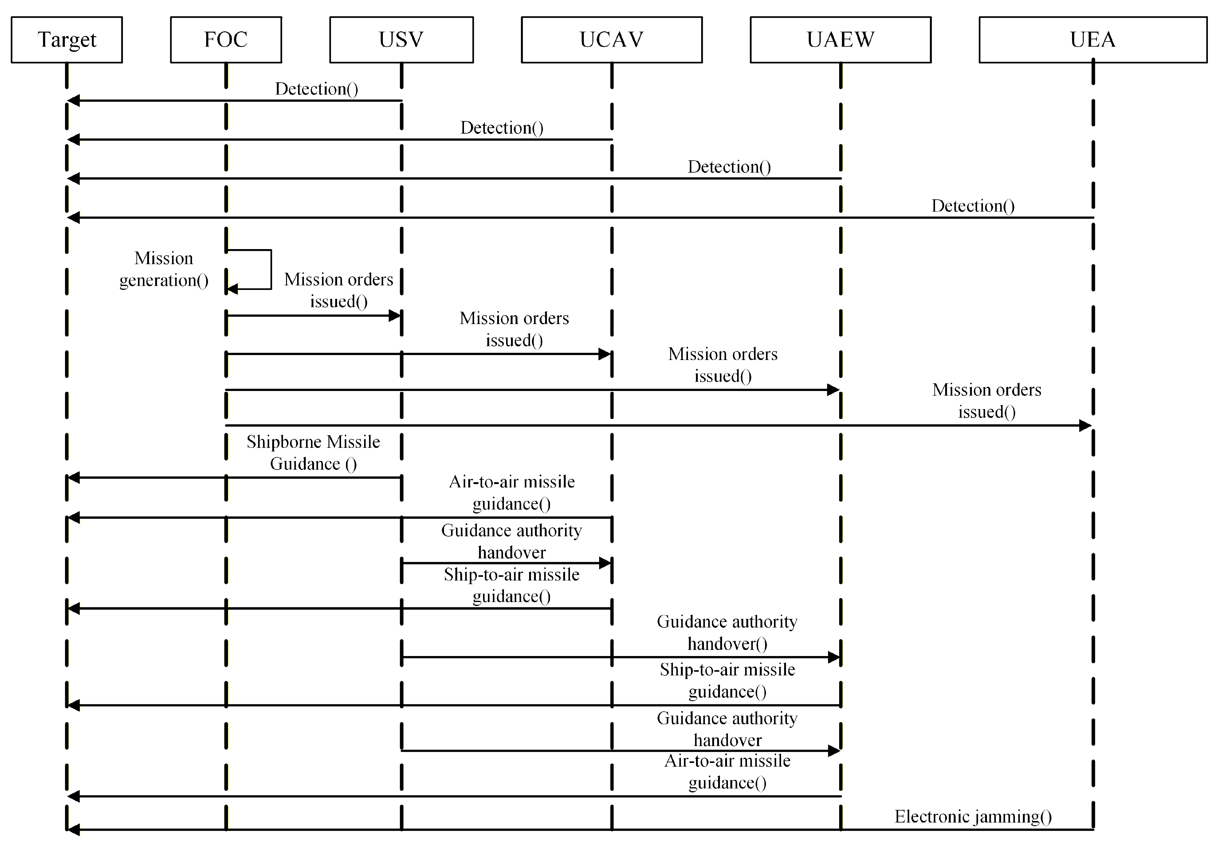
- Functional Modeling: Construction of System View Model Upon completion of the aforementioned processes, the component analysis of the auxiliary decision-making system is achieved through functional models such as the SV-1 Systems Interface Description, SV-2 Systems Resource Flow Description, and SV-4 Systems Functionality Description under the System View. The entire process is illustrated in Figure 2.
3.3.2. Construction of System Panoramic View Model
3.3.3. Construction of System Capability View Model
- 1.
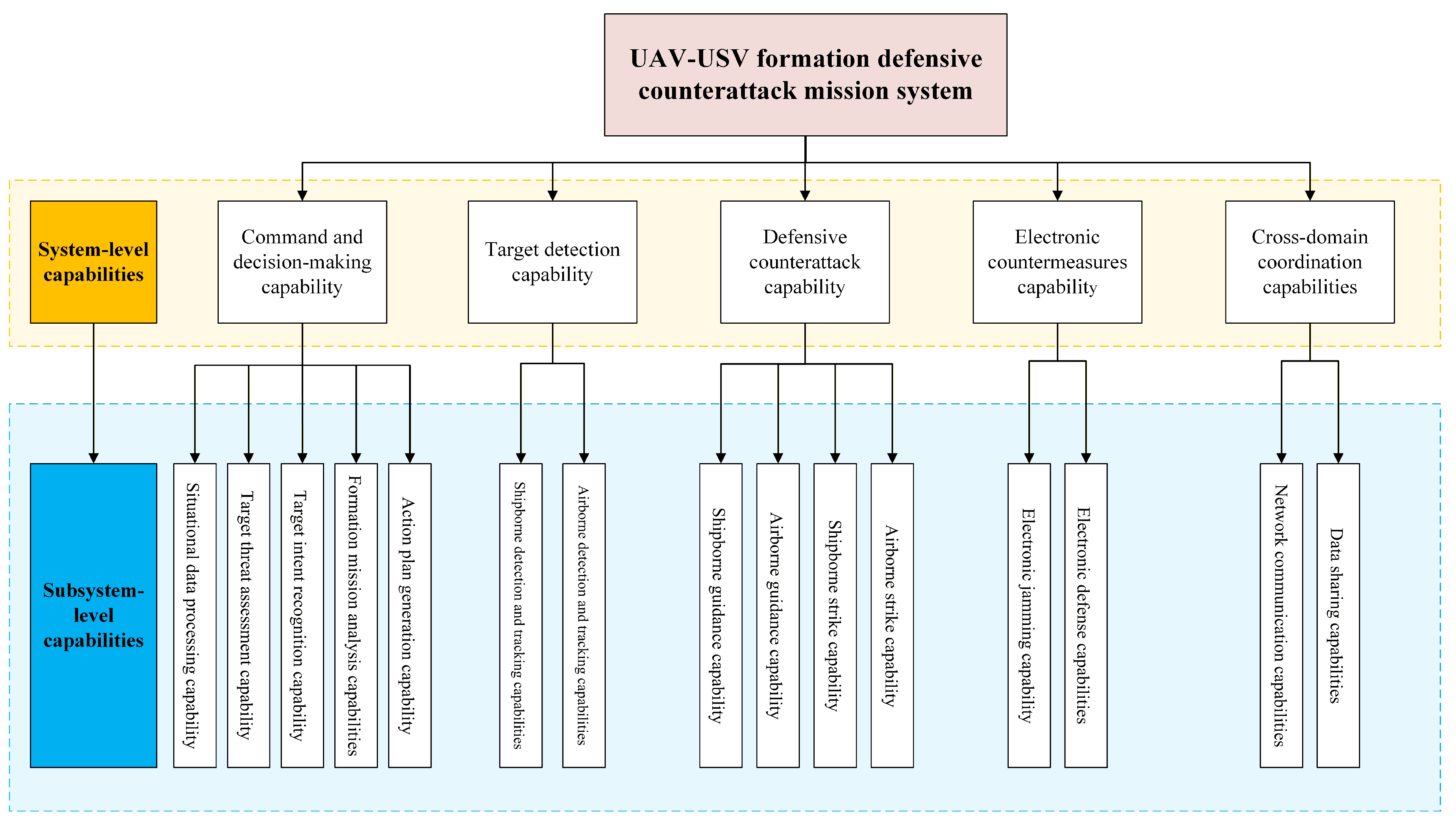
- The Command and Decision Capability refers to the integrated formation-level command capability provided by the auxiliary decision-making system. At the subsystem level, primarily, it requires Situational Data Processing Capability to ensure the accuracy of situational information fusion. Secondly, it must provide an essential Target Threat Assessment Capability. Subsequently, it enables Target Intent Identification based on target characteristics. On this basis, it facilitates Formation Mission Analysis and COA Generation. This procedure constitutes a critical decision-making process constrained by the OODA loop, thereby enabling a closed-loop operation at the formation level of the kill chain.
- 2.
- Target Detection Capability refers to the ability to detect and track targets provided by shipborne or airborne sensors (specifically radars). Shipborne detection and tracking capabilities are typically supplied by radars mounted on Unmanned Surface Vessels (USVs). Airborne detection and tracking capabilities are provided by Unmanned Airborne Early Warning (UAEW) aircraft and Unmanned Combat Aerial Vehicles (UCAVs).
- 3.
- Defense Operations Capability is constituted by USVs and UAVs equipped with interception weaponry. The effectiveness of target neutralization is determined jointly by the guidance and strike capabilities of the weapons. Guidance serves as a prerequisite for completing target destruction within the kill chain. Since the defensive counterattack mission of the UAV-USV formation can be executed through cross-domain sea-air coordination, UAEWs, UCAVs, and USV radars can all provide guidance functions. This introduces complexity into cross-domain collaborative decision-making and COA generation.
- 4.
- Electronic Countermeasures Capability primarily comprises Electronic Jamming Capability and Electronic Defense Capability. Electronic Jamming Capability refers to the support jamming provided by Unmanned Electronic Attack (UEA) aircraft. Electronic Defense Capability refers to the ability to guarantee information transmission assurance among various mission groups or units within the formation.
- 5.
- Cross-Domain Coordination Capability consists of Networked Communication Capability and Data Sharing Capability. Networked Communication Capability is typically determined by the data link capabilities deployed on individual platforms within the formation. Data Sharing Capability refers to the information-sharing ability within the formation driven by the network communication system. It encompasses functions such as collaborative data processing and dissemination, enabling the formation to possess collaborative detection, situational sharing, and target tracking capabilities.
3.3.4. Construction of System Mission View Model
- 1.
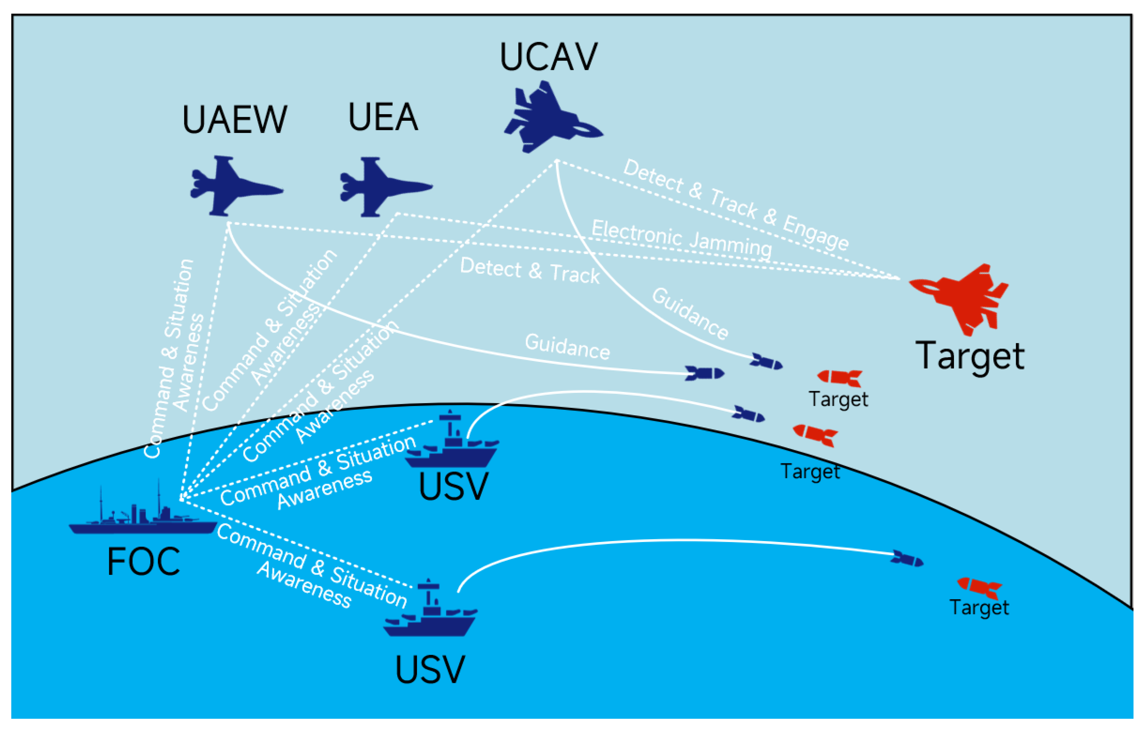
- OV-1 High-Level Operational Concept Graphic. The maritime defense and counterattack mission system proposed in this paper focuses on the UAV-USV formation. Designed for defensive counterattack mission scenarios, it enables intelligent target threat assessment, formation mission analysis, and COA (Course of Action) generation through networked collaboration among C2 systems (auxiliary decision-making systems) [29], sensor systems, interception systems, and electronic countermeasure systems. This establishes a UAV-USV formation defense and counterattack mission architecture characterized by intelligent decision support. Figure 5 illustrates the OV-1 High-Level Operational Concept Graphic for this mission system.The OV-1 High-Level Operational Concept Graphic designed in this section is tailored for the maritime defense and counterattack scenario of the UAV-USV formation. It primarily incorporates key subsystem elements involved in the scenario, including the UAV Launch Platform, USV Formation, Unmanned Airborne Early Warning (UAEW) Formation, Unmanned Combat Aerial Vehicle (UCAV) Formation, and Unmanned Electronic Attack (UEA) Formation. The hostile targets are predominantly identified as aerial threats, such as missiles or aircraft.
- 2.
- OV-2 Operational Resource Flow Description. Further analysis based on the OV-1 High-Level Operational Concept Graphic yields the OV-2 Operational Resource Flow Description. This model characterizes the resource-interaction requirements among subsystem nodes within the mission architecture. Systematically identifying and analyzing these resource interaction requirements provides a critical basis for the requirements justification and interface analysis of the auxiliary decision-making system. Table 3 presents the OV-2 Operational Resource Flow Description.In this section, resource flows are categorized into Situational Flows and Command and Control (C2) Flows. Situational Flows primarily comprise feedback information derived from target detection, whereas C2 Flows are typified by command resources such as operational directives and guidance data.
- 3.
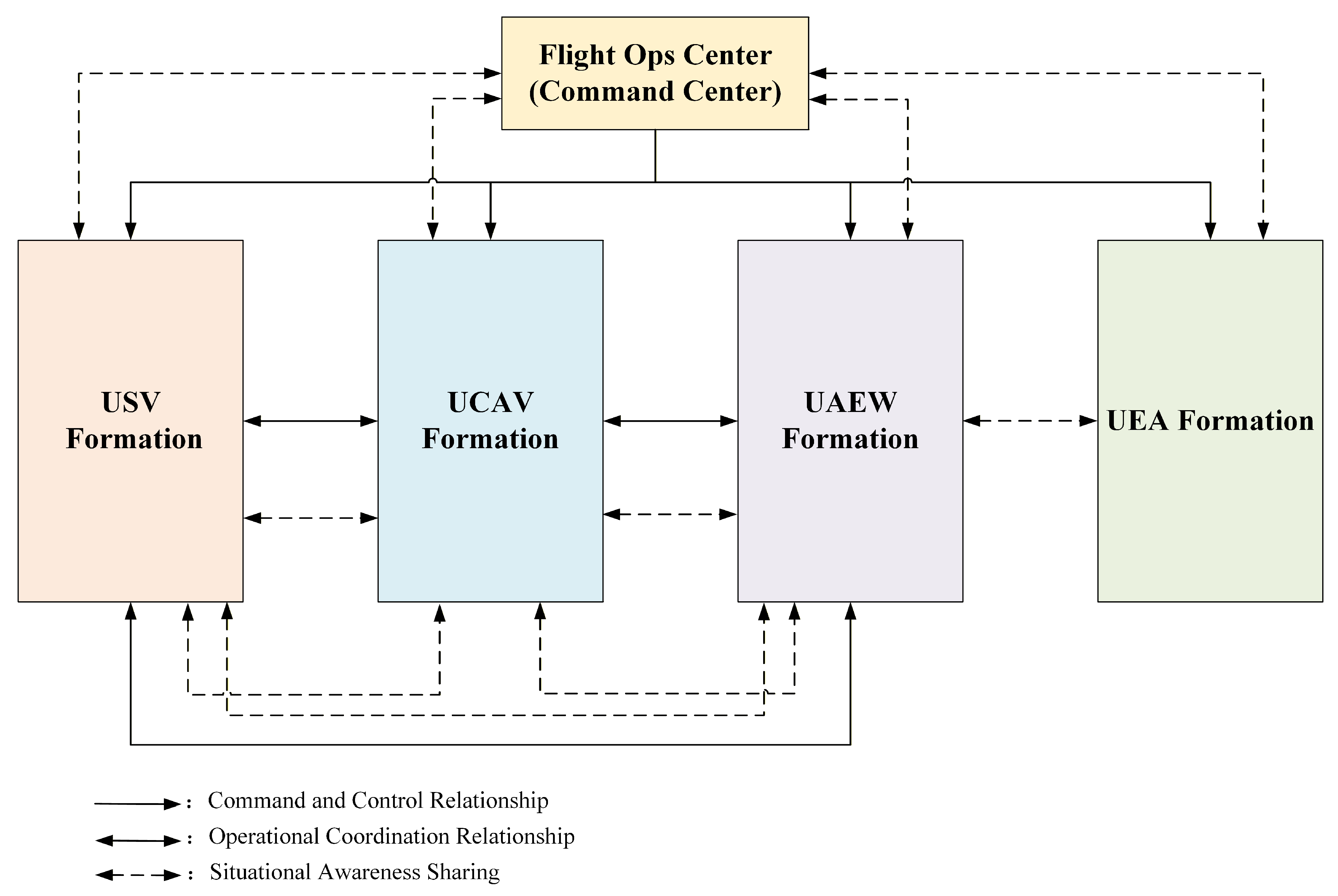
- OV-4 Organizational Relationships Chart Model. The OV-4 Organizational Relationships Chart primarily illustrates the types, quantities, and compositional hierarchies of subsystems within the architecture. Figure 6 defines the organizational relationships for the maritime defense and counterattack mission. Typically, the composition of the UAV-USV formation is determined based on mission requirements prior to assembly.Conventional UAV-USV formations are generally structured around the Flight Ops Center. They comprise USV, UCAV, UAEW, and UEA formations, thereby forming a joint combat force integrated with diverse equipment. Table 4 presents an example of such a defense and counterattack formation configuration, omitting other non-primary combat elements.
- 4.
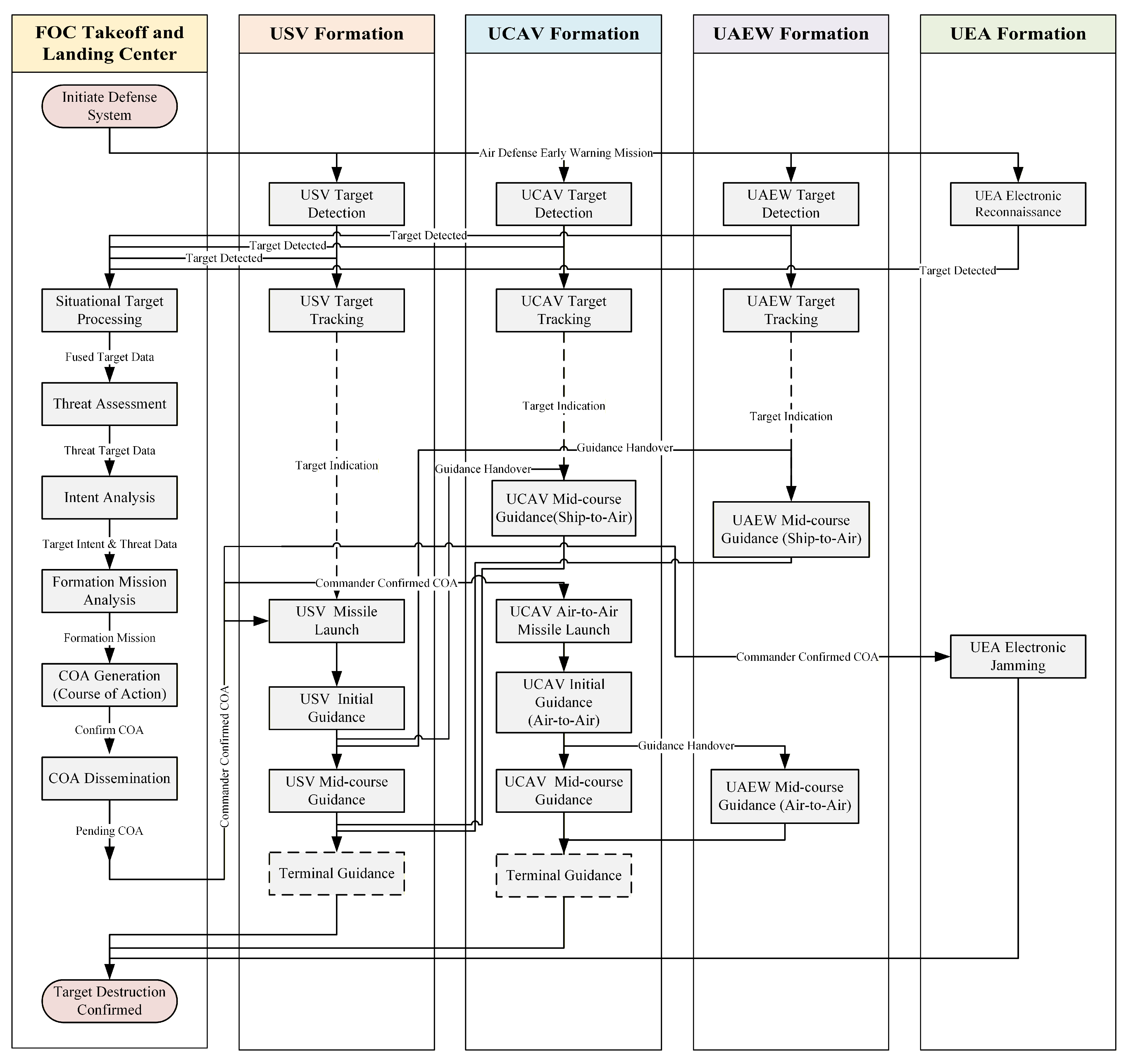
- OV-5b Operational Activity Model. Based on the OV-1 High-Level Operational Concept Graphic, OV-2 Operational Resource Flow Description, and OV-4 Organizational Relationships Chart, the OV-5b Operational Activity Model is constructed. This model reflects the operational activity processes of each subsystem element within the mission architecture. First, a checklist of basic feasible activities for each subsystem is derived from the OV-3 Operational Resource Flow Matrix, as presented in Table 5. Subsequently, based on this checklist, the comprehensive OV-5b Operational Activity Model for the architecture is developed [30].In Figure 7, the activities listed under each swimlane represent the operational activities of that specific subsystem, while the connecting lines define the sequential logic and tactical rule constraints between activities. This model designates the UAV Flight Ops Center as the Command and Control node, equipped with an auxiliary decision-making system for air defense and anti-missile missions. Upon initiation of the system-level Air Defense Early Warning Mission, each subsystem node enters the operational process in accordance with tactical rules. Initially, the USV Formation, UCAV Formation, and UAEW Formation conduct target detection operations, while the UEA Formation executes electronic reconnaissance operations. Once a target is detected, the subsystem nodes report target data to the C2 node. The auxiliary decision-making system at the C2 center then executes a series of specific actions, including Situational Data Processing, Target Threat Assessment, Target Intent Analysis, Formation Mission Analysis, and COA Generation. Following the commander’s confirmation of the engagement and the COA, the approved Course of Action (COA) is disseminated to the respective subsystem nodes. Figure 7 illustrates the OV-5b Operational Activity Model of the combat system.Table 6 presents the Kill Chain Combinations for target neutralization. As shown, multiple kill chains exist based on the collaborative relationships within the current mission system. KillChain01 and KillChain02 represent self-contained kill loops executed by the USV Formation and UCAV Formation, respectively. KillChain03 through KillChain10 represent coordinated kill chains completed jointly by the USV, UCAV, and UAEW formations.The kill chains currently presented do not account for target allocation in multi-target scenarios. In the event of a hostile saturation attack, the resulting complex situation would lead to a sharp increase in the number of potential kill chains. Therefore, selecting the optimal kill chain combination to formulate the formation’s Mission COA is a critical objective of COA generation and optimization. Building on the identified kill chain combinations, it is necessary to define further the rules governing the activities within these chains using the OV-6a Operational Rules Model. Additionally, the OV-6b State Transition Description is used to determine the key elements for kill-chain evaluation, thereby supporting the requirements input for the auxiliary decision-making system design process [31].
- 5.
- OV-6a Operational Rules Model and OV-6b State Transition Description. The objective of constructing the OV-6a Operational Rules Model is to provide a formal definition and description of operational activities. For any given operational activity , the model encompasses the following elements: activity attributes , operational resource requirements , preconditions , termination conditions , execution status , input events , output events , evaluation events , and the activity description function . To simplify state transition processing, state transition parameters are integrated into the Action Output Event , while the evaluation metric system is incorporated into the Action Evaluation Event . Specifically, the Action Attribute comprises the Action Identifier , Start Time , End Time , Duration , Start Position , and End Position . Mission Resource Requirements include Weapon Requirements and Sensor Requirements . The Action Preconditions encompass the Execution Status of Preceding Actions and the Current Status of the Hostile Target . The Action Termination Condition is defined as the Achieved State of the Target . The Action Input Event serves as the trigger condition for the action. The Action Output Event represents output events generated during the operational process, including the Execution Effect , Weapon Resource Consumption , and Sensor Resource Consumption . The Action Evaluation Event constitutes the set of metrics constructed for operational effectiveness evaluation, including Communication Latency , Other Latencies , Timeliness Evaluation , Accuracy Evaluation , Target Acquisition Assessment , and Damage Assessment . Consequently, the formal definition of the Mission Action can be represented by Equations (1)–(7).denotes the description function of the operational activity, typically comprising the activity-effect function, duration function, and causal state function. These components are synthesized based on mission equipment performance and tactical rules during the COA generation process.
- 6.
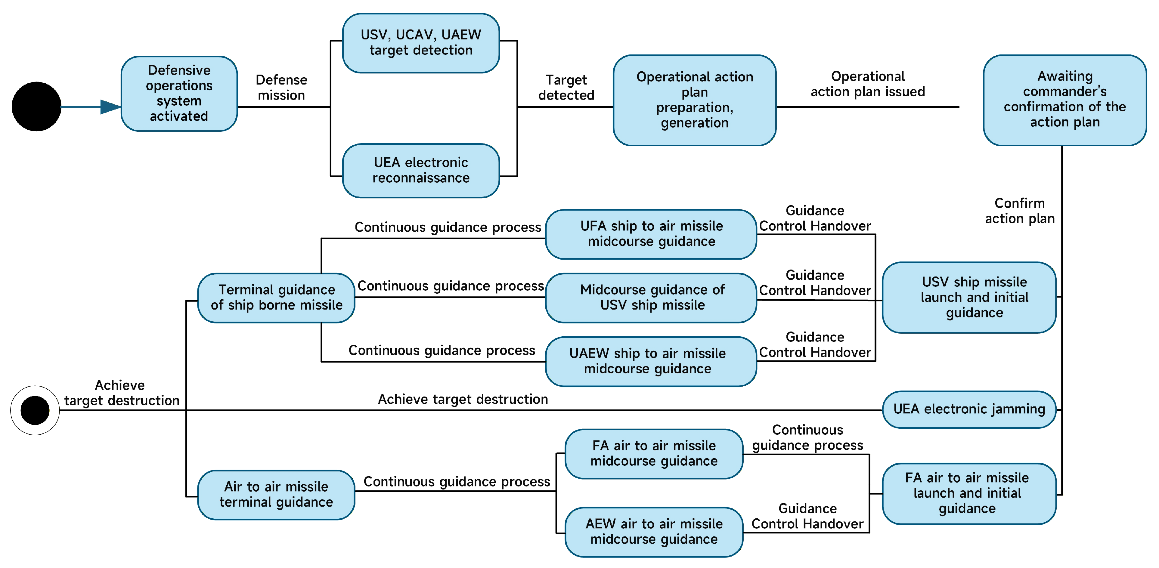
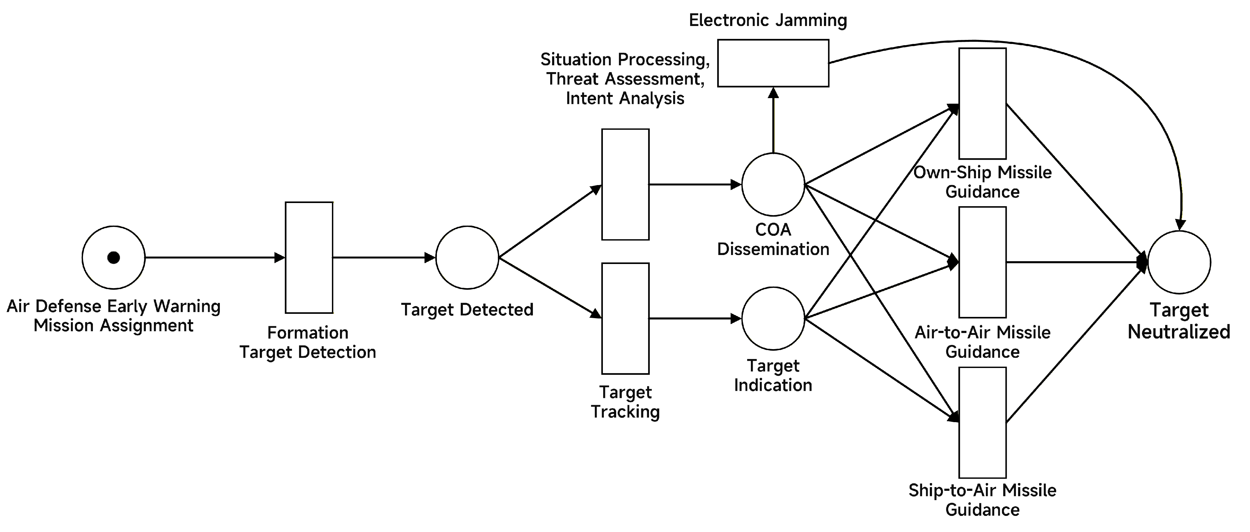
- The OV-6b State Transition Description Module. The OV-6b utilizes a graphical method to depict the evolution of mission states in response to diverse mission events, thereby clarifying the sequence of operational activities. As a complement to the OV-5b model, the OV-6b model constructed herein describes how the state transitions of the maritime formation anti-missile mission are driven by various mission events. Figure 8 illustrates the complete state transition process for the UAV-USV formation’s maritime defense and counterattack mission, delineating the entire sequence from target approach to target neutralization.
3.4. Decision-Making Workflow Method Based on Modules Driven by LLM
3.4.1. RAG Enhanced Situational Understanding and Decision Generation
3.4.2. Module-Based Model and Kill Chain Assessment
3.4.3. Comprehensive Decision-Making Report Generation
4. Experiment and Case Study
4.1. Mission Scenario
4.2. LLM Situational Understanding and View Modeling
4.3. Evaluation of Model Generation Accuracy
4.3.1. Comparative Evaluation of Tactical Instruction Generation
4.3.2. Ablation Study and Component Analysis
4.4. Static Analysis of Petri Net-Based Models
- Each Petri net model is safe and bounded;
- Every marking (state) in the Petri net model is reachable;
- Each Petri net model is live and deadlock-free.
4.5. Dynamic Model Testing
4.5.1. Temporal Consistency Analysis
4.5.2. Kill Chain Synergy Advantage Assessment
4.6. Model Completeness Check
4.7. Decision Making Under Uncertainty and System Robustness
4.7.1. Sensitivity Analysis of Decision Weights
4.7.2. Monte Carlo Convergence and Uncertainty Intervals
4.7.3. Failure Modes and Defense Mechanisms
- 1.
- Injection via corrupted sources. As a decision-support framework focused on specific domain, the DoDAF specification and the tactical doctrine database in RAG are physically isolated in offline, read-only storage. External situational input is strictly limited to parameterized standard data streams, effectively blocking malicious prompt injection and knowledge source pollution from the physical architecture.
- 2.
- Retrieval errors. The RAG module often retrieves mismatched tactical orders due to semantic offsets, leading the LLM to generate incorrect action mappings. However, this framework does not directly use the RAG output as the execution command; instead, it uses it as input to generate the OV-5b model. The model logic is verified using a Petri net verification module. Any behavior that violates tactical timing due to retrieval errors will trigger a deadlock or conflict error during the static verification phase, forcing the LLM to re-infer.
- 3.
- Schema-conforming but semantically wrong. During the experimental phase, we discovered that LLM can generate fake kill chains that perfectly conform to the JSON Schema but are tactically absurd. Static format validation cannot intercept such special hallucinations. At this point, the dynamic performance evaluation module serves as a filter. Such semantically flawed fake kill chains will be assigned extremely low anomalous performance scores () in the underlying simulation engine due to weapon mismatch or an extremely low probability of damage. They will be automatically eliminated from the scheme ranking and will not appear in the final recommendation.
- 4.
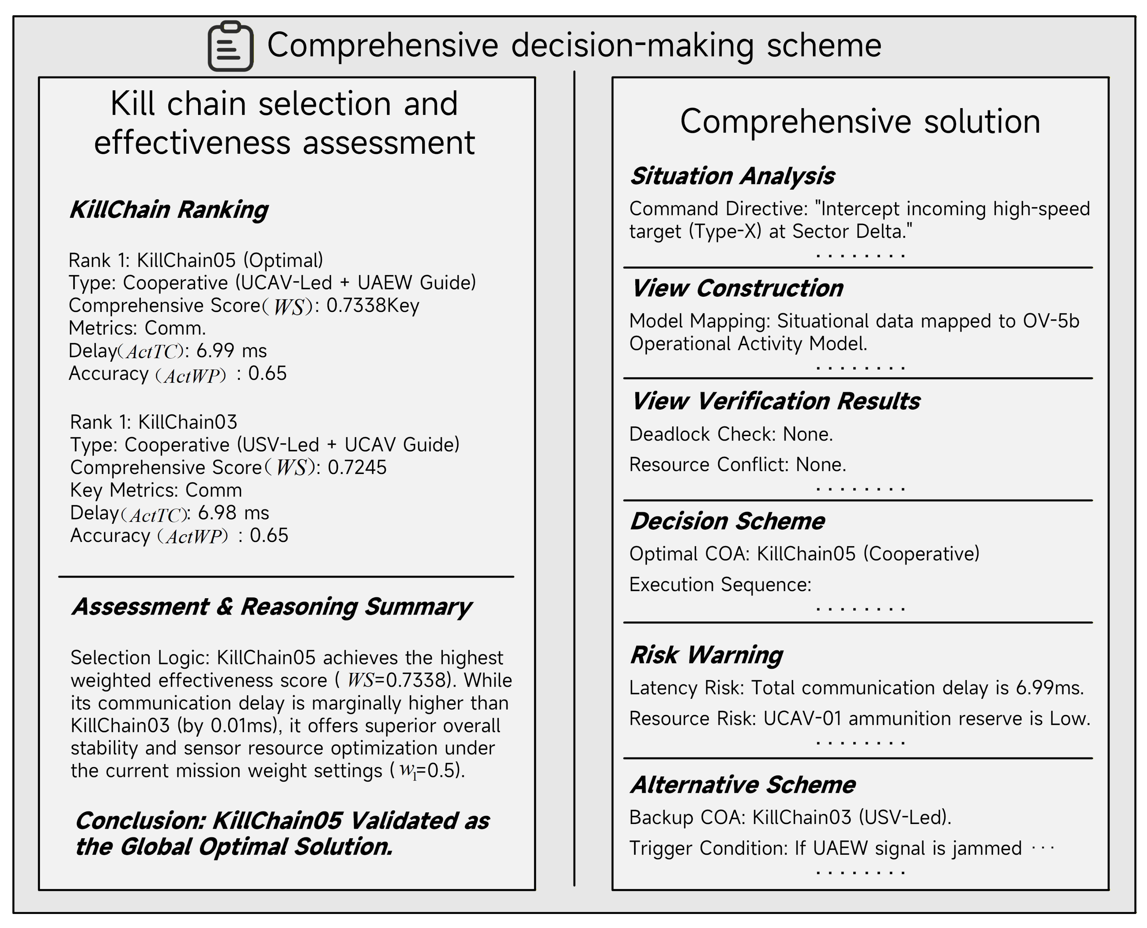
- Over-trust in generated recommendations. To prevent commanders from unquestioningly trusting system outputs under Automation Bias, this framework strictly adheres to a Human-in-the-loop design, as seen in the Commander Confirmed node in OV-6b. The system output is not automatically executed code, but rather a decision report containing a detailed reasoning trace. The report not only provides quantitative rankings but also explicitly lists resource consumption risks and alternative schemes, forcing commanders to obtain final human approval based on the chain of evidence.
5. Conclusions
6. Future Work
Author Contributions
Funding
Data Availability Statement
Conflicts of Interest
Abbreviations
| AI | Artificial Intelligence |
| API | Application Programming Interface |
| AV | All Viewpoint |
| C2 | Command and Control |
| COA | Course of Action |
| CV | Capability Viewpoint |
| DIV | Data and Information Viewpoint |
| DoDAF | Department of Defense Architecture Framework |
| FOC | Flight Ops Center |
| LLM | Large Language Model |
| MoDAF | Ministry of Defense Architectural Framework |
| OODA | Observe, Orient, Decide, Act |
| OV | Operational Viewpoint |
| PN | Petri Net |
| PV | Project Viewpoint |
| RAG | Retrieval-Augmented Generation |
| ROE | Rules of Engagement |
| SoS | System of Systems |
| StdV | Standards Viewpoint |
| SV | Systems Viewpoint |
| SvcV | Services Viewpoint |
| SysML | Systems Modeling Language |
| UAEW | Unmanned Airborne Early Warning |
| UAF | Unified Architecture Framework |
| UAV | Unmanned Aerial Vehicle |
| UCAV | Unmanned Combat Aerial Vehicle |
| UEA | Unmanned Electronic Attack |
| USV | Unmanned Surface Vehicle |
| WS | Weighted Score |
| XML | Extensible Markup Language |
Appendix A. System Instruction Specifications


References
- Bugarski, V.; Bačkalić, T.; Kanović, Ž. Fuzzy Decision Support System for Single-Chamber Ship Lock for Two Vessels. Appl. Syst. Innov. 2026, 9, 8. [Google Scholar] [CrossRef]
- Kureichik, V.; Danilchenko, V.; Bulyga, P.; Kartashov, O. Decision Support System for Wind Farm Maintenance Using Robotic Agents. Appl. Syst. Innov. 2025, 8, 190. [Google Scholar] [CrossRef]
- Luo, A.; Huang, L.; Luo, X. Research on activity-centric architecture methodology. Syst. Eng. Electron. 2008, 30, 499–502. (In Chinese) [Google Scholar] [CrossRef]
- Chen, C.; Zhang, X.; Yang, Z.; Zhou, H.; He, Q.; Han, C. Modeling and analysis approach for actual combat requirements of warships using department of defense architecture framework. Syst. Eng. Electron. 2025, 47, 3389–3400. [Google Scholar]
- Posherstnik, Y.; Rocksvald, E.R.; Lussier, B.; Makowski, M. Framework for Interoperable Command & Control of Joint Electromagnetic Spectrum Operations. In Proceedings of the 2019 IEEE Military Communications Conference (MILCOM), Norfolk, VA, USA, 12–14 November 2019; pp. 28–33. [Google Scholar] [CrossRef]
- Beery, P.; Irwin, T.; Paulo, E.; Pollman, A.; Porter, W.; Gillespie, S. Bridging Joint Operations and Engineering Management through an Operational Mission Architecture Framework. Eng. Manag. J. 2022, 34, 281–290. [Google Scholar] [CrossRef]
- Xu, C.C. Efficiency Assessment of a Joint Anti-Aircraft Carrier Combat System Based on MBSE. Master’s Thesis, Nanjing University of Aeronautics and Astronautics, Nanjing, China, 2022. (In Chinese) [Google Scholar] [CrossRef]
- Zhuo, Y. Research on System of Systems Modeling and Model Simulation Technology Based on Complex Scenarios. Master’s Thesis, University of Electronic Science and Technology of China, Chengdu, China, 2023. (In Chinese) [Google Scholar] [CrossRef]
- Zhao, T.; Gao, J.L.; Huang, J. Modeling and simulation of unmanned landing combat architecture based on DoDAF. Comput. Simul. 2023, 40, 46–54. (In Chinese) [Google Scholar] [CrossRef]
- Zhao, C.; Ou, Z.; Ye, J.; Wang, Y.; Li, Y. Architecture modeling of anti-UAV swarm combat system based on DoDAF. In Proceedings of the 11th China Command and Control Conference, Beijing, China, 20–22 October 2023; pp. 577–583. (In Chinese) [Google Scholar]
- Zhao, X.; Ren, T.; Fang, Z. Multi-model based iterative method for system-of-systems architecture design. J. Syst. Simul. 2025, 37, 15. (In Chinese) [Google Scholar] [CrossRef]
- Hause, M.; Kihlström, L.O. Using the security views in UAF. INCOSE Int. Symp. 2021, 31, 64–79. [Google Scholar] [CrossRef]
- Lu, Z.; He, S.; Du, J.; Ding, H.; Zhao, Q. Architecture modeling of carrier formation air defense and anti-missile combat based on UAF. Ship Electron. Eng. 2023, 43, 96–101. (In Chinese) [Google Scholar] [CrossRef]
- Dong, J. Research on Key Technologies of Architecture Modeling for Complex Scenarios. Master’s Thesis, University of Electronic Science and Technology of China, Chengdu, China, 2023. (In Chinese) [Google Scholar] [CrossRef]
- Martin, J.N.; Alvarez, K.E. Using the Unified Architecture Framework in support of mission engineering activities. In Proceedings of the 33rd Annual INCOSE International Symposium, Honolulu, HI, USA, 15–20 July 2023; pp. 1156–1172. [Google Scholar] [CrossRef]
- Wang, X.Y.; Cao, Y.F.; Sun, H.J.; Wei, C.S.; Tao, J. Modeling for cooperative combat system architecture of manned/unmanned aerial vehicle based on DoDAF. Syst. Eng. Electron. 2020, 42, 2265–2274. (In Chinese) [Google Scholar] [CrossRef]
- Huang, R.; Peng, Q.B.; Wu, X.F.; Ni, Q. Architecture modeling for manned lunar landing mission based on DoDAF. Syst. Eng. Electron. 2023, 45, 2131–2137. (In Chinese) [Google Scholar]
- U.S. Department of Defense. DoDAF-DOD Architecture Framework Version 2.02. Available online: https://dodcio.defense.gov/Library/Dod-Architecture-Framework/ (accessed on 1 December 2023).
- Wei, J.; Zhang, J.; Yang, W.; Ma, L.; Zhang, H. Architecture design of comprehensive disposal system for low, slow and small UAVs based on DoDAF. Syst. Eng. Electron. 2024, 46, 162–172. (In Chinese) [Google Scholar]
- Verdejo, D.; Laurent, E.M. How can LLM improve efficiency of C4ISR? In Artificial Intelligence for Global Security; Verdejo, D., Mercier-Laurent, E., Eds.; IFIP Advances in Information and Communication Technology; Springer: Cham, Switzerland, 2025; Volume 743, pp. 1–17. [Google Scholar] [CrossRef]
- Möbius, M.; Kallfass, D.; Flock, M.; Doll, T.; Kunde, D. Incorporation of military doctrines and objectives into an AI agent via natural language and reward in reinforcement learning. In Proceedings of the 2023 Winter Simulation Conference (WSC), San Antonio, TX, USA, 10–13 December 2023; pp. 2357–2367. [Google Scholar]
- Vladimír, V.; Jan, Z. The role of artificial intelligence in military. Chall. Natl. Def. Contemp. Geopolit. Situat. 2024, 1, CNDCGS’2024. [Google Scholar] [CrossRef]
- Topcu, T.G.; Husain, M.; Ofsa, M.; Wach, P. Trust at your own peril: A mixed methods exploration of the ability of large language models to generate expert-like systems engineering artifacts and a characterization of failure modes. Syst. Eng. 2025, 28, 583–604. [Google Scholar] [CrossRef]
- Ormo, H. System thinking in the design of enterprises with support of SEREA (Systems Engineering Reference Enterprise Architecture). INSIGHT 2025, 28, 24–31. [Google Scholar] [CrossRef]
- Wang, Y.; Bi, W.; Zhang, A.; Zhan, C. DoDAF-based civil aircraft MBSE development method. Syst. Eng. Electron. 2021, 43, 3579–3585. [Google Scholar] [CrossRef]
- Jung, H.; Kim, Y.-D.; Kim, Y. Maneuver-conditioned decision transformer for tactical in-flight decision-making. IEEE Robot. Autom. Lett. 2024, 9, 5322–5329. [Google Scholar] [CrossRef]
- Qi, X. Research on the Evaluation Methodology of Technology Contribution Degree to the Weapon System of Systems. Ph.D. Thesis, National University of Defense Technology, Changsha, China, 2015. Available online: https://kns.cnki.net/kcms2/article/abstract?v=Omth-A4cfW949aRYl4Gt_ZmW53lTMShViwWJwL4f9O8rBjiQRrVcpc3w_H0cEhSHw3Oj3QgDuUKiaeyYf-P24tTwdS_JDoNXDIq7nXuLwZ3eZgkpVKLwumt2t6KIgS3Kjmji9mb0lOC0a5Z8PfNTAHq9ntN1wIeyxP-iR1aKuB4OkHwi5ByOeeA2A6sNt8eF&uniplatform=NZKPT&language=CHS (accessed on 1 December 2023). (In Chinese)
- Luo, W.; Lei, G.; Zheng, X.; Lai, C.; Li, Y. Analysis of anti-missile efficiency of aircraft carrier formation under integrated combat. Sci. Technol. Eng. 2024, 24, 2706–2714. (In Chinese) [Google Scholar]
- Liu, Y.; Wang, Y.; Li, H.; Wang, G.; Ai, J. An adaptive operation planning and EBO-BPNN optimization method for decision support systems. Sci. Rep. 2024, 14, 21838. [Google Scholar] [CrossRef]
- Gong, S.; Chen, L.; Wang, Y. Analysis of U.S. Navy NIFC-CA system-of-system development and countermeasures. Telecommun. Eng. 2022, 62, 1859–1864. [Google Scholar] [CrossRef]
- Shi, Y.; Yang, R.; Liu, S.; Chen, Q.; Ding, X. Current status and insights on the development of US aircraft carrier strike group combat capabilities. In Proceedings of the 11th China Command and Control Conference, Beijing, China, 20–22 October 2023; pp. 161–165. (In Chinese) [Google Scholar]
- Pan, R.; Chen, J.; Wang, J.; Fang, Z. Intelligent modeling method of system architecture view based on large language model. Syst. Eng. Electron. 2025, 47, 3912–3923. [Google Scholar]
- Shen, Z.; Piao, C. Disposition of aircraft carrier formation based on operational action. Ship Sci. Technol. 2014, 36, 131–135. (In Chinese) [Google Scholar] [CrossRef]
- Chen, X.; Li, L. Research on U.S. aircraft carrier command system for antiaircraft and antimissile. Ship Sci. Technol. 2015, 37, 236–240. (In Chinese) [Google Scholar] [CrossRef]
- Rong, G.; Liu, X.; Xia, H. Operation architecture of air defense and anti-missile system of large warship formation based on DoDAF. Shipboard Electron. Countermeas. 2012, 35, 22–25, 39. [Google Scholar] [CrossRef]
- Zhao, T.; Liu, Y.; Ma, Y.; Cheng, Y.; Li, S. Modeling and simulation of target characterization architecture of target ammunition based on DoDAF. J. Syst. Simul. 2025, 1–13. [Google Scholar] [CrossRef]
- Wei, X.; Lou, Z.; Tu, Y.; Han, Y.; Pan, H. Research on kill chain analysis method of cooperative combat based on system of systems framework. Aero Weapon. 2025, 32, 31–39. [Google Scholar]




| All Viewpoint (AV) | Project Viewpoint (PV) | Data & Info Viewpoint (DIV) | Standards Viewpoint (StdV) |
|---|---|---|---|
| AV-1: Overview and Summary Information | PV-1: Project Portfolio Relationships | DIV-1: Conceptual Data Model | StdV-1: Standards Profile |
| AV-2: Integrated Dictionary | PV-2: Project Timelines | DIV-2: Logical Data Model | StdV-2: Standards Forecast |
| PV-3: Project to Capability Mapping | DIV-3: Physical Data Model | ||
| Capability Viewpoint (CV) | Services Viewpoint (SvcV) | Operational Viewpoint (OV) | Systems Viewpoint (SV) |
| CV-1: Vision | SvcV-1: Services Context Description | OV-1: High-Level Operational Concept Graphic | SV-1: Systems Interface Description |
| CV-2: Capability Taxonomy | SvcV-2: Services Resource Flow Description | OV-2: Operational Resource Flow Description | SV-2: Systems Resource Flow Description |
| CV-3: Capability Phasing | SvcV-3a: Systems-Services Matrix | OV-3: Operational Resource Flow Matrix | SV-3: Systems-Systems Matrix |
| CV-4: Capability Dependencies | SvcV-3b: Services-Services Matrix | OV-4: Organizational Relationships Chart | SV-4: Systems Functionality Description |
| CV-5: Capability to Organizational Development Mapping | SvcV-4: Services Functionality Description | OV-5a: Operational Activity Decomposition Tree | SV-5a: Op. Activity to Systems Functionality Traceability Matrix |
| CV-6: Capability to Operational Activities Mapping | SvcV-5: Operational Activity to Services Traceability | OV-5b: Operational Activity Model | SV-5b: Op. Activity to Systems Traceability Matrix |
| CV-7: Capability to Services Mapping | SvcV-6: Services Resource Flow Matrix | OV-6a: Operational Rules Model | SV-6: Systems Resource Flow Matrix |
| SvcV-7: Services Measures Matrix | OV-6b: State Transition Description | SV-7: Systems Measures Matrix | |
| SvcV-8: Services Evolution Description | OV-6c: Event-Trace Description | SV-8: Systems Evolution Description | |
| SvcV-9: Services Tech & Skills Forecast | SV-9: Systems Tech & Skills Forecast | ||
| SvcV-10a: Services Rules Model | SV-10a: Systems Rules Model | ||
| SvcV-10b: Services State Transition Description | SV-10b: Systems State Transition Description | ||
| SvcV-10c: Services Event-Trace Description | SV-10c: Systems Event-Trace Description |
| Category | Description |
|---|---|
| Background | To strengthen the UAV-USV formation defensive counterattack mission capability, the networked collaboration of C2 systems (auxiliary decision-making systems), sensor systems, interception systems, and electronic countermeasure systems is utilized. This achieves intelligent target threat assessment, formation mission analysis, and COA (Course of Action) generation, thereby completing the kill chain closed-loop and constructing a novel distributed, networked formation defensive counterattack mission system. |
| Objective | Centered on constructing UAV-USV collaborative kill chains, the objective is to maximize the utilization of sensor systems and interception systems within the formation, enhancing the formation’s situational awareness capabilities and improving the interception success rate against threat targets. |
| Constraints | The utilization of weaponry and equipment must strictly adhere to tactical rules and mission doctrines. Building upon intelligent decision support, it is also necessary to improve the efficiency and convenience of the interaction between the commander and the auxiliary decision-making system. |
| Models | Select relevant functional models under the All Viewpoint (AV), Capability Viewpoint (CV), Operational Viewpoint (OV) (referred to as Mission View), and Systems Viewpoint (SV). |
| Resource Flow ID | Resource Flow Type | Source Node | Target Node |
|---|---|---|---|
| SitnFlow01 | Situational Flow | UCAV | FOC |
| SitnFlow02 | Situational Flow | USV | FOC |
| SitnFlow03 | Situational Flow | UAEW | FOC |
| SitnFlow04 | Situational Flow | UEA | FOC |
| CtrlFlow01 | C2 Flow (Command & Control) | FOC | UCAV |
| CtrlFlow02 | C2 Flow | FOC | USV |
| CtrlFlow03 | C2 Flow | FOC | UAEW |
| CtrlFlow04 | C2 Flow | FOC | UEA |
| CtrlFlow05 | C2 Flow | UCAV | USV |
| CtrlFlow06 | C2 Flow | UAEW | USV |
| Type | Number of Formations | Units per Formation | Total Units |
|---|---|---|---|
| Flight Ops Center | 1 | 1 | 1 |
| USV Formation | 1 | 4 | 4 |
| UCAV Formation | 1 | 12 | 12 |
| UAEW Formation | 1 | 4 | 4 |
| UEA Formation | 1 | 4 | 4 |
| Type | Activity ID | Activity Description | Quantity |
|---|---|---|---|
| Command and Flight Ops Center | FOCAct01 | Situational Data Processing | 6 |
| FOCAct02 | Target Threat Assessment | ||
| FOCAct03 | Target Intent Identification | ||
| FOCAct04 | Formation Mission Analysis | ||
| FOCAct05 | COA Generation | ||
| FOCAct06 | COA Dissemination | ||
| USV Formation | USVAct01 | USV Target Detection | 6 |
| USVAct02 | USV Target Tracking | ||
| USVAct03 | Shipborne Missile Launch | ||
| USVAct04 | Shipborne Missile Initial Guidance | ||
| USVAct05 | Shipborne Missile Mid-course Guidance | ||
| USVAct06 | Shipborne Missile Terminal Guidance | ||
| UEA Formation | UEAAct01 | UEA Electronic Reconnaissance | 2 |
| UEAAct02 | UEA Electronic Jamming | ||
| UCAV Formation | UCAVAct01 | UCAV Target Detection | 7 |
| UCAVAct02 | UCAV Target Tracking | ||
| UCAVAct03 | Air-to-Air Missile Launch | ||
| UCAVAct04 | Air-to-Air Missile Initial Guidance | ||
| UCAVAct05 | Air-to-Air Missile Mid-course Guidance | ||
| UCAVAct06 | Air-to-Air Missile Terminal Guidance | ||
| UCAVAct07 | Shipborne Missile Mid-course Guidance | ||
| UAEW Formation | UAEWAct01 | UAEW Target Detection | 4 |
| UAEWAct02 | UAEW Target Tracking | ||
| UAEWAct03 | Shipborne Missile Mid-course Guidance | ||
| UAEWAct04 | Air-to-Air Missile Mid-course Guidance |
| Kill Chain ID | Kill Chain Sequence | Collaborative |
|---|---|---|
| KillChain01 | USVAct01 → USVAct02 → USVAct03 → USVAct04 → USVAct05 → USVAct06 → Target Neutralized | No |
| KillChain02 | UCAVAct01 → UCAVAct02 → UCAVAct03 → UCAVAct04 → UCAVAct05 → UCAVAct06 → Target Neutralized | No |
| KillChain03 | USVAct01 → USVAct02 → USVAct03 → USVAct04 → UCAVAct05 → USVAct06 → Target Neutralized | Yes |
| KillChain04 | USVAct01 → USVAct02 → USVAct03 → USVAct04 → UAEWAct03 → USVAct06 → Target Neutralized | Yes |
| KillChain05 | UCAVAct01 → UCAVAct02 → UCAVAct03 → UCAVAct04 → UAEWAct03 → UCAVAct06 → Target Neutralized | Yes |
| KillChain06 | UAEWAct01 → UAEWAct02 → USVAct03 → USVAct04 → USVAct05 → USVAct06 → Target Neutralized | Yes |
| KillChain07 | UAEWAct01 → UAEWAct02 → UCAVAct03 → UCAVAct04 → UCAVAct05 → UCAVAct06 → Target Neutralized | Yes |
| KillChain08 | UAEWAct01 → UAEWAct02 → USVAct03 → USVAct04 → UCAVAct07 → USVAct06 → Target Neutralized | Yes |
| KillChain09 | UAEWAct01 → UAEWAct02 → USVAct03 → USVAct04 → UAEWAct03 → USVAct06 → Target Neutralized | Yes |
| KillChain10 | UAEWAct01 → UAEWAct02 → UCAVAct03 → UCAVAct04 → UAEWAct04 → UCAVAct06 → Target Neutralized | Yes |
| Embedding | Chunk Strategy | Indexing Design | Retrieval Depth k | Context Window Budget | Failure- Handling Rules |
|---|---|---|---|---|---|
| BGE-Large- En-v1.5 | Chunk size: 512; Overlap: 64 | FAISS | 5 | 2048 tokens | Threshold < 0.65 |
| Element | Description |
|---|---|
| Places (P) | Represents mission resources, preconditions, or specific operational states (e.g., “Target Detected”, “Guidance Handover Ready”). |
| Transitions (T) | Directly corresponds to the operational activities defined in OV-5b (e.g., “USV Target Tracking”, “Missile Launch”). |
| Directed Arcs (F) | Maps to the control flows and data flows in OV-5b, defining the causal sequence between states and actions. |
| Tokens (M) | Represents the dynamic instantiation of mission events or the availability of resources. |
| Faction | Entity Object | Value Range | Generation Rules |
|---|---|---|---|
| Blue Force | Number of UCAV formations | Total combat aircraft: | |
| UCAVs per formation | Attack waves: | ||
| Missile payload per UCAV | Total incoming missiles: | ||
| Red Force | Number of USVs | Interception resource matching constraint: | |
| Number of Launch & Recovery Centers | Total interceptor capacity (USV + UCAV payload) must satisfy: | ||
| Number of UCAV formations | |||
| UCAVs per formation | To ensure meaningful confrontation, set threshold . | ||
| Number of UAEWs | Eliminate extreme invalid scenarios. |
| Scenario Type | Method | Entity Accuracy (%) | Logic Validity (%) | Format Compliance (%) |
|---|---|---|---|---|
| Simple Instruction | Qwen-8b | 94.5 | 86.8 | 81.2 |
| Ours | 99.5 | 99.0 | 100.0 | |
| Complex Multi-wave | Qwen-8b | 78.2 | 64.5 | 58.4 |
| Ours | 98.0 | 95.5 | 100.0 | |
| Multi-party Engagement | Qwen-8b | 54.6 | 38.2 | 45.5 |
| Ours | 92.4 | 89.2 | 100.0 | |
| Average | Qwen-8b | 75.8 | 63.2 | 61.7 |
| Ours | 96.6 | 94.6 | 100.0 |
| Method | Entity Accuracy (%) | Logic Validity (%) | Format Compliance (%) |
|---|---|---|---|
| Baseline (Qwen3-8B) | 75.8 | 63.2 | 61.7 |
| Baseline + RAG | 92.4 | 75.4 | 63.5 |
| Baseline + Schema | 74.1 | 62.8 | 100.0 |
| Baseline + Petri net | 76.2 | 88.5 | 62.0 |
| Baseline + RAG + Schema | 93.1 | 78.5 | 100.0 |
| Baseline + RAG + Petri net | 94.5 | 92.0 | 64.1 |
| Baseline + RAG + Schema + Petri net | 96.6 | 94.6 | 100.0 |
| Model Verification Metrics | Conflict Verification | Cycle Verification | Deadlock Verification |
|---|---|---|---|
| Verification Result | Interpretable conflicts exist | No cycles | No deadlocks |
| Parameter | Compliance Delay | Other Delay | Timeliness | Accuracy | Acquisition | Damage | Weight |
|---|---|---|---|---|---|---|---|
| Notation |
| Kill Chain Type | Average | Standard Deviation | Average Compliance Delay (ms) | |
|---|---|---|---|---|
| Non-cooperative Mode | 0.618 | 0.045 | 8.42 | 0.63 |
| Cooperative Mode | 0.752 | 0.018 | 6.98 | 0.84 |
| Kill Chain Type | Average Interception Rate | Interception Rate Range | 90% Confidence Interval (CI) | Effectiveness Degradation Rate |
|---|---|---|---|---|
| Non-cooperative | 0.625 | 0.438–0.705 | [0.608, 0.642] | 15.3% |
| Cooperative | 0.788 | 0.712–0.855 | [0.776, 0.800] | 4.1% |
| Operational Activity | Performer |
|---|---|
| Issuance of Defense Alert Mission | UAV Launch and Recovery Platform |
| Target Detection | USV Formation, UCAV Formation, UAEW Formation, UEA Formation |
| Target Tracking | USV Formation, UCAV Formation, UAEW Formation |
| Generation and Dissemination of COA | UAV Launch and Recovery Platform |
| Electronic Jamming | UEA Formation |
| Cooperative Missile Guidance Task 1 | UCAV Formation, UAEW Formation |
| Cooperative Missile Guidance Task 2 | UCAV Formation, UAEW Formation |
| Cooperative Missile Guidance Task 3 | USV Formation |
| Target Neutralization | USV Formation, UCAV Formation, UAEW Formation, UEA Formation |
Disclaimer/Publisher’s Note: The statements, opinions and data contained in all publications are solely those of the individual author(s) and contributor(s) and not of MDPI and/or the editor(s). MDPI and/or the editor(s) disclaim responsibility for any injury to people or property resulting from any ideas, methods, instructions or products referred to in the content. |
© 2026 by the authors. Published by MDPI on behalf of the International Institute of Knowledge Innovation and Invention. Licensee MDPI, Basel, Switzerland. This article is an open access article distributed under the terms and conditions of the Creative Commons Attribution (CC BY) license.
Share and Cite
Li, H.; Li, D.; Liu, Y.; Ma, J.; Wang, G.; Ai, J. LLM-Driven Modeling and Decision Support Methods for Cross-Domain Collaborative Mission Systems. Appl. Syst. Innov. 2026, 9, 80. https://doi.org/10.3390/asi9040080
Li H, Li D, Liu Y, Ma J, Wang G, Ai J. LLM-Driven Modeling and Decision Support Methods for Cross-Domain Collaborative Mission Systems. Applied System Innovation. 2026; 9(4):80. https://doi.org/10.3390/asi9040080
Chicago/Turabian StyleLi, Han, Dongji Li, Yunxiao Liu, Jinyu Ma, Guangyao Wang, and Jianliang Ai. 2026. "LLM-Driven Modeling and Decision Support Methods for Cross-Domain Collaborative Mission Systems" Applied System Innovation 9, no. 4: 80. https://doi.org/10.3390/asi9040080
APA StyleLi, H., Li, D., Liu, Y., Ma, J., Wang, G., & Ai, J. (2026). LLM-Driven Modeling and Decision Support Methods for Cross-Domain Collaborative Mission Systems. Applied System Innovation, 9(4), 80. https://doi.org/10.3390/asi9040080