1. Introduction
Motor impairments are commonly associated with various neurological disorders worldwide. These conditions often result from damage to brain cells (neurons), which, once injured, lose their ability to function and are unable to regenerate. The death of these neurons forces the surviving neurons to compensate by taking over the lost functions, a phenomenon known as neuroplasticity [
1,
2]. Physical rehabilitation is a widely used approach to support recovery in such cases, but traditional physical therapy presents several limitations. It often relies on the therapist to manually assist the patient’s movements, introducing inconsistencies due to human fatigue, variable range of motion, and difficulty maintaining uniform movement repetition, which can compromise therapy effectiveness.
To address these limitations, robot-assisted therapy has emerged as a promising alternative with a significant potential across multiple motor domains and anatomical regions [
3]. These systems leverage advanced actuator configurations and biomimetic structures to orchestrate complex, multi-joint movements with high precision. For example, Duanmu et al. [
4] developed a finger rehabilitation exoskeleton inspired by the ventral muscle arrangement of dragonfly abdomens, utilizing centre-tendon pneumatic bellows actuators to replicate natural flexion–extension kinematics. Similarly, Tian et al. [
5] designed an adaptive, cable-driven upper-limb exoskeleton modeled after the mechanics of a shrimp shell, achieving smooth elbow articulation through elastic sheath–cable coupling and real-time tension control, as well as the cable-driven exoskeleton developed by Chen et al. [
6]. This results in a massive and expensive construction that may not be easily affordable or practical for widespread implementation in settings like rehabilitation clinics or home use.
Beyond mechanical innovation, Sarhan et al. [
7] implemented an electroencephalography (EEG)-based control paradigm on a 3D-printed upper-limb exoskeleton for post-stroke rehabilitation, demonstrating that residual neural signals can be decoded to drive assistive motion even in the presence of cortical damage. These developments demonstrate how thoughtful design, intelligent actuation methods, and real-time neural feedback converge to make rehabilitation therapies more effective and engaging, particularly when wearable robotic systems guide patients through precise, repeatable movements with control over speed, range, and trajectory [
8,
9,
10,
11].
In parallel, the use of electromyographic (EMG) and EEG signals in rehabilitation has received increasing attention, as they provide rich physiological and neural information. As Al-Quraishi [
12] note, when analyzed properly, these biosignals can offer real-time insights into a patient’s physiological status and mental condition. Through advanced signal processing, raw physiological signals can be transformed into meaningful information, enabling adaptive, targeted, patient-centered therapy [
13]. Neural feedback can enhance responsiveness and adapt therapy in real time to the patient’s affective and cognitive state, leading to highly personalized recovery experiences [
14]. Steady progress in robotic exoskeleton development has expanded rehabilitation possibilities, aligning assistive technology more closely with individual patient needs and addressing challenges in restoring motor function. Brain–Computer Interface (BCI) technology is increasingly being integrated into these systems, augmenting user engagement and informing therapy protocols [
15]. Despite challenges in assessing patient participation, combining BCI and robot-assisted therapy shows promise for improving motivation, effectiveness, and quality of life [
16].
Relaxation, the ability to achieve and maintain mental and physical calm, is essential for recovery, emotional regulation, and cognitive performance. However, this ability can be compromised by several factors, such as environmental stressors, accumulated psychological stress, or neurological disorders such as stroke, where this can directly affect and make it more difficult for people to achieve a relaxed state [
17]. Stroke, caused by blockage or rupture of cerebral blood vessels [
18,
19,
20], often leads to hemiplegia, aphasia, and sensory disturbances [
21,
22], with over 70% of survivors experiencing motor impairments and around 40% facing moderate to severe long-term disabilities [
23]. Given these challenges, robotic systems for motor rehabilitation, especially EEG-based upper-limb exoskeletons, have emerged as a growing technological field [
24]. The main objective of this study is to design, implement, and evaluate a brain–computer interface (BCI) framework based on EEG signals, specifically alpha-band modulation and voluntary eye-blink detection, to control a rehabilitation exoskeleton in a manner that is adaptive, user-centric, and suitable for integration into both clinical and home-based therapy. The proposed system seeks to enhance patient engagement, reduce emotional barriers such as stress and anxiety, and improve motor rehabilitation outcomes through personalized calibration and multimodal monitoring. Our central hypothesis is that an EEG-driven exoskeleton, when combined with individualized thresholding for alpha-band and eye-blink detection, can reliably discriminate intentional control commands from background neurophysiological activity, thereby enabling accurate and robust interaction even in non-invasive and low-cost setups. We further hypothesize that such an approach can provide a scalable and clinically relevant tool for neurorehabilitation, potentially extending its applicability to diverse patient populations, including post-stroke and neurodegenerative conditions.
The exoskeleton system uses a specially designed Python™ signal processing application to identify alpha wavebands in EEG signals. When alpha activity is detected, a progress bar that graphically depicts the current selection state is activated by a graphical user interface (GUI). When the system detects a voluntary eye blink using the same EEG signal stream, it cycles to the next selectable option and begins the alpha wave detection process anew. This system response enables intuitive, hands-free navigation through the control interface in a non-invasive manner. Through a planetary gear motor built into the elbow joint, the exoskeleton begins to move once a selection is verified as matching one of the preset velocity parameters. For position control, the motor uses a sinusoidal input, which contributes to steady and fluid arm movement. A rotary incremental encoder measures the angle of the arm, which the system progressively increases during flexion to about 130°. After reaching this point, the motor smoothly switches directions to start the extension phase, maintaining the same sinusoidal pattern throughout the cycle. This mechanism facilitates a natural and continuous range of motion during therapy sessions, allowing for a seamless experience. The selectable options navigated via alpha wave activity and blink detection correspond to the velocity settings of the rehabilitation exercise. Additionally, the system is also equipped with a Brain-Computer Interface (BCI), providing patients with the opportunity to play an active part in treatment.
2. Materials and Methods
2.1. System Configuration and Design
To ensure both efficient performance and user safety, the exoskeleton was developed through a series of clearly defined stages using an organized engineering methodology:
Functional and Technical Requirements: Gather clinical and user needs through extensive research, expert interviews, and stakeholder workshops. Define system specifications (range of motion, payload, safety limits), meet the applicable regulatory standards (ISO 13485 [
25]; IEC 60601 [
26]), and performance metrics (accuracy, repeatability, latency).
Elbow Joint Biomechanical Study: Perform a biomechanical analysis of the elbow. Quantify physiological range of motion, joint torque profiles, and muscle activation patterns to establish mechanical constraints and actuator requirements (torque, weight, dimension).
Ergonomic Design: Create CAD models and run finite-element simulations to optimize link geometry, joint alignment, and load distribution. Ensure user comfort via adjustable velcro straps, padding placement, and weight minimization while preserving structural rigidity.
Material Selection: Materials are to be chosen to minimize skin irritation, reduce the risk of adverse reactions, and lower the burden of ongoing maintenance, all of which contribute to safer and more comfortable long-term use in therapeutic settings.
Prototype Manufacturing: Use of additive manufacturing, such as 3D printing, for complex geometries. Conduct dimensional verification and surface finish inspections before assembly.
Actuation System: Select the ideal motor and matching driver to meet torque and speed requirements. Design and fabricate a stationary module to secure the motor, and integrate limit switches and emergency stop mechanisms for safety protocols.
Sensors Integration: Integrate a 6000 PPR rotary incremental encoder for high-resolution angle feedback and two mechanical limit switches to define physical endpoints for flexion and extension. Calibrate all sensors and verify signal integrity under dynamic loading.
EEG Acquisition System: Deploy the UltraCortex Mark IV headset with electrodes collocated according to the 10–20 system (O1, O2, P3, P4, Fp1, Fp2). Configure OpenBCI firmware for real-time streaming, and establish data buffering and artifact rejection routines in Python™.
Signal Processing: Execute Butterworth bandpass filters and wavelet denoising to isolate the alpha band (8–13 Hz) and the blinking artifacts (4–20 Hz). Develop an independent detection to determine the action related to the exoskeleton system. Validate algorithm performance during EEG test sessions.
Design and Implementation of the PD Controller: Create a simulation with specialized software and confirm the efficacy of the control. On the selected microcontroller, execute the PD algorithm, making sure that a control loop frequency is reached, and put safe soft-start and stop procedures in place.
Graphical User Interface Development: Develop a cross-platform GUI that displays a progress bar for selection and system status. Integrate blink-driven navigation and command confirmation.
Control Experiments and Iterative Optimization: Design bench-top and human-in-the-loop tests to assess tracking accuracy, response latency, and user comfort. Analyze results to refine mechanical tolerances, adjust controller parameters, and improve signal-processing thresholds.
Custom PCB Design: Lay out a compact PCB to host the microcontroller, driver, and sensor interfaces. Perform routing optimization for low EMI, including test points, and fabricate through a rapid-turn PCB service.
System Validation and Documentation: Use healthy volunteers and, if possible, volunteers with upper limb motor impairments to validate the system. Verify compliance with safety and performance requirements. For knowledge transfer and regulatory submission, draft a user manual, maintenance guide, and final report.
2.2. Development of Mechanical Design
The elbow joint’s physiological range of motion was thoroughly examined in order to create the mechanical design of the suggested exoskeleton. This required a thorough examination of the upper limb’s anatomy and biomechanics, with a focus on the muscles that control elbow flexion and extension. Although the upper limb presents complex articulation, especially at the wrist and hand, the present study focuses exclusively on the elbow joint. By disregarding pronation/supination and internal/external rotation, the elbow is considered a single-degree-of-freedom (1-DoF) joint, responsible for flexion and extension movements. The design was therefore optimized to accommodate this single axis of motion, ensuring safe and effective rehabilitation performance within physiological limits. The angular range and associated muscular activation for elbow flexion and extension are shown in
Table 1. These parameters were essential for defining both the mechanical stops of the system and the motion profile programmed into the actuator [
27].
This information guided the mechanical and control design of the exoskeleton so that it is suitable for operation within the safe biomechanical limits of the human elbow, thereby reducing the risk of overextension or injury during rehabilitation therapy.
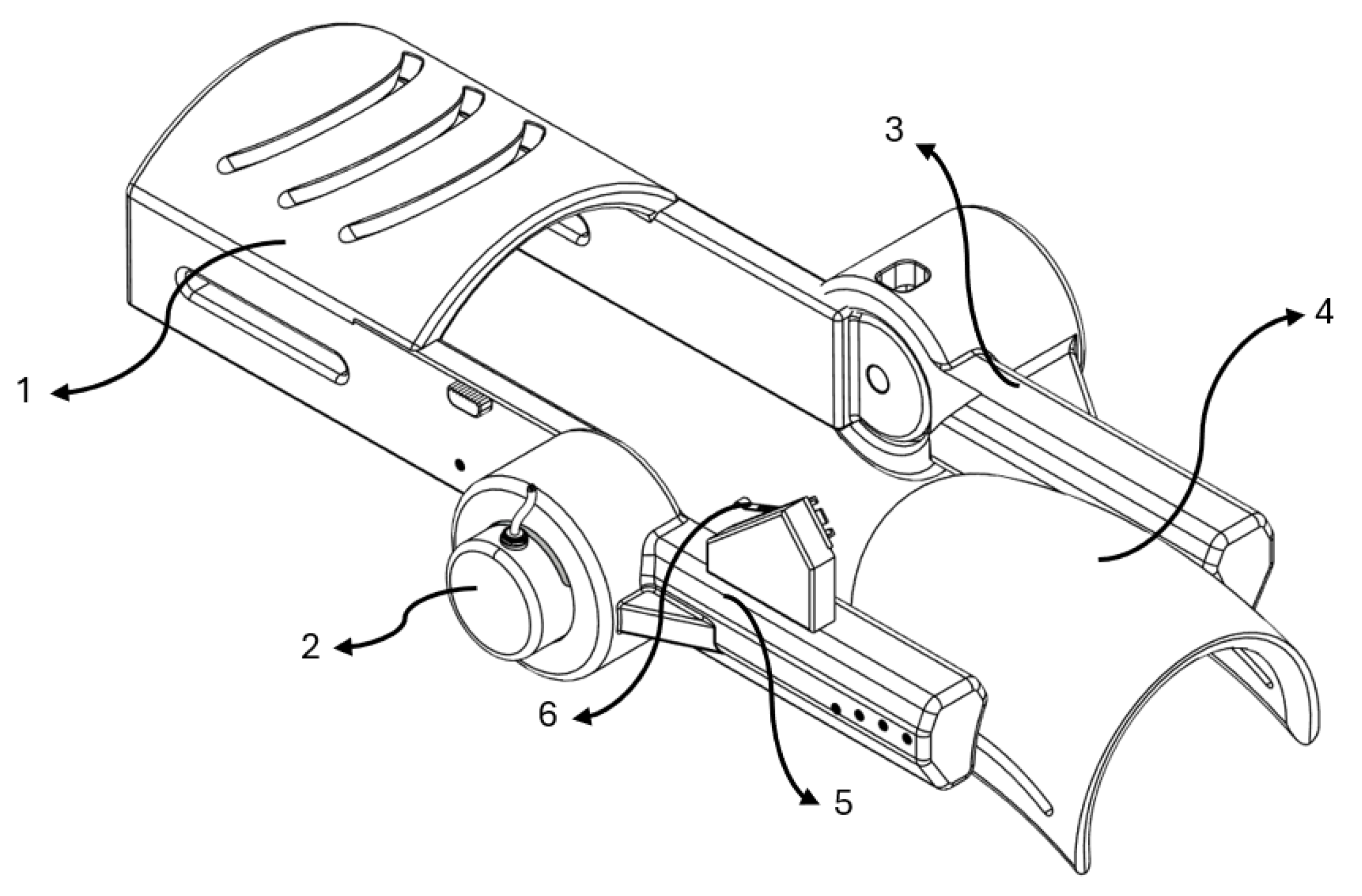
The result of the designed wearable prototype is represented in
Figure 1.
The main components of this mechanical system are:
Solid section for forearm positioning.
Incremental encoder mounted at the elbow joint.
Assembled link coupled to the planetary gear stepper motor.
Solid section for biceps positioning.
Assembled link coupled to the incremental encoder.
Stop end strategically located to define the upper angular limit.
A planetary gear stepper motor (model 17HS2408S-HG) was selected due to its ability to deliver sufficient torque to counteract the resistance generated by upper limb movements. A stationary module was designed to keep the motor fixed to allow proper functionality, enabling the exoskeleton to actuate only the segment intended to facilitate elbow joint movement. Given the use of a stepper motor coupled with a planetary reduction gearbox, an appropriate motor driver was also selected to enable the implementation of precise control strategies. This configuration allows for accurate regulation of the motor’s angular position, essential for achieving smooth and repeatable flexion-extension movements during rehabilitation sessions.
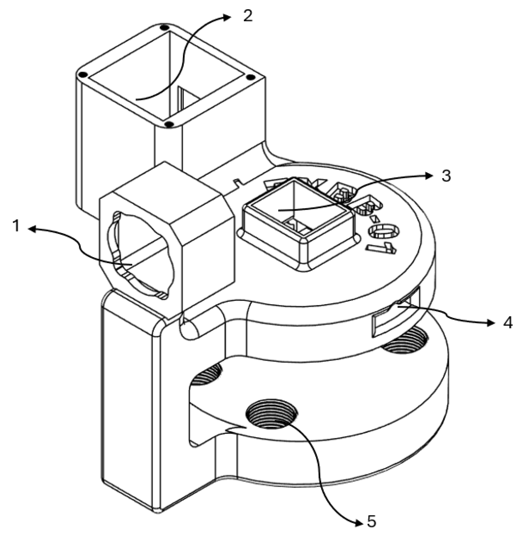
Figure 2 shows the stationary module computer-assisted design.
The stationary module incorporates a key structure designed to integrate specific components. Its functions can be summarized as follows:
Housing for motor positioning.
Mounting area for cables and coupling of the TFT display.
Mounting area for the emergency stop button.
Pass-through channels for cable routing.
Clamping section with 3D-printed screws to apply pressure between the module and the therapy table, securing its position.
Besides the fundamental electromechanical components, several other auxiliary parts have been incorporated to improve system performance and for operational safety. This includes an emergency stop button, a 6000 PPR encoder for angular position feedback, two mechanical limit switches for controlling travel limits, and a 1.8-inch TFT ISP display for live interaction and system status visualization.
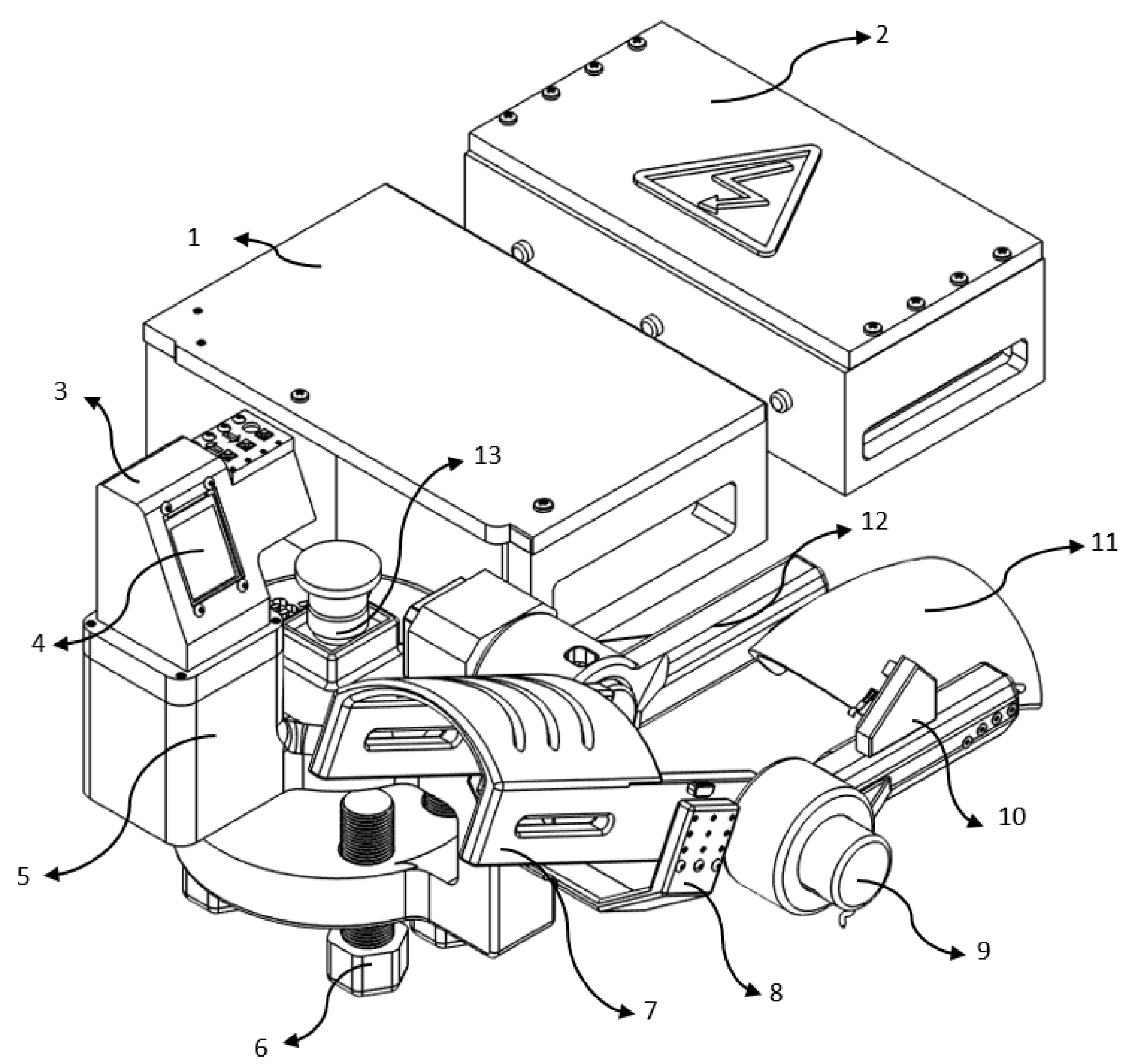
Figure 3, describes the various components below.
The following elements were used to construct the prototype system:
Controller and motor driver housing: Provides electrical integration and physical protection to the microcontroller unit (MCU) and stepper motor driver.
Power supply enclosure: Houses the DC power source that supplies the MCU and actuation systems.
TFT display shell: Can fit to support and protect the TFT screen and input buttons for manual control.
TFT control display: Manual operation of the GUI screen for therapy selection.
Fixed base unit: Provides mechanical support and maintains the system’s stability.
3D printed screws: Lock in the module to prevent any unwanted fetching during work.
One Piece Forearm Section: The 3D printed piece that connects and supports the patient’s forearm during therapy.
Arm holder: Exerting a slight pressure to hold the arm, preventing accidental falling by gravity.
6000 PPR encoder: High-resolution 6000 PPR encoder enables precise control of angular locality and necessary boundaries to closed-loop control.
Support for encoder link: Links encoder to the biceps portion, keeping it in place and orientation.
Biceps section: It supports the upper arm and contains the exoskeleton links which align it when it moves.
Joint link (biceps to rotor): Transmits torque from the actuator to generate the required flexion-extension motion.
Emergency stop button: Enables immediate system shutdown in case of emergency or abnormal operation.
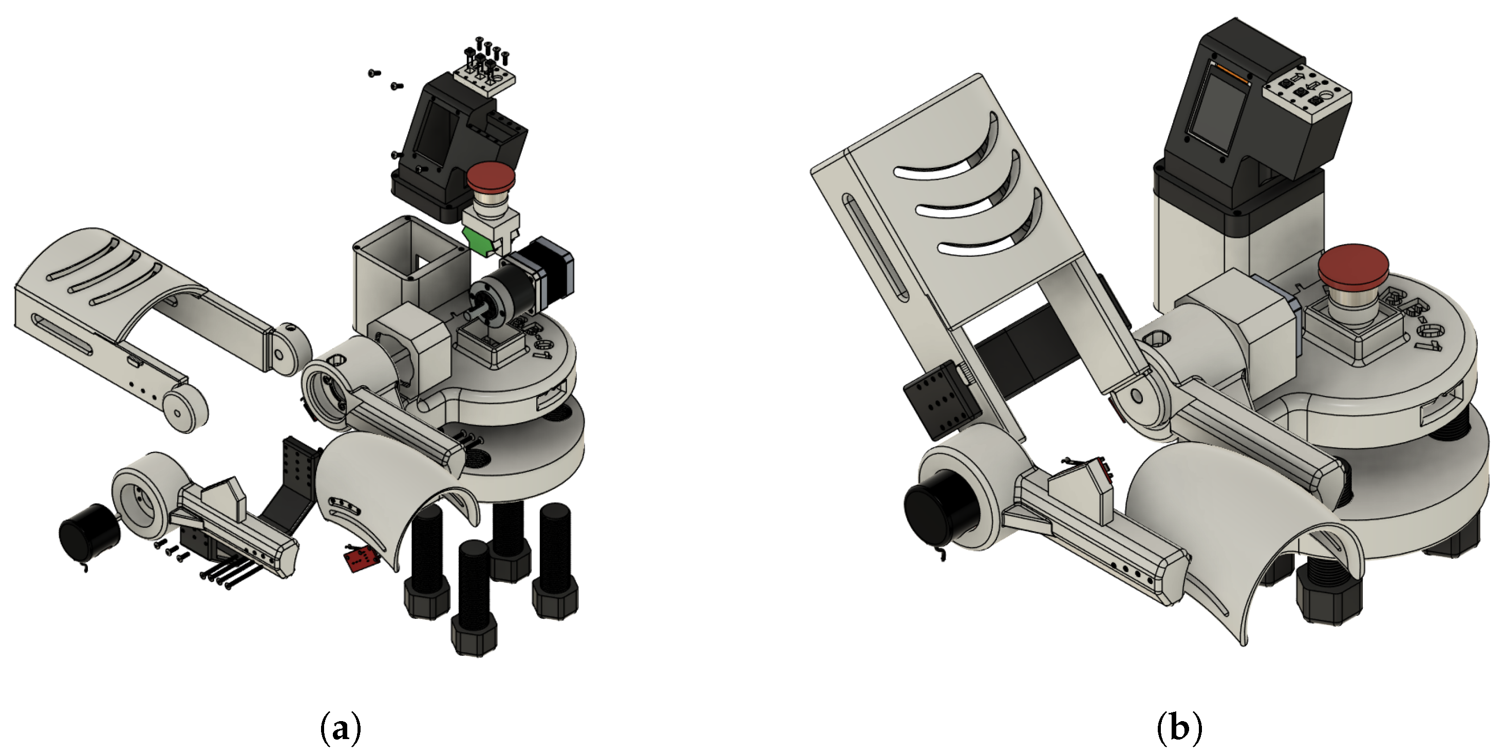
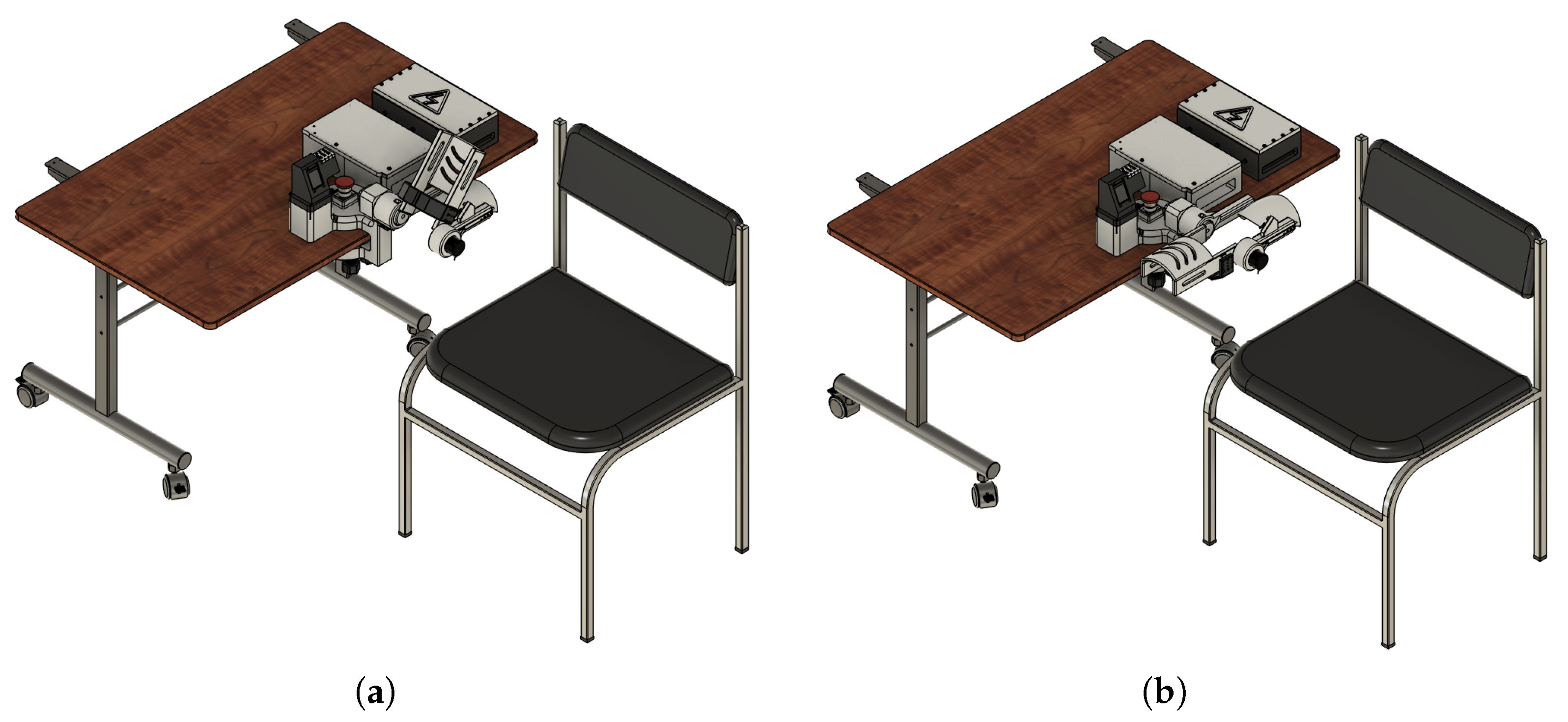
Figure 4a,b show the mechanical design of the proposed system excluding the section dedicated to the control unit, the driver for the motor control, and the power supply module.
The rehabilitation mechanism is actuated to guide the upper limb through a physiologically relevant range of motion, supporting neuromuscular reeducation during therapy sessions. The system has been configured to operate within a movement range from 0° (full extension) to approximately 130° (maximum flexion), which validates the operation under the standard therapeutic recommendations. This operational range has been validated through motion simulation studies and the help of experts in the field of study.
Figure 5 illustrates the exoskeleton in its two extreme positions: full flexion (
Figure 5a) and full extension (
Figure 5b). These images also include the stationary support modules for motor driving, system control, and power supply, which are integrated into the system’s base to grant mechanical stability and minimize dynamic loads on the user’s limb.
This user setup encourages the device’s use in controlled settings, like research labs or clinical rehabilitation centers, where stationary operation is preferred for ease of supervision and safety.
2.3. Development of the Automatic Control
2.3.1. Development of the Dynamic Model
The dynamic model of a single link was derived using the Euler–Lagrange method. The system parameters are defined in
Table 2.
First, the forward kinematics of the link’s center of mass were obtained as:
Next, the kinetic energy
of the system was computed using:
where the linear velocity
v satisfies:
Substituting the expressions for
and
yields:
Thus, the kinetic energy becomes:
The potential energy
is given by:
where the height
h of the center of mass relative to the reference is:
therefore,
The Lagrangian
is then:
Finally, applying the Euler–Lagrange equation,
we compute:
Thus, the dynamic equation for the motor torque is:
The numerical simulation of this dynamic model was performed using parameters derived from the exoskeleton design. The moment of inertia
I was obtained from the CAD model’s inertia tensor and the material density. The link mass
m was set based on the average adult forearm weight (1.4–1.8 kg) [
28,
29]. These static data were used to check the torque demands and system response in the simulation.
2.3.2. Automatic Control System
Automatic control plays a key role in achieving precise and repeatable motion of the device, ensuring safety within established ranges and smooth operation along the desired trajectory. The dynamic behavior of the system can be described by differential equations, and over the last five decades, a broad range of control strategies has been developed to address different control objectives such as position regulation, velocity tracking, or force control. In recent years, advanced control approaches have been successfully applied in diverse engineering domains, including nuclear reactor regulation [
30], renewable energy systems [
31], and nonlinear process control [
32], demonstrating high performance in complex, nonlinear, and uncertain environments. Although these sophisticated controllers offer excellent capabilities, they typically require detailed plant modeling, significant computational resources, and extensive tuning efforts. Since the primary control objective is angular position regulation, high computational power is not required. Adequate performance with high precision and low steady-state error can be achieved using simpler control strategies. For the present work, a Proportional–Derivative (PD) controller was selected due to its simplicity, robustness, and efficiency in position tracking, making it well-suited for real-time implementation on embedded systems with limited computational capacity.
The input movement trajectory was created through an internal sinusoidal signal created with the microcontroller to perform the motion reference input, simulating the movement of the elbow, in a physiological range approximately 0° to 130°. This signal is the reference input that enables the repetitive smooth motion suitable for rehabilitation exercises.
In order to close the loop on the system, the angles of the joints are read out in real-time by a 6000 PPR rotary encoder with high-resolution feedback. This error in attitude is converted into degrees and compared to the reference trajectory to determine the position error.
The control signal is processed with the following equation by the PD controller:
where:
is the control signal applied to the motor (i.e., speed command).
is the instantaneous position error.
is the derivative (rate of change) of the error.
is the proportional gain.
is the derivative gain.
This control signal is limited within predefined saturation bounds to prevent unsafe actuation and protect both the hardware and the user.
The motor actuation is managed through a stepper motor driver (DM542T), where the computed control signal directly influences the rotation speed. The controller works at a sampling interval set by a timer with microsecond accuracy. This approach ensures that control updates happen consistently and on time. A hardware emergency stop mechanism is in place to stop all motion if unsafe conditions arise. When this mechanism activates, visual indicators let the user know the system’s status, and the controller switches to a safe idle state. This PD-based control system lets the exoskeleton follow the desired joint path accurately. It does this even in dynamic conditions or when there are outside disruptions. The system also ensures that the user stays safe and comfortable.
2.4. Design of the Electronic Circuit
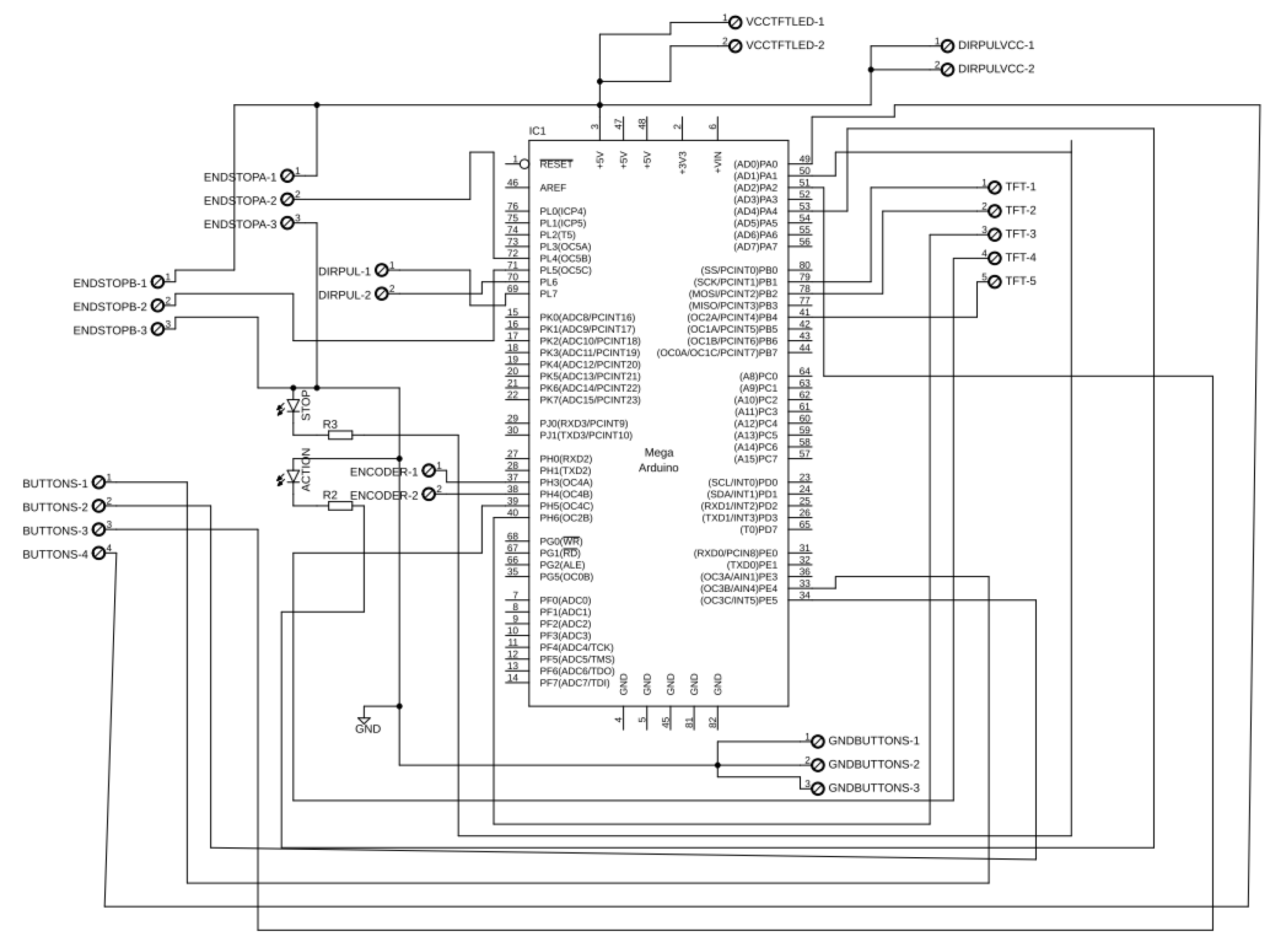
To help integrate and organize the components in the EEG-controlled exoskeleton system, we developed a custom-designed Arduino Shield shown in
Figure 6. This shield fits directly onto the Arduino Mega 2560. It combines all the necessary electrical connections into a compact and easy-to-use design. The goal was to simplify the development process, cut down on wiring issues, and reduce the chances of connection errors. This method increases the system’s reliability for both experimental setups and possible clinical use.
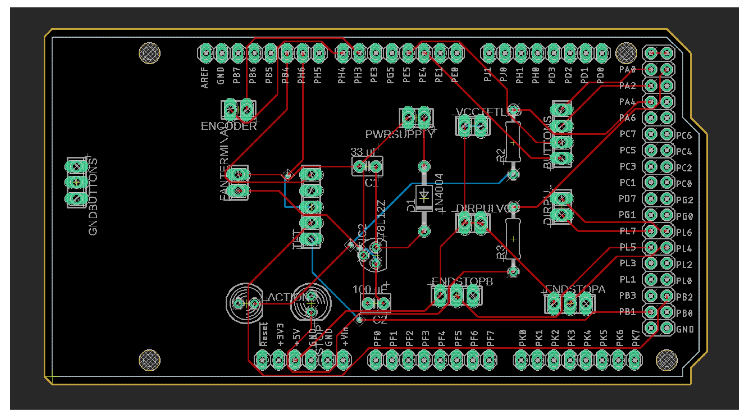
The hardware consists of a two-layer PCB, depicted in
Figure 7. The layout is efficient and provides great routing for signals and power. There are connectors and headers that facilitate the alignment of peripheral modules such as sensors, actuators, and communication interfaces. The modular design also offers accessory storage and simplifies clean-up and reconfiguration. It supports rapid prototyping and adaptation to various rehabilitation scenarios as well.
With the integration architecture optimized with custom hardware, the system attains more scalability and is ready for real-time implementation in a physical rehabilitation environment. This implementation further improves the reproducibility of the setup, which is important for future studies and broader development in the field of assistive technologies controlled by EEG.
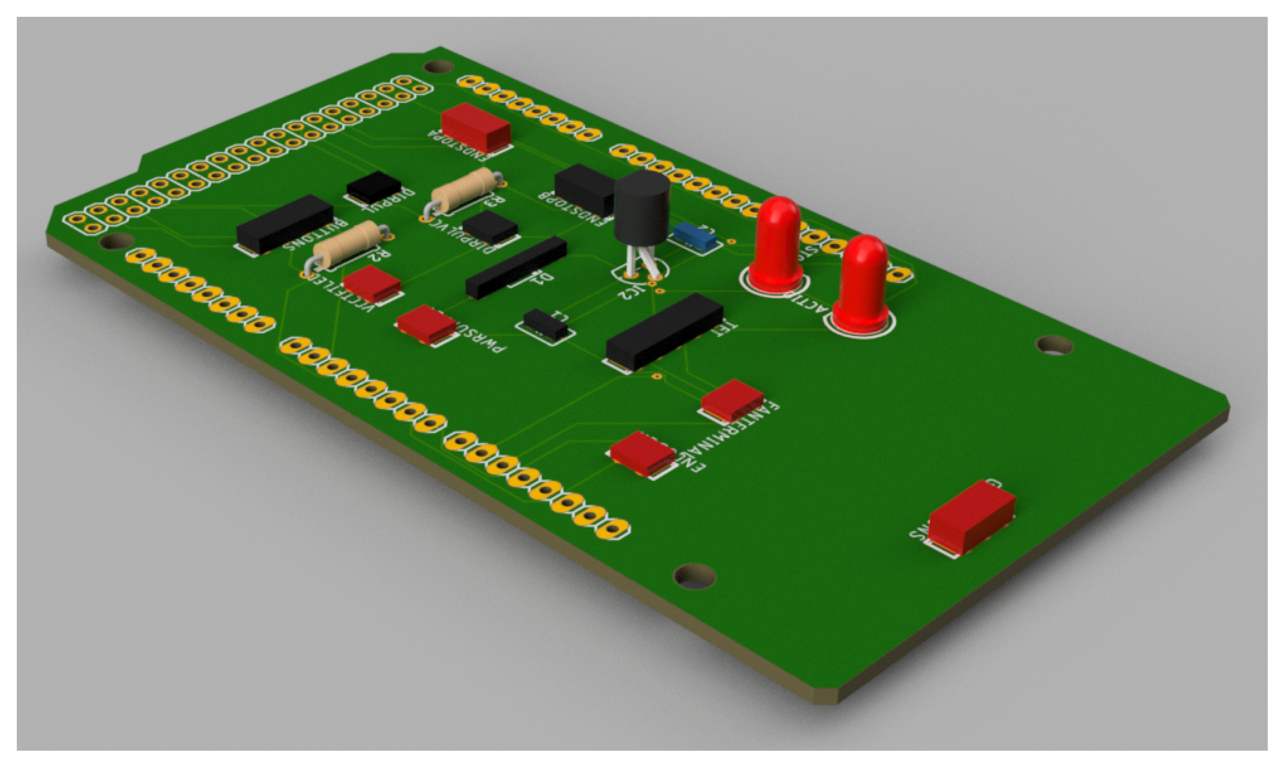
The ultimate fabrication of the circuit is designed to be close to the computer-aided design (CAD) model shown in
Figure 8. This model also gives a visual outlook of the design towards the layout of the board and depicts how the components will be arranged and the total size of the embedded system interface.
A custom PCB shield is employed, which minimizes prototyping time and provides a reproducible and standardized hardware platform for further research or clinical translation. This is of particular importance in rehabilitation facilities where reliability, safety, and integration simplicity are pivotal for the safety of the system and usability for the patient.
2.5. Signal Processing Applied to the Detection of Alpha Wavebands
The EEG signal processing system was developed to identify movement-related alpha activity and cognitive-related alpha activity [
33], in order to provide control for the exoskeleton for elbow rehabilitation. The detection process includes two steps: the training process and the online checking process. In each of these, the system implements a certain sequence of signal processing operations:
Collection of the raw EEG data for four channels including O1, O2, P3 and P4.
Application of a notch filter (from 0.5 to 60 Hz) to eliminate power line interference.
Temporal segmentation of the signal into fixed-length windows.
Noise reduction using wavelet denoising techniques to preserve relevant frequency components.
Bandpass filter using an 8–13 Hz Butterworth filter to isolate alpha waveband frequencies.
Transformation of the signal to the frequency domain using the Fast Fourier Transform (FFT).
Numerical integration of the frequency spectrum using the trapezoidal rule to estimate power spectral density.
Signal thresholding based on statistical metrics: mean area under the curve () and standard deviation () calculated during training.
EEG signals were acquired using the
OpenBCI® platform (Brooklyn, NY, USA). The 8-channel Cyton
® biosensing board was used with the UltraCortex Mark IV
® headset. This headset follows the international 10–20 system for electrode placement, which ensures consistent and standard positioning. This consistency is important for getting reliable and high-quality neural recordings. In order to explore the alpha activity, the data were analyzed based on signals from the parieto-occipital electrodes (O1, O2, P3, and P4). These regions are also known in the literature to exhibit high alpha rhythm activity, particularly in the resting state with closed eyes [
34,
35,
36]. Frontal electrodes Fp1 and Fp2 were used only to record eye blinks, since these are sensitive to electrical activity from the muscles surrounding the eyes, causing an EEG spike response when blinking.
2.5.1. EEG Signal Mean Acquisition
For the purpose of simplifying the analysis and improving the SNR (signal-to-noise ratio), the signal for alpha wave band detection was obtained by averaging the signals from the four electrodes. It is well known from the literature that spatial averaging serves as an effective technique for preserving significant frequency content and diminishing the local noise and channel variations [
37]. This is achieved by reflecting the data into a lower dimension that respects the similarity with nearby channels, and minimizes the instability and unreliability of power spectral estimates in the alpha band (8–13 Hz). This is crucial in those applications that involve estimating cognitive states and operating a BCI. The average
sample is calculated as follows:
The following are given:
represents the mean of all signals at the k-th sample.
represents the value of the i-th signal at the k-th sample, for .
M is the total number of signals (here, ).
N is the total number of samples.
By applying this method, the vector
is obtained, as shown below:
2.5.2. Notch Filtering
When raw EGG signals are acquired, those signals are inherently low-amplitude and highly susceptible to various sources of noise and artifacts, among which power line interference (PLI) is one of the most pervasive. Typically originating from the 50 Hz or 60 Hz frequency of electrical power systems, PLI introduces a persistent sinusoidal component into the EEG recording that can significantly degrade signal quality and obscure neurophysiological features of interest, particularly in spectral bands close to the interference frequency.
To mitigate this problem, a digital notch filter is often applied. A notch filter, also called a band-stop filter with a very narrow stop band, is designed to attenuate a specific frequency while leaving the remainder of the frequency spectrum largely unaffected. In this study, an Infinite Impulse Response (IIR) notch filter was applied to remove the PLI from the EEG recordings [
38]. IIR filters work well for this task because they are efficient and can achieve sharp frequency reduction with a low filter order. This feature is very important for real-time EEG applications. It decreases the noise to a dose-specific interferent of 60 Hz. It also preserves near-frequency components similarly. These may include further physiological information, such as the alpha band (8–13 Hz).
In contrast to larger notch band-stop or high-pass filters, the notch filter may cause minimal signal distortion. It maintains the timing and frequency precision of the EEG signal.
Mathematically, the frequency response of an ideal notch filter is given by
where
denotes the center frequency at which the attenuation is maximum.
An IIR digital notch filter of second order is often used due to its efficiency and sharp frequency rejection, which has a low computational cost to implement in practice. The corresponding transfer function in the z-domain is given by:
In this expression, the numerator defines the filter zeros placed on the unit circle at , and the denominator defines the poles inside the unit circle at radius to ensure stability. The poles and zeros are symmetrically distributed around the unit circle to preserve the real-valued nature of the filter coefficients.
Using Euler’s formula,
, the transfer function can be reformulated into a real-coefficient expression:
This representation is particularly useful for digital implementation using difference equations. Accordingly, the linear time-invariant difference equation corresponding to this filter is:
In this case,
is the output signal and
is the discrete-time input signal. Because of its ability to compute the filtered signal recursively, this formulation is appropriate for real-time EEG processing applications. In its canonical form, the generalized transfer function of a digital IIR filter is as follows:
where
and
are the feedforward and feedback coefficients, respectively, and
N denotes the filter order.
The IIR notch filter remains a fundamental tool in EEG preprocessing pipelines because it selectively removes power line interference while preserving the spectral characteristics of the underlying neural signal.
2.5.3. Signal Segmentation
After the EEG signal has been accurately captured, segmenting the continuous signal into discrete time windows becomes essential to facilitate feature extraction and analysis. Through this segmentation process, the system is able to match processing tasks with physiologically relevant intervals and analyze temporal variations in the EEG signal.
There are several overlapping or non-overlapping segments of fixed length
N that make up the continuous, discrete-time signal
. Every segment is represented by the notation
, where
n is the local sample index inside the window and
k is the segment index. The segmentation is mathematically described as:
where:
N is the number of samples per segment (window size).
M is the step or hop size between successive windows.
k is the window index or segment number.
For this study, the window size N was set to 250 samples, corresponding to a 1-second interval given the 250 Hz sampling frequency of the EEG acquisition system. To improve how quickly and accurately the system responds to changes in the EEG signal, a shift of samples was implemented, creating a 100-millisecond overlap between consecutive analysis windows. This overlapping approach allows the system to track better subtle and short-lived variations in brain activity, such as changes in alpha wave intensity or brief eye blinks, both of which play a key role in ensuring smooth and reliable real-time operation.
2.5.4. Wavelet-Based Noise Reduction
Minimizing noise in EEG signals is a critical step in uncovering meaningful neural dynamics, as it allows for more straightforward interpretation of the underlying brain activity.
The EEG signal is vulnerable to various external and bodily influences, such as facial EMG, eye movement, electromagnetic environmental noise, and variation of electrode contact. The effects of these interferences may easily mask or obscure relevant patterns. Thus, it is necessary to adopt a strong denoising strategy to guarantee the reliability and validity of downstream analysis.
Of the methods available, wavelet thresholding has been found to work well in processing the EEG. The effectiveness is based on the fact that it can analyze the signal in both time and frequency domains. In this category, the Discrete Wavelet Transform (DWT) is one of the most practical schemes. It is a compact and efficient framework to decompose the EEG signal into useful constituents. The DWT separates the EEG signal into different levels of detail and approximation, isolating high-frequency and low-frequency components. This separation happens by correlating the signal
with scaled and shifted versions of a foundational function called the mother wavelet [
39]. Through iterative filtering and down-sampling, the DWT breaks the input signal
into a structured hierarchy of frequency bands at multiple resolution levels, allowing precise analysis of both transient and sustained signal features:
Approximation coefficients (A): capturing the low-frequency components representing the signal’s slow oscillations.
Detail coefficients (D): capturing the high-frequency components, often associated with noise or rapid transient fluctuations.
The mathematical expression is defined as follows:
In this equation:
is the scaling function (also known as the father wavelet), which captures the low-frequency approximation components.
is the wavelet function (or mother wavelet) at scale j and translation k, capturing the high-frequency details of the signal.
and are the approximation and detail coefficients, respectively, representing the inner product between the signal and each basis function.
These coefficients are computed as follows:
Here, denotes the inner product, and the asterisk (*) indicates the complex conjugate. These operations effectively project the signal onto wavelet bases, allowing the separation of components according to their frequency content and temporal localization.
In the present signal processing approach, the Daubechies wavelet of order four (db4) was selected due to its proven suitability for EEG signal analysis. A two-level discrete wavelet decomposition was applied to each EEG segment. Only the detail coefficients from both decomposition levels were used for denoising purposes, as these primarily contain high-frequency noise components. These coefficients are denoted as
, where
i indicates the decomposition level
and
k indexes the coefficients within each level. The thresholding process required an estimation of the noise standard deviation for each decomposition level, which was computed using the median absolute deviation (MAD) of the coefficient values:
Here,
is a robust estimator of the noise level in the
i-th decomposition level. Once
was determined, the universal threshold
for soft thresholding was computed according to the following expression:
where
N is the number of samples in the signal segment, soft thresholding was then applied to the coefficients
to suppress small-magnitude coefficients likely attributed to noise, while preserving the larger coefficients associated with relevant neural activity. This application gives rise to the new coefficients
:
Upon soft-thresholding the detail coefficients, the last step of the denoising process is to reconstruct this signal using the inverse discrete wavelet transform (IDWT). This reconstructed signal combines the approximation coefficients
with the thresholded detail coefficients
and
, to form a smoothed version of the original signal lacking noise:
In the equation, is the reconstructed signal by the noise reduction when the Daubechies wavelet transform is used with 2 levels of decomposition. The proposed approach keeps the important characteristics of the EEG signal and efficiently suppresses the undesired high-frequency noise components.
2.5.5. Butterworth Filtering
The raw EEG data were band-pass filtered at 8–13 Hz by a fourth-order Butterworth filter to isolate the alpha-ranging components. The Butterworth filter is used in biomedical signal processing with preference due to its flat frequency response in the passband and least effect over the integrity of the signal. Unlike Chebyshev or elliptic filters, which commonly induce ripples in the pass-band or stop-band, respectively, Butterworth filter design incorporates gradual transitions (strengthening the robustness of filters against distorting specific neural oscillations). The filter was implemented numerically as an Infinite Impulse Response (IIR) system using the equation above and the bilinear transformation method. The cutoff frequencies were fine-tuned to narrow band at the alpha band. Selection of a fourth-order filter provided a trade-off between frequency resolution and computational burden. It could therefore be used for real-time EEG analysis and post-hoc analysis. The general form of the magnitude response of the analog Butterworth filter is given by the following expression [
40]:
where
is the amplitude response,
K is the gain constant,
is the angular frequency,
is the cutoff angular frequency, and
n is the order of the filter.
2.5.6. Fast Fourier Transform Application
The EEG signal was sent from the time domain to the frequency domain using the Fast Fourier Transform (FFT) method, enabling the determination and analysis of the EEG spectral content. Particular interest was directed toward the 8–13 Hz band (alpha), which is associated with cognitive functions and sensorimotor processes, such as relaxation, attention, and mental load.
FFT is an efficient way of computing the DFT (Discrete Fourier Transform), which is able to break down a discrete-time signal into its constituent frequencies. This can be very helpful, especially in EEG research, where the identification of the frequency band that contains the dominant behavior is the prerequisite to the characterization of the underlying brain rhythms and neural dynamics.
Mathematically, the DFT representation of a finite-duration signal
with
N samples is given as:
where
represents the complex frequency component at index
m, and
corresponds to the complex exponential basis functions used to project the signal onto orthogonal frequency components.
The FFT algorithm significantly reduces the computational complexity of the DFT from
to
, making it suitable for both offline signal analysis and real-time applications [
41]. In this work, the magnitude spectrum
was computed and used to evaluate the power distribution in the alpha frequency band, enabling further interpretation of the cognitive state of the subject under analysis.
2.5.7. Numerical Integration
The amount of energy in particular EEG frequency bands was computed over power spectral density (PSD) estimates of the Fast Fourier Transform (FFT) using numerical integration. This procedure makes it possible to compute the overall spectral power that is present in a range of interest, an example of which would be the alpha range (8–13 Hz), that is often investigated in cognitive neuroscience. Trapezoidal integration was selected because of its combination of simplicity and accuracy for integrating equally spaced data points. Basically, this approach estimates the curve’s area by adding up a bunch of trapezoids that are created between adjacent points.
The general formula for applying the trapezoidal rule over an interval
divided into
N segments is expressed as follows:
Here, represents the width of each subinterval, are the function values at the sampling point, and N is the total number of subintervals.
This numerical integration was performed on the squared magnitude spectrum in the range of interest of the target frequency band, thus providing an accurate estimation of the area under the curve (AUC) of interest, reflecting the spectral power in the alpha range. This integral quantitatively measures neural oscillatory activity, particularly relevant in tasks involving relaxation or visual attention states.
2.5.8. Signal Thresholding
Thresholds were set after training. During this stage, many approximations of the area under the curve (AUC) of the frequency spectrum were calculated. Let these estimates be denoted as
, corresponding to
n EEG segments. The average value
of the AUC was calculated by:
Subsequently, the standard deviation
of the AUC distribution was computed using:
Based on the statistical characteristics of the training data, three threshold levels were established to classify the subject’s cognitive or relaxation states as follows:
Level 0 (Active state):
Level 1 (Relaxed state A):
Level 2 (Relaxed state B):
2.5.9. Signal Processing for Eye-Blink Detection
The system was designed to detect voluntary eye-blink events and utilize them as a control strategy for therapy speed selection. The eye-blink detection module comprises the following signal processing pipeline:
Acquisition of raw EEG signals from prefrontal channels Fp1 and Fp2.
Application of a Notch filter (centered at 60 Hz) to eliminate power line interference.
Temporal segmentation of the signal into fixed-length windows.
Bandpass filtering using a 4–20 Hz Butterworth filter to isolate blink-relevant frequencies.
Transformation of the signal to the frequency domain using the Fast Fourier Transform (FFT).
Numerical integration of the power spectral density using the trapezoidal rule to estimate spectral energy.
Thresholding based on statistical metrics for classification.
The detailed algorithms for filtering, spectral transformation, and thresholding are explained in
Section 2.5 and its subsequent subsections. While the procedure closely resembles the pipeline used for alpha-band detection, there are critical differences:
In this case, wavelet-based denoising was deemed unnecessary, since eye-blink artifacts have much higher amplitudes compared to alpha activity, making their reduction through this method less relevant.
A different frequency band was selected (4–20 Hz) to encompass the blink activity while avoiding low-frequency drifts and high-frequency noise.
The thresholding scheme was simplified to a binary classification:
However, it is known that there are different types of eye blinks, such as non-intentional blinks or the softer blinks often observed in elderly individuals, which differ in amplitude from intentional blinks. In order to minimize the risk of false positives from reflexive or unconscious blinks, the thresholds used for classification were individually calibrated during a guided training session in which participants performed intentional blinks at controlled intervals. This calibration allowed us to characterize the amplitude and spectral energy distribution of voluntary blinks, setting detection thresholds above the magnitude typically observed in spontaneous blinks. Additionally, short resting intervals were provided during calibration to prevent fatigue-related signal drifts.
2.6. Training Protocol for Individual Thresholding
Personal calibration procedures were also carried out during the training round to facilitate the refinement of alpha waveband detection and eye blink identification. Since the spontaneous EEG signals vary from person to person, it is essential to personalize the system for each participant in order to determine reliable detection thresholds. Participation in the training session consisted of two sessions per participant:
Alpha waveband training: Subjects adhered to a predefined schedule of eye closure and opening. In particular, every participant had to keep the eyes closed for 10 s and open the eyes for 5 s. This was repeated for five cycles. EEG was continuously sampled, and the power in the 8–13 Hz alpha band was calculated throughout the session. The percentile-based threshold was used to gain the individual statistical thresholds for further search in real-time.
Eye-blink training: Subjects were guided to blink intentionally once every second for 15 s, with a 7-s interval of rest while keeping their eyes open. This procedure was repeated 4 times to obtain reliable data. Signal fluctuations were recorded from prefrontal EEG electrodes (Fp1, Fp2) during training, and features were obtained in the frequency domain using Fast Fourier Transform and numerical integration. Based on this personalized data, participant-specific blink detection thresholds were established, allowing the adaptive adjustment of detection parameters for the BCI system according to individual neurophysiological traits. This careful calibration markedly enhanced the reliability of alpha band and eye-blink event classification during the system’s subsequent use.
In order to mitigate potential effects of mental fatigue on EEG signal stability during training, each calibration task was intentionally kept short (less than five minutes in total) and interspersed with short resting intervals. This design reduced the likelihood of progressive signal degradation and participant discomfort. Additionally, baseline alpha activity was monitored at the beginning and end of the session to verify the absence of marked drifts in amplitude or frequency distribution that could indicate fatigue-related changes. These measures helped ensure that the thresholds obtained reflected the participants’ typical neurophysiological patterns rather than transient effects of prolonged data acquisition. This careful calibration markedly enhanced the reliability of alpha band and eye-blink event classification during the system’s subsequent use.
2.7. Brain–Computer Interface Integration
The GUI design was implemented with Python™ programming language version 3.12.3 to support real-time communication between the user and the BCI system. The graphical interface provides visualization and control for alpha waveband detection, self-eye-blink recognition, and exoskeleton rehabilitation control. Its operation follows a precise methodology, which is detailed as follows:
System initialization: A visual introduction is displayed to prepare the user for the upcoming selection process.
Real-time EEG signal monitoring: The system continuously analyzes EEG data for relevant features.
Alpha waveband detection: Spectral energy in the 8–13 Hz band is used to determine the cognitive state of relaxation, triggering the selection of a therapy speed.
Eye-blink detection: Voluntary eye blinks are interpreted as control commands for cycling through available therapy speed options.
Therapy initiation: Once a speed is confirmed through sustained alpha activity, the corresponding therapy session begins automatically.
3. Results
The design and implementation of an exoskeleton for rehabilitation of the upper limb, designed especially to allow elbow joint movements (flexo-extension), is a large step forward in the field of assistive and rehabilitation technology. This achievement was realized through the collaboration of several mechatronic subsystems, including mechanical design, electronics control, EEG signal acquisition, as well as real-time processing and actuation software.
The design and development process involved addressing a variety of engineering and clinical challenges, such as ensuring user safety, facilitating an ergonomic fit, providing fast, responsive motion control within therapeutic ends, and effectively processing the EEG signals focused on alpha waveband and eyeblink artifact detection. The modular design of the system and custom hardware interface were also instrumental in enabling rapid prototyping, minimizing maintenance, and enabling future scalability.
3.1. Exoskeleton Mechanism
The exoskeleton has been realized in a physical prototype by means of additive materials. Two fused filament fabrication (FFF) 3D printers were used: the Bambulab® X1 Carbon printer and the Creality® K1C printer. The components were printed in two thermoplastics chosen for mechanical and usability properties, namely PLA (polylactic acid) for its printability and dimensional accuracy and PETG (polyethylene terephthalate glycol-modified) for its increased ductility and chemical resistance.
Each component, both structural and functional, was fabricated separately and then assembled together using M3 and M4 metric screws. This construction method rendered the system mechanically stiff and modular, thus allowing testing and servicing in a convenient manner.
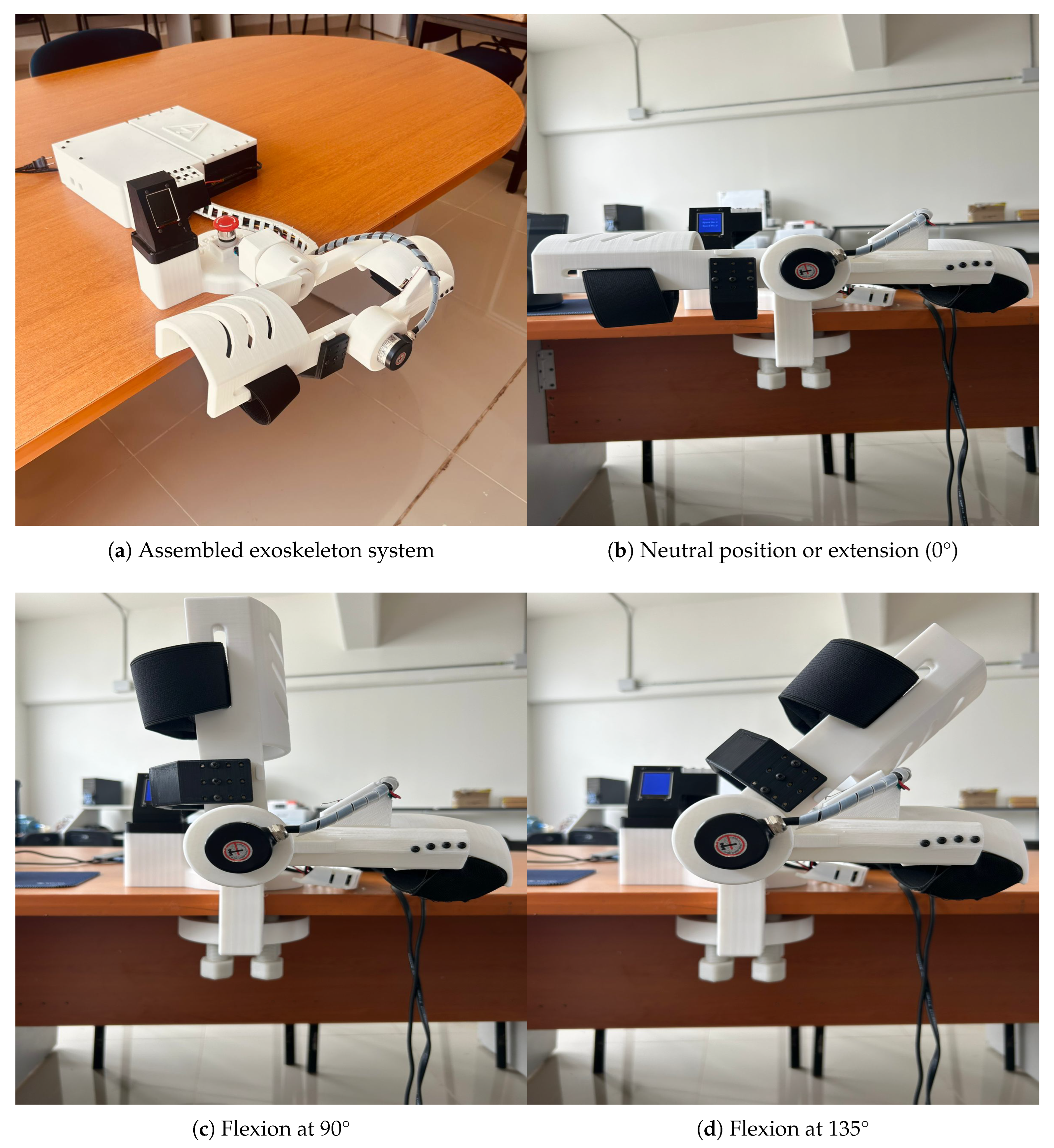
Figure 9 depicts the final version of the fully assembled prototype of the exoskeleton body structure and the range of motion used for the rehabilitation-based experiments.
3.2. Automatic Control
PD Controller with Gravity Compensation Simulation
Simulation A Proportional-Derivative (PD) controller with gravitational compensation was implemented in
Matlab to simulate and control the motion of a single-joint robotic exoskeleton designed for elbow rehabilitation. The system is modeled as a single degree-of-freedom (DOF) planar manipulator, representing the upper limb segment, with anthropometric parameters approximating the human arm. The dynamic model includes the mass of the forearm (
), its center of mass (
), and viscous friction (
), while ignoring other parameters that do not affect the results. The simulation uses a sampling time of
over a total simulation duration of
. The gravitational torque is calculated as:
Moreover, the PD control law incorporates this term to compensate for gravitational effects, enhancing trajectory tracking accuracy. The reference trajectory for the joint is defined as a 45° amplitude oscillation governed by a cosine function, and its derivative is used as the desired angular velocity. The control torque
T applied at each time step is computed using:
where
and
. The controller gains,
and
, were determined through a simulation-based tuning process in
Matlab using the dynamic model described earlier. The objective was to achieve a responsive yet stable motion, minimizing overshoot and steady-state error while keeping the movement smooth for rehabilitation purposes. Different gain combinations were tested in the simulation, assessing how the system responded to both step commands and trajectory-tracking tasks under gravitational load compensation. After evaluating these scenarios, the selected values of
and
offered the best balance between tracking accuracy and control effort. The system dynamics are updated using Euler integration, incorporating the inertia matrix
M, Coriolis terms (neglected in this simplified model), and viscous friction. The inertia matrix is defined as
. A real-time visualization is generated to display the evolution of the joint position and the forearm movement, its reference, and the applied torque.
The simulation results, as shown in
Figure 10, illustrate the position tracking performance over time. The reference trajectory, shown in green, follows a sinusoidal pattern, while the joint, represented by a red link with a blue circle at the end effector, tracks the reference using a PD controller with gravitational compensation. A slight tracking error can be observed, particularly during direction changes, where a small overshoot occurs before smoothly converging to the desired trajectory. Afterwars, the general results of the simulation are described in
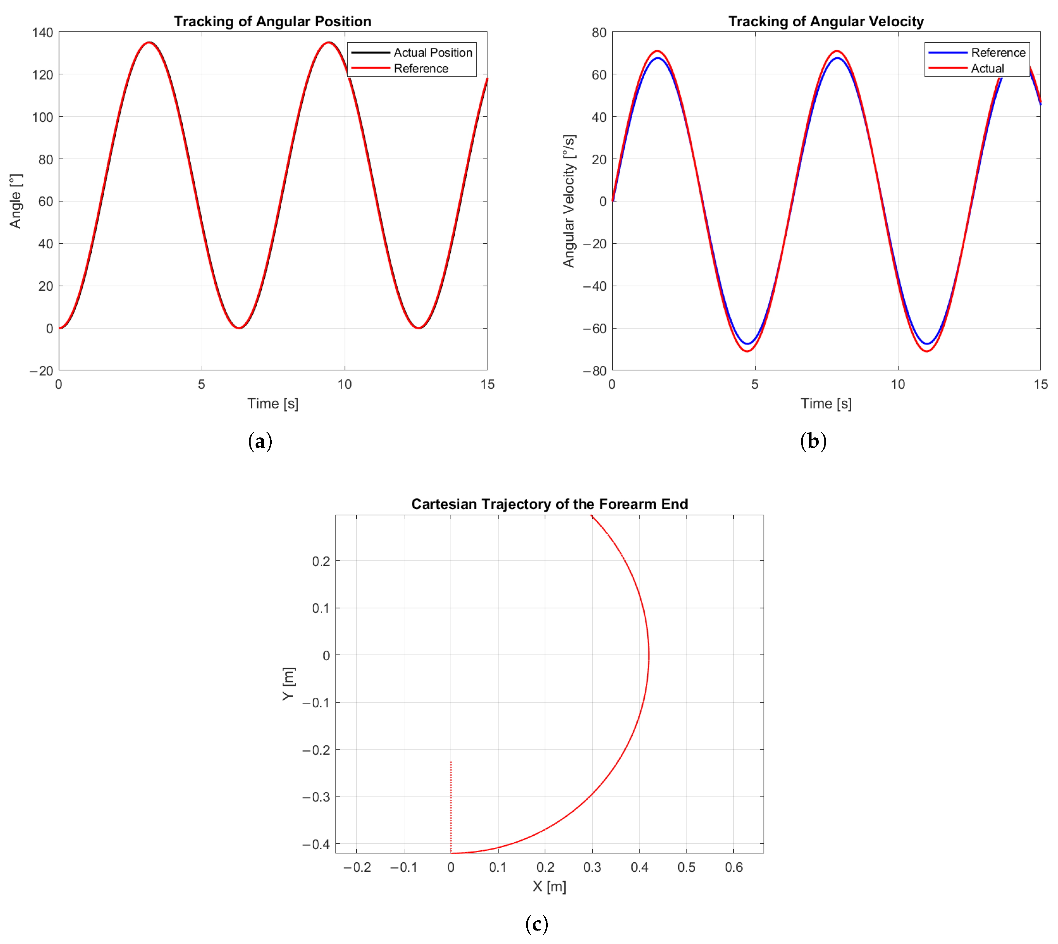
Figure 11.
The accuracy of the system was assessed considering two performance variables: the joint position, illustrated in
Figure 11a, where the input signal is represented in red and the manipulated variable in black, and the angular velocity, shown in
Figure 11b, where the input signal is represented in blue and the manipulated variable in red. The mean position error was calculated according to:
Similarly, for the average angular velocity error:
The obtained results indicate that the system achieved an average position error of 2.35% (1.24°) and an average angular velocity error of 3.12% (0.85°/s). These values demonstrate a high level of accuracy in both static and dynamic joint control. Finally, the Cartesian trajectory is shown in
Figure 11c, illustrating how the joint moved over time in the Cartesian plane, covering approximately 135° as intended by the system design.
PD controllers have evolved significantly over recent years, and several related works have demonstrated their capability to efficiently control systems similar to the one addressed in this study. For instance, Hu et al. [
42] developed an adaptive PD controller capable of accurately tracking human gait trajectories obtained through a motion capture system, achieving faster convergence to the desired path while mitigating excessive initial output torque. Compared to such adaptive approaches, the PD controller implemented in this work, although non-adaptive, exhibits comparable tracking accuracy within the tested operational range. While Hu et al. [
42] optimized their design for dynamic human gait scenarios with variable parameters, our results demonstrate that even a fixed-gain PD configuration can achieve high-fidelity tracking in real-time applications, with error magnitudes well within acceptable limits for precise angular position control. However, there are also other techniques capable of achieving comparable results. For example, Herbin et al. [
43] presented the design and implementation of a PID controller with friction compensation to counteract the nonlinear effects produced by Bowden cables in their 7-DOF upper-limb exoskeleton, Exoarm. Their approach proved to be highly robust, particularly in delivering precise and repetitive sinusoidal trajectories for the elbow joint during bilateral teleoperation tasks. Nevertheless, the Exoarm system was designed for laboratory use and, due to its size and complexity, was not intended for portable or home-based applications.
The results obtained in the real-time implementation of the exoskeleton system were consistent with the simulated dynamics as presented in
Figure 12. The PD controller was embedded into the microcontroller to regulate the angular position of the elbow joint, enabling controlled flexion–extension movements of the forearm.
The microcontroller internally generated a sinusoidal reference signal that served as the setpoint for angular position control. This reference waveform was modulated by feedback from two mechanical limit switches positioned at the motion extremes, approximately 135° for maximum flexion and 0° for full extension. To safeguard both the device and the user, additional buffer zones were incorporated at each limit, preventing excessive movement and ensuring mechanical safety throughout operation.
In this case, the position error was evaluated using three standard metrics: the Mean Absolute Error (MAE), which represents the average of the absolute differences between the reference angular position and the actual angular position ; the Root Mean Square Error (RMSE), which measures the square root of the mean of the squared differences, thus penalizing larger deviations; and the maximum absolute error , which indicates the largest instantaneous deviation observed.
Mathematically, these are expressed as:
where
.
From the experimental data in
Figure 12, the results were obtained as follows:
,
, and
, with the largest deviations occurring near the extrema of the trajectory, which is consistent with the response of the PD controller.
3.3. GUI-BCI Integration
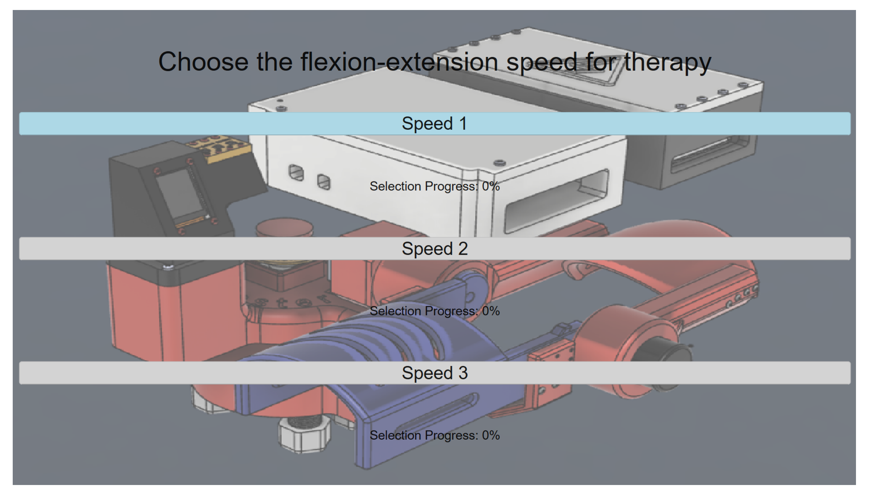
Live interaction between the BCI and the GUI results in a hands-free, neurophysiology-led interaction model tailored for rehabilitation environments, leading to considerably enhanced accessibility and user-driven control. Besides the EEG signal recognition on a GUI, the device also provides a manual control capability using a custom embedded interface with hardware buttons and a TFT screen inside the GUI. This dual operation mode capability is essential in the testing environment in clinical settings where tests can be performed either autonomously or supervised. The processing stages are monitored continuously through the interface, as shown in
Figure 13, where intuitive user interaction is provided.
Starting from
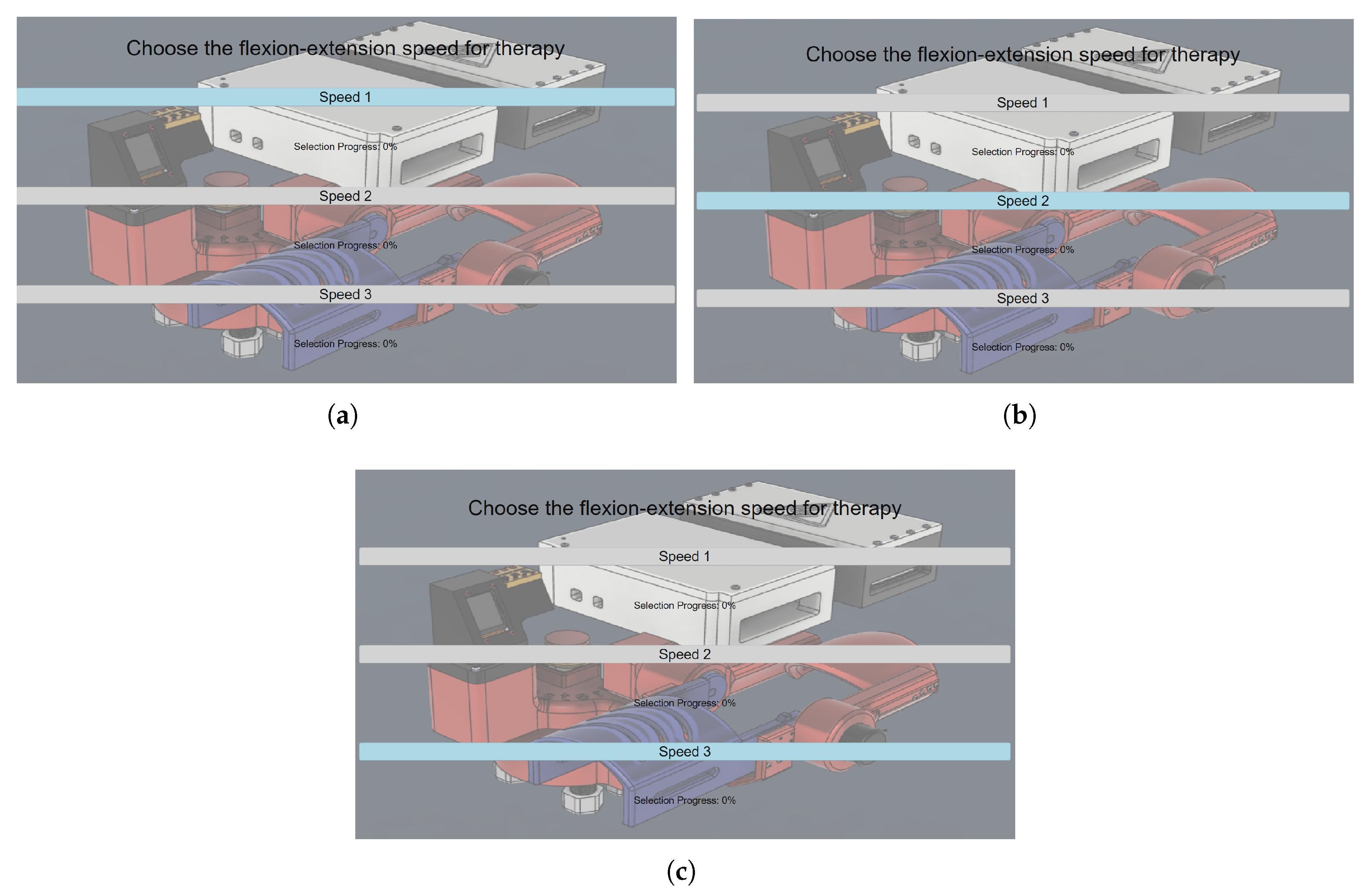
Section 2.7 of the pipeline, the choice is activated once the user voluntarily blinks. Each blink triggers an iteration over the available speed options in a top-to-bottom sequence, as illustrated in
Figure 14. Once the last option is reached, the iteration direction reverses, and subsequent blinks move the selection from bottom to top.
When prompted to confirm a therapy speed, either by instruction or personal choice, the individual focuses on the desired option and closes their eyes. The onset of sustained alpha wave activity (in the 8–13 Hz band) is then detected, corresponding to the individualized threshold established during the training phase.
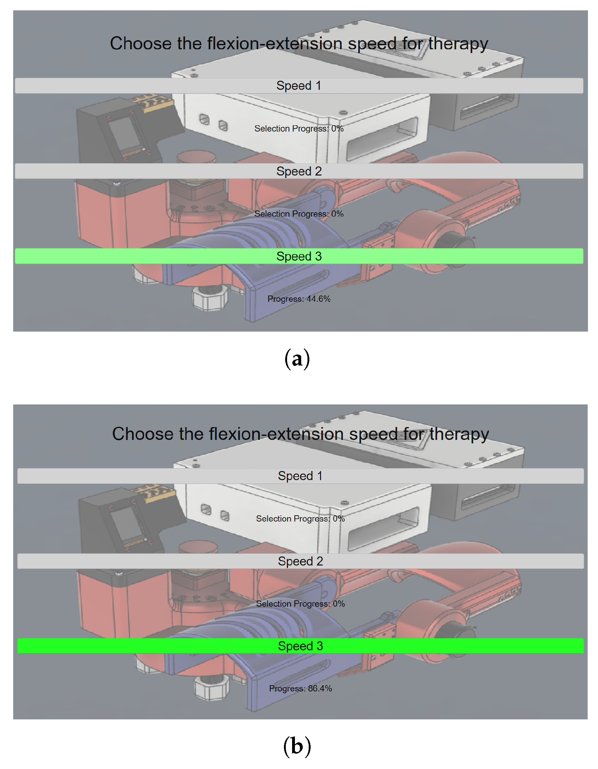
To provide visual feedback and encourage continued eye closure, a conversion is applied to represent the detected alpha power as a percentage-based progress bar. The user is required to maintain relaxation (reflected by alpha activity) until the progress bar reaches 100%, as shown in
Figure 15 where the increase of the alpha activity is clearly visible as the green color starts appearing with a soft transparency at 44.6% in
Figure 15a, until it reaches a higher level at 86.4% and the intensity of the color green increases at the same rate as observed in
Figure 15b. Once this threshold is met, the GUI transmits the corresponding command to the control unit, initiating the therapy session at the selected speed. The exoskeleton then performs continuous flexion–extension movements for a total duration of 30 s.
3.4. EEG Data Acquisition
Electroencephalogram (EEG) signals were recorded for five healthy human subjects during training and testing of the BCI system. The purpose of this step was to perform system calibration by determining personal thresholds for detection of active alpha wavebands and voluntary eye blinks.
To attain this, a comprehensive training protocol was customized for each subject to achieve reliable alpha rhythm and blink-related signals. The alpha band training was structured around an eyes-open/eyes-closed alternation paradigm in order to induce a recordable level of change in alpha activity, whereas the eye-blink training comprised specific intervals of controlled blinking and relaxed intervals.
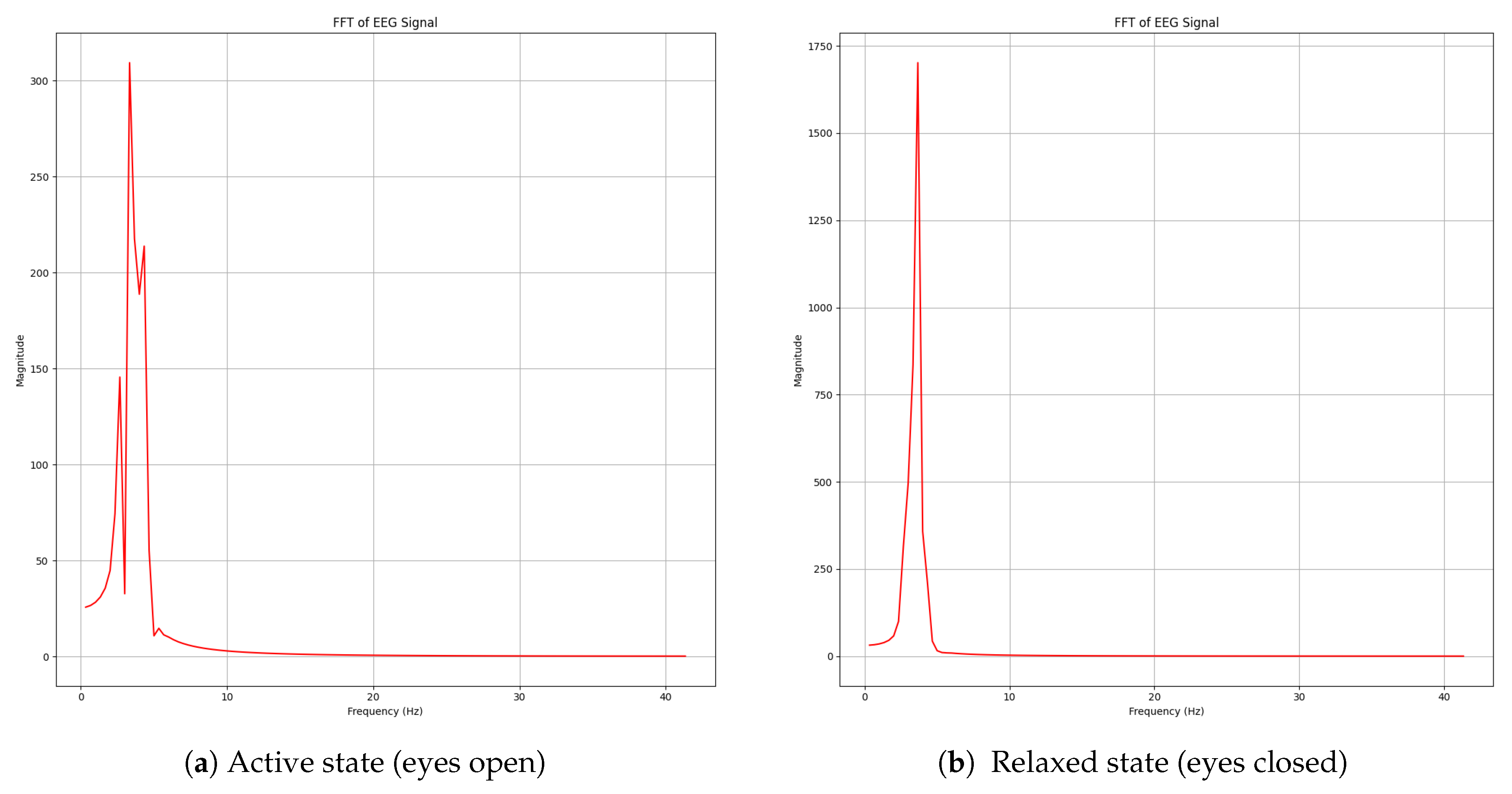
As illustrated in
Figure 16, the signal processing pipeline successfully extracted relevant features from the EEG signals using the previously described mathematical methods. Once the EEG signal had been segmented, the system performed online estimates of its frequency domain to identify the increase of alpha dominance and eye movement contamination. This analysis was performed by integrating the area under the curve of the signal’s FFT, taking into account the spectral power in each frequency band of interest.
Responses were labeled by comparing the absolute value of these values with individual participant-dependent thresholds extracted in the calibration phase in order to normalize responses for each participant. Above this threshold, a clear enhancement of spectral amplitude was detected in all the frequency bands, especially in the alpha wave (8–13 Hz) regime, which had already been reported during eye closing. Additionally, transient increases in the 4–20 Hz range were identified, which are attributed to eye-blink artifacts. These findings confirm that the system is capable of discriminating between neurophysiological patterns and ocular artifacts through real-time spectral analysis.
The spectral peak observed in
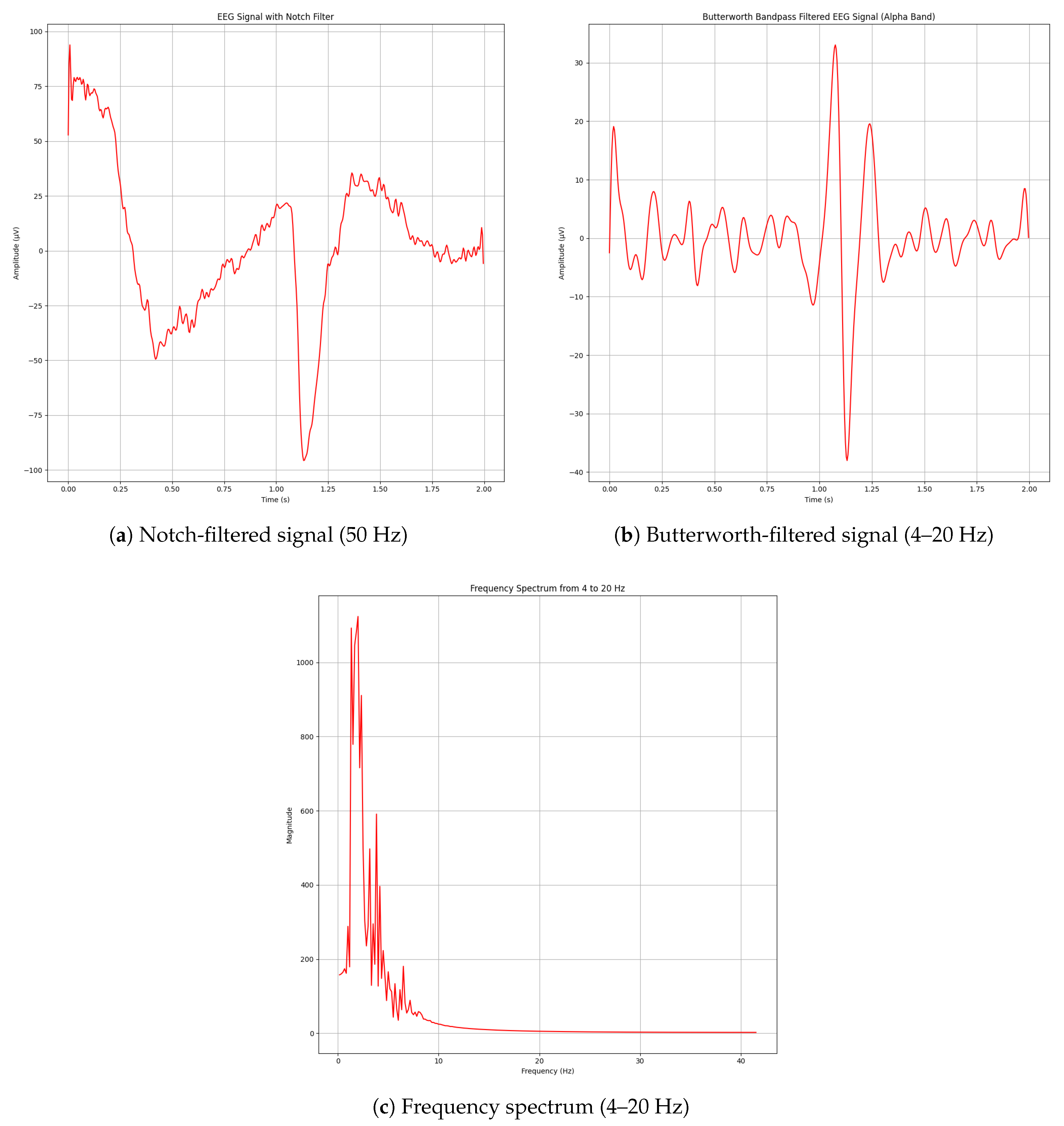
Figure 16b identifies when alpha waveband activity emerges in real time as the subject closes their eyes. Additionally, eye-blink artifacts were detected through the same frequency-based approach (excluding wavelet denoising). As eye-blinks produce a prominent and easily distinguishable disturbance in the time domain, their successful acquisition is demonstrated in
Figure 17.
A total of five healthy adult participants (mean age: 21.6 ± 1.34 years; 4 male, 1 female) took part in the study. All participants had no history of neurological or psychiatric disorders, normal or corrected-to-normal vision, and no prior experience with EEG-based interfaces. A brief neurological examination was conducted prior to data collection, including assessment of cranial nerve function, motor strength, coordination, and sensory function, confirming the absence of any deficits. This ensured that all measured signals were representative of typical cortical activity without pathological alterations.
Table 3 summarizes the alpha wave detection accuracy for each participant during both eyes-closed and eyes-opened phases. The results indicate consistently high detection accuracy across participants, with an overall mean accuracy of 86.25%, suggesting that the system reliably distinguishes alpha-band activation under different visual conditions.
The participants completed a testing protocol following an initial calibration/training phase to evaluate the system’s EEG alpha-band detection accuracy. The procedure consisted of the following steps:
Initial preparation period (no action).
Eyes closed for 8 s (relaxation phase).
Eyes opened for 9 s (active phase).
Alternating cycles of closed/open eyes repeated four times.
The accuracy of alpha wave detection was evaluated by comparing the system’s binary classification outputs against the known ground truth based on the eye condition (closed = increase of alpha activity, open = decrease).
Table 3 presents the detection results for each session and subject.
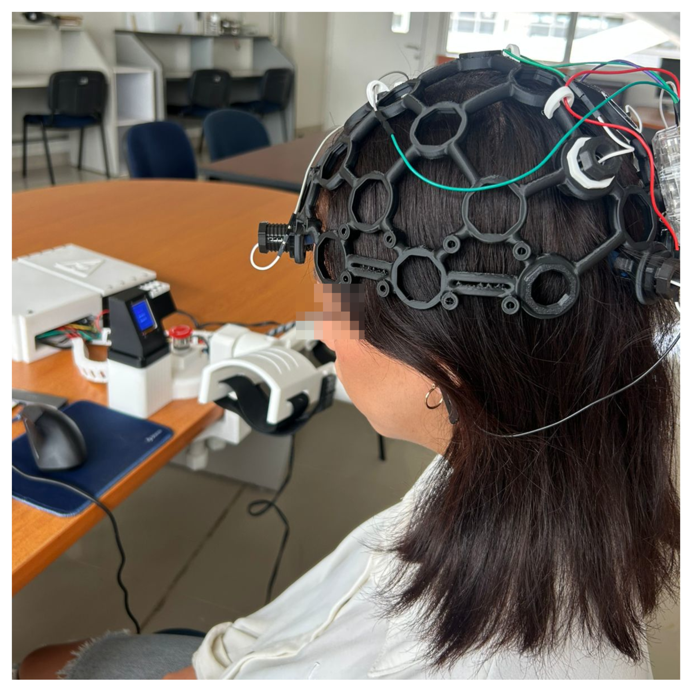
Figure 18 shows subjects’ participation for the accuracy tests using the EEG equipment. The results in
Table 3 show that alpha wave detection achieved high accuracy across the five participants, with an overall mean accuracy of 86.25%. In all subjects except Participant 5, accuracies in both eyes-opened and eyes-closed phases exceeded 82%, with several cases surpassing 97% in the eyes-opened condition. The eyes-opened phase consistently yielded higher accuracies compared to eyes-closed, suggesting that the classifier effectively distinguishes alpha-band activity even when ocular artifacts are more likely to occur. Participant 4 and Participant 5 showed slightly lower mean accuracies (82.77% and 80.35%, respectively), which may reflect individual variability in alpha rhythm amplitude or EEG signal quality. Nevertheless, the consistently high detection rates across conditions and participants indicate that the proposed method is robust for identifying alpha activity under different visual states. As observed in
Table 3, each session alternates between 8 s of eyes closed (EC) and 9 s of eyes open (EO). Accuracy is computed as the proportion of correctly detected states (increase/decrease of alpha waves) relative to the total number of windows per condition.
3.5. System Operation for Medical Rehabilitation
One healthy adult with no documented neurological disorders or motor dysfunction participated in the operation tests to evaluate the system in a rehabilitation context. The participant was briefed with detailed instructions on how to behave during the training phase and while performing flexion-extension movements with the exoskeleton worn.
Initially, a session was conducted to establish the thresholds for alpha band activity and eye-blink detection. For the alpha wavebands calibration and eye-blink threshold, the same training described in
Section 2.6 was followed.
As the EEG signal is stochastic, the relaxations should be consistent during the training phase and operational phase. Accordingly, the training session was performed in the physical place of the exoskeleton. The subject was to keep calm and to remain relaxed as as possible.
Three operational tests were carried out with the same subject following the structure described below:
These tests validated the synchronization between EEG signal detection, user interface navigation, and exoskeleton actuation under real-time conditions.
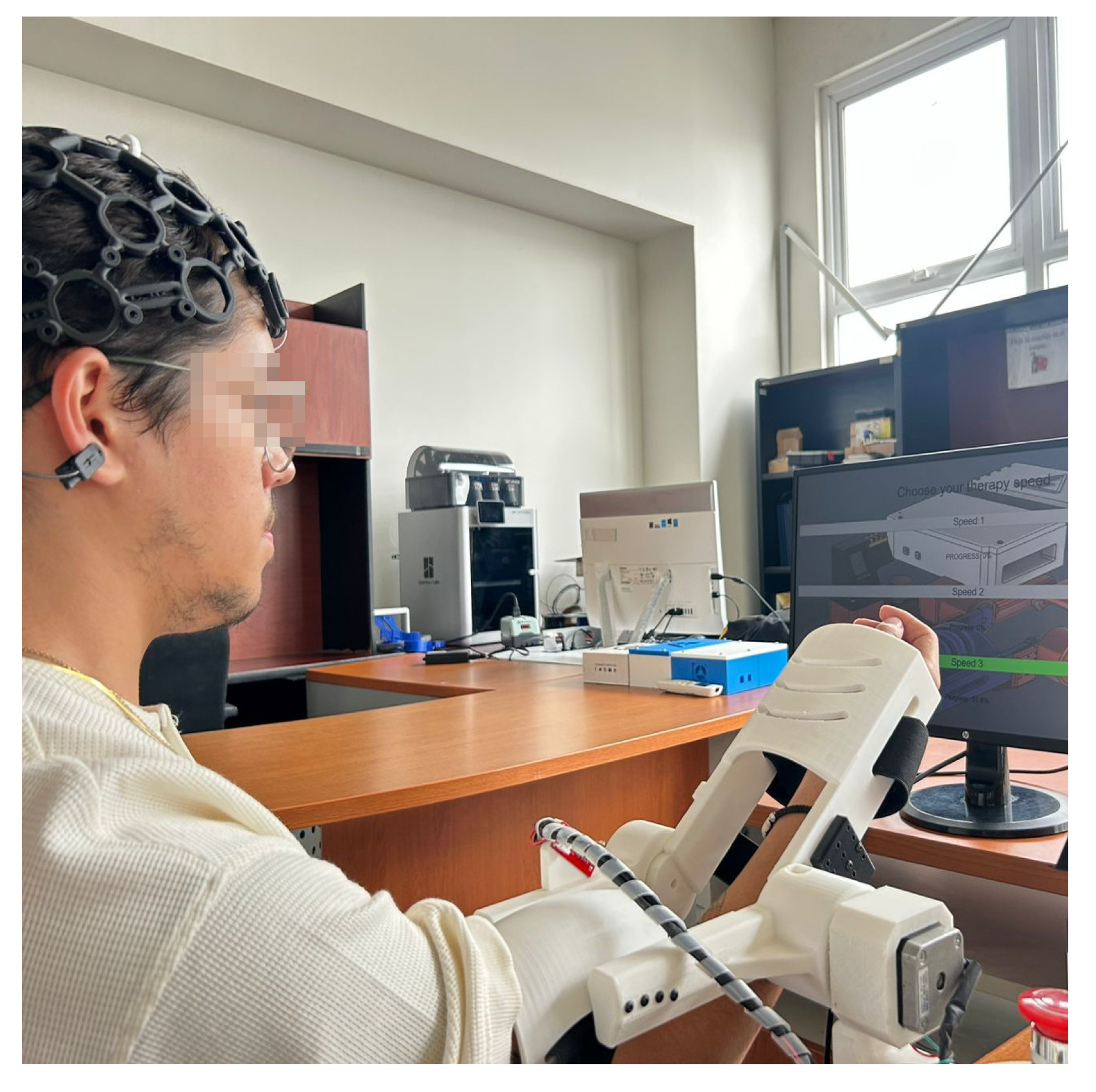
As shown in
Figure 19a, the subject begins the relaxation phase by closing their eyes, thereby initiating the generation of alpha band activity. This activity is used by the system to start filling the progress bar. The eye-blink detection functionality was also tested during this phase and performed satisfactorily.
Once the progress bar was fully completed, the GUI automatically triggered the control signal to activate the exoskeleton. As illustrated in
Figure 19b, the system executed the flexion-extension therapy at the selected speed for a duration of 30 s. At the end of the therapy, the exoskeleton returned to the starting position, and the GUI redirected the user to the main menu for a new speed choice.
4. Discussion
Use of EEG in neurorehabilitation has grown exponentially over the last decade, as indicated by a literature search by Tsiamalou et al. [
44]. The introduction and verification of a real-time EEG-based control method of an upper-limb exoskeleton has a great impact on the process of bringing non-invasive brain-computer interfaces (BCIs) into the context of rehabilitative devices. This work shows that spectral analysis methods, particularly in the alpha frequency band (8–13 Hz) and in detecting eye-blink artifacts (4–20 Hz), can be effectively applied for decoding neural user state for triggering and influencing robotic exoskeletons for therapy.
Table 3 summarizes the alpha wave detection accuracy for each participant during both eyes-closed and eyes-opened phases. The results indicate consistently high detection accuracy across participants, with an overall mean accuracy of 86.25%, suggesting that the system reliably distinguishes alpha-band activation under different visual conditions. The signal processing pipeline used in this work was found to be robust and efficient. Analysis of the multi-stage filtering, including baseline correction with a notch filter from 0.5 to 50 Hz, artifact rejection through wavelet-based denoising, and frequency-selective enhancement with a Butterworth bandpass filter, demonstrated the system’s ability to separate neurophysiological patterns of interest. The frequency-domain analysis via Fast Fourier Transform (FFT) enabled unambiguous identification of alpha rhythm increases associated with relaxed states, and transient spikes attributable to eye blinks. Such spectral components were visually and quantitatively confirmed, which can be seen from the accuracy results that appear in
Table 3, where we can observe that the signal processing pipeline implemented in the system was suitable to detect the characteristic alpha waveband activity in a number of subjects. The mean accuracy was 86.25%, and the mean individual accuracy ranged from 80.35% to 89.78%, pointing to robust generalization of the threshold-based alpha detection method.
A clear trend was discovered between all subjects that showed better detection with Eyes Opened rather than Eyes Closed. This is in line with the expected physiological tendency of alpha waves to be suppressed when eyes are open, and thus easier to identify and classify when they are not present. In contrast, in the eyes-closed resting state, the alpha activity increases but sometimes fluctuates because of idiosyncratic brain rhythms as well as muscle artifacts (which reduce the classification performance).
Subject 2 obtained the highest mean detection rate (89.78%) indicating a more observable percentile between alpha wave activation and deactivation stages.
On the other hand, Subject 5 achieved the lowest mean accuracy (80.35%), and the reason might be the lower quality of their EEG signal or a weaker alpha pattern in the eyes-closed state.
These findings further confirm the reliability of the introduced Butterworth filtering (8–13 Hz), FFT-based power extraction, and statistical thresholding methods. They also underscore the need for personalized calibration, given that performance can differ among users due to neurophysiological variance. In future work, it may be beneficial to introduce adaptive thresholding strategies or data-driven classifiers to enhance the reliability of classification, particularly during eyes-closed testing, which was more variable. The progress bar interface powered by alpha wave activity provides an intuitive way for users to begin commands without using physical buttons or other external tools. Eye-blink recognition is integrated to improve system adaptability to control menu selection and UI interaction. This dual-control strategy (alpha band detection + blink recognition) allows for hands-free and motor-independent operation, an essential feature for patients with motor impairments. The relevance of this system extends beyond its technical success. From a clinical point of view, the non-invasive assessment of the intention and the consequent ability to adjust the rehabilitation path accordingly is a novel road for the patient’s involvement in neurorehabilitation.
Moreover, involving the patient’s thinking in the control of the system makes it an interactive process that could work better. This could result in increased neuroplasticity and recovery, particularly in patients with stroke, traumatic brain injuries, and motor neuron disease [
44].
Furthermore, the low-cost architecture relative to the transparent commercial EEG device and open-source GUI of the system also achieves clinic and home device expansion and popularization. Unlike many other robotic therapy machines, which typically require a human pilot and fuel for calibration, this one is intended to be straightforward and to run in near real-time, making the learning curve for patients and their healers somewhat less daunting.
There are several limitations that should be acknowledged despite the promising results. EEG signals are intrinsically noisy and are especially independent of the lab environment. Although wavelet-based denoising and frequency filtering mitigate these effects, future work should explore adaptive thresholding and machine learning-based classification to enhance performance. In order to extend this study for future work, control strategies for the angular position could be potentially improved by adapting an intelligent non-linear PID controller providing a more robust, efficient and perturbance proof system allowing the patient a more confident security in the operation of the device. Additionally, broader clinical trials with diverse patient populations will be necessary to validate the system’s efficacy in rehabilitative protocols.
5. Conclusions
The most significant contribution of this work is the design of a novel EEG-based Graphical User Interface (GUI) to enhance user engagement and self-regulation, while lowering emotional barriers such as anxiety and stress that can hinder rehabilitation. By combining alpha-band activation in relaxed states with the system’s ability to discriminate ocular artifacts from neurophysiological patterns, it demonstrates the potential to non-invasively detect user intent. These elements are crucial for developing rehabilitation interventions that are patient-centered and adaptable to individual needs.
Although the current design validates the basic functioning of the system under controlled conditions, further work is required to address several limitations. Clinically, we have not yet tested the system on patient populations such as post-stroke, traumatic brain injury, or age-related neurodegeneration, and specific adaptations will be required to accommodate different cognitive and motor capabilities. Technically, robustness against noise and variability across recording sessions must be improved, and algorithms should be optimized for real-time performance in less-controlled environments. From a scalability perspective, hardware portability, communication reliability, and integration into diverse clinical workflows remain challenges. Balancing the technical complexity of multimodal signal processing (EEG, EDA, HRV) with its tangible clinical benefits will also be an important consideration for future development.
This work provides groundwork for the progression of EEG-based exoskeletons from laboratory prototypes to certified therapeutic devices, both in clinics and home health care. The system is conceived as a rehabilitation device and as a potential stimulator for neurorehabilitation through the repetition of goal-directed motor tasks driven by the user’s neural motor acts. Integration of brain signal analysis with adaptive robotics represents an important frontier in neuroengineering and digital health. The reproducible, user-centric approach presented here specifies explicit goals for technological performance and patient perception, which may disrupt standard rehabilitation models by offering low-cost, personalized therapy. In real therapy settings, the platform could be deployed with adjustable training protocols, supervised by clinicians, and integrated into task-specific rehabilitation programs.
In the future, the following work will be conducted to increase the clinical and technical maturity of the proposed EEG-driven exoskeleton:
Multidisciplinary Clinical Trials: Conduct longitudinal studies in collaboration with neurologists, physical therapists, psychologists, and psychiatrists to (i) refine inclusion and exclusion criteria, (ii) tailor training protocols to specific patientphenotypes (such as post-stroke hemiparesis, traumatic brain injury, and age-related motor decline), and (iii) evaluate functional gains with standardized outcome scales such as the Fugl–Meyer Assessment [
45,
46,
47] and the Modified Ashworth Scale [
48].
Motor-Imagery Integration: Beyond eye-blink selection and alpha-band relaxation cues, motor imagery (MI) tasks—particularly kinesthetic MI of wrist extension and flexion—will be incorporated to (i) provide a more direct neural signal, (ii) enhance user engagement, and (iii) promote Hebbian-like plasticity through coupling of imagined and executed actions.
Adaptive and Explainable Signal Processing: Implement adaptive thresholding and machine-learning classifiers to enhance robustness across sessions and users, while incorporating explainable AI tools to improve interpretability and clinical trust.
Psychophysiological Monitoring: Record electrodermal activity (EDA), heart-rate variability (HRV), and subjective stress questionnaires alongside EEG to better understand the user’s emotional state. This information can be integrated to adjust task difficulty in real time, avoiding mental fatigue and sustaining motivation.
Home-Based Deployment: Develop a low-cost, open-source tele-rehabilitation platform with secure data streaming for remote monitoring by clinicians, and explore edge-computing approaches to ensure privacy and real-time performance.
Together, these aims will deepen the understanding of the neurophysiology of recovery, improve the efficacy and flexibility of brain–machine control, and rigorously assess the real-world therapeutic impact of the system in neurorehabilitation.
6. Patents
The industrial design titled “Modelo industrial de exoesqueleto para rehabilitación de codo” has been registered under the identification number MX/2024/91417, with registration number 71111 issued by the Mexican Institute of Industrial Property (IMPI).
Author Contributions
A.F.P.-V., F.D.J.S.-V., J.A.B.-M., J.C.R.-C. and J.-A.C. were responsible for the conceptualization of the project, the processing of EEG signals, the methodological development, and the overall supervision of the research. J.Y.R.-M. and G.O.-T. contributed to the generation and classification of critical values through statistical processing and data cleansing, as well as to the analysis and interpretation of the results. C.A.C.-M. led the design and development of the exoskeleton, the electronic circuit, the software for EEG signal processing, and the graphical user interface for the rehabilitation therapy. C.E.H.-M. and M.D.F.-J. were responsible for evaluating the project’s societal impact and ensuring compliance with ethical, psychological, and legal considerations. All authors have read and agreed to the published version of the manuscript.
Funding
This research received external funding for project development, with support from Universidad de Guadalajara (UDG).
Institutional Review Board Statement
This study protocol was approved by the Ethics Committee of El Comité de Ética en Investigación Científica del Centro Universitario de los Valles under protocol code CEI/52/2024.
Informed Consent Statement
Informed consent was obtained from all study participants.
Data Availability Statement
The original contributions presented in this study are included in the article. Further inquiries can be directed to the corresponding author.
Conflicts of Interest
The authors declare no conflict of interest.
Abbreviations
The following abbreviations are used in this manuscript:
| List of Acronyms | |
| Acronym | Meaning |
| EEG | Electroencephalography/Electroencephalographic |
| BCI | Brain–Computer Interface |
| PCB | Printed Circuit Board |
| PPR | Pulses Per Revolution |
| PD | Proportional–Derivative |
| CAD | Computer-Aided Design |
| DoF | Degree(s) of Freedom |
| GUI | Graphical User Interface |
| Hz | Hertz |
| ISO | International Organization for Standardization |
| IEC | International Electrotechnical Commission |
| CVA | Cerebrovascular Accident |
| EMG | Electromyography/Electromyographic |
| EMI | Electromagnetic Interference |
| DWT | Discrete Wavelet Transsform |
| FFT | Fast Fourier Transform |
| DFT | Discrete Fourier Transform |
| IDWT | Inverse Discrete Wavelet Transform |
| MWT | Mother Wavelet Transform |
| UDG | Universidad de Guadalajara |
| FFF | Fused Filament Fabrication |
| PLA | Polylactic Acid |
| PETG | Polyethylene Terephtalate Glycol |
| PLI | Power Line Interference |
| PSD | Power Spectral Density |
| AUC | Area Under the Curve |
| ADE | Electrodermal Activity |
| MI | Motor Imagery |
| HRV | Heart-rate Variability |
References
- Ceravolo, M.G.; Christodoulou, N. Physical and Rehabilitation Medicine for Medical Students; Edi Ermes: Milan, Italy, 2019. [Google Scholar]
- Anthony, S.R.; Babu, P.; Paplikar, A. Aphasia severity and factors predicting language recovery in the chronic stage of stroke. Int. J. Lang. Commun. Disord. 2025, 60, e70030. [Google Scholar] [CrossRef] [PubMed]
- Pérez Vidal, A.F.; Rumbo Morales, J.Y.; Ortiz Torres, G.; Sorcia Vázquez, F.d.J.; Cruz Rojas, A.; Brizuela Mendoza, J.A.; Rodríguez Cerda, J.C. Soft exoskeletons: Development, requirements, and challenges of the last decade. Actuators 2021, 10, 166. [Google Scholar] [CrossRef]
- Duanmu, D.; Li, X.; Huang, W.; Hu, Y. Soft Finger Rehabilitation Exoskeleton of Biomimetic Dragonfly Abdominal Ventral Muscles: Center Tendon Pneumatic Bellows Actuator. Biomimetics 2023, 8, 614. [Google Scholar] [CrossRef]
- Tian, M.; Liu, Y.; Chen, Z.; Wang, X.; Zhang, Q.; Liu, B. Biomimetic design and validation of an adaptive cable-driven elbow exoskeleton inspired by the shrimp shell. Biomimetics 2025, 10, 271. [Google Scholar] [CrossRef] [PubMed]
- Chen, Z.; Wu, J.; Ju, C.; Wang, X.; Tian, M.; Liu, B. Design and Control of a Cable-Driven Exoskeleton System for Upper-Extremity Rehabilitation. IEEE Access 2024, 12, 187964–187975. [Google Scholar] [CrossRef]
- Sarhan, S.M.; Al-Faiz, M.Z.; Takhakh, A.M. EEG-Based Control of a 3D-Printed Upper Limb Exoskeleton for Stroke Rehabilitation. Int. J. Online Biomed. Eng. 2024, 20, 99–112. [Google Scholar] [CrossRef]
- En, L.J.; Ng, N.C.-S.; Wong, R.S.-Y. Exoskeletons in Neurological Rehabilitation: A Commentary on Current Evidence and Future Directions. Quantum J. Med. Health Sci. 2025, 4, 129–137. [Google Scholar] [CrossRef]
- Nasr, A.; Inkol, K.; McPhee, J. Safety in Wearable Robotic Exoskeletons: Design, Control, and Testing Guidelines. J. Mech. Robot. 2025, 17, 050801. [Google Scholar] [CrossRef]
- Luecha, T.; Yeoh, W.L.; Yang, Y.; Choi, J.; Loh, P.Y.; Muraki, S. Exploring Grip, Voice, and Electromyography Signals to Initiate Elbow Flexion with a Wearable Robot Arm. J. Robot. 2025, 2025, 4988295. [Google Scholar] [CrossRef]
- Shankar, R.; Goh, Z.; Qian, X. Perceptions, Attitudes, and Lived Experiences of Therapists with Lower Limb Robotic Exoskeletons in Stroke Rehabilitation: A Protocol for a Systematic Review of Qualitative Studies. medRxiv 2025. [Google Scholar] [CrossRef]
- Al-Quraishi, M.S.; Elamvazuthi, I.; Daud, S.A.; Parasuraman, S.; Borboni, A. EEG-Based Control for Upper and Lower Limb Exoskeletons and Prostheses: A Systematic Review. Sensors 2018, 18, 3342. [Google Scholar] [CrossRef]
- Chiu, K.I.A.; Taylor, C.; Saha, P.; Geddes, J.; Bishop, T.; Bernard, J.; Lui, D. Actively Controlled Exoskeletons Show Improved Function and Neuroplasticity Compared to Passive Control: A Systematic Review. Glob. Spine J. 2025, 21925682251343529. [Google Scholar] [CrossRef]
- Bülent Fidan, C.; Husrev Akdeniz, A. Eeg-Based Brain-Computer Interface Systems for Exoskeleton Control: A Review with Conceptual Insights. (n.d.). Available online: https://www.researchgate.net/publication/393946286 (accessed on 10 August 2025).
- Hernandez-Navarro, A.J.; Ortiz-Torres, G.; Pérez-Vidal, A.F.; Cervantes, J.A.; Sorcia-Vázquez, F.D.J.; López, S.; Ramos-Martinez, M.; Lozoya-Ponce, R.E.; Jauregui, N.F.D.; Rumbo-Morales, J.Y.; et al. Design, Manufacturing, and Electroencephalography of the Chameleon-1 Helmet: Technological Innovation Applied for Diverse Neurological Therapies. Applied System Innovation 2025, 8, 56. [Google Scholar] [CrossRef]
- Tae-Yeun, K.; Sung-Hwan, K. Design and implementation of BCI-based intelligent upper limb rehabilitation robot system. ACM Trans. Internet Technol. 2021, 21, 1–17. [Google Scholar] [CrossRef]
- Vidal, A.F.P.; Cervantes, J.-A.; Rumbo-Morales, J.Y.; Sorcia-Vázquez, F.D.J.; Ortiz-Torres, G.; Moncada, C.A.C.; Arias, I.d.l.T. Development of RelaxQuest: A serious EEG-controlled game designed to promote relaxation and self-regulation with a potential focus on ADHD intervention. Appl. Sci. 2024, 14, 11173. [Google Scholar] [CrossRef]
- Ranawaka, U.K. Bites and Stings: Exotic Causes of Stroke in Asia. Cerebrovasc. Dis. Extra 2024, 14, 141–147. [Google Scholar] [CrossRef] [PubMed]
- Ugwu, V.I.; Casmir Uzoefuna, C. Clinico Demographic Patterns of Childhood Cerebrovascular Accident in Enugu State Teaching Hospital. Newport Int. J. Sci. Exp. Sci. 2025, 6, 27–30. [Google Scholar] [CrossRef]
- Ezeuko Lilian, C.; Odunvbun Magdalene, E.; Ikejiaku Udochikwuka, P.; Ike Innocent, I. Cerebral Artery Blood Flow Velocities in Children with Sickle Cell Anaemia at the Federal Teaching Hospital, Owerri. Niger. J. Paediatr. 2024, 51, 348–355. [Google Scholar] [CrossRef]
- Guo, Y.; Wang, J.; Gao, M.; Sun, H.; Cheng, W. The therapeutic effect of scraping on hemiplegia patients after stroke: A meta-analysis. Medicine 2025, 104, e42743. [Google Scholar] [CrossRef]
- Meena, C.P.; Pandey, V.; Panda, S.; Gangadevi, P.; Rana, N. Level of Functional Independence in Post-stroke Patients: A Descriptive Study. J. Med. Evid. 2025. [Google Scholar] [CrossRef]
- Wang, J. An exoskeleton upper limb rehabilitation robot based on electroencephalography. MCB Mol. Cell. Biomech. 2024, 21, 77. [Google Scholar] [CrossRef]
- Abery, P.; Canetti, E.F.D.; Hing, W. The role of lower limb exoskeletons in rehabilitation: A scoping review. Phys. Ther. Rev. 2025, 30, 118–136. [Google Scholar] [CrossRef]
- ISO 13485:2016; Medical Devices—Quality Management Systems—Requirements for Regulatory Purposes. International Organization for Standardization: Geneva, Switzerland, 2016.
- IEC 60601-1:2005+AMD1:2012+AMD2:2020; Medical Electrical Equipment—Part 1: General Requirements for Basic Safety and Essential Performance. International Electrotechnical Commission: Geneva, Switzerland, 2020.
- Wei, Y.; He, H. Research on the motion characteristic of elbow joint angle based on the sEMG of single muscle. Cogent Eng. 2016, 3, 1247613. [Google Scholar] [CrossRef]
- Holzbaur, K.R.S.; Murray, W.M.; Gold, G.E.; Delp, S.L. Upper limb muscle volumes in adult subjects. J. Biomech. 2007, 40, 742–749. [Google Scholar] [CrossRef]
- Ramachandran, H.K.; Pugazhenthi, S.; Krishnan, R.H.; Devanandh, V.; Brahma, A.K. Estimation of mass moment of inertia of human body, when bending forward, for the design of a self-transfer robotic facility. J. Eng. Sci. Technol. 2016, 11, 166–176. Available online: https://www.researchgate.net/publication/271292606 (accessed on 10 August 2025).
- Hui, J.; Yuan, J. Kalman filter, particle filter, and extended state observer for linear state estimation under perturbation (or noise) of MHTGR. Prog. Nucl. Energy 2022, 148, 104231. [Google Scholar] [CrossRef]
- Hui, J.; Yuan, J. Chattering-free higher order sliding mode controller with a high-gain observer for the load following of a pressurized water reactor. Energy 2021, 223, 120066. [Google Scholar] [CrossRef]
- Hui, J. Fractional-order sliding mode coordinated controller using super-twisting disturbance observer for an NSSS with predefined-time stability. ISA Trans. 2025, in press. [Google Scholar] [CrossRef]
- Srivastava, E.S.; Chandel, E.T.A. Detection of Rapid Eye Movement Disorder with the Help of Short Time Frequency Applied on EEG Signal. IARJSET 2015, 2, 14–17. [Google Scholar] [CrossRef]
- Zani, A.; Proverbio, A.M. Synchronization of EEG alpha oscillations in cued visuospatial attention is associated with suppression of neural parieto-occipital orienting. Int. J. Psychophysiol. 2023, 188, 25–26. [Google Scholar] [CrossRef]
- Hartoyo, A.; Cadusch, P.J.; Liley, D.T.J.; Hicks, D.G. Inferring a simple mechanism for alpha-blocking by fitting a neural population model to EEG spectra. PLoS Comput. Biol. 2020, 16, e1007662. [Google Scholar] [CrossRef]
- Evertz, R.; Hicks, D.G.; Liley, D.T.J. Alpha blocking and spectral scaling in resting EEG can be accounted for by a sum of damped alpha band oscillatory processes. BioRxiv 2021, 20. [Google Scholar] [CrossRef]
- Zhang, L.; Peng, W.; Hu, L. Demystifying signal processing techniques to extract task-related EEG responses for psychologists. Brain Sci. Adv. 2020, 6, 171–188. [Google Scholar] [CrossRef]
- Orfanidis, S.J. Introduction to Signal Processing, 1st ed.; Hall, P., Ed.; Pearson Educationm Inc.: Saddle River, NJ, USA, 1996. [Google Scholar]
- Al-Qazzaz, N.K.; Hamid Bin Mohd Ali, S.; Ahmad, S.A.; Islam, M.S.; Escudero, J. Selection of mother wavelet functions for multi-channel EEG signal analysis during a working memory task. Sensors 2015, 15, 29015–29035. [Google Scholar] [CrossRef]
- Bansal, M. Performance evaluation of Butterworth Filter for Signal Denoising. Int. J. Electron. Commun. Technol. 2010, 1, 59–62. [Google Scholar] [CrossRef]
- Magsi, H.; Sodhro, A.H. Fast Fourier Transform by Verilog. 2020. Available online: https://www.researchgate.net/publication/345360372 (accessed on 10 August 2025).
- Hu, N.; Wang, A.; Wu, Y. Robust adaptive PD-like control of lower limb rehabilitation robot based on human movement data. PeerJ Comput. Sci. 2021, 7, 1–25. [Google Scholar] [CrossRef]
- Herbin, P.; Pajor, M. The torque control system of exoskeleton ExoArm 7-DOF used in bilateral teleoperation system. AIP Conf. Proc. 2018, 2029, 020020. [Google Scholar] [CrossRef]
- Tsiamalou, A.; Dardiotis, E.; Paterakis, K.; Fotakopoulos, G.; Liampas, I.; Sgantzos, M.; Siokas, V.; Brotis, A.G. EEG in Neurorehabilitation: A Bibliometric Analysis and Content Review. Neurol. Int. 2022, 14, 1046–1061. [Google Scholar] [CrossRef]
- Lundquist, C.B.; Maribo, T. The Fugl–Meyer assessment of the upper extremity: Reliability, responsiveness and validity of the Danish version. Disabil. Rehabil. 2017, 39, 934–939. [Google Scholar] [CrossRef]
- Page, S.J.; Levine, P.; Hade, E. Psychometric properties and administration of the wrist/hand subscales of the Fugl-Meyer assessment in minimally impaired upper extremity hemiparesis in stroke. Arch. Phys. Med. Rehabil. 2012, 93, 2373–2376.e5. [Google Scholar] [CrossRef]
- Liang, X.; Zhao, Q.; Liang, J. Finger rehabilitation training and evaluation system based on EEG signals, machine learning and Fugl-Meyer scale. J. Phys. Conf. Ser. 2022, 2395, 012060. [Google Scholar] [CrossRef]
- Syed, H.; Shamim, Q.; Niaz, T.; Dastgir, H.; Ilyas, A.; Rasul, A. Reliability of Modified Ashworth Scale as compared to Modified Tardieu Scale on Assessment of Lower Limb Spasticity in Children with Diplegic Cerebral Palsy. Heal. J. Physiother. Rehabil. Sci. 2023, 3, 696–702. [Google Scholar] [CrossRef]
Figure 1.
Mechanical design of the proposed exoskeleton.
Figure 1.
Mechanical design of the proposed exoskeleton.
Figure 2.
3D Model of the stationary module.
Figure 2.
3D Model of the stationary module.
Figure 3.
Isometric view of the final exoskeleton assembly with labeled parts.
Figure 3.
Isometric view of the final exoskeleton assembly with labeled parts.
Figure 4.
Components and assembly of the proposed mechanism. (a) Individual parts; (b) final assembly.
Figure 4.
Components and assembly of the proposed mechanism. (a) Individual parts; (b) final assembly.
Figure 5.
Motion analysis of the exoskeleton during elbow flexion (a) and extension (b).
Figure 5.
Motion analysis of the exoskeleton during elbow flexion (a) and extension (b).
Figure 6.
Setup of the connections implemented on the PCB.
Figure 6.
Setup of the connections implemented on the PCB.
Figure 7.
Design of the connections for the Arduino Shield PCB.
Figure 7.
Design of the connections for the Arduino Shield PCB.
Figure 8.
3D Model of the developed PCB shield.
Figure 8.
3D Model of the developed PCB shield.
Figure 9.
Finalized exoskeleton prototype. (a) Overview of the complete mechanical system. (b–d) Joint articulation demonstrated at 0°, 90°, and 135°, respectively, indicating the effective range of motion during rehabilitation scenarios.
Figure 9.
Finalized exoskeleton prototype. (a) Overview of the complete mechanical system. (b–d) Joint articulation demonstrated at 0°, 90°, and 135°, respectively, indicating the effective range of motion during rehabilitation scenarios.
Figure 10.
Simulation of the exoskeleton PD control with gravity compensation. (a) Angular position of the link at 4.35 s. (b) Angular position of the link at 6.15 s. (c) Angular position of the link at 7.80 s. (d) Angular position of the link at 9.85 s.
Figure 10.
Simulation of the exoskeleton PD control with gravity compensation. (a) Angular position of the link at 4.35 s. (b) Angular position of the link at 6.15 s. (c) Angular position of the link at 7.80 s. (d) Angular position of the link at 9.85 s.
Figure 11.
Simulation results demonstrating the performance of the PD control algorithm: (a) Angular position tracking, (b) Angular velocity profile, and (c) Cartesian trajectory of the end-effector.
Figure 11.
Simulation results demonstrating the performance of the PD control algorithm: (a) Angular position tracking, (b) Angular velocity profile, and (c) Cartesian trajectory of the end-effector.
Figure 12.
Proportional-derivative control dynamics for angular position showing both the reference (red) and the actual position (blue).
Figure 12.
Proportional-derivative control dynamics for angular position showing both the reference (red) and the actual position (blue).
Figure 13.
Graphical user interface (GUI) for brain–computer interface (BCI) based therapy speed selection.
Figure 13.
Graphical user interface (GUI) for brain–computer interface (BCI) based therapy speed selection.
Figure 14.
Iteration between options through eye-blink event detection. (a) Option selection using eye-blink in Speed 1. (b) Option selection using eye-blink in Speed 2. (c) Option selection using eye-blink in Speed 3.
Figure 14.
Iteration between options through eye-blink event detection. (a) Option selection using eye-blink in Speed 1. (b) Option selection using eye-blink in Speed 2. (c) Option selection using eye-blink in Speed 3.
Figure 15.
Progress bar increasing the color intensity and the actual progress value. (a) Alpha waveband detection to confirm selected option at 44.6%. (b) Alpha waveband detection to confirm selected option at 86.4%.
Figure 15.
Progress bar increasing the color intensity and the actual progress value. (a) Alpha waveband detection to confirm selected option at 44.6%. (b) Alpha waveband detection to confirm selected option at 86.4%.
Figure 16.
FFT of the EEG signal for Subject 1 during (a) an active state and (b) a relaxed state. The increased spectral amplitude in (b) highlights the increase of alpha wavebands (8–13 Hz) associated with eye closure.
Figure 16.
FFT of the EEG signal for Subject 1 during (a) an active state and (b) a relaxed state. The increased spectral amplitude in (b) highlights the increase of alpha wavebands (8–13 Hz) associated with eye closure.
Figure 17.
Detection of eye-blink artifacts in the EEG signal. (a) Signal after notch filtering; (b) filtered signal using a 4–20 Hz Butterworth bandpass filter; (c) corresponding FFT showing spectral content related to eye-blink activity.
Figure 17.
Detection of eye-blink artifacts in the EEG signal. (a) Signal after notch filtering; (b) filtered signal using a 4–20 Hz Butterworth bandpass filter; (c) corresponding FFT showing spectral content related to eye-blink activity.
Figure 18.
Woman participation in the accuracy tests using the EEG equipment.
Figure 18.
Woman participation in the accuracy tests using the EEG equipment.
Figure 19.
Operation of the system during the second test (while not wearing the exoskeleton). (a) Speed confirmation at 53.0%. (b) Speed confirmed and rehabilitation process started.
Figure 19.
Operation of the system during the second test (while not wearing the exoskeleton). (a) Speed confirmation at 53.0%. (b) Speed confirmed and rehabilitation process started.
Figure 20.
Operation of the system during the third test (while wearing the exoskeleton).
Figure 20.
Operation of the system during the third test (while wearing the exoskeleton).
Table 1.
Physiological range of motion and primary muscles involved in elbow joint activity [
27].
Table 1.
Physiological range of motion and primary muscles involved in elbow joint activity [
27].
| Movement | Range of Motion (°) | Primary Muscles Involved |
|---|
| Flexion | 135–150 | Brachialis, Biceps brachii, Brachioradialis |
| Extension | 0–10 | Triceps brachii |
Table 2.
System Parameters Used in the Dynamic Model.
Table 2.
System Parameters Used in the Dynamic Model.
| Symbol | Description | Value |
|---|
| l | Total arm length [m] | 0.45 |
| Center of mass distance from rotation axis [m] | 0.225 |
| m | Arm mass [kg] | 1.6 |
| g | Gravitational acceleration [m/s2] | 9.806 |
| I | Rotational inertia of the link about the joint axis [kg m2] | – |
| q | Joint angular position [rad] | – |
| Joint angular velocity [rad/s] | – |
| Joint angular acceleration [rad/s2] | – |
| x | Horizontal position of the center of mass | – |
| y | Vertical position of the center of mass | – |
| v | Magnitude of the linear velocity of the center of mass [m/s] | – |
| h | Vertical height of the center of mass relative to the reference [m] | – |
| Kinetic energy [J] | – |
| Potential energy [J] | – |
| Lagrangian of the system [J] | – |
| Motor torque [Nm] | – |
Table 3.
Accuracy results of alpha wave detection for three subjects.
Table 3.
Accuracy results of alpha wave detection for three subjects.
| Subject | Phase | Accuracy (%) |
|---|
| 1 | Eyes Closed | 82.11 |
| Eyes Opened | 98.54 |
| Mean Accuracy: 89.15% |
| 2 | Eyes Closed | 82.51 |
| Eyes Opened | 99.46 |
| Mean Accuracy: 89.78% |
| 3 | Eyes Closed | 83.15 |
| Eyes Opened | 97.28 |
| Mean Accuracy: 89.21% |
| 4 | Eyes Closed | 74.90 |
| Eyes Opened | 93.25 |
| Mean Accuracy: 82.77% |
| 5 | Eyes Closed | 79.61 |
| Eyes Opened | 81.34 |
| Mean Accuracy: 80.35% |
| Overall Mean Accuracy: 86.25 |
| Disclaimer/Publisher’s Note: The statements, opinions and data contained in all publications are solely those of the individual author(s) and contributor(s) and not of MDPI and/or the editor(s). MDPI and/or the editor(s) disclaim responsibility for any injury to people or property resulting from any ideas, methods, instructions or products referred to in the content. |
© 2025 by the authors. Published by MDPI on behalf of the International Institute of Knowledge Innovation and Invention. Licensee MDPI, Basel, Switzerland. This article is an open access article distributed under the terms and conditions of the Creative Commons Attribution (CC BY) license (https://creativecommons.org/licenses/by/4.0/).
