Review

Status of Pure Electric Vehicle Power Train Technology and Future Prospects

1
Department of Mechanical Engineering, Kathmandu University, Dhulikhel 45200, Nepal
2
Aviyanta ko Karmashala Pvt. Ltd., Bhaktapur 44800, Nepal
3
Department of Electrical and Electronics Engineering, Kathmandu University, Dhulikhel 45200, Nepal
4
Institute of Himalayan Risk Reduction, Lalitpur 44700, Nepal
5
International Design Center, Massachusetts Institute of Technology, Cambridge, MA 02139, USA
*
Authors to whom correspondence should be addressed.
Appl. Syst. Innov. 2020, 3(3), 35; https://doi.org/10.3390/asi3030035
Submission received: 14 July 2020 / Revised: 8 August 2020 / Accepted: 10 August 2020 / Published: 17 August 2020
(This article belongs to the Special Issue New Trends towards Electric Vehicle Connection to the Power System)

Abstract

:
Electric vehicles (EV) are becoming more common mobility in the transportation sector in recent times. The dependence on oil as the source of energy for passenger vehicles has economic and political implications, and the crisis will take over as the oil reserves of the world diminish. As concerns of oil depletion and security of the oil supply remain as severe as ever, and faced with the consequences of climate change due to greenhouse gas emissions from the tail pipes of vehicles, the world today is increasingly looking at alternatives to traditional road transport technologies. EVs are seen as a promising green technology which could lead to the decarbonization of the passenger vehicle fleet and to independence from oil. There are possibilities of immense environmental benefits as well, as EVs have zero tail pipe emission and therefore are capable of curbing the pollution problems created by vehicle emission in an efficient way so they can extensively reduce the greenhouse gas emissions produced by the transportation sector as pure electric vehicles are the only vehicles with zero-emission potential. However, there are some major barriers for EVs to overcome before totally replacing ICE vehicles in the transportation sector and obtain appreciable market penetration. This review evaluates the technological aspects of the different power train systems of BEV technology and highlights those technological areas where important progress is expected by focusing on reviewing all the useful information and data available on EV architecture, electrical machines, optimization techniques, and its possibilities of future developments as green mobility. The challenges of different electric drive trains’ commercialization are discussed. The major objective is to provide an overall view of the current pure electric vehicle powertrain technology and possibilities of future green vehicle development to assist in future research in this sector.

1. Introduction

An electric vehicle (EV) is a road vehicle which involves motion with electric propulsion. The electric vehicle utilized the features of traction provided by an electric motor consuming the portable and electro chemical energy source. The electrochemical energy conversion linkage system between the vehicle energy source and the wheels is the powertrain of the vehicle. The powertrain of an electric vehicle has electrical as well as mechanical linkage. Passenger vehicles constitute an integral part of our daily life, but due to tail pipe emission of conventional internal combustion vehicles (ICEVs), these vehicles generate urban air pollution causing greenhouse gas effect which leads to global warming [1,2]. Air quality around the globe has been found to be deteriorating and the emissions from the vehicles have been one of the main sources. The increase in vehicular emissions is because of growing population, urbanization, and socio-economic development and the resulting usage of vehicles [3,4].
The fuel engines emit the greenhouse gases like nitrous oxides (N2O), methane (CH4), carbon dioxide (CO2), and many pollutants such as oxides of nitrogen (NOx), sulfur dioxide (SO2), hydrocarbon (HC), and particulate matter (PM) [5,6,7,8,9,10,11]. The transport sector contributed 23–26% of the world’s CO2 emissions and 74% on-road CO2 emissions in 2004 and 2007 respectively [12]. Increasing emissions levels continue due to aging vehicles, a lack of adequate maintenance of road vehicles, high traffic congestion, fuel adulteration, and poor road infrastructure. Although heavy-duty diesel vehicles (HDDV) represent a lesser proportion, their emissions contribute significantly to air pollution problems [13]. Road vehicle emissions have been partly contributing to acid deposition, stratospheric ozone depletion, and climate change [14]. The developed countries adopted strong legislation to reduce the automobile emissions and enhancing better air quality [15]. The concern about climate change has reached a high level and has triggered the agreements between EU countries to drop their emissions by 80% by 2050 to stabilize atmospheric CO2 at 450 ppm so that they can work out to keep global warming under 2 °C. The effort to drop the emission and global warming has been shared between different sectors, and the road transport sector is expected to reduce its emissions by 95% [16,17,18,19,20]. This trend also exists in other countries like Brazil, for one which through Regulations 418/2011 and 315/2002 set new emissions limits for CO (carbon monoxide), HC (hydrocarbon), and NOx (nitric/nitrogen oxides) [21]. According to Steinberg [22], the cost of reducing each gram of CO2/km has already risen from $17.03 (€13) to $65.50 (€50) before the 2020 target of 159 g of CO2/km has even been reached [23].
Pure electric vehicle has incomparable advantage over conventional ICE vehicles in terms of energy conservation, zero emissions, and ensuring oil supply security, etc., leading to attraction of wide range of automobile manufacturers and governments. The major advantage of electric mobility over ICE vehicles are their ability to conserve energy, zero tail pipe emission, independent from oil supply [24,25]. Figure 1 describes key parts of the different subsystems and their contribution to the overall system. Synergy of all these systems that helps to run electric vehicles. Pure electric vehicle or battery electric vehicles utilize the electrical energy stored in batteries as a source of energy and their motor drive system translates output power of battery into rotational energy of wheel, so it can drive the operation of the electric vehicle [26,27,28,29,30,31]. The working principle of pure electric vehicle utilizes use of an electric machine (electric motor) utilizing an energy source (battery) by replacing the internal combustion engine (ICE) and the associated fuel tank, and the energy source of the vehicle gets recharged as they are used to regain their energy source [32,33,34,35].
Different subsystems combine in EVs like that of internal combustion engine powered vehicles keeping the fossil fuel engine and tail pipe aside. Interaction and connection of these subsystems makes the EV work, and multiple technologies can be employed to operate the subsystems.
Basically, two different approach are followed while producing electric vehicles—most EVs get converted from existing designs based upon traditional ICE vehicles styling [36,37,38]. Engineers have the freedom to coordinate and integrate various EV subsystems so that the subsystem can work together efficiently when the EVs are developed using ground up design methodology [39]. As the packaging requirements of an electric car are different because of an empty space that can be used as baggage storage. This overall body system could be analyzed to improve the outcome of the electric car design process. To make mass appeal that an EV is really different from as an ICE vehicle, the elements in the vehicle body should be designed as per the ‘EV technology’ that has been used and with the progressive development, further improvement should be expressed in the formal design [40,41,42,43,44,45].
The overall performance of EVs can be improved by utilizing design concepts like light weight body structure, low drag aerodynamic body design, and lower rolling resistance. The vehicle weight has a direct impact on the range and gradeability performance. Lightweight materials like aluminum, fiberglass, or carbon fiber can be utilized to body and chassis structure so as to reduce the curb weight of the vehicle. Improving the body aerodynamic by optimizing the airflow of the vehicle body can helps to reduce the aerodynamic resistance. Tires with lower rolling resistance help in reducing running resistance and help in dynamic modeling to size the power train and extend the range of EVs in driving.
Pure electric vehicles are dependent on their stored energy inside the battery packs, so their driving range depends upon the size of their battery pack. Typically, pure electric vehicles can cover 100–250 km on a single charge depending upon the design of the vehicles, whereas the models with heavy battery pack can have a driving range from 300 km to 500 km [46]. Driving range of a pure electric vehicles depends on driving behaviors, vehicle architecture, conditions of the roads, climate, types of the battery used, and vehicle’s age. Once depleted, charging the battery pack takes quite a lot of time compared to refueling a conventional ICE vehicle. The recharging time for electric vehicles depends upon their size of battery pack ranging from 8 h overnight to some more hours [47,48], the fast charging electric vehicles are also getting hit in the market. New electric vehicle with fast charging, ultra-fast facilities can charge the 80% of their battery vehicle as short as within 15 min [49,50]. However, a major barrier that the present electric vehicle is facing is social acceptance. Their low running cost becomes less prominent with their higher capital cost. ‘Range anxiety’ is also an important barrier to be considered as the driving range of electric vehicles are lower compared to ICE vehicles, and so is their charging time. Also, the insufficient charging infrastructure aggravates range anxiety [51,52,53]. Moreover, new research and development models have come forward to solve the problems related to its disadvantages and also different policies have been assigned for their development support [54]. This paper analyzes the recent powertrain technology of pure electric vehicles. The technology of different drive train systems of BEVs is analyzed t. The technical issues connected with the power train system and subsystem of BEVs designed as a solution to problems are presented and discussed.

2. Methodology

In this study of the present scenario, technology barriers of BEVs and the feasible solutions developed in the previous reviews are analyzed. This paper has tried to cover as many previous reviews and related technical papers as possible. It first starts with the technological structure of the drive train components of BEVs, their background, present scenario, and their potential for future development. Secondly, the technical issues with the development of BEVs are discussed with possible solutions for existing problems. Finally, the different outcomes of this research are presented. In this research, different sections have been created where the individual components have been discussed in detail. There are different sections for drive train architecture, propulsion unit, energy source, charging system, design optimization using different simulation tools and future development of pure electric mobility. Finally, we summarize the findings of this research.

3. Electric Vehicle Powertrain Architecture

Electric vehicle architecture or configuration refers to the layout of the energy source and the drive train components of an electric vehicle, an architecture of the EV is flexible when compared with compared with conventional internal combustion engine powered vehicles due to the absence of complex engine setup, no clutch, zero requirement of manual transmission system, no requirement of exhaust pipe, etc. [55,56,57,58,59]. The energy flow in EVs is made with flexible electrical wires with no mechanical linkage, different EV drive systems have different system architecture and different energy sources have different characteristics and different charging systems.
Battery electric vehicles powered by one or more electric engine have the most straight forward architecture as the motor itself can acquired the required power. The detailed foundation of an electric vehicle system along with its interconnection with different component is shown in Figure 2. The basic fundamental components of an electric vehicle system are the motor, controller, power source, and the transmission system.
The user gives the input through an accelerator and brake to the electric vehicle. Batteries have been the source of energy to power electric vehicles from the origin of EVs. Lead acid batteries were first to be made commercially available for powering electric drive vehicles but now the technology has progressed to application of NiMH and Li-ion batteries. The batteries require a charger to restore the stored energy. The majority of developed electric vehicles runs on DC brushed machines, induction machines, or permanent magnet machines. The electric motor is driven by a power electronics control system to maintain the required operation of the vehicle. Power electronics also work with the battery charging system to control charging phenomenon and to monitor usability of the battery pack. The auxiliary power supply in electric vehicles provides the required power for all auxiliary systems, mainly the temperature control units that monitors the favorable temperature for battery system for its long runtime and power steering units [60,61,62,63].

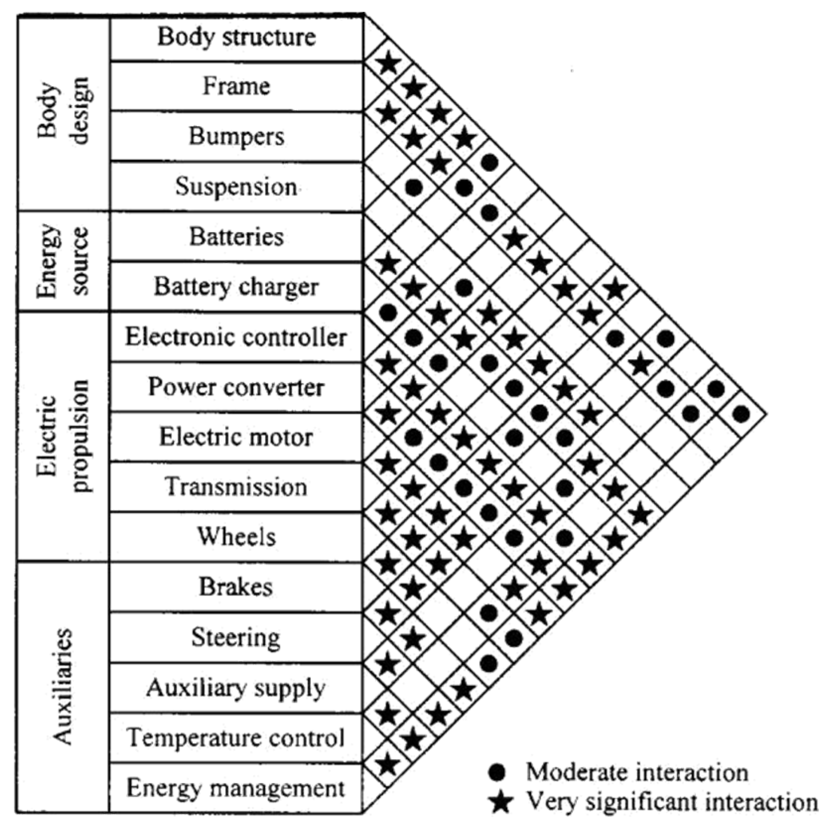
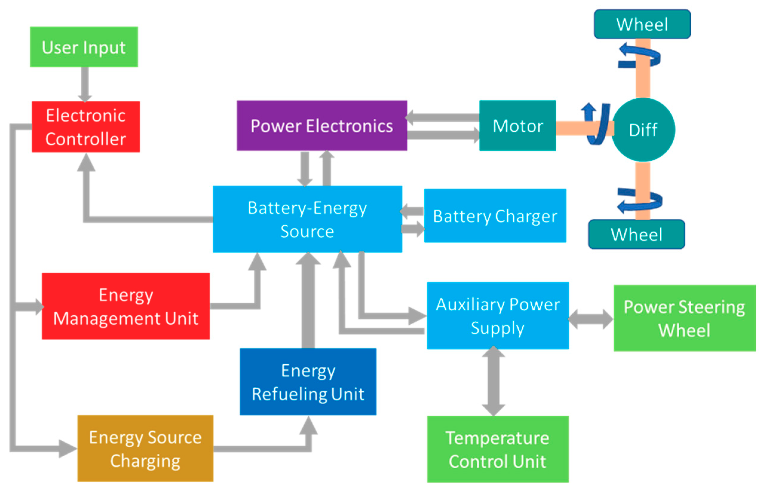
Pure Electric Vehicle Architecture

There are different feasible EV architecture systems due the variations in electric drive systems [55,60,62]. Six alternatives architecture that are possible in the EVs as shown in Figure 3. These six alternatives are illustrated in Figure 3.
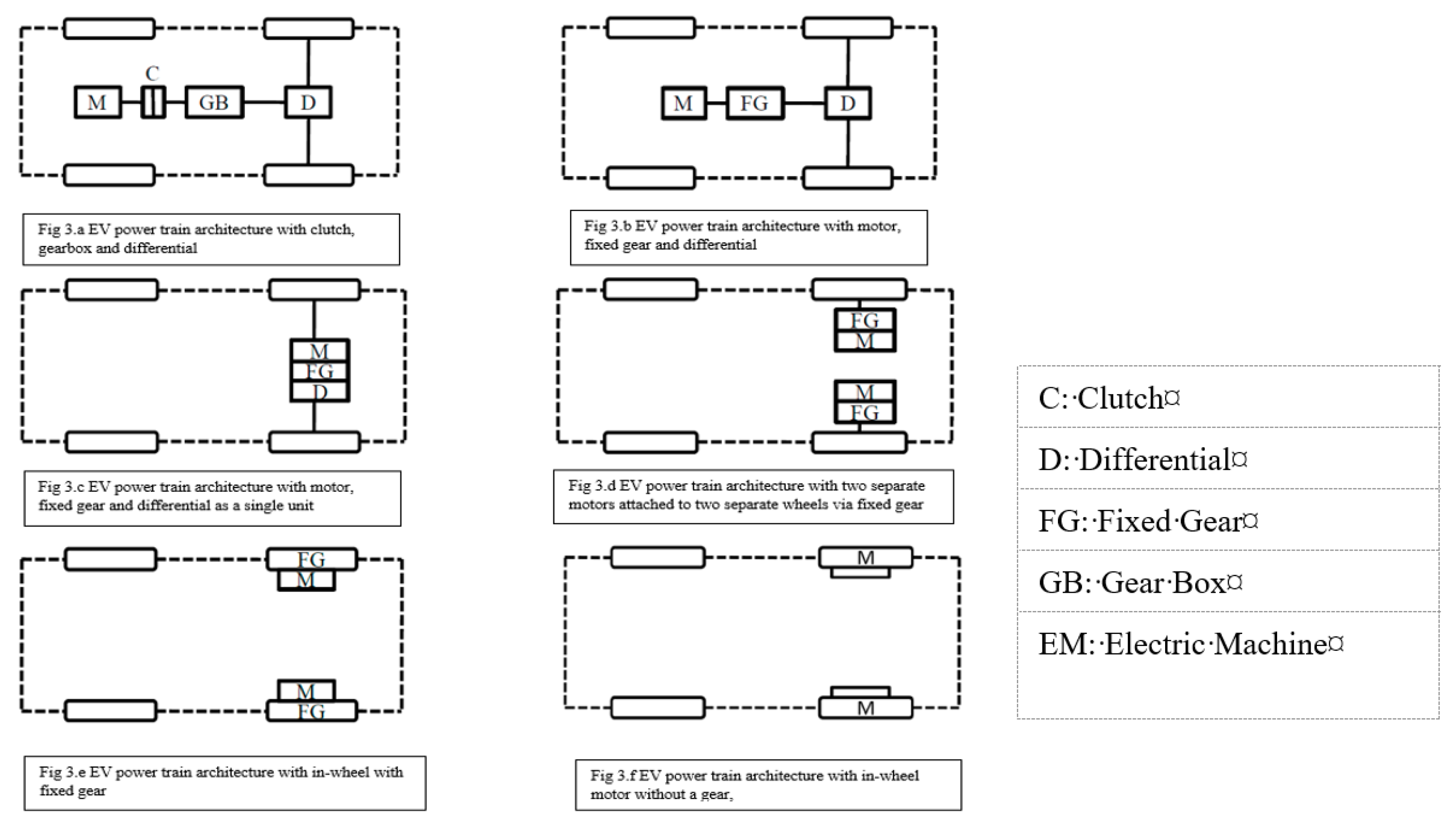
  • Figure 3a presents an electric motor architecture system which has an electric motor, a clutch (C), a gearbox, and a differential (D). The clutch engages or disengages the power flow from electric motor to the wheels like it does in internal combustion engine powered vehicles. The wheels have low speed with high torque in the lower gears and low torque with high-speed in the higher gears. This architecture setup was mostly used in conversion of ICE powered vehicles to EVs utilizing the existing components.
  • Figure 3b presents a single electric motor architecture with fixed gear. The advantage of this architecture is that the transmission weight is reduced as transmission and clutch have been omitted. Some vehicle conversion using electric machine without transmission system utilize this configuration.
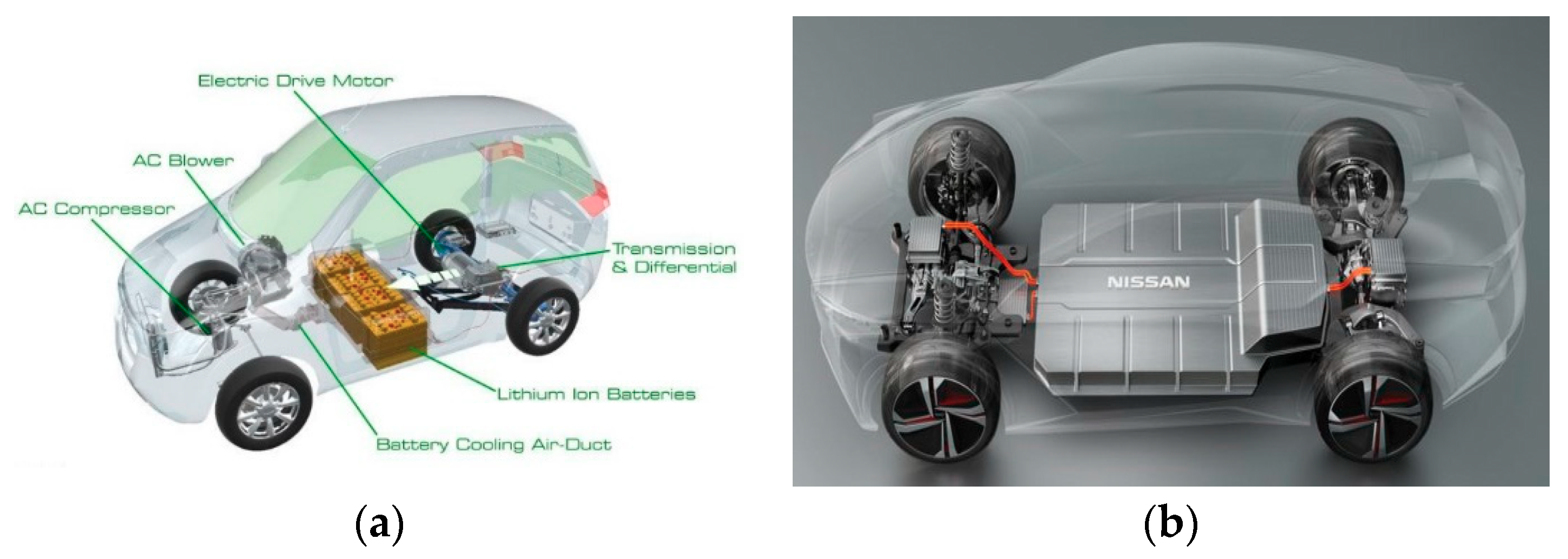
  • Figure 3c presents an EV architecture using one electric motor. It is an EM with rear wheel drive architecture with fixed gearing and differential integrated into a single assembly, and has been preferred by most of the electric vehicle manufactures at present scenario. Figure 4a shows similar rear wheel drive system used by Mahindra electric e20.
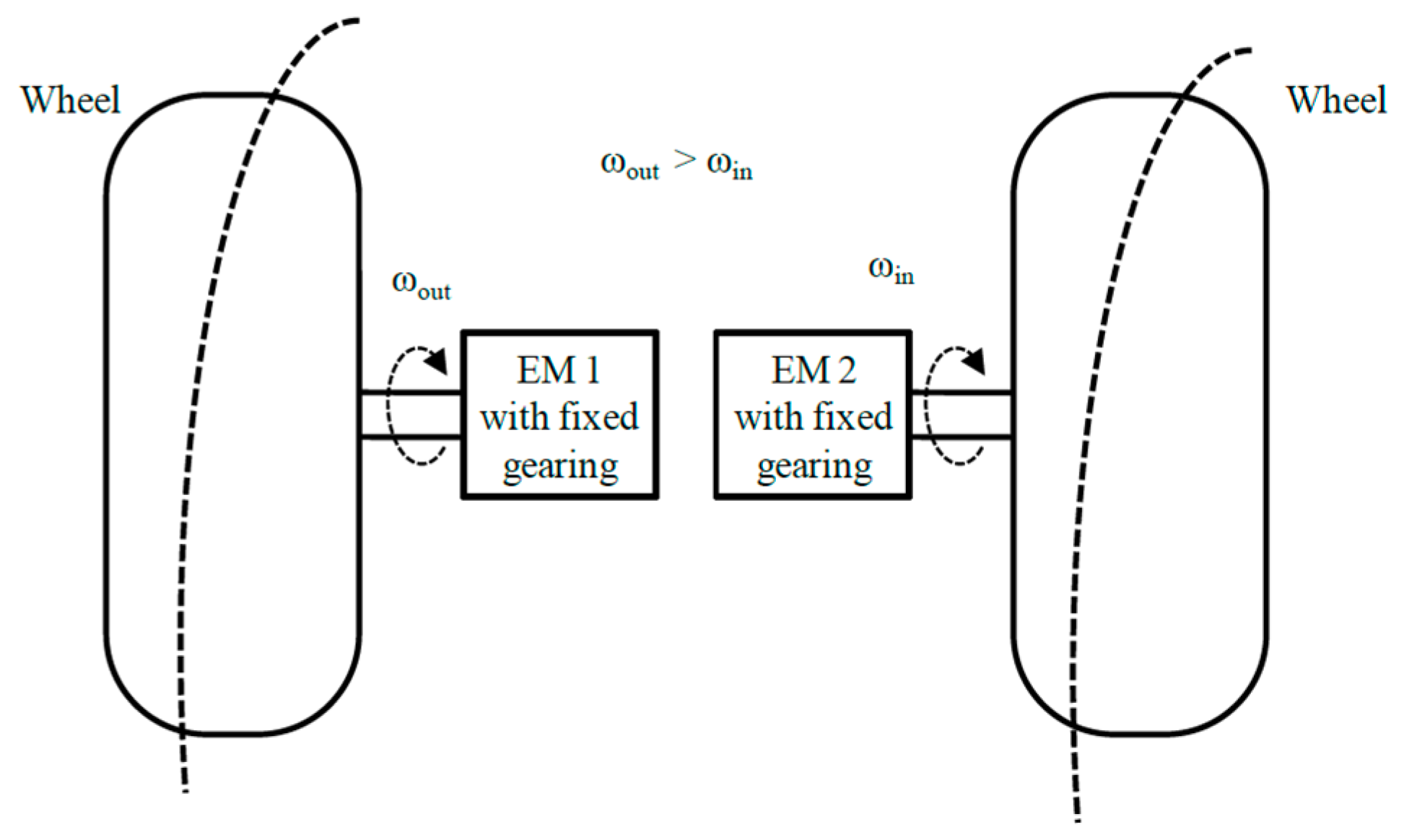
  • Figure 3d presents a dual-motor architecture. In this configuration, the differential action can be electronically controlled provided by two electric motors that operates at different speeds. In this dual-motor architecture, the driving wheels are derived separately by two separate electric motors separately via fixed gearing.
  • Figure 3e shows an architecture with a fixed planetary gearing system employed to reduce the motor speed to the desired wheel speed. This architecture is called an in-wheel drive system and the planetary gearing in this system offers the advantages of a high-speed reduction ratio along with an inline arrangement of input and output shafts [55,60].
  • Figure 3f presents an EV architecture without a mechanical gear system. A low-speed outer-rotor electric motor has been installed inside the wheels. The gearless arrangement with outer rotor mounted directly on the wheel rim makes equivalent speed control of the electric motor with the wheel speed and, hence, speed of the vehicle [64,65,66,67].
The above architecture set up depends on the required size and application of EVs, considering compactness, performance, weight, and cost of the vehicles. Presently, the popular configurations are as shown in Figure 3b or Figure 3c, mostly Figure 3c has been widely used in present electric vehicles to drive the both wheels using a single motor. The Nissan Leaf, Chevrolet Spark, Kona and Ioniq from Hyundai, Soul EV, Verito from Mahindra, and Niro from Kia uses front wheel drive system. While EVs can be built with the rear wheel drive system with the same configuration, the Tesla Model S, BYD E6, Reva, E20, E20 sport from Mahindra use rear wheel drive with single speed transmission to drive rear axle.
Figure 3e or Figure 3f have been used in project demos or production at lower scale. The Nissan Blade Glider involves a rear wheel drive system with in-wheel motor arrangement to the application of different amount of torques at two rear wheels to for better cornering performance.
All-wheel drive (AWD) architecture set up utilizes two motors to drive the front and two motors to drive the rear axles. An all-wheel drive architecture system is shown in Figure 4b. AWD configurations provide better traction control and avoids slipping. Torque vectoring can be used for better cornering performance [62,67,68,69]. AWD architecture systems with in-wheel motor systems can be utilized in cars like Nissan IMX as shown in Figure 4b providing an efficient driving performance.

4. Electric Propulsion

In electric vehicles, the electric motor utilizes the energy source from battery pack and converts the electric energy into mechanical power. The electric machine and drives combine as a single unit to form propulsion unit in electric vehicles to drive them.

4.1. Electric Machines and Drives

Electric machines are used for converting the energy from electrical to mechanical and vice versa. In electric vehicles, electric machines are used to provide power and torque to the transaxle for propulsion. The electric motor provides propulsive power in electric vehicles. The efficiency of energy conversion by electric machine is higher compared to internal combustion engine, in between 80–95% [70,71]. An electric motor provides high torque and high-power density with better torque characteristics at lower speed and the instantaneous power rating with two or three times the rated power of the motor [64]. The electric machines process the power in the reverse direction when turning the electric motors as generators. The braking mode can be termed as regenerative braking.
Electric vehicles have different electric machines and drives compared to electric machines and drives developed for industrial applications [72,73]. The electric propulsion system is the heart of pure electric vehicles, where electric machines and drives are the core technology for pure electric vehicle power train system that converts the electrical energy to the desired mechanical linear motion. The most electric vehicle comes with single speed reducer and most transmission systems are kept optional to drive the wheels. The stationary part stator and rotating part rotor of the electric motor play an important role in the overall performance of the motor technology [42,74].
The choice of an electric vehicle motor depends on the conditions defined by the three variables as shown in Figure 5. From Figure 5, we can realize that the three variables are vehicle requirement, vehicle restriction, and power source [63]. The vehicle requirements are defined by a drive cycle schedule. The vehicle restriction includes the type of vehicle, weight of vehicle, payload, and battery weight. Considering the above variables, we can choose a motor that satisfies the performance requirements of the vehicle.
Different electric motor exists. Two broad classes of electric machines for electric vehicles applications are: direct current (dc) and alternating current (ac) motors. The requirements for a motor to be used for an EV use include higher power and torque, variable range of speed e, higher efficiency, high reliability, and affordability. Direct current (DC) motor drives used to be earlier electric vehicles choice for the propulsion but inefficient unreliability made them less attractive [62] induction and permanent magnet (PM) types have become most favored ones with the advance development of their power electronic systems [75].

4.2. Brushed DC Motor Drive

DC motor drives were mostly used for propulsion system of electric vehicle (EV). Technological maturity and control simplicity made them usable for initial choice for driving EVs. DC motors have stators with permanent magnets (PM); rotors have brushes. For EV propulsion, the DC machine adopts the high-power density that it spins up to 5000 rpm and utilizes fixed gear (FG) system to step it down to 1000 rpm. A bulky, inefficient, and complicated reverse gear is avoided by offering reverse rotation [76,77].
Figure 6 shows the basic motor drive train system with different sub systems ranging from motor controller to single speed reducer differential and driving wheels. The stator integrates the field winding or permanent magnets (PMs) that helps in producing the magnetic field excitation, while the rotor installs the armature winding switched by the commutator through the carbon brushes. Figure 6 shows the basic set up of DC motor drives system to control the armature current and the output torque of the DC machine. In general, the feedback control variable is only the motor speed, while the armature current feedback is mainly for protection purposes [78].

4.2.1. Brushed DC Drive Control

For better control of speed of the DC drive system for their use in an electric vehicles DC–DC converters must be used. Two methods are employed for speed control of DC motors, drive armature voltage control and flux-weakening control. Pulse width modulation (PWM) is adopted for controlling application of the armature voltage of DC drive for EV propulsion [62,79,80]. On reducing the armature voltage of the DC motor, the armature current and the motor torque decrease, thereby decreasing the speed of the motor and increasing the armature voltage and the torque of the motor. When weakening the field voltage of the DC motor, the motor back EMF decreases. There is an increment of armature current by large value than its reduction in the field due to low armature resistance. Thus, the torque of the motor increases the motor speed [81,82].
From the Figure 7a,b, characteristic features of separately excited DC motors and series DC motor is shown. Below, the natural characteristics of the motors can operate for any torque-speed characteristics with constant slope against the change in speed. During the armature voltage control, maximum allowable armature current remains constant, the armature voltage control utilizes the advantage of maintaining the maximum torque, keeping the maximum allowable current constant at all speeds.
Dotted lines in Figure 7a,b represents the operation of separately excited DC motor and series DC motor during the weakening of the field voltage of the DC motor. During this control phenomenon, slope of both the dc motor characteristics varies but at the same time it is affected by the flux the independent armature voltage control and flux-weakening control, being applied to only separately excited DC motor drive system to achieve a wide range of speed control [78,82,83,84,85].

4.2.2. Application of DC Motor in Electric Vehicles

The separately excited DC and series DC motor drives have been widely adopted for EV drive systems. DC motor drives are no longer in use for driving EVs due to their lower efficiency lower power density and the regular wear and tear of the carbon brushes and commutator.

4.3. Permanent Magnet Brushless DC Motor

Permanent magnets (PM) are the major materials of PM brushless motor drives. PM BLDC motors are PM AC machines with trapezoidal back-emf waveforms due to the concentrated windings that are used in the motor. As there are no windings in the rotor, there is no rotor copper loss, which makes it more efficient than induction motors. There is no loss of copper in the rotor due the absence of the winding, making it more efficient than available induction machine. The motor drive has light weight, smaller size, is reliable, and provides better torque and specific power with better heat dissipation. The PM BLDC motor system has less maintenance and a higher efficiency compared to the DC brushed motor system [78,86,87,88,89,90].
The major advantages of using PM BLDC motor are:
  • high-energy PMs, light weight, and lower volume providing higher power density offering higher efficiency due to the absence of copper loss;
  • better heat dissipation and cooling;
  • higher reliability due to lower heating and lower manufacturing defects.
The Figure 8 shows the basic structure of the PM brushless DC machine
The single-PMBLDC motor architecture system consists of a voltage-fed inverter, an electronic controller, and sensors. The position sensor ensures the synchronization of the current with the flux. The speed control is relatively simple by controlling the stator currents to align the rectangular current with trapezoidal flux.

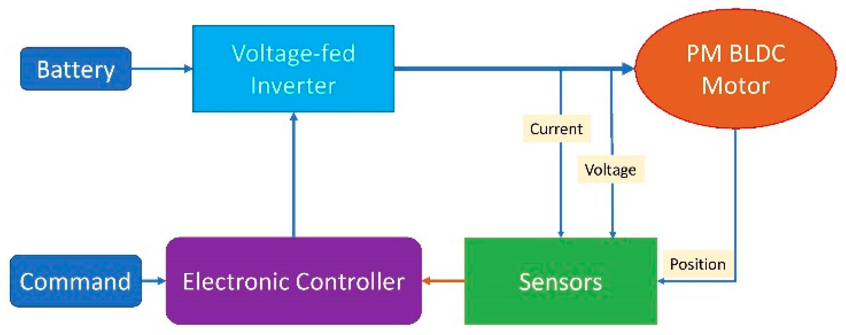
4.3.1. PM Brushless DC Motor Control

Rectangular AC current feeds the PM BLDC drive and has a significant torque pulsation. The stator flux and the rotor flux are kept close to 90° to drive PM BLDC motor, producing the maximum torque per ampere in the region of constant-torque operation. The phase-advance angle control offers operation of EVs with constant power. When the PM BLDC motor operates at speeds higher than the base speed due to the minor difference between the applied voltage and back EM, the PMBLDC motor runs out of time to engage the phase current while operating at a speeds higher than its base speed. From the Figure 9, it can be found that the operating region with constant power can be extended by increasing the phase-advance angle gradually [90,91,92,93].

4.3.2. Application of PM BLDC Motor in Electric Vehicle

PM BLDC motor has been the primary choice for use in electric vehicle applications. We can find most of the in-wheel hub BLDC motors in two-wheeler, fixed gear drive three-wheeler, and electric vehicle conversion kits. These days, BLDC motors are mostly commonly used in two-wheeler and three-wheeler vehicles.
There are two different kind of BLDC motors:

Out-Runner Type BLDC Motor

In out-runner BLDC motors, the position of the rotor is outside while that of stator is inside. They are also known as ‘hub motors’ as their wheel is directly coupled to the exterior rotor. External gear systems have no presence, while some offer a planetary gear system. As the motor is directly coupled to the rotor, there is no need of space for mounting the motors. These types are mostly common in electric bicycle, scooters, and in-wheel drive electric vehicles.

In-Runner Type BLDC Motor

In-runner BLDC motors come with the opposite configuration of out-runner BLDC by placing the rotor inside and stator outside. In order to transfer the power to the wheels, these systems require external transmission systems like that of fixed gear or chain drives.

4.3.3. Permanent Magnet Synchronous Motor (PMSM)

Permanent magnet synchronous motors have sinusoidal magnetomotive force (mmf), voltage, and current waveforms. When the sinusoidal distribution of the air-gap flux and stator windings is arranged, the machine operates as a synchronous machine. The rare earth magnet material in this motor drive helps to increase the flux density in the air-gap, the motor power density, and torque-to-inertia, and thus can be operated over a wide constant power speed range. The most common type of magnet materials that have been used in PM machines are ferrites, samarium cobalt (SmCo), and neodymium-iron-boron (NdFeB) [94,95,96,97,98,99]. The working mechanism is identical to BLDC motor except the sinusoidal wave form of the back EMF.
The major advantages of PMSM are:
  • efficiency is higher compared to brushless DC motors,
  • absence of torque ripple when the motor is commutated,
  • better performance with the higher torque,
  • reliable and less noisy,
  • performance is high in both higher and lower speed of operation,
  • easy to control due to lower inertia of the rotor,
  • heat dissipation is efficient,
  • smaller in size.

4.4. PMSM Motor Control

There are three different ways of controlling the PMSM motor, they are:
(a)
Field-Oriented Control (FOC)
A PM synchronous motor can utilize control strategies employed by induction motors such as FOC and direct torque control. The FOC has been utilized to the PM synchronous motor for driving EVs, PM field excitation in the PM synchronous motor deviates PMSM from induction motor.
(b)
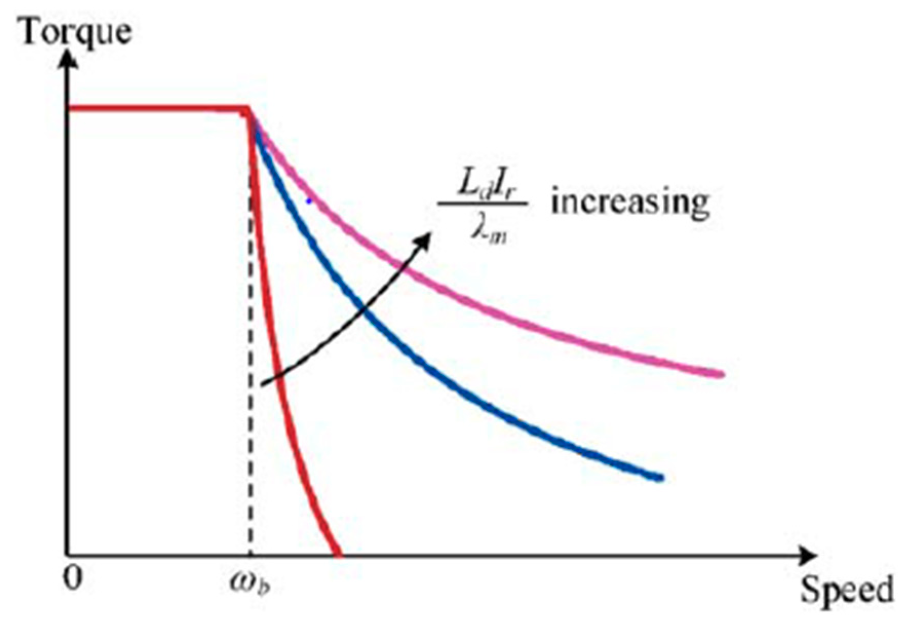
Flux-Weakening Control (FWC)
The terminal voltage equals the rated voltage at the base speed of PMSM. As back EMF grows with the speed, the extension of speed range is possible only when the air-gap flux is reduced, the so-called flux-weakening operation. Thus, the torque decreases while the speed increases, thus operating in constant power.
The Figure 10 shows the torque-speed capabilities of the PM synchronous motor. It can be found that the higher the Ld Ir/λm ratio is adopted, the better the flux-weakening capability can be achieved.
(c)
Position Sensorless Control (PSC)
This position sensor in the PMSM is for its control system and is usually based on an optical encoder. A PM synchronous motor with a position sensor is seldom adopted for driving EVs.

Application of PMSM Drive in Electric Vehicles

PMSM motors have been the preferred choice in EV drive trains due to their higher power density and efficient control system.

4.5. Induction Motor System

Induction motors are simple in construction, due to their reliability, lower maintenance, lower cost, and ability to operate in hostile environments. There are two types of induction machines (IMs): the wound-rotor and squirrel-cage. The wound-rotor induction motor is less attractive than the squirrel-cage counterpart—especially for electric propulsion in electric vehicles (EVs)—due to high cost, need for maintenance, and lack of sturdiness. Therefore, the squirrel-cage induction motor can be named as the induction motor for EV propulsion [78,90,100,101,102]. The motors have the capacity to increase the limit for maximum speed, and higher rating of speed and develop high output due to absence of brush friction. By changing the voltage frequency, the speed of induction motor can be varied. Field orientation control (FOC) of induction motor can terminate its torque control from field control [103,104,105,106,107].

Induction Motor Control

The three major control system for induction motors are:
(a)
Variable-Voltage Variable-Frequency (VVVF) Control
It adopts with constant voltage control for frequencies below the rated frequency, and variable-frequency control with constant rated voltage for frequencies beyond the rated frequency. For very low frequencies, voltage is boosted to recoup the difference between the applied voltage and induced EMF.
From the Figure 11, it can be observed that there are three operating regions:
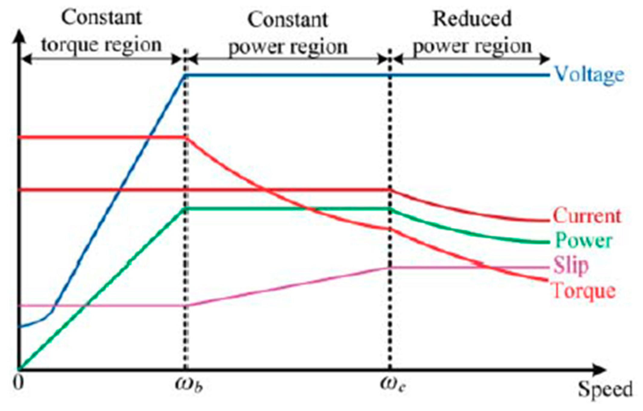
  • Below the rated speed, the motor delivers rated torque in constant torque region.
  • The slip is increased gradually to the maximum value at constant-power region with constant stator current and the motor runs with the rated power.
  • The slip remains constant in the reduced power region where there is decrement in stator current and the torque capability declines with the square of the speed.
(b)
Field-Oriented Control (FOC)
FOC for the induction motor drive can be implemented by:
  • The direct FOC, also known by the direct vector control, identifies the rotor flux linkage instantaneously by measuring the air-gap flux from stator voltage or current.
  • The indirect FOC, also known as indirect vector control, has been widely used in the induction motor drive for driving the EVs. This technique does not need to identify the rotor flux linkage.
(c)
Direct Torque Control (DTC)
The DTC provides the equivalent performance for the induction motor drive. This system selects the switching modes of the voltage-fed PWM inverter directly to controlling the stator flux linkage and the torque application of the induction machine in electric vehicles.
Most common motors used as the propulsion unit in EVs are IM because the design is simple and stable, with greater control and lower cost.

4.6. Switch Reluctance Motor

SRMs, also known as doubly salient motors, are synchronous motors and they are driven by unipolar inverter-generated current. SRM motors work on the principle of variable reluctance. SRMs is mostly suitable for high-speed operation without mechanical failure. Due to their high mechanical integrity, they are also suitable for driving EVs as in-wheel drive systems. However, they have the disadvantages of lower torque density, higher torque ripple, and larger acoustic noise [108,109,110].
The simple rotor structure is and does not require windings, magnets, commutators, or brushes, so it has rapid acceleration and immensely high-speed operation. Making it suitable for gearless operation in EV propulsion [111,112,113]. The current copping control (CCC) and the advance angle control (AAC) are the two main control systems for SR motor control systems. The speed boundary between these two control schemes is called the base speed, ωb, at which the back EMF is equal to the DC source voltage.

SRM Control System

The back EMF is lower than DC voltage below the base speed control system, the phase current can be regulated at the rated value, hence offers the constant-torque operation by regulating the phase current at rated speed. When the back EMF is higher than the DC source voltage above the base speed, the torque drops. When the back EMF increases with rotor speed decreasing, the phase current torque drops inversely to the rotor speed, in the AAC system running the SRM in constant power region, phase advancing is not possible beyond the critical speed of the motor, thus it operates in natural operation mode.
The Figure 12 shows the torque–speed profile in all three operating regions: constant torque operation, constant power region, and natural operating region application of SRMs in electric vehicles. The earliest first SR motor recorded one was built by Davidson in Scotland in 1838 for propelling a locomotive. Also, a lot of research and development projects are being carried out with application of SRM drive systems in electric propulsion systems [114,115].
Two major types of SR motor drives are illustrated for driving EVs. The first one is a SR with high-speed capable motor internally coupled with a planetary gear for speed reduction. The second one is a low-speed SR motor for in-wheel direct-drive configuration [62,113,116].
(a)
Planetary-Geared SR Motor Drive
During single-motor architecture system, the design of SR motor drive is focused for high-speed operation using a planetary gear synchronize the motor speed to wheel speed [62].
(b)
Outer-Rotor In-Wheel SR Motor Drive
To avoid the transmission gear and differential gear, in driving EVs the SR with an outer-rotor topology for low-speed operation are designed so as to directly drive each wheel.

4.7. Comparison of Existing EV Drives

EV drives are evaluated in considering their different parameters shown in following table [93].
In the Table 1, the demerit of the SR drive is the high acoustic noise, whereas the advantage of the induction drive is the low cost while the key merits of PM brushless drives are high power density and high efficiency. This evaluation indicates that the DC drive is undesirable, while the induction drive and the PM brushless drives are most favorable.
The Table 2 summarizes the application of existing drives in BEVs. For the DC drive, the application is undesirable in the current scenario, the application is rare for SR drive, the applications of the induction drive, and the PM Syn drive share the major market of EVsat current scenario.

4.8. Stator Permanent Magnet Motor

Stator-PM motor deviates itself from conventional permanent magnet (PM) brushless motor drives, with an advantage of all PM materials being located in the stator while the rotor with salient poles offers higher robustness with better thermal stability for PM materials [100].
For EV propulsion, there are three major stator motor types:
  • Doubly-salient permanent magnet (DSPM) machine
  • Flux-reversal permanent magnet (FRPM) machine
  • Flux-switching permanent magnet FSPM machine
Above all, the mentioned three types of stator-PM machines are based on PM excitation, and are classified as a group as uncontrollable but with the inclusion of independent field winding or magnetizing winding in the stator for flux control, the stator-PM machines become flux controllable, which can be further classified as:
  • Hybrid-excited permanent magnet (HEPM)
  • Flux-mnemonic permanent magnet (FMPM)
These flux-controllable techniques can be applied to form various topologies, such as the hybrid-excited flux-switching permanent magnet (HE-FSPM) machine or flux-mnemonic doubly-salient permanent magnet (FM-DSPM) machine.
The flux-controllable group, including the HE-DSPM (hybrid-excited doubly-salient permanent magnet), HE-FRPM (hybrid-excited flux-reversal permanent magnet), and HE-FSPM as well as the FM-DSPM, FM-FRPM (flux-mnemonic flux-reversal permanent magnet), and FM-FSPM (flux-mnemonic flux-switching permanent magnet) machines desire two external supplies, hence called the doubly-fed stator-PM machines.

Potential Application in Electric Vehicle

The stator-PM motor drives have high potentiality for EV application due to their capability of solving two fundamental problems of the existing PM motor drives:
  • Absence of PMs in the rotor, thus avoiding the problem of mounting them on the high-speed rotor and hence to withstand the high centrifugal force.
  • All PMs are located in the stator, with cooling arrangement and proving the thermal instability.
Concerning maturity for use in EV, the DSPM motor drive is the most favorable one because of its mature development for over two decades. Next, the FSPM and FRPM motor drives are decade-long mature technology. The HEPM and FMPM motor drives are immature technology as they are recently derived from the singly-fed stator-PM motor drives.

4.9. Advance Magnetless Motor

The absolute value and volatility of the neodymium price are uncertainty to the development of PM machines, and has revive the research of advanced magnetless machines. The induction machine and SRmachine can be considered as a magnet-less machines as they do not equip with any PMs but they do form their own respective families and the terminology ‘advanced’ is incorporated to deviate them from those magnetless machines that are recently developed or relatively immature [117,118,119,120,121]. Figure 13 shows the layout of power electronics components in a battery electric vehicle (BEV). The auxiliary supply provides the necessary power for equipment within the vehicle.
There are five majors advanced magnetless motor drives that are viable for EV propulsion, they are:
  • Synchronous reluctance (SynR)
  • Doubly-salient DC (DSDC)
  • Flux-switching DC (FSDC)
  • Vernier reluctance (VR)
  • Doubly-fed Vernier reluctance (DFVR)

Potential Application of Advance Magnetless Motor

Concerning maturity, the SynR and VR motor drives are relatively most mature technology because they have been developed for many decades, DSDC and FSDC motor drives are quite mature, have been developed for over a decade, and are considered to be most prominent magnetless motor drives, namely the DSPM and FSPM. The DFVR motor drive is immature technology recently derived from the VR motor drive, and the AFM machines are immature.

5. Power Electronics

System integration of power electronics is an effective to fulfill the cost and package volume requirements on pure electric vehicles. Power electronics plays the medium to transfer the information between the battery, a DC current source, and the drive motor.
A power converter device is necessary to regulate the power between the motor and the battery systems. The battery delivers current at a particular voltage. Power flowing into the battery needs to ensure of delivery of the correct voltage. Similarly, the power delivered by the battery must ensure the capability of electric machine to propel the vehicle. Algorithms of the control system specific to each type of motor always ensures its operation at the highest efficiency, typically between 95% and 98% [76]. Control strategies like model-referencing adaptive control (MRAC) and self-tuning control (STC), have been successfully applied to EV propulsion. Motor drives have also employed variable structure control (VSC) [76,83]. Fuzzy logic and neural networks have been employed to realize the concept of intelligent controllers with promising applications to EV propulsion. Progress has been made in magnetic components and capacitors for its use in high frequency power electronics. Still, many improvements need to be made; these are described in [122,123].
The power electronics components like diodes and switches should have resistance to both high temperature and high levels of vibrations. Improvements are required in capacitors and further investigation on the use of dielectric materials. Simplification of inverters is needed to integrate electromagnetic interference. Optimization of power electronics devices with higher heat resistance and the size optimization are required to make them more suitable for the EVs.

6. Transmission System

There are different research-based debates going on for battery electric vehicle regarding the use of single fixed gear transmission and multi transmission systems. Vehicles are specially designed to perform in different driving conditions—such as city, highway, and hilly—and thus electric propulsion motors should supply a wider range of speeds and torques to sync the demand that might force the traction motor to run outside its efficient operating region. To achieve better drivetrain efficiency and vehicle performance, transmission systems should be efficiently designed to integrate the electric power train system so that the EV can directly be driven by single motor, dual motor, transmission less, or there might be a single speed or multi speed transmission system between motor and wheel to optimize the vehicle performance [124]. Articles [125,126,127,128,129,130,131] describe the current studies on gearbox or alternative transmissions, multispeed transmission, and their use on EVS. Articles [132,133,134,135,136,137] discuss the use of multi-speed transmission systems on electric vehicles (EVs) including numbers of simulation-based comparisons with two-speed transmission systems, comparing single speed gearbox using different transmission system like CVT, AMT, and DCT.
Major EV manufacturers—like Tesla, Nissan, Hyundai, BYD, etc.—still use single-speed transmission systems as they help to minimize the associated cost, volume, energy loss, or drivetrain mass. However [138] describes, with the use of single speed transmission system, how EV powertrain performance significantly depends on the performance of electric motor that may not be efficient in all speed ranges while the use of a multi-speed transmission system may offer a real world solutions, keeping the electric motor efficient during the operation of EVs. In [139,140] they discuss how multi gear systems in EVs help in selecting smaller traction motors and batteries. Reference [132] mainly studies and compares the influence of the electric motor with fixed ratio system and the motor with a two-speed transmission system on the power and economy performance of the vehicle, based on a target vehicle, through the driving motor and drive train parameters matching, obtaining fixed ratio and two-speed transmission system respectively. References [132,141,142,143] studied the effect of two speed automatic transmission on the maximum speed, the maximum gradability, and energy consumption of pure electric vehicles on flat and straight road surfaces.

6.1. Multi-Motor Drive Transmission System

One can demolish the differential gears by using dual or multi EMs. Each wheel can be coupled to an EM enabling independent speed control of each wheel through multiple electric motors. In Figure 14, a dual-motor drive with an electronic differential is shown below [55,144].

6.2. In-Wheel Drive

Merits of minimizing the mechanical transmission path between the electric motor and the wheel through in wheel motor system is possible. In-wheel motor configuration reduces the drive train weight by avoiding the use of the central motor, associated transmission, differential, system, and subsystems [64]. Four-wheel drive improves the drivability of the vehicle by lowering the center of gravity of the vehicles [145].

7. EV Power Train Optimization with Performance Consideration

The performance indicators of conventional petrol or diesel vehicle includes economy, dynamic performance, braking performance, smooth performance, handling stability, and other related performances. The electric vehicles use electric machines as their propulsion system, their output performance of motor is different with conventional ICE vehicles, so the dynamic performance of the electric vehicle is quite different as compared with conventional vehicles. However, one cannot deny that the present electric vehicle developments have generally followed the approaches and the techniques used in conventional petrol/diesel powered vehicles. Most of the required parameters defined or applied on an electric vehicle are referenced from convention al ICE vehicles. Also, the performance of the electric vehicles must competitive with the conventional ICE vehicles so as to secure the transportation position as well as to attract new consumers. Therefore, we can say that the study of electric vehicle drive systems and improving the efficiency of the motor have a vital role in improving the overall performance of the electric vehicle [146,147]. To define the electric drive system, one needs to study the dynamic system, since this is the heart of the vehicle, it helps shape the performance of the vehicle. Strict calculation and parameter matching are required in the research process during the development of the power system so as to satisfy the requirement of vehicle dynamic performance.

7.1. Dynamic Performance

Due to the energy density and power density of battery power of the electric vehicle is still a challenging factor, depending on increasing the number of batteries because of size and weight—in design and development phase—selecting of power parameters and taking advantage of the performance of the various parts are very important in the same sense as the battery. Improving the dynamic performance and driving range of electric vehicles should be taken into consideration [148,149,150,151]. The great diversity of the present electric vehicle scenario and its potential greatness for future mobility depends on the consideration of technological optimization of motor, battery, and energy development during the design and application of electric vehicle. The dynamic system parameters should be matched to improve the performance of electric vehicle according to the requirements of road conditions [149].
The following are considered in designing and optimizing the size of power train system.

7.2. Drive Cycle

Driving cycles are vital instrument during the production of new vehicles and for the assessment of vehicle characteristics like vehicle powertrain sizing, energy consumption, and emissions. The standard drive cycles are used by the governmental agencies and automotive industry for the performance analysis of a vehicles. A drive cycle may have both speed and road gradient components, although typically one is held constant while the other is varied.
Table 3 shows the standard driving schedules [Iqbal, SAE J227a].
Table 3 describes the standard drive cycle J225asuggested by the Society of Automotive Engineers (SAE) to analyze the performance and energy source and very useful for design calculations related to develop the concept of an electric vehicles. It has three major schedules designed to simulate the typical driving patterns of fixed urban route (B), variable-route urban (C), and variable-route suburban travels (D).
Two most commonly used standard drive cycles are urban dynamometer driving cycle (UDDC) and highway fuel economy test (HWFET) to simulate urban and highway driving respectively. The other standard drive cycle as well like US06 standard drive cycle, new European drive cycle (NEDC), etc., to simulate different driving conditions. One should always consider the related drive cycle while defining the powertrain or optimizing the power train system, estimating energy consumption in electric vehicles.
Figure 15, Figure 16 and Figure 17 show the three different drive cycles.
Considering the related drive cycle, one should match the parameters for sizing the power train for design as well as for optimization.

7.3. Performance Parameters

Table 4 describes the different basic parameters of the vehicles needed to be matched for sizing the power train system as per performance requirement [149].
The data from different vehicle parameters of the above table undergoes different differential equations from vehicle dynamics to size the power train system as per defined performance requirements.

8. Future of Power Train System in Electric Vehicles

The adoption of EVs from the last few years has created a new vision for new feasible green mobility. The Figure 18 explains the recent data on global EV sales and the trends shows that more electric mobility is going to hit the market in coming years.
Also, Figure 18 shows that the trend is in positive domain despite 75 low sale in 2019. Global plug-in vehicle deliveries 2,264,400 units, in 2019 reached which is 9% higher than that of 2018. Europe became the beacon of 2019 EV sales with 44% growth, accelerating towards the end of the year [152,153]. The rise in different power train system and optimization system has boosted the electric vehicle sales.
The development of a concept city car like the Toyota i-Road to extreme off-road vehicles like the Tesla cyber truck, Bollinger Rivian R1T, etc. have provided real-world proof that future mobility depends on electric vehicles. More real-world concept vehicles might in the conceptual development stages. Formula E proves that electric cars can be powerful and can be racing cars as well.
EVs are the future of green mobility as even electric flying cars are being considered and are been manufactured. Even water way transport systems are now focusing on electric boats and, recently, an electric boat using Renault battery pack was demonstrated in Paris. Even the lunar roving vehicle used on the moon, known as moon buggies, were electric powered and NASA has been working on designs of different space exploring electric vehicles.
Different drive configured vehicles are expected to hit the market. All wheel drive system and electric motor with multiple transmission system might pick up their commercial use. In-wheel drive vehicles with better control mechanisms might be the next big game in electric mobility.

9. Discussion

The purpose of this paper is to focus on the power train system and subsystems of EV. Different technical findings are analyzed and the possibilities future trends of these sectors are discussed. The major findings of this paper are:
  • Different configurations are available for the drive train architecture in EVs. EVs can have front wheel drive, rear wheel drive, single motor drive, dual motor drive, or even all-wheel drive. In-wheel drive vehicles offer distinct advantages such as avoiding transmission as a major one. Different configuration of drive trains has not commercially penetrated now, but they do have scopes for use in future EVs.
  • Varieties of electric machines of different designs and configurations can be employed for use in EVs. Induction motors, permanent magnet synchronous motors, and synchronous reluctance motors are the eminent machines to propel EVs. Induction motors have been mostly used by present electric vehicles like Tesla and Mahindra Electric, while PMSM is currently being widely used with brands like Hyundai, Kia, BYD, etc. The next few years will be interesting to see the battle between induction and PMSM motors in electric drive trains.
  • Power electronics have developed to a great extent and different control systems have been produced and adopted for driving motors, managing energy, and charging the batteries. With increased penetration of new EV drive systems, energy sources, and charging technologies in the future, there will be greater oppostunities for more efficient control mechanisms.
  • Drive train optimization has been a trend for research. Consequently, efficient drive components could be developed. Different simulation tools have been in use for this approach for the design and optimization of the drive train, control unit, and sizing battery pack as well. Recently, multi speed transmission systems, especially two-speed transmission systems for EVs have been a hot topic, although major EV manufacturers are still using single speed fixed gear. In-wheel drive systems and their different configurations have been explained in order to avoid mechanical transmission systems. Most of the research has pointed the positive results with two-speed transmission systems when compared with fixed gear transmissions, as they can minimize the size of the drive train unit as well as increase the efficiency and advantages of in-wheel drive systems. Both of these systems may be in use in future EVs, but a lot of research and experiments in the real world might need to be undertaken as it adds weight and complexity to drive units, as well as adding control complexity to in-wheel drive systems.

10. Conclusions

Ecological development has raised concerns about green mobility. EVs are on the path of future green mobility, protecting the environment from global warming. Despite good sales figures of Tesla, Nissan leaf, and other electric vehicles, the commercialization of EVs is still not successful. The cost and range anxiety are the major obstacles that most EVs have been facing and have been improving upon in response to this challenge. Most of the research activities are focused on energy source improvements and development of efficient drive trains. The EV drive train configurations, motors, energy sources, power electronics, power train optimization scenario, and simulation technologies for EVs have been considered and discussed in depth. The key technologies of each section from different research papers have been reviewed and the different findings have been presented. The limitation of the present electric vehicles and the possible optimization technologies have been discussed with different data and analysis provided by different research papers on optimization. The present trends in EVs (ground, air, and water) and potential of future electric power train system developments have been discussed. Finally, the results of this paper in the form of a discussion have been presented to summarize the overall picture of this paper.

Author Contributions

Conceptualization, A.K. and S.P.; Methodology, A.K., S.B., and D.T.; Validation, S.B., D.T., and B.P.S.; Formal analysis, A.K. and S.P.; Investigation, A.K.; Resources, D.T. and S.B.; Writing—original draft preparation, A.K.; Writing—review and editing, S.P.; Supervision, D.T., S.B., and B.P.S. All authors have read and agreed to the published version of the manuscript.

Funding

This research received no external funding.

Acknowledgments

The authors would like to thank department of Mechanical Engineering, Kathmandu University for providing necessary facilities for the research work. Also, the authors are grateful to International Design Center, Massachusetts Institute of Technology, Boston, USA for providing the laboratory space and the continued support during the detailed study.

Conflicts of Interest

The authors declare no conflict of interest.

References

  1. Karki, A.; Shrestha, B.P.; Tuladhar, D.; Basnet, S.; Phuyal, S.; Baral, B. Parameters Matching for Electric Vehicle Conversion. In Proceedings of the 2019 IEEE Transportation Electrification Conference (ITEC-India), Bengaluru, India, 17–19 December 2019; pp. 1–5. [Google Scholar] [CrossRef]
  2. Yu, J.; Wang, J.; Liang, G.; Li, D. Pure electric vehicle driving system parameter matching in motor higher efficiency interval. In Proceedings of the 2012 International Conference on Systems and Informatics (ICSAI2012), Yantai, China, 19–20 May 2012; pp. 594–597. [Google Scholar] [CrossRef]
  3. Guo, X.; Fu, L.; Ji, M.; Lang, J.; Chen, D.; Cheng, S. Scenario analysis to vehicular emission reduction in Beijing-Tianjin-Hebei (BTH) region, China. Environ. Pollut. 2016, 216, 470–479. [Google Scholar] [CrossRef] [PubMed]
  4. Wu, Y.; Wang, R.; Zhou, Y.; Lin, B.; Fu, L.; He, K.; Hao, J. On-Road Vehicle Emission Control in Beijing: Past, Present, and Future. Environ. Sci. Technol. 2011, 45, 147–153. [Google Scholar] [CrossRef] [PubMed]
  5. Wu, Y.; Zhang, S.; Hao, J.; Liu, H.; Wu, X.; Hu, J.; Walsh, M.P.; Wallington, T.J.; Zhang, K.M.; Stevanovic, S. On-road vehicle emissions and their control in China: A review and outlook. Sci. Total Environ. 2017, 574, 332–349. [Google Scholar] [CrossRef]
  6. Netz, B.; Davidson, O.; Bosch, P.; Dave, R.; Meyer, L. Climate Change 2007: Mitigation. Contribution of Working Group III to the Fourth Assessment Report of the Intergovernmental Panel on Climate Change. Summary for Policymakers; Cambridge University Press: Cambridge, UK, 2007. [Google Scholar]
  7. Kathuria, V. Impact of CNG on vehicular pollution in Delhi: A note. Transp. Res. Part D Transp. Environ. 2004, 9, 409–417. [Google Scholar] [CrossRef]
  8. Faiz, A.; Ale, B.B.; Nagarkoti, R.K. The role of inspection and maintenance in controlling vehicular emissions in Kathmandu valley, Nepal. Atmos. Environ. 2006, 40, 5967–5975. [Google Scholar] [CrossRef]
  9. Raux, C. The use of transferable permits in transport policy. Transp. Res. Part D Transp. Environ. 2004, 9, 185–197. [Google Scholar] [CrossRef] [Green Version]
  10. Das, B.; Bhave, P.V.; Puppala, S.P.; Byanju, R.M. A global perspective of vehicular emission control policy and practices: An interface with kathmandu valley case, nepal. J. Inst. Sci. Technol. 2018, 23, 76–80. [Google Scholar] [CrossRef]
  11. Neeft, J.P.; Makkee, M.; Moulijn, J.A. Diesel particulate emission control. Fuel Process. Technol. 1996, 47, 1–69. [Google Scholar] [CrossRef]
  12. Chapman, L. Transport and climate change: A review. J. Transp. Geogr. 2007, 15, 354–367. [Google Scholar] [CrossRef]
  13. Kirchstetter, T.W.; Harley, R.A.; Kreisberg, N.M.; Stolzenburg, M.R.; Hering, S.V. On-road measurement of fine particle and nitrogen oxide emissions from light-and heavy-duty motor vehicles. Atmos. Environ. 1999, 33, 2955–2968. [Google Scholar] [CrossRef]
  14. Shrestha, R.M.; Kim Oanh, N.; Shrestha, R.; Rupakheti, M.; Rajbhandari, S.; Permadi, D.; Kanabkaew, T.; Iyngararasan, M. Atmospheric Brown Clouds: Emission Inventory Manual; United Nations Environment Programme: Nairobi, Kenya, 2013. [Google Scholar]
  15. Zhang, Y.; Stedman, D.H.; Bishop, G.A.; Guenther, P.L.; Beaton, S.P. Worldwide on-road vehicle exhaust emissions study by remote sensing. Environ. Sci. Technol. 1995, 29, 2286–2294. [Google Scholar] [CrossRef] [PubMed]
  16. Andwari, A.M.; Pesiridis, A.; Rajoo, S.; Martinez-Botas, R.; Esfahanian, V. A review of Battery Electric Vehicle technology and readiness levels. Renew. Sustain. Energy Rev. 2017, 78, 414–430. [Google Scholar] [CrossRef]
  17. McKinsey, A. Portfolio of Power-Trains for Europe: A Fact-Based Analysis; Tech. Rep.; McKinsey & Company: New York, NY, USA, 2010. [Google Scholar]
  18. Poullikkas, A. Sustainable options for electric vehicle technologies. Renew. Sustain. Energy Rev. 2015, 41, 1277–1287. [Google Scholar] [CrossRef]
  19. Wager, G.; Whale, J.; Braunl, T. Driving electric vehicles at highway speeds: The effect of higher driving speeds on energy consumption and driving range for electric vehicles in Australia. Renew. Sustain. Energy Rev. 2016, 63, 158–165. [Google Scholar] [CrossRef]
  20. Shafie-Khah, M.; Neyestani, N.; Damavandi, M.; Gil, F.; Catalão, J. Economic and technical aspects of plug-in electric vehicles in electricity markets. Renew. Sustain. Energy Rev. 2016, 53, 1168–1177. [Google Scholar] [CrossRef]
  21. Brasil, D. Provides for the New Stage of the Vehicle Emission Control Program-PROCONVE 20; Resolution No. 315; International Council on Clean Transportation: Washington DC, USA, 2002. [Google Scholar]
  22. Steinberg, I.; Nasdal, R.; Kurtzke, A. GETRAG 6HDT451:“Mild-Hybrid Including Wet-Running Dual-Clutch”. In Proceedings of the Vehicle Transmissions 2011, Friedrichshafen, Germany, 7–8 July 2011. [Google Scholar]
  23. Naunheimer, H.; Bertsche, B.; Ryborz, J.; Novak, W. Matching Engine and Transmission. In Automotive Transmissions; Springer: Berlin/Heidelberg, Germany, 2011; pp. 115–139. [Google Scholar]
  24. Yong, J.Y.; Ramachandaramurthy, V.K.; Tan, K.M.; Mithulananthan, N. A review on the state-of-the-art technologies of electric vehicle, its impacts and prospects. Renew. Sustain. Energy Rev. 2015, 49, 365–385. [Google Scholar] [CrossRef]
  25. Rana, L.B.; Shrestha, A.; Phuyal, S.; Mali, B.; Lakhe, O.; Maskey, R.K. Design and Performance Evaluation of Series Hybrid Electric Vehicle using Backward Model. J. Eng. 2020, 14, 1–10. [Google Scholar]
  26. Amjad, S.; Neelakrishnan, S.; Rudramoorthy, R. Review of design considerations and technological challenges for successful development and deployment of plug-in hybrid electric vehicles. Renew. Sustain. Energy Rev. 2010, 14, 1104–1110. [Google Scholar] [CrossRef]
  27. Shareef, H.; Islam, M.M.; Mohamed, A. A review of the stage-of-the-art charging technologies, placement methodologies, and impacts of electric vehicles. Renew. Sustain. Energy Rev. 2016, 64, 403–420. [Google Scholar] [CrossRef]
  28. Isobe, F.; Itakura, Y.; Osumi, Y.; Li, G. One Motor Type Electric Vehicle Drive System. Available online: https://www.ntnglobal.com/en/news/new_products/news201100027.html (accessed on 13 August 2020).
  29. Al-Alawi, B.M.; Bradley, T.H. Review of hybrid, plug-in hybrid, and electric vehicle market modeling studies. Renew. Sustain. Energy Rev. 2013, 21, 190–203. [Google Scholar] [CrossRef]
  30. Arora, S.; Shen, W.; Kapoor, A. Review of mechanical design and strategic placement technique of a robust battery pack for electric vehicles. Renew. Sustain. Energy Rev. 2016, 60, 1319–1331. [Google Scholar] [CrossRef]
  31. Hannan, M.; Hoque, M.; Mohamed, A.; Ayob, A. Review of energy storage systems for electric vehicle applications: Issues and challenges. Renew. Sustain. Energy Rev. 2017, 69, 771–789. [Google Scholar] [CrossRef]
  32. Tie, S.F.; Tan, C.W. A review of energy sources and energy management system in electric vehicles. Renew. Sustain. Energy Rev. 2013, 20, 82–102. [Google Scholar] [CrossRef]
  33. Peng, M.; Liu, L.; Jiang, C. A review on the economic dispatch and risk management of the large-scale plug-in electric vehicles (PHEVs)-penetrated power systems. Renew. Sustain. Energy Rev. 2012, 16, 1508–1515. [Google Scholar] [CrossRef]
  34. Phuyal, S.; Bista, D.; Bista, R. Challenges, Opportunities and Future Directions of Smart Manufacturing: A State of Art Review. Sustain. Futures 2020, 2, 100023. [Google Scholar] [CrossRef]
  35. Phuyal, S.; Izykowski, J.; Bista, D.; Bista, R. Internet of Things in Power Industry: Current Scenario of Nepal. In Proceedings of the International Symposium on Current Research in Hydropower Technologies (CRHT’IX), Dhulikhel, Nepal, 9 April 2019. [Google Scholar]
  36. Daniele, C. Limousine rivoluzionaria. Auto Des. 2001, 127, 64–67. [Google Scholar]
  37. Kawakami, K.; Kakizaki, Y.; Shimizu, H.; Norek, J.; Melotti, L. Design concept of high performance electric vehicle “KAZ”. Bull. Jpn. Soc. Sci. Des. 2003, 49, 27–36. [Google Scholar]
  38. Chan, C. The state of the art of electric and hybrid vehicles. Proc. IEEE 2002, 90, 247–275. [Google Scholar] [CrossRef] [Green Version]
  39. Fenton, J. Handbook of Vehicle Design Analysis; Professional Engineering Publication: London, UK, 1996. [Google Scholar]
  40. Shimizu, H.; Harada, J.; Bland, C. The role of optimized vehicle design and power semiconductor devices to improve the performance of an electric vehicle. In Proceedings of the International Symposium on Power Semiconductor Devices and IC’s (ISPSD’95), Yokohama, Japan, 23–25 May 1995; pp. 8–12. [Google Scholar] [CrossRef]
  41. van Gogh, D.; Shimizu, H. Concept of ‘KAZ’The Start of a New Generation in Car Design. In Proceedings of the 18th International Electric Vehicle Symposium, Berlin, Germany, 20–24 October 2011; pp. 190–191. [Google Scholar]
  42. Shrestha, A.; Phuyal, S.; Shrestha, P.; Mali, B.; Rana, L.B. Comparative Analysis of Regenerative Power and Fuel Consumption of Hybrid Electric Vehicle. J. Asian Electr. Veh. 2018, 16, 1799–1809. [Google Scholar] [CrossRef]
  43. Anderson, C.D.; Anderson, J. Electric and Hybrid Cars: A History; McFarland and Company Inc.: Jefferson, NC, USA, 2010; ISBN 978-0-7864-3301-8. [Google Scholar]
  44. Prem, A.; Bastien, C.; Dickison, M. Multidisciplinary Design Optimisation Strategies for Lightweight Vehicle Structures. Available online: https://core.ac.uk/download/pdf/231744324.pdf (accessed on 13 August 2020).
  45. Happian-Smith, J. An Introduction to Modern Vehicle Design; Reed Educational and Professional Publishing Ltd.: Oxford, UK, 2002. [Google Scholar]
  46. Grunditz, E.A.; Thiringer, T. Performance analysis of current BEVs based on a comprehensive review of specifications. IEEE Trans. Transp. Electrif. 2016, 2, 270–289. [Google Scholar] [CrossRef]
  47. Sae, S. Electric Vehicle and Plug in Hybrid Electric Vehicle Conductive Charge Coupler; SAE International: Warrendale, PA, USA, January 2010. [Google Scholar]
  48. Yilmaz, M.; Krein, P.T. Review of battery charger topologies, charging power levels, and infrastructure for plug-in electric and hybrid vehicles. IEEE Trans. Power Electron. 2012, 28, 2151–2169. [Google Scholar] [CrossRef]
  49. Suarez, C.; Martinez, W. Fast and Ultra-Fast Charging for Battery Electric Vehicles–A Review. In Proceedings of the 2019 IEEE Energy Conversion Congress and Exposition (ECCE), Baltimore, MD, USA, 29 September–3 October 2019; pp. 569–575. [Google Scholar] [CrossRef]
  50. Ronanki, D.; Kelkar, A.; Williamson, S.S. Extreme Fast Charging Technology—Prospects to Enhance Sustainable Electric Transportation. Energies 2019, 12, 3721. [Google Scholar] [CrossRef] [Green Version]
  51. Yilmaz, M. Limitations/capabilities of electric machine technologies and modeling approaches for electric motor design and analysis in plug-in electric vehicle applications. Renew. Sustain. Energy Rev. 2015, 52, 80–99. [Google Scholar] [CrossRef]
  52. Ashique, R.H.; Salam, Z.; Aziz, M.J.B.A.; Bhatti, A.R. Integrated photovoltaic-grid dc fast charging system for electric vehicle: A review of the architecture and control. Renew. Sustain. Energy Rev. 2017, 69, 1243–1257. [Google Scholar] [CrossRef]
  53. Kumar, M.S.; Revankar, S.T. Development scheme and key technology of an electric vehicle: An overview. Renew. Sustain. Energy Rev. 2017, 70, 1266–1285. [Google Scholar] [CrossRef]
  54. Weiss, M.; Patel, M.K.; Junginger, M.; Perujo, A.; Bonnel, P.; van Grootveld, G. On the electrification of road transport-Learning rates and price forecasts for hybrid-electric and battery-electric vehicles. Energy Policy 2012, 48, 374–393. [Google Scholar] [CrossRef]
  55. Ehsani, M.; Gao, Y.; Longo, S.; Ebrahimi, K. Modern Electric, Hybrid Electric, and Fuel Cell Vehicles; CRC Press: Boca Raton, FL, USA, 2018. [Google Scholar]
  56. Gao, Y.; Maghbelli, H.; Ehsani, M.; Frazier, G.; Kajs, J.; Bayne, S. Investigation of Proper Motor Drive Characteristics for Military Vehicle Propulsion; SAE International: Warrendale, PA, USA, 2003. [Google Scholar]
  57. Anderson, C.; Pettit, E. The Effects of APU Characteristics on the Design of Hybrid Control Strategies for Hybrid Electric Vehicles; SAE International: Warrendale, PA, USA, 1995. [Google Scholar]
  58. Fenton, J.; Hodkinson, R. Lightweight Electric/hybrid Vehicle Design; Elsevier: Amsterdam, The Netherlands, 2001. [Google Scholar]
  59. Zhang, L.; Li, L.; Qi, B.; Song, J. Configuration Analysis and Performance Comparison of Drive Systems for Pure Electric Vehicle; SAE International: Warrendale, PA, USA, 2015. [Google Scholar]
  60. Husain, I. Electric and Hybrid Electric Vehicles: Design Fundamentals; CRC Press: Boca Raton, FL, USA, 2011. [Google Scholar]
  61. Lee, C.H.T.; Chau, K.T.; Liu, C.; Chan, C.C. Overview of magnetless brushless machines. IET Electr. Power Appl. 2017, 12, 1117–1125. [Google Scholar] [CrossRef]
  62. Un-Noor, F.; Padmanaban, S.; Mihet-Popa, L.; Mollah, M.N.; Hossain, E. A comprehensive study of key electric vehicle (EV) components, technologies, challenges, impacts, and future direction of development. Energies 2017, 10, 1217. [Google Scholar] [CrossRef] [Green Version]
  63. Nasar, S.A.; Unnewehr, L.E. Electromechanics and Electric Machines; John Wiley & Sons: Hoboken, NJ, USA, 1983. [Google Scholar]
  64. Tahami, F.; Kazemi, R.; Farhanghi, S. A novel driver assist stability system for all-wheel-drive electric vehicles. IEEE Trans. Veh. Technol. 2003, 52, 683–692. [Google Scholar] [CrossRef]
  65. Lampic, G.; Slivnik, T.; Detela, A. Holistic approach in developing propulsion for urban electric vehicles. In Proceedings of the 2005 IEEE Vehicle Power and Propulsion Conference, Chicago, IL, USA, 7 September 2005; p. 5. [Google Scholar] [CrossRef]
  66. Heim, R.; Hanselka, H.; El Dsoki, C. Technical potential of in-wheel motors for Electric Vehicles. ATZ Worldw. 2012, 114, 4–9. [Google Scholar] [CrossRef]
  67. Fraser, A. In-wheel electric motors. In Proceedings of the 10th International CTI Symposium, 9–12 May 2016; pp. 12–23. [Google Scholar]
  68. Biček, M.; Gotovac, G.; Miljavec, D.; Zupan, S. Mechanical failure mode causes of in-wheel motors. Stroj. Vestn. J. Mech. Eng. 2015, 61, 74–85. [Google Scholar] [CrossRef] [Green Version]
  69. Chan, C.; Chau, K. Modern Electric Vehicle Technology; Oxford University Press: Oxford, UK, 2011; ISBN 019-850-416-0. [Google Scholar]
  70. Lebeau, K.; Van Mierlo, J.; Lebeau, P.; Mairesse, O.; Macharis, C. The market potential for plug-in hybrid and battery electric vehicles in Flanders: A choice-based conjoint analysis. Transp. Res. Part D Transp. Environ. 2012, 17, 592–597. [Google Scholar] [CrossRef]
  71. Cheng, M.; Sun, L.; Buja, G.; Song, L. Advanced electrical machines and machine-based systems for electric and hybrid vehicles. Energies 2015, 8, 9541–9564. [Google Scholar] [CrossRef] [Green Version]
  72. Chau, K. Electric motor drives for battery, hybrid and fuel cell vehicles. In Electric Vehicles: Technology, Research and Development; Nova Science: Hauppauge, NY, USA, 2009. [Google Scholar]
  73. Zhu, Z.-Q.; Howe, D. Electrical machines and drives for electric, hybrid, and fuel cell vehicles. Proc. IEEE 2007, 95, 746–765. [Google Scholar] [CrossRef]
  74. Chan, C.C.; Chau, K. An overview of power electronics in electric vehicles. IEEE Trans. Ind. Electron. 1997, 44, 3–13. [Google Scholar] [CrossRef] [Green Version]
  75. Rajashekara, K. Present status and future trends in electric vehicle propulsion technologies. IEEE J. Emerg. Sel. Top. Power Electron. 2013, 1, 3–10. [Google Scholar] [CrossRef]
  76. TW, C. Four-quadrant zero-current-transition converter-fed DC motor drives for electric propulsion. J. Asian Electr. Veh. 2006, 4, 911–917. [Google Scholar]
  77. Cornell, E.; Guess, R.; Turnbull, F. Advanced motor developments for electric vehicles. IEEE Trans. Veh. Technol. 1977, 26, 128–134. [Google Scholar] [CrossRef]
  78. Chau, K. Electric Vehicle Machines and Drives: Design, Analysis and Application; John Wiley & Sons: Hoboken, NJ, USA, 2015. [Google Scholar]
  79. Hayes, J.G.; Goodarzi, G.A. Electric Powertrain; John Wiley and Sons Ltd.: Hoboken, NJ, USA, 2018; ISBN 9781119063667. [Google Scholar]
  80. Unnewehr, L.E.; Nasar, S.A. Electric Vehicle Technology; The National Academies of Sciences, Engineering, and Medicine: Washington DC, USA, 1982; p. 232. [Google Scholar]
  81. Vas, P. Electrical Machines and Drives: A Space-Vector Theory Approach; Oxford University Press: New York, NY, USA, 1992. [Google Scholar]
  82. Dubey, G.K. Power Semiconductor Controlled Drives; Prentice Hall Publications: Englewood Cliffs, NJ, USA, 1989. [Google Scholar]
  83. Xue, X.; Cheng, K.; Cheung, N. Selection of electric motor drives for electric vehicles. In Proceedings of the 2008 Australasian Universities Power Engineering Conference, Sydney, Australia, 14–17 December 2008; pp. 1–6. [Google Scholar]
  84. Hua, G.; Lee, F.C. Soft-switching techniques in PWM converters. IEEE Trans. Ind. Electron. 1995, 42, 595–603. [Google Scholar] [CrossRef]
  85. Say, M.G.; Taylor, E.O. Direct Current Machines; Pitman: London, UK, 1986. [Google Scholar]
  86. Cody, J. Regenerative Braking Control for a BLDC Motor in Electric Vehicle Applications. Bachelor’s Thesis, University of South Australia, School of Electrical and Information Engineering, Adelaide, Australia, 2008. [Google Scholar]
  87. Emadi, A. Handbook of Automotive Power Electronics and Motor Drives; CRC Press: Boca Raton, FL, USA, 2017. [Google Scholar]
  88. Su, G.-J.; McKeever, J.W.; Samons, K.S. Design of a PM brushless motor drive for hybrid electrical vehicle application. In Proceedings of the PCIM 2000 Conference, Boston, MA, USA, 1–5 October 2000. [Google Scholar]
  89. Cody, J.; Göl, Ö.; Nedic, Z.; Nafalski, A.; Mohtar, A. Regenerative Braking in an Electric Vehicle. Available online: http://www.komel.katowice.pl/zeszyty.html (accessed on 13 August 2020).
  90. Rahman, K.M.; Ehsani, M. Performance analysis of electric motor drives for electric and hybrid electric vehicle applications. In Proceedings of the Power Electronics in Transportation, Dearborn, MI, USA, 24–25 October 1996; pp. 49–56. [Google Scholar] [CrossRef]
  91. Chan, C.; Xia, W.; Jiang, J.; Chan, K.; Zhu, M. Permanent magnet brushless drives. IEEE Ind. Appl. Mag. 1998, 4, 16–22. [Google Scholar] [CrossRef] [Green Version]
  92. Safi, S.; Acarnley, P.; Jack, A. Analysis and simulation of the high-speed torque performance of brushless DC motor drives. IEE Proc. Electr. Power Appl. 1995, 142, 191–200. [Google Scholar] [CrossRef]
  93. Krishnan, R. Permanent Magnet Synchronous and Brushless DC Motor Drives; CRC Press: Boca Raton, FL, USA, 2017. [Google Scholar]
  94. Miller, T. Permanent Magnet and Reluctance Motor Drives; Oxford Science Publications: Oxford, UK, 1989. [Google Scholar]
  95. Gieras, J.F. Permanent Magnet Motor Technology: Design and Applications; CRC Press: Boca Raton, FL, USA, 2002. [Google Scholar]
  96. Sebastiangordon, T.; Slemon, G.R. Operating limits of inverter-driven permanent magnet motor drives. IEEE Trans. Ind. Appl. 1987, 327–333. [Google Scholar] [CrossRef]
  97. Chin, Y.; Soulard, J. A permanent magnet synchronous motor for traction applications of electric vehicles. In Proceedings of the IEEE International Electric Machines and Drives Conference (IEMDC’03), Madison, WI, USA, 1–4 June 2003; pp. 1035–1041. [Google Scholar] [CrossRef]
  98. Magnussen, F. On Design and Analysis of Synchronous Permanent Magnet Machines for Field-Weakening Operation in Hybrid Electric Vehicles; Elektrotekniska System, Royal Institute of Technology: Stockholm, Sweden, 2004. [Google Scholar]
  99. Kommula, B.N.; Kota, V.R. Direct instantaneous torque control of Brushless DC motor using firefly Algorithm based fractional order PID controller. J. King Saud Univ. Eng. Sci. 2020, 32, 133–140. [Google Scholar] [CrossRef]
  100. Yamada, K.; Watanabe, K.; Kodama, T.; Matsuda, I.; Kobayashi, T. An efficiency maximizing induction motor drive system for transmissionless electric vehicle. In Proceedings of the 13th International Electric Vehicle Symp, Osaka, Japan, 13–16 October 1996; pp. 529–536. [Google Scholar]
  101. Boglietti, A.; Ferraris, P.; Lazzari, M.; Profumo, F. A new design criteria for spindles induction motors controlled by field oriented technique. Electr. Mach. Power Syst. 1993, 21, 171–182. [Google Scholar] [CrossRef]
  102. Bose, B.K. Power Electronics and Motor Drives: Advances and Trends; Elsevier: Amsterdam, The Netherlands, 2010. [Google Scholar]
  103. Divan, D.M. The resonant DC link converter-a new concept in static power conversion. IEEE Trans. Ind. Appl. 1989, 25, 317–325. [Google Scholar] [CrossRef]
  104. Cheng, S.; Li, C.; Gong, H. Research on induction motor for mini electric vehicles. Energy Procedia 2012, 17, 249–257. [Google Scholar] [CrossRef] [Green Version]
  105. Nanda, G.; Kar, N.C. A survey and comparison of characteristics of motor drives used in electric vehicles. In Proceedings of the 2006 Canadian Conference on Electrical and Computer Engineering, Ottawa, ON, Canada, 7–10 May 2006; pp. 811–814. [Google Scholar] [CrossRef]
  106. Tabbache, B.; Kheloui, A.; Benbouzid, M. Design and control of the induction motor propulsion of an electric vehicle. In Proceedings of the 2010 IEEE Vehicle Power and Propulsion Conference, Lille, France, 1–3 September 2010; pp. 1–6. [Google Scholar] [CrossRef] [Green Version]
  107. Bohari, A.A.; Utomo, W.M.; Haron, Z.A.; Zin, N.M.; Sim, S.; Ariff, R.M. Improved FOC of induction motor with online neural network. WSEAS Trans. Power Syst. 2014, 9, 136–142. [Google Scholar]
  108. Abbasian, M.; Moallem, M.; Fahimi, B. Double-stator switched reluctance machines (DSSRM): Fundamentals and magnetic force analysis. IEEE Trans. Energy Convers. 2010, 25, 589–597. [Google Scholar] [CrossRef]
  109. Cameron, D.E.; Lang, J.H.; Umans, S.D. The origin and reduction of acoustic noise in doubly salient variable-reluctance motors. IEEE Trans. Ind. Appl. 1992, 28, 1250–1255. [Google Scholar] [CrossRef]
  110. Gallegos-Lopez, G.; Kjaer, P.C.; Miller, T.; White, G. Simulation study of resonant DC link inverter for current-controlled switched reluctance motors. In Proceedings of the Second International Conference on Power Electronics and Drive Systems, Singapore, 17–20 November 2003; pp. 757–761. [Google Scholar] [CrossRef]
  111. Husain, I.; Ehsani, M. Torque ripple minimization in switched reluctance motor drives by PWM current control. IEEE Trans. Power Electron. 1996, 11, 83–88. [Google Scholar] [CrossRef]
  112. Krishnan, R. Switched Reluctance Motor Drives: Modeling, Simulation, Analysis, Design, and Applications; CRC Press: Boca Raton, FL, USA, 2017. [Google Scholar]
  113. Miller, T.J.E. Switched Reluctance Motors and Their Control; Magna Physics Publishing and Clarendon Press: Oxford, UK, 1993. [Google Scholar]
  114. Lin, W.-M.; Hong, C.-M.; Chen, C.-H.; Chien, H.-C. Implementation of a DSP-based hybrid sensor for switched reluctance motor converter. Int. J. Energy Environ. 2010, 1, 841–860. [Google Scholar]
  115. Sun, X.; Diao, K.; Yang, Z.; Lei, G.; Guo, Y.; Zhu, J. Direct Torque Control Based on a Fast Modeling Method for a Segmented-Rotor Switched Reluctance Motor in HEV Application. IEEE J. Emerg. Sel. Top. Power Electron. 2019. [Google Scholar] [CrossRef]
  116. Kachapornkul, S.; Jitkreeyarn, P.; Somsiri, P.; Tungpimolrut, K.; Chiba, A.; Fukao, T. A design of 15 kW switched reluctance motor for electric vehicle applications. In Proceedings of the 2007 International Conference on Electrical Machines and Systems (ICEMS), Seoul, South Korea, 24–27 November 2007; pp. 1690–1693. [Google Scholar]
  117. Cruickshank, A.; Anderson, A.; Menzies, R. Theory and performance of reluctance motors with axially laminated anisotropic rotors. Proc. Inst. Electr. Eng. 1971, 118, 887–894. [Google Scholar] [CrossRef]
  118. Lawrenson, P.J.; Gupta, S. Developments in the performance and theory of segmental-rotor reluctance motors. Proc. Inst. Electr. Eng. 1967, 114, 645–653. [Google Scholar] [CrossRef]
  119. Lee, C.H.; Chau, K.; Chan, C.; Liu, C.; Ching, T.W. Development of Axial-Field Flux-Switching DC In-Wheel Motor Drive for Electric Vehicles. In Proceedings of the 20th International Conference on Electrical Engineering, Jeju, South Korea, 20–21 November 2014; pp. 1591–1596. [Google Scholar]
  120. Lee, C.H.; Chau, K.; Liu, C.; Lin, F. Design and analysis of a magnetless flux-switching DC-excited machine for wind power generation. J. Int. Counc. Electr. Eng. 2014, 4, 80–87. [Google Scholar] [CrossRef] [Green Version]
  121. Profumo, F.; Zhang, Z.; Tenconi, A. Axial flux machines drives: A new viable solution for electric cars. IEEE Trans. Ind. Electron. 1997, 44, 39–45. [Google Scholar] [CrossRef]
  122. Seaman, A.; Dao, T.-S.; McPhee, J. A survey of mathematics-based equivalent-circuit and electrochemical battery models for hybrid and electric vehicle simulation. J. Power Sources 2014, 256, 410–423. [Google Scholar] [CrossRef] [Green Version]
  123. Mokrani, Z.; Rekioua, D.; Rekioua, T. Modeling, control and power management of hybrid photovoltaic fuel cells with battery bank supplying electric vehicle. Int. J. Hydrog. Energy 2014, 39, 15178–15187. [Google Scholar] [CrossRef]
  124. Wang, H.; Song, X.; Saltsman, B.; Hu, H. Comparative Studies of Drivetrain Systems for Electric Vehicles; SAE International: Warrendale, PA, USA, 2013. [Google Scholar]
  125. Holdstock, T. Investigation into Multiple-Speed Transmissions for Electric Vehicles. Ph.D Thesis, University of Surrey, Guildford, UK, 2015. [Google Scholar]
  126. Bottiglione, F.; De Pinto, S.; Mantriota, G.; Sorniotti, A. Energy consumption of a battery electric vehicle with infinitely variable transmission. Energies 2014, 7, 8317–8337. [Google Scholar] [CrossRef] [Green Version]
  127. Spanoudakis, P.; Tsourveloudis, N.C. On the efficiency of a prototype Continuous Variable Transmission system. In Proceedings of the 21st Mediterranean Conference on Control and Automation, Chania, Greece, 25–28 June 2013; pp. 290–295. [Google Scholar] [CrossRef]
  128. Mantriota, G. Fuel consumption of a vehicle with power split CVT system. Int. J. Veh. Des. 2005, 37, 327–342. [Google Scholar] [CrossRef]
  129. Zhang, Z.; Zuo, C.; Hao, W.; Zuo, Y.; Zhao, X.; Zhang, M. Three-speed transmission system for purely electric vehicles. Int. J. Automot. Technol. 2013, 14, 773–778. [Google Scholar] [CrossRef]
  130. Da-Tong, Q.; Bao-Hua, Z.; Ming-Hui, H.; Jian-jun, H.; Xi, W. Parameters Design of Powertrain System of Electric Vehicle with Two-Speed Gearbox; Journal of Chongqing University: Shapingba District, China, 2015. [Google Scholar]
  131. Spanoudakis, P.; Tsourveloudis, N. Prototype variable transmission system for electric vehicles: Energy consumption issues. Int. J. Automot. Technol. 2015, 16, 525–537. [Google Scholar] [CrossRef]
  132. Yin, Y.; Yin, X.; Luo, W.; Sun, H. Comparison Research of Electric Vehicles Equipped with Fixed Ratio Gearbox and Two-Speed Gearbox. Int. J. Recent Adv. Mech. Eng. (IJMECH) 2017, 6, 2. [Google Scholar] [CrossRef]
  133. Gao, B.; Liang, Q.; Xiang, Y.; Guo, L.; Chen, H. Gear ratio optimization and shift control of 2-speed I-AMT in electric vehicle. Mech. Syst. Signal Process. 2015, 50, 615–631. [Google Scholar] [CrossRef]
  134. Sorniotti, A.; Pilone, G.L.; Viotto, F.; Bertolotto, S.; Everitt, M.; Barnes, R.; Morrish, I. A novel seamless 2-speed transmission system for electric vehicles: Principles and simulation results. SAE Int. J. Engines 2011, 4, 2671–2685. [Google Scholar] [CrossRef]
  135. Spanoudakis, P.; Tsourveloudis, N.; Koumartzakis, G.; Krahtoudis, A.; Karpouzis, T.; Tsinaris, I. Evaluation of a 2-speed transmission on electric vehicle’s energy consumption. In Proceedings of the 2014 IEEE International Electric Vehicle Conference (IEVC), Florence, Italy, 17–19 December 2014; pp. 1–6. [Google Scholar] [CrossRef]
  136. Elmarakbi, A.; Ren, Q.; Trimble, R. Modelling and analyzing electric vehicles with geared transmission systems: Enhancement of energy consumption and performance. Int. J. Eng. Res. Technol. 2013, 2, 1215–1254. [Google Scholar]
  137. Sorniotti, A.; Subramanyan, S.; Turner, A.; Cavallino, C.; Viotto, F.; Bertolotto, S. Selection of the optimal gearbox layout for an electric vehicle. SAE Int. J. Engines 2011, 4, 1267–1280. [Google Scholar] [CrossRef]
  138. Lukic, S.M.; Emado, A. Modeling of electric machines for automotive applications using efficiency maps. In Proceedings of the Electrical Insulation Conference and Electrical Manufacturing and Coil Winding Technology Conference, Indianapolis, Indiana, USA, 25 September 2003; pp. 543–550. [Google Scholar] [CrossRef]
  139. Liang, Q.; Tang, N.; Gao, B.; Chen, H. Optimal planning of the clutch slipping control for gear shift of 2-speed electric vehicle. In Proceedings of the 26th Chinese Control and Decision Conference (2014 CCDC), Changsha, China, 31 May–22 June 2014; pp. 1538–1543. [Google Scholar] [CrossRef]
  140. Di Nicola, F.; Sorniotti, A.; Holdstock, T.; Viotto, F.; Bertolotto, S. Optimization of a multiple-speed transmission for downsizing the motor of a fully electric vehicle. SAE Int. J. Altern. Powertrains 2012, 1, 134–143. [Google Scholar] [CrossRef]
  141. Walker, P.; Zhu, B.; Zhang, N. Powertrain dynamics and control of a two speed dual clutch transmission for electric vehicles. Mech. Syst. Signal Process. 2017, 85, 1–15. [Google Scholar] [CrossRef] [Green Version]
  142. Sorniotti, A.; Boscolo, M.; Turner, A.; Cavallino, C. Optimization of a multi-speed electric axle as a function of the electric motor properties. In Proceedings of the 2010 IEEE Vehicle Power and Propulsion Conference, Lille, France, 1–3 September 2010; pp. 1–6. [Google Scholar] [CrossRef]
  143. Zhou, X.; Walker, P.; Zhang, N.; Zhu, B.; Ding, F. The influence of transmission ratios selection on electric vehicle motor performance. In Proceedings of the International Mechanical Engineering Congress and Exposition, Houston, TX, USA, 9–15 November 2012; pp. 289–296. [Google Scholar] [CrossRef]
  144. Husain, I. Solutions Manual for Electric and Hybrid Vehicles; CRC Press: Boca Raton, FL, USA, 2003. [Google Scholar]
  145. Fujimoto, H.; Saito, T.; Tsumasaka, A. Motion Control and Road Condition Estimation of Electric Vehicles with two in-wheel Motors. In Proceedings of the 2004 IEEE International Conference on Control Applications, Taipei, Taiwan, 2–4 September 2004; Volume 2, pp. 1266–1271. [Google Scholar] [CrossRef]
  146. Gang, W. State and Development of Electric Cars in China. Available online: http://en.cnki.com.cn/Article_en/CJFDTotal-ZHBY200302014.htm (accessed on 13 August 2020).
  147. Fenzhu, J.; Feng, G.; Rong, Z. Parameter design for driving line of power train and study on driving range of EVS. J. Liaoning Tech. Univ. 2006, 25, 426–428. [Google Scholar]
  148. Zhou, M.; Zhao, L.; Zhang, Y.; Gao, Z.; Pei, R. Pure electric vehicle power-train parameters matching based on vehicle performance. Int. J. Control Autom. 2015, 8, 53–62. [Google Scholar] [CrossRef]
  149. Zhang, L.; Hao, G.; Yang, X.; Zhou, C. The Electric Vehicle Power Design and The Matching Characteristics Analysis of The Transmission System. Telkomnika Indones. J. Electr. Eng. 2013, 11, 6352–6357. [Google Scholar] [CrossRef]
  150. Zhu, Z.; Yin, C.; Zhang, J.-W. Genetic Algorithm Based Optimization of Electric Vehicle Powertrain Parameters. Available online: http://en.cnki.com.cn/Article_en/CJFDTotal-SHJT200411030.htm (accessed on 13 August 2020).
  151. Kang, H.; Dandan, Z. Study on Driving Motor of Pure Electric Vehicles Based on Urban Road Conditions. In Proceedings of the 2013 International Conference on Communication Systems and Network Technologies, Gwalior, India, 4–6 July 2013; pp. 839–842. [Google Scholar] [CrossRef]
  152. Irle, R. Global EV Sales for 2018–Final Results. Available online: https://www.ev-volumes.com (accessed on 7 July 2020).
  153. Kane, M. Global EV Sales For 2019 Now In: Tesla Model 3 Totally Dominated. Available online: https://insideevs.com/news/396177/global-ev-sales-december-2019/ (accessed on 7 July 2020).
Figure 1. Different subsystems and their interaction with electric vehicles [36].
Asi 03 00035 g001
Figure 2. Vehicle powertrain architecture.
Asi 03 00035 g002
Figure 3. Electric vehicle (EV) drivetrain architecture alternatives based on drivetrain configuration [53].
Asi 03 00035 g003
Figure 4. (a) Mahindra E20 with rear wheel drive with single motor using single speed transmission (b) all-wheel drive Nissan IMX.
Asi 03 00035 g004
Figure 5. Power train interfaces.
Asi 03 00035 g005
Figure 6. Basic configuration of DC motor drive.
Asi 03 00035 g006
Figure 7. (a) Characteristics of separately excited DC motor control, (b) characteristics of series DC motor control.
Asi 03 00035 g007
Figure 8. Basic set up of PMBLDC motor system.
Asi 03 00035 g008
Figure 9. Torque–speed capabilities of phase-advance angle control of PM BLDC motor.
Asi 03 00035 g009
Figure 10. Torque-speed capabilities of flux-weakening control of MMSM [78].
Asi 03 00035 g010
Figure 11. Capabilities of operating VVVF controlled induction motor [78].
Asi 03 00035 g011
Figure 12. Torque–speed capability of the SR motor [78].
Asi 03 00035 g012
Figure 13. Power electronics in electric vehicles.
Asi 03 00035 g013
Figure 14. Dual-motor drive with fixed gear system.
Asi 03 00035 g014
Figure 15. UDDS drive cycle.
Asi 03 00035 g015
Figure 16. HWFET drive cycle.
Asi 03 00035 g016
Figure 17. US 06 drive cycle.
Asi 03 00035 g017
Figure 18. Global EV sales [152].
Asi 03 00035 g018
Table 1. Evaluation of existing EV drives.
FactorsDCInductionSRPMSMPM BLDC
Power density233.54.55
Efficiency233.54.55
Controllability54344
Reliability35544
Maturity55454
Cost level45433
Noise level35255
Maintenance15555
Total2535303535
1-worst; 5-best.
Table 2. Application of existing drives in BEV (car/three-wheeler).
Drives TypesBEV Models
DCPanda Elettra from FIat, Citroen berlingo Electrique, reva G-Wiz DC, three-wheeled tempos
SRChloride Lucas, converted General Motor prototype, small pick-up prototytpe
Induction GM EV1, BMW Mini E, Tesla Roadster, Reva G-Wiz I, Mahindra Electric- E20 series, Verito, etc.
PMSMNissan leaf, Mitsubishi i-MiEV Focus Electric, Citroen C-Zero, Peugeot iOn ED, BYD e6, Hyundai-Kona and Ioniq, KIA Soul EV and Niro, MG ZS EV, etc.
PM BLDCSmart fortwo ED, three-wheel electric tuk-tuks, and some of Chinese electric cars.
Table 3. Standard driving Schedule, SAE J227a.
Test ParameterSAE J227a Schedule
BCD
Max. Speed, km/h (mi/hr)324872
Acceleration time, ta (s)191828
Cruise time, tcr (s)192050
Coast time, tco (s)4810
Brake time, tbr (s)599
Idle Time, Ti (s)252525
Total time (s)7280122
Approximate no. of cycles per mile4–531
Table 4. Basic vehicle parameters.
Basic Vehicle ParametersVehicle Performance IndicatorElectric Machines Basic Parameters
CURB weight (kg)Power performance parameters like Rated power
Gross weight (kg)Maximum Speed (km/h)Peak power
Wheelbase (mm)(0~50 km/h) Acceleration time (s)Rated speed
Wheel rolling radius (mm)Maximum climbable gradient (%)Maximum speed
Frontal area (m2)Endurance mileage (km)Tared torque
Transmission rfficiency Max. torque
Drag coefficient
Rolling resistance coefficient

