1. Introduction
The rheological behaviour of natural soils mixed with additives (sand, natural aggregates, lime, chemical stabilizers) for road structures, so called improved soils, has to be characterized according to the working technology and the dynamic compaction regime of the vibratory roller.
For this, depending on the location of the construction site, in Romania since 1998 and until now, the team of researchers and technicians set up for the compaction process’ optimisation has developed specific technologies for 12 sites belonging to the Pan-European N-V and S-E road, between Oradea and Constanţa. Thus, tests were performed on the construction sites of the Transylvania, Cluj-Oradea, Lugoj-Timisoara, and Bucharest-Constanţa highways, in order to identify the physical-mechanical, rheological and technological characteristics of the improved soil layers put into place. In this context, it is mentioned that the great variety of improved soils showed different rheological behaviour from one location to another, being identified composed of linear viscoelastic models, schematised as follows: Voigt–Kelvin, Maxwell, Hooke–Voigt Kelvin, Newton–Voigt Kelvin and Zener [
1,
2,
3,
4,
5,
6].
In addition, there were several situations of weak nonlinearity or hysteretic viscoelastic behaviour identified, with insignificant deviations from the dynamic response in the forced vibration regime of the vibratory roller [
7,
8,
9].
Based on the “in situ” experimental results and the numerical evaluations with the actual field data and vibratory rollers (Bomag, Dynapac, Amman, Caterpilar, Hamm), it was found that the dynamic response can be evaluated based on linear viscoelastic rheological models. In this case, the vibration compaction process is conditioned by the added elements to the natural soil consisting in the content of clay, sand, mineral aggregates with chemical or ecological stabilizers with dosages specific to the applied technology, that essentially modify the elasticity and viscosity of the road structures to be realised [
10,
11,
12,
13,
14,
15].
In vibratory compaction, natural and filling soils can be characterized by Voigt–Kelvin linear rheological models, depending on the dynamic response to compaction. The content of clay, sand, mineral aggregates with chemical or environmentally friendly stabilizers modifies, essentially, both the elasticity and the viscosity of the earth layers brought in on the site.
Following the many experiments made on at least 25 categories of land with chemical and/or environmentally friendly stabilizers, the conclusion was that the dynamic response of the vibrating compactor roller matches the Voigt–Kelvin linear viscoelastic model (90% of the cases) [
11,
12,
16,
17,
18].
Of all the experiments in the mentioned share, after each passage of the vibrating compactor roll, three cases where the elastic and viscosity coefficients, respective of the stiffness viscous damping c, were identified and they can be classified into layers of soil as follows:
soils with discrete variable stiffness after each passage of the vibrating roll and constant damping [
11,
12,
17,
19].
soils with discrete variable stiffness and damping after each passage (soils with more than 80% mineral aggregates with a grain of more than 16 mm) [
11,
13,
14,
16,
17,
20].
In situ and laboratory experiments were conducted on natural soils with admixtures of lime, cement, black pigment, natural or chemical liquid stabilizers were performed on two categories of construction sites [
14,
15,
20].
This article includes the synthesis of the parameter values of stiffness and damping for the three distinct situations, which offer significant and representative dynamic responses of the vibrating compactor roller.
The families of the response curves of the amplitude and generated force, in relation to the continuous variation of the excitation frequency and the discrete variation of stiffness and damping, after each passage over the same layer of soil, were plotted both by numerical simulation and experimentally in situ [
10,
11,
12,
16,
19].
The setup of the dynamic response functions that define the “picture” of the family of functional curves, for a vibrating roller–soil (earth layer) dynamic system in stationary conditions, shows mainly elastic, viscous or viscoelastic nature. Thus, by the determination of the in the field response characteristic, determining can be appreciated, “in situ”, for the rheological nature of the soil improved in the vibrating compaction process.
Currently, on the construction sites from Romania, practical procedures are established in order to control the compaction process of the improved soils and asphalt mixtures. These include compaction calibration tests on an experimental site, where the dynamic parameters of the vibratory roller are harmonized with the soil characteristics so that the following parameters to be achieved: the designed compaction degree, the dynamic elastic modulus and road layer stiffness after the last pass over the same layer.
According to the shape and positioning of the family of curves cover, through an adequate real time representation, it is possible to establish, “in situ”, the nature of the predominantly elastic- viscous behaviour or viscoelastic of the terrain.
2. Dynamic Response of the Vibrating Compactor Roller
For the Voigt–Kelvin linear model, the equivalent stiffness
k of the layer of soil at the vibrating roller–soil contact, the equivalent viscous damping
c and the harmonic disturbing force
F = F(t) = F0sinωt have been considered. The force amplitude is
F0 =
m0r
ω2, where
m0r is the static moment of the dynamic mass imbalance in the vibrating compactor roller. The mass of the compactor roller in motion is
m [
2,
3,
5,
14,
15].
The linear dynamic system (m,c,k) has a single degree of freedom and is driven by the harmonic disturbing force F(t). For each discrete variable parameter k, c or (k,c), the excitation frequency (pulse) is swept continuously by using the command and control system of the vibrator’s hydrostatic actuation.
Thus, the dynamic response curves can be plotted by numerical simulation with the parameters (
m,
c,
k) of the soil and (
m0r,
ω) of the vibrating roller, as well as the experimental response curves, by measuring the amplitude of the vibrations
A(ω,
k),
A(ω,
c),
A(ω,
k,
c) “in every detail” for each significant value of
ω [
2,
6,
8,
12,
16,
19].
The dynamic response functions parameterized by
k,
c and with the continuous variation of the excitation frequency are for the amplitude
A(ω,
k,
c) =
A(
ω) and for the maximum force transmitted to the soil
Q0(
ω,
k,
c) =
Q0(
ω), signifying the efficiency of the dynamic compaction process. The calculation relations for the response functions are in the form:
In compaction, the significant dynamic regimes are the following:
The resonance regime for , where , meaning that the condition needs to be fulfilled.
The post-resonance regime for , or at the limit . Practically, is adopted.
Resonance regime. The parameters and for have the following calculation relations:
(a) The amplitude of the vibration
at resonance is expressed as
where we take into account
and
, obtaining
or
(b) The amplitude (maximum value) of the force transmitted to the soil
at resonance may be calculated as follows:
where we introduce
the hysteretic damping and
, so that we obtain
Considering that
, where
is the fraction of the critical damping, for linear viscoelastic systems, we have:
Thus, can be calculated depending on the stiffness k and on the damping expressed by c, or .
Post-resonance regime. For the limit condition , the relations for A(ω, k, c) and Q0(ω, k, c) will be expressed as follows:
(a) Amplitude in post-resonance is given by the relation
i.e., in post-resonance conditions, the vibration amplitude is constant, regardless of the variation of stiffness or damping. For this reason, it is also called technological amplitude in the stable and even compaction process.
(b) Maximum transmitted force
is expressed as
or
We find that the force transmitted in post-resonance increased proportionally to the monotone increase in the excitation frequency as the technological parameter.
3. Dynamic Response to the Continuous Variation of the Excitation Frequency and Discrete Variation of Stiffness
After each passage, stiffness
k is modified, while the viscous damping
c is kept constant. This is specific to the soils with the following content: clay 50%, sand 10%, mineral aggregates 20%, water 20%, and admixtures 10% [
9,
11,
12,
13,
14,
15].
For the soils in this category, elastic and damping parameters were established after each passage over the same layer, in conditions of forced vibrations of a vibrating roller. Thus, for i = 1, 2, 3, 4, 5 successive passes on the same layer, the following parameters were measured: N/m, N/m, N/m, N/m, N/m, kgm, kg, rad/s.
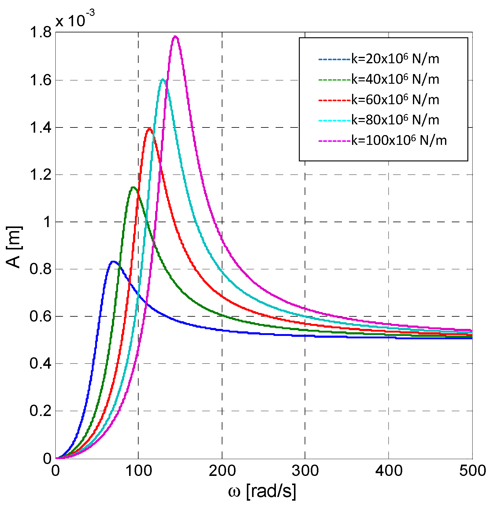
In these conditions, based on the relations (1) and (2), the response curves indicated in
Figure 1 and
Figure 2 were plotted.
If the viscosity coefficient c is constant, we find that, at resonance, the two parameters have different laws of variation, as follows:
(a) For the amplitude of the resonance vibrations, the calculation relation is expressed as
with the linear variation in relation to
, as we can see in
Figure 1. In this case, all the
amplitude resonance points are on a straight line in the system of axes
.
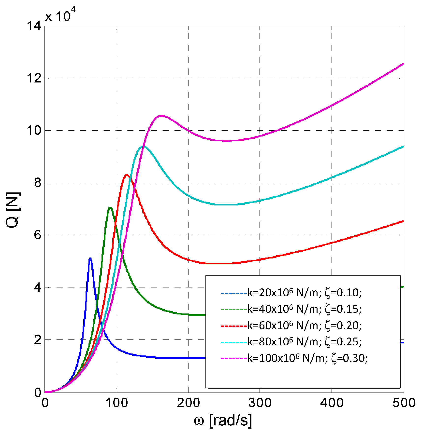
(b) For the amplitude of the force transmitted to the soil at the resonance
, the calculation relation in Formula (5) may be described as follows:
with the variation after a monotone ascending curve with the frequency
. We can see that all maxima of the force
are on curves parameterized by
k in the system of axes
, when the viscosity coefficient
c is constant (
Figure 2).
At the frequency of 30 Hz, “in situ” tests of the amplitude
A and the transmitted force
Q were performed for five categories of soil. Thus, the following experimental results were obtained, according to the families of curves presented in
Figure 1 and
Figure 2. These are: the amplitude
A = 0.56, 0.68, 0.81, 0.92 mm and the transmitted force
Q = 2.5, 3.5, 5.1, 7.2, 10.2 kN [
14,
15].
The experimental results were obtained on the Transylvania highway construction site, in Romania.
4. Dynamic Response to the Continuous Variation of the Excitation Frequency and Discrete Variation of Stiffness and Damping Coefficient
The approached case corresponds to the situation in which, after each passage of the vibrating roller over the same layer of soil, we can see the simultaneous change of both the stiffness ki, and the damping following the modification of the fraction of the critical damping after each passage i of the vibrating roller.
For the previous data and noting that at each passage
i, the critical damping fraction is modified, corresponding to the stiffness
ki is as follows:
,
,
,
,
[
13,
16,
19].
The graphical plotting of the amplitude curves depending on the variation of
and of the pair of parameters (
k,
), after each passage
i, with
i = 1.5, is given in
Figure 3.
For the maximum transmitted force
Q0 depending on the frequency
and the pair of values (
k,
), for each passage
i, with
i = 1.5, the curves in
Figure 4 were drawn.
Thus, for the discrete variation of the stiffness simultaneous with the viscous damping, in linear conditions, the following aspects can be mentioned:
(a) The resonance amplitude descends in relation to the increase in
for each gradual increment of the stiffness
k, respective of its specific frequency (pulse). Thus, for the discrete modification of the pairs of parameters (
), with
i = 1.5, we have
We can see that amplitude maxima, at resonance, are distributed according to an envelope curve with descending values of the resonance amplitude, with discrete
values for
i = 1.5, as indicated in
Figure 3.
(b) The force transmitted at resonance
, as seen in
Figure 4, can be assessed based on the relation
or in the form
which means that, at the increase in the values in the pair (
for
i = 1.5, the force
evolves according to a curve with the discrete values
, for
i = 1.5.
On the “Autostrada Soarelui” Bucharest-Constanța highway construction site, “in situ” experimental tests were performed, regarding the viscous-elastic behaviour of the composite soil used on this highway, corresponding to
Figure 3 and
Figure 4. The following results were obtained for the frequency of 30 Hz: the amplitude
A = 0.5, 0.502, 0.505, 0.509, 0.51 mm and the transmitted force
Q = 18, 31, 52, 75, 10.2, 100 kN [
2,
5,
14].
5. Conclusions
The research conducted both by rheological modelling and by laboratory and in situ testing has shown two categories of soils with markedly different compositions regarding vibration damping.
The obtained results are based on the studies and tests performed in Romania, on the road structures for the “Transylvania”, Brașov-Cluj-Oradea highway and the “Autostrada Soarelui” Bucharest-Constanța highway, as well as on the research performed by the specialists: Mooney, M.A., Rinehard, R.V., Wersäll, C., Larsson, S., Vucetic, M., Yoo, T.S. and Selig, E.T. [
6,
13,
21,
22,
23,
24,
25].
Thus, both for the soils categories used in Romania (the part presented in this paper), as well as for the experiments performed in the listed (quoted) papers, the laboratory equipment and the test methods were used specific to the geotechnical domain. For the “in situ” tests, test tracks were performed, specially designed and equipped to ensure the experimental conditions regarding the soil mixtures, the vibrating rollers, the instrumentation and the computer system for data acquisition, logging and processing.
The characteristic element is the fact that they have the same static stiffness after each passage of the vibrating compactor roller. The samples taken from the site were tested in the laboratory, in order to identify the elastic module and the stiffness. After each compaction passage with the vibrating roller, the stiffness k of the compacted layer and the damping expressed either by the viscous damping coefficient c or by the damping ratio were measured.
The adopted dynamic model is the Voigt–Kelvin model for both categories of soils, noting that, for the first category of compacted soil, the damping coefficient c stays constant during the whole compaction for the given successive passages of the vibrating roller, its value being Ns/m, while the stiffness is modified after each passage ki, i = 1.5.
For the second category of soil, the damping modifies after each passage, so the damping ratio has five values identified by experiment. In this case, for each passage, the layer of compacted soil will have a pair of numerical values of the parameters (, where i = 1.5. Therefore, the Voigt–Kelvin model will be characterized by discrete values for each passage over the same layer.
The response curves were plotted, i.e., the variation of the vibration amplitude for the same layer of soil. After each passage of the vibrating compactor roller, distinct dynamic responses are seen, depending on the nature of the soil, namely:
For soils with constant damping expressed by the viscous damping coefficient c, we find that, after each passage, the stiffness of the layer increases by discrete values, and the resonance vibration amplitude increases linearly with the growth of the resonance pulse (frequency).
For soils with increasing damping after each passage, expressed by the discrete increase in the damping ratio at the same time with the discrete increase in the compacted layer stiffness, we find that resonance vibration amplitude decreases in relation to the internal frequency, with the points of the resonance peaks arranged on a “characteristic” envelope curve.
The dynamic force transmitted to the compact soil layer has resonance peak values for both categories of soil, but with the arrangement of the points on different curves, depending on the nature of the soil, i.e., they arrange on “envelope” curves specific to each individual soil.
Based on the plotting of the response curves , in the case of dynamic compaction by vibrations and following the settlement of the “envelope” deemed envelope curve of the resonance amplitude peaks, we may assess the dissipative effect of the compacted soil, as well as its behaviour in the conditions of the compaction vibrations. Following the response values in the family of curves, we can determine the parameters of the Voigt–Kelvin model after each passage, namely and or and .
The parameters
k, c and
for the first category of soils with constant damping, based on the response curves plotted experimentally in situ (
Figure 1) in the compaction with a vibrating roller, can be calculated as follows:
;
i = 1.5 for each value of i = 1.5;
for each value of
i = 1.5;
for each value of
i = 1.5.
The parameters
and
for the second category of soils with different damping from one passage to the next one, based on the experimentally plotted response curves (
Figure 3), can be calculated as follows:
;
i = 1.5 for each value of
i = 1.5;
for each value of
i = 1.5;
for each value of
i = 1.5.
Given the abovementioned aspects, we can draw the conclusion that, depending on the family of response curves, the envelope curve can be shown as the geometric place of the amplitude peaks at resonance. Therefore, according to the nature of the soil, we can distinguish between two cases in which the envelope of the resonance points is the straight line indicating the ascending direction of the amplitude with its own frequency, and, on the other hand, the envelope, in the form of a curve, indicating the descending direction of the amplitude with its own frequency. Hence, the earth (soil) to be compacted can be classified as a defined rheological system and it can be “calibrated” based on the plotting of the envelope curves in the system with the parameters k, c or , according to one of the two described situations. In this context, the conceptual basis for two categories of technical specifications is constituted, approved by the Romanian Ministry of Regional Developments and Public Administration regarding the assessment of the capability level of dynamic compaction equipment for road construction works. On the other hand, the Research Institute for Construction Equipment and Technology—ICECON, from Bucharest, Romania, developed, in 2019, operational procedures for the optimization of the compaction process with vibratory rollers depending on the soil category on which the road structures are realised.
In essence, it is emphasized that the presented results are capitalized for engineering practical purposes.
A research program is currently being carried out with the aim of creating an intelligent system for the detecting, logging and processing of technological vibration signals, in real time, so that the response curves can be plotted using a specialized software. They have to ensure the compaction degree, the dynamic rigidity and the dynamic modulus of the compacted soil in correlation with the laboratory tests, so that the quality of the compaction process is able to be verified in real time.


