Article

Sustainable Acrylic Thermoplastic Composites via Vacuum-Assisted Resin Infusion Molding: Evaluation and Comparison of Fabrics and Recycled Non-Woven Carbon Fiber as Reinforcement

1
Department of Chemical Engineering Materials Environment, Sapienza University of Rome, 00184 Rome, Italy
2
INSTM Reference Laboratory for Engineering of Surface Treatments, UdR Rome, Sapienza University of Rome, 00184 Rome, Italy
*
Author to whom correspondence should be addressed.
J. Compos. Sci. 2025, 9(8), 441; https://doi.org/10.3390/jcs9080441
Submission received: 9 July 2025 / Revised: 13 August 2025 / Accepted: 15 August 2025 / Published: 17 August 2025
(This article belongs to the Special Issue Carbon Fiber Composites, 4th Edition)

Abstract

Recently, environmental issues have compelled people worldwide to pursue sustainability and adopt circular economy practices across all engineering sectors, including polymer engineering and composite fabrication. A transition towards fabric-reinforced thermoplastics (FRTPs), a greener solution, has been recommended in recent years. On the other hand, utilizing recovered reinforcing phases, such as recycled carbon fiber (rCF), has attracted tremendous attention. In this framework, the aim of this research is to investigate the performance of acrylic-based FRTPs (Elium® resin developed by Arkema). Woven virgin carbon fiber (vCF) and non-woven recycled carbon fiber (rCF) fabrics were used as reinforcement architectures for the fabrication of composites via resin infusion. The optimized formulation selected for the matrix showed flexural modulus and flexural strength of 5 GPa and 78 MPa, respectively. Composites prepared with woven vCF reached 36 GPa and 620 MPa values of flexural modulus and strength, respectively. The study of non-woven fabric is of particular interest, because the web is composed of recycled carbon fibers obtained from end-of-life (EoL) thermoset composite components. The results were promising; the flexural modulus reached 8 GPa, and the flexural strength was 113 MPa. Improvements are anticipated, especially in the parameters and conditions of the molding process.

1. Introduction

Sustainable development (SD) and the circular economy (CE), as current global objectives, have compelled academia and industries to alter policies and regulations across various fields, especially in two critical areas—composite waste management and composite production. So far, carbon fiber-reinforced composites (CFRPs) have been adopted in several sectors, such as aerospace, automotive, electrical energy generation, construction, and many more. Compared to metallic components, these composites offer several advantages, like resistance to corrosion, ease of process, cost-effectiveness, and lightweight while maintaining high mechanical performance [1]. Driven by their advantageous properties, the market for CFRPs has continued to expand, and it is expected to grow each year. As a result, the volume of decommissioned CFRPs will also be larger. For instance, statistics show that in Europe, the electrical power supplied by wind turbines, one of the sectors where CFRPs are mainly used, is projected to grow by 27% by 2030 and by 50% by 2050 [2]. Accordingly, a projected ~12% annual increase in composite waste generated by EoL wind turbine blades by 2026, followed by ~41% by 2034, is forecast [3]. Notably, a significant fraction of EoL CFRPs is either landfilled or incinerated, a typical destination in the linear economy (LE) approach where only the maximum value of an object during its service life is sought. These two disposal strategies are causing environmental problems, from groundwater contamination, micro/nano plastics formation, and air pollution to hazardous gas release, leading to climate change and global warming. On the contrary, shifting toward the SD and the CE approach makes it possible to transform waste into wealth. CFRP waste can be recycled, recovered, reused, or repurposed. Historically, it is believed that the lack of a proper route to recycle CFRP composites is because of the high production rate and high in-service technical demands, which resulted in focusing solely on performance and not on managing generated waste [4]. However, policies worldwide have forced individuals and industry to recycle and recover thermosets through three main pathways—mechanical, thermal, and chemical techniques. The investigation of these recycling strategies is beyond the scope of this work, but in-depth studies can be found in the literature [4,5,6,7,8,9].
Previous studies have declared that fibrous recyclates that have undergone recycling procedures exhibit inadequate properties as a reinforcing phase because of the downgrade in their physical, chemical, and mechanical integrity [10]. For instance, rCF reclaimed after the pyrolysis process might be damaged due to exposure to elevated temperatures or harsh atmospheres, such as oxidative ones, resulting in weaker performance compared to vCF, depending on processing conditions [11,12]. Therefore, fabricating new and innovative secondary materials using recovered fibers and preforms could be one of the most promising opportunities for further reuse in composite industry [13]. The term “non-woven fabric” has gained significant attention in recent decades due to its versatile applications and impressive features, such as energy absorption, drawability, electromagnetic shielding, and high productivity, which can be of high interest to the automotive sector [14,15,16,17]. Non-wovens are made from directionally or randomly oriented fibers (typically with lengths less than 100 mm) or filaments (with endless lengths). Several factors are crucial for the manufacturing of non-woven mats. Among these, web formation and web bonding are the most important. Many procedures have been introduced to create this specific type of fabric since its introduction (see Figure 1). One of the most common techniques to produce dry-laid, non-woven fabrics is the carding process as a web formation procedure, followed by needle-punching, where the fibrous web is converted into a complex interlocked 3D structure with the help of barbed needles [18].
CFRPs can be divided into two main families based on the nature of their matrices. These can be either thermosets or thermoplastics. Thermosets still hold a large share of the composite market while offering high mechanical performance and better matrix-reinforcement interfacial adhesion, and their molding techniques are cost-effective and well-established. Regardless of the counted benefits, waste management of thermoset composites is one of the most critical and challenging issues for which SD and CE objectives call for the consideration of other alternatives. For this reason, thermoplastics have regained prominence in academia and industry in the last few years, and their utilization has steadily increased ever since. Moreover, this kind of composite material provides benefits from high ductility and toughness, thermoformability, long storage time, repairability, and weldability to recyclability [19,20,21]. Unfortunately, apart from lower stiffness and poorer interfacial properties, thermoplastic composites have a dominant drawback. Properly impregnating continuous fibrous reinforcements with thermoplastic resins by conventional molding methods requires high temperatures and pressures, making it a hazardous choice for the environment, in addition to various technical and financial challenges. These issues are directly related to the high melt viscosity of thermoplastic resins. Traditionally, several solutions to this problem were suggested based on reducing the distance covered by the molten matrix phase, such as commingled yarns, matrix powder-impregnated fabric, and film stacking [22,23,24]. Furthermore, on other occasions, it was recommended to increase the processing temperature to decrease the viscosity. Yet, in this case, there would be a limitation in using natural fibers as reinforcement, given their low onset degradation temperature, entailing higher costs and technical difficulties [25].
A novel approach to addressing the aforementioned issues with thermoplastics is to adopt a method based on reactive processing; the fabric is impregnated with low-viscosity monomeric precursors, and the polymerization reaction then occurs “in situ” [26,27,28]. Recently, Arkema introduced the Elium® resin family, which can polymerize in situ at room temperature. This type of methyl methacrylate (MMA) monomeric thermoplastic resin reacts with benzoyl peroxide (BPO) initiators to start the polymerization [29]. Elium® 158O is one of the formulations of these MMA resins, composed of 2-propenoic acid, 2-methyl-, methyl ester and acrylic copolymers (not specified due to company confidentiality and trademark protection). Elium®-based composites not only have properties close to high-performance composites, but they are also easy to recycle, thermoform, and highly resistant to impact. Several studies have been conducted on this resin type and its relevant composite materials in recent years, including detailed and interesting reviews [25,30,31]. Shen et al. [32] recently proposed a methodology to find the trade-off between efficiency of the manufacturing process, sustainability, and the performance of Elium®-based composites.
Although some studies have been conducted on composites prepared with non-woven mats and epoxy systems by the vacuum-assisted resin infusion molding (VARIM) method [33,34], to the authors’ knowledge, there are no studies on thermoplastic composites produced with non-woven fabrics made from recycled carbon fibers by liquid infusion. Only recently, CIDER project partners announced on the web that they produced a demonstrator made with rCF and Elium® resin [35].
In this work, neat Elium® polymeric sheets with various initiator contents were fabricated. The sheets were characterized mechanically and thermally, and subsequently, the optimum formulation was chosen for composite production. Composites were produced using the VARIM technique; the reinforcements were plain-woven vCF fabric and a non-woven rCF mat from pyrolyzed composite wastes. The CFRPs were investigated mechanically, thermally, and morphologically.

2. Materials and Methods

2.1. Materials

A low viscosity thermoplastic liquid resin, Elium® 158O (viscosity @25 °C: 100 cP), was supplied by Arkema (Colombes, France) [36]. This family of resins is one of the best choices for reactive molding techniques, as the resin is infused via VARIM, and in situ polymerization of Elium® 158O occurs simultaneously inside the mold. Radical polymerization, assisted by peroxide initiators, transforms methyl methacrylate monomer (MMA) into polymethyl methacrylate (PMMA).
Benzoclean 40LLV, supplied by Raichem (Reggio Emilia, Italy), was the initiator. Based on the datasheet of this low-viscosity initiator, Benzoclean 40LLV suspension contains 40% dibenzoyl peroxide (BPO) dispersed in a plasticizer media with suitable rheological agents [37].
A plain-woven CF fabric ( ρ A = 160   g / m 2 ) and a recycled CF non-woven web ( ρ A = 200   g / m 2 ), fabricated through a carding process followed by needle-punching, were supplied by Angeloni Group S.r.l. (Quarto d’Altino, Italy) and Carbon Task S.r.l (Biella, Italy), respectively.
Non-woven fabrics are composed of randomly dispersed short fibers. However, carding and needle-punching introduce directionality in the mats, so the material properties may depend on the orientation with respect to the rolling direction of the mat during production. The two directions are referred to throughout the present work using the suffixes R and T, where R denotes the direction parallel to rolling, and T denotes the direction transverse to rolling. A picture of the non-woven fabric, with the directions R and T reported, is shown in Figure 2.

2.2. Samples Preparation

2.2.1. Neat PMMA Sheets

Three different formulations for neat PMMA polymeric sheets were considered with varying concentrations of the BPO initiator. MMA resin with 2, 3, and 4 wt.% of Benzoclean 40LLV was poured into beakers and mixed with a magnetic stirrer at 220 rpm for four minutes. Subsequently, a wax-based releasing agent (R-Wax Release by Reschimica, Barberino Tavarnelle, Italy) was applied to a rectangular steel mold, and finally, the solution was cast. The effect of post-curing treatment at 80 °C for two hours, suggested by the supplier [36], was investigated for pure Elium® sheets made only with the optimal formulation.

2.2.2. Composite Manufacturing

At first, woven and non-woven fabrics were cut into pieces measuring 20 × 15 cm2. Ten and three layers of woven and non-woven fabrics were utilized, respectively. To obtain final composite sheets with a similar thickness, a different number of layers was adopted, considering the different thicknesses (~0.25 mm for the woven and ~1 mm for the non-woven fabrics), ability to compact, and resin permeability of the two reinforcement types. In the case of non-woven fabrics, the layers were stacked with the same orientation to investigate whether the directionality of the reinforcement is also transferred to the composites. A VARIM system, illustrated in Figure 3, was employed to fabricate the composites. It should be noted that the composites were manufactured using the optimal formulation of neat resin determined after evaluating the properties of neat PMMA sheets. The formulation was Elium® 158O mixed with 3 wt.% BPO initiator.
For all the samples, in situ polymerization was carried out at room temperature in 5 to 6 h. The samples with the corresponding labels, and processing conditions are summarized in Table 1.

2.3. Characterization

2.3.1. Flexural Testing

Three-point flexural tests (ASTM D790 standard [38]) were performed on a Zwick/Roell Z010 universal testing machine (Ulm, Germany), equipped with a 10 kN load cell. The neat and composite sheets were laser cut with a Birio 1000 laser cutter (Birio, Milano, Italy) into strips having length and width equal to 100 mm and 10 mm, respectively. The thickness of the specimens was between 2 and 3 mm. The span length was set to 70 mm, while the displacement rate of the crosshead was set to 5 mm/min. The tests were carried out at room temperature. Three replicates were carried out for each formulation. Tests on non-woven composites were performed in two different directions by cutting the specimens in two perpendicular directions; the suffixes R and T, in the case of the non-woven fabric composites, stand for the direction of the specimen axis with respect to the rolling direction of the mat.

2.3.2. Dynamic Mechanical Analysis (DMA)

Tests on both neat polymers and composites were performed in a three-point bending configuration with DMA 242 E Artemis equipment (Netzsch, Selb, Germany). The analysis was performed based on ASTM D4065 standard [39], using 1 Hz frequency and 2 °C/min heating rate from room temperature to 120 and 140 °C for neat polymers and composites, respectively. In the case of non-woven composites, tests were performed on specimens cut with the main axis aligned with the rolling direction of the mat during processing. Hence, the suffix R was added to specimen labels, in agreement with the scheme adopted for three-point flexural tests (Section 2.3.1).

2.3.3. Thermal Analysis

Differential scanning calorimetry analysis (DSC) of the neat polymers was carried out with a DSC 214 Polyma machine (Netzsch, Selb, Germany), under an inert N2 atmosphere. Samples of 15 mg were placed and sealed in aluminum pans. The heating range was from −40 °C to 220 °C with a heating rate set to 10 °C/min.
Thermogravimetric analysis (TGA) was carried out to examine the thermal stability of neat polymers. The tests were carried out on a TG 209 F1 Libra (Netzsch, Selb, Germany), in N2 atmosphere, with temperature ranging from 20 °C to 800 °C and with a heating rate set to 10 °C/min.

2.3.4. Fractography

Scanning electron microscopy (SEM) micrographs were taken with a Tescan Mira3 (Brno, Czech Republic) microscope on the fracture surfaces of composite specimens. The fracture surfaces were prepared for microscopy as follows: The specimens were sectioned near the fracture regions using a rotary cutting disk. Strips approximately 2–3 mm thick were mounted on stubs with carbon conductive tape and subsequently gold-sputtered with an Edwards S150B sputter-coater (Edwards Ltd., Burgess Hill, UK) to enhance electrical conductivity.

2.3.5. Tensile Tests on Dry Non-Woven Fabric

Tensile tests were performed on non-woven fabric strips with length and width equal to 200 mm and 30 mm, respectively. The thickness was roughly equal to 4 mm. Three replicates were carried out for each direction on a Zwick/Roell Z010 universal testing machine (Ulm, Germany), equipped with a 10 kN load cell, at room temperature, and a displacement rate of 20 mm/min. Specimens were cut in two perpendicular directions, denoted as R and T, in agreement with the scheme illustrated in Section 2.3.1.

2.3.6. Resin Burn-Off

Non-woven fabric composite samples were placed in a Carbolite Gero tubular furnace (Verder Scientific, Haan, Germany) for 4 h at 450 °C in Argon atmosphere to burn off the matrix and measure the constituent content, as prescribed by ASTM D3171 standard [40]. Samples were weighed before and after the treatment to measure the mass loss. Preliminary tests were conducted on the dry fabric and on the neat resin as well to ensure that the selected conditions would leave the fibers intact and, on the other hand, would completely remove the matrix.

3. Results and Discussion

3.1. Neat Resins

To choose and optimize the resin mixture formulation for composite production, various initiator contents were selected within a range suggested by the supplier (2–4 wt.%) for fabricating neat Elium sheets. The final properties of these neat Elium sheets were evaluated through mechanical characterization to determine the optimal formulation. Once identified, this formulation underwent thermal and dynamic–mechanical analyses to gain a deeper insight into the resin’s behavior and to support the subsequent investigation conducted on the composites.

3.1.1. Flexural Properties

Figure 4a shows the flexural stress–strain curves, while histograms for the average values of flexural modulus, E f , flexural strength, σ f , and strain at flexural strength, ε f , can be found in Figure 4b and Figure 5.
By comparing the flexural behavior of E2 and E3, increasing the initiator content results in a higher modulus (+146%), a higher strength (+24%), and a lower strain (−31%), respectively. However, for the E4 sheet, the trend is reversed (−55%, −21%, and +9% compared to the E3 flexural properties). The initiator content determines the quantity of available free radicals that can initiate the reaction by attaching to monomers. The number of free radicals determines the polymerization reaction’s initiation rate and the chains’ propagation rate. A balance must be established between these two rates. The reaction kinetics are also influenced by the temperature and dissipation of the heat produced by the polymerization reaction itself [41,42,43]. Low initiator content results in a few long chains, even if enhancement of the initiator content to the optimum point will result in a competing growth of short chains promoting the gel effect, which is a phenomenon where the resin becomes too viscous to flow [41,44]. On the other hand, a slower propagation rate leads to higher residual monomeric content. Therefore, there might be an optimal initiator content that grants the achievement of the desired mechanical performance in the resin formulation, which in this case study, is determined at 3 wt.%. The mechanical properties from the present study slightly differ from those of the technical data sheet (TDS) of the material, as follows: although the flexural modulus is higher, the flexural strength is lower than the one from the TDS. This is probably due to the fact that the initiator used in this work has 40% of active content immersed in a plasticizer media; therefore, it is possible that the polymerization reaction remained uncomplete. Moreover, due to the chemical composition of the initiator, all the neat sheets exhibit ductile behavior, as a plasticizer is present in the formulations. Concerning the thermal treatment at 80 °C, it is evident that the modulus (−4%) and the strength of E3_PC (−17%) decreased if compared to E3, while its strain at flexural strength (+1%) remained almost constant. The result suggests that, by post-curing, the residual monomeric content and possibly the plasticizer media evaporated or degraded. Hence, the flexural properties dropped. Given the generally better performance of the material with 3 wt.% of initiator, the following part of the characterization was performed on E3 only.

3.1.2. Thermal and Dynamic Mechanical Analysis of Optimized Formulation

Figure 6 presents the second heating cycle of E3 DSC thermogram. Raw data without baseline subtraction are shown. The glass transition temperature, T g , was evaluated based on the “equal areas” method, which is a more general method than others often adopted [45]; T g was found at 88 °C. The variation of specific heat across the glass transition was evaluated as the vertical distance (at T = T g ) between the linear regressions calculated in the glassy and rubbery states. The specific heat value for E3 was found to be equal to ~0.31 Jg−1K−1.
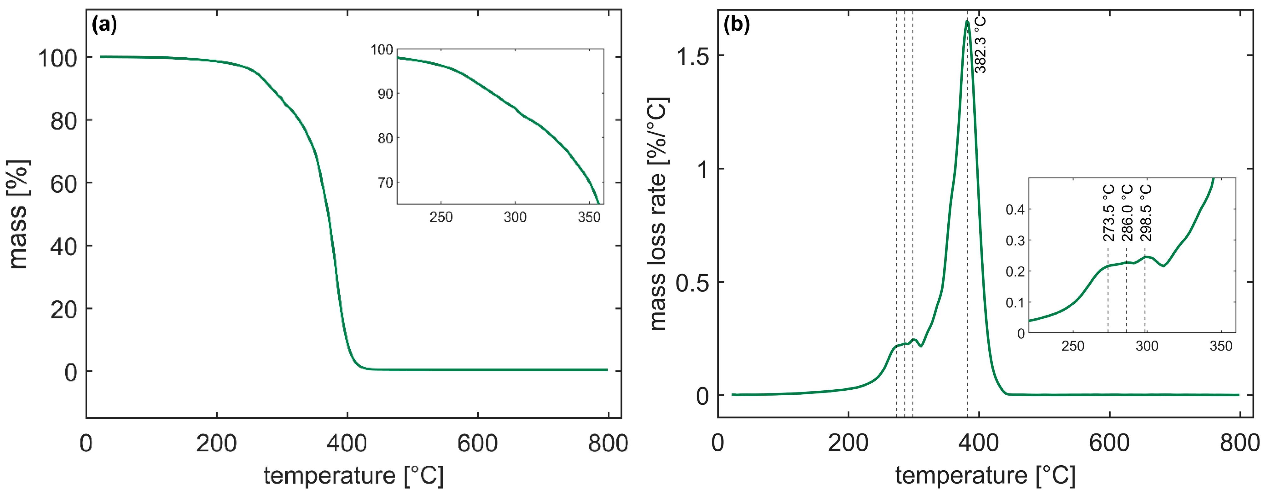
In the literature, the thermal degradation of PMMA was investigated, and several models were proposed and revised [46,47,48,49,50,51,52,53], also relying on combined techniques of TGA and FTIR analysis on the degradation products [54,55]. Generally, it is accepted that degradation of PMMA occurs in the following four steps: (i) radical transfer to the unsaturated chain end occurring at ~150 °C, (ii) scission of the chain at weak head-to-head bonds (~230 °C), (iii) radical transfer to unsaturated ends (~270 °C), and finally, (iv) random scission by fission of a methoxycarbonyl group within the main chain between 350 °C and 400 °C. Figure 7 depicts TGA results for E3. Maximum weight loss occurs at 382.3 °C, while it is possible to observe minor weight loss peaks at 273.5 °C, 286 °C, and 298.5 °C that can be attributed to the presence of smaller molecules existing in the sheet or to the rupture of weak head-to-head bonds in the main chain [56].
The DMA curves of E3 can be seen in Figure 8. The glass transition temperature is determined from the maximum loss factor ( tan δ ) and is equal to 92.6 °C. Previous studies [45,57,58] showed that the T g calculated based on tan δ can differ from the T g measured at the stepwise midpoint of the DSC thermogram and is generally higher in DMA graphs. A smaller peak, associated with secondary transitions such as β transitions or other chain mobility phenomena [41], or possibly related to the plasticizer media of the initiator, is observed at 65.6 °C. The presence of multiple peaks in the tan δ vs. temperature curve concurs with the hypothesis of imperfect polymerization due to the presence of plasticizer and possibly other additives in the initiator formula.

3.2. Woven and Non-Woven Fabric Composites

Woven composites were prepared using 10 layers of vCF woven fabric as reinforcement and Elium 158O with 3 wt.% Benzoclean LLV initiator as matrix, using VARIM technique, as explained in the Materials and Methods section. Assuming that no voids are present, the volume fraction of the fibers can be evaluated from the following rule of mixtures:
ρ c =   ρ f v f + ρ m 1 v f
where ρ c   is the composite density, ρ f   is the bulk fiber density, ρ m   is the bulk matrix density, and v f   is the fiber volume fraction. The densities were measured by weighing the materials on a scale in air and water. The measured values found were ρ c = 1.443 g c m 3 , ρ f = 1.824   g c m 3 , and ρ m = 1.213   g c m 3 . The non-woven fabric composites were prepared similarly to the woven counterpart. In this case, the measured density of the composite ( ρ c = 1.091 g c m 3 ) was less than that of the matrix, indicating the presence of a large amount of air pockets inside the material that are not considered in the measurement technique, leading to apparent lower values. Equation (1) can be modified to include the voids volume fraction, v v , obtaining:
ρ c =   ρ f v f + ρ m 1 v f v v
The fiber volume fraction can be easily estimated from the weight fraction, which in turn, is either evaluated knowing the thickness of the composite, the areal density of the fabric, and the number of layers, or it can be experimentally measured from the difference in mass before and after the resin burn-off procedure.
Once the fiber weight fraction is known, it can be converted to the fiber volume fraction, and the void volume fraction can then be evaluated using Equation (2). The volume fraction values are reported in Table 2. The large void content and the low fiber content in the case of the non-woven composite are confirmed. The low fiber content is caused by the enhanced stiffness in the z-direction and the porosity of the non-woven fabric; under the action of vacuum, the fabric is indeed compacted, but large pockets are still present to be filled by the matrix, resulting in a considerable amount of resin that is infused during the process. Concerning the presence of voids, it results from the combination of the viscosity of the resin, of the possible residual monomeric content, and of the architecture of the fabric, which results in a larger tortuosity during the impregnation phase.
Figure 9 shows the DMA curves of woven and non-woven composites. The glass transition temperature ( T g , tan δ   ) determined from the maximum loss factor ( tan δ ) was found equal to 101.3 and 106 °C for E3_CF and E3_NW, respectively. In the case of the woven composite, the height of the loss factor peak was found to be larger than that of the non-woven one. In the case of a strong interface between the matrix and the fibers, since the contribution to damping of carbon fibers can be neglected, the theoretical value of the loss factor of the composite should be proportional to that of the matrix, scaled by its volume fraction [59], therefore resulting in a smaller tan δ peak [60,61]. The DMA results in the present work showed a peak of tan δ   higher in the case of the composites with respect to that of the matrix, a result that also points in the direction of an active role of the interface or the void fraction in the dissipation of energy, thus confirming the weak interface. From the loss factor vs. temperature curves, it is also possible to observe that the value of the glass transition temperature, T g , tan δ   , is higher than that of the matrix, and that sub- T g secondary peaks are not present, an indication of the restriction imposed by the presence of the fibers on the mobility of the polymeric chains. Moreover, the polymer is only a fraction of the whole material that is tested; therefore, smaller peaks may be masked. DMA analysis results are summarized in Table 3, along with those of the matrix E3. The differences in the curves of the neat resin and those of the two composites (and possibly the small difference in T g , tan δ   between E3_CF and E3_NW) also underline the effect of the presence of the carbon fibers on the polymerization reaction; they determine different temperature profiles and capability to dissipate the heat produced by the exothermic reaction, due to the enhanced thermal conductivity of the carbon fibers [43]. This in turn leads to different reaction kinetics, which are strongly related to the final material properties [41,62].
The stress–strain curves from the flexural tests performed on the woven and non-woven composites are shown in Figure 10a, while histograms for the average values of flexural modulus, E f , flexural strength, σ f , and strain at flexural strength, ε f , are reported in Figure 10b and Figure 11. In the case of non-woven reinforcement, tests performed on specimens oriented perpendicularly with respect to the rolling direction showed generally higher modulus and strength but lower maximum strain. The anisotropy of the non-woven fabric composite is, therefore, confirmed, with results in agreement with the literature [15,63]. The increase in strength of E3_NW_R and E3_NW_T, with respect to the neat resin E3, is in the order of 40–45%, lower than in the case of the E3_CF composite. The reason for this must be found in the lower values of fiber volume fraction and the higher porosity found in the case of the composites prepared with non-woven fabrics.
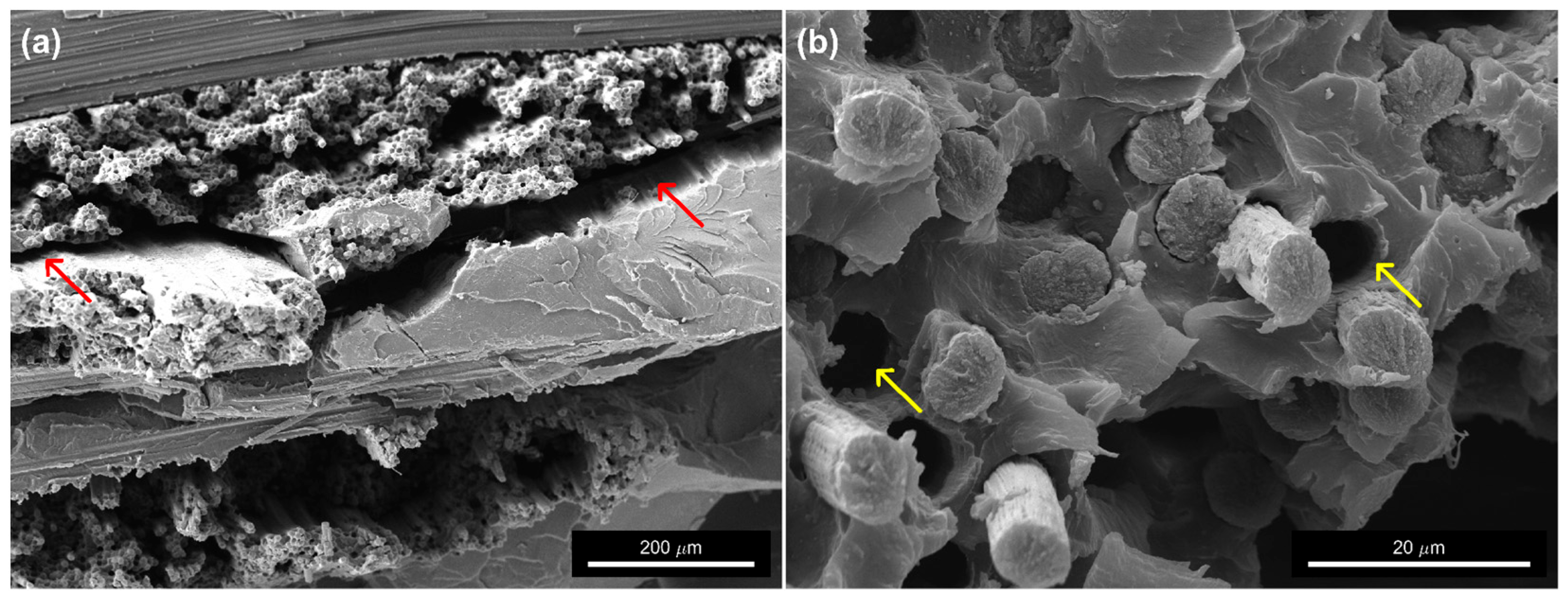
Table 4 shows a comparison of flexural tests from the present work with those reported in the literature. A normalization with respect to fiber volume fraction values was evaluated; although, more refined models should be adopted to reliably compare the properties. Khan et al. [64] investigated composites prepared with twill weave CF fabrics and Elium® 188 by vacuum-assisted resin transfer molding (VARTM). Fredi et al. [65] studied composites fabricated by hand lay-up followed by vacuum bagging with a plain weave CF fabric and Elium® 150. Budholia et al. [66] carried out an investigation on the flexural properties of Elium® 280 reinforced with thin non-crimp CF fabrics manufactured by resin transfer molding. Finally, Bandaru et al. [67] investigated composites fabricated with a plain weave CF fabric and Elium® 180 by VARIM. The results from the present work are comparable, in some cases slightly inferior, with those reported in literature. It should be considered that different grades of Elium® resin, other initiators, and reinforcements were used. In general, the poorer performance of the composite observed in some cases can be ascribed certainly to the lower fiber fraction obtained in the present work, possibly to the presence of voids, imperfect polymerization, and to some extent, to the weak interface between the matrix and carbon fibers. Indeed, from the fracture surfaces of woven fabric composites, shown in Figure 12, delamination and fiber pull-out are observed, thus indicating a low interfacial strength; similar results were found by Pini et al. [68,69] for unidirectional CF/Elium® composites prepared with infusion molding. Interestingly, if the properties are normalized with respect to the fiber volume fraction, the woven composite from the present work outperforms those from the selected literature works.
Concerning the non-woven fabric composites, critical points are the low fiber volume fraction and the evidence of bad impregnation and presence of voids, a result found by other authors [14,34]. The root cause is likely the infusion process set-up, particularly the vacuum source, which may not be powerful enough to ensure complete compaction of the reinforcement and proper filling of the spaces between the fibers (the vacuum pressure reached during infusion was ~0.8 bar). This is more perceivable in the case of the non-woven fabric because of the bending stiffness of the carbon fibers that must be overcome to compact the fabric and the large pores that must be squeezed [34]. Despite the issue encountered, some considerations on the results can still be made, as follows: the flexural properties, although inferior to those of the woven composite, are remarkable considering the low fiber volume fraction and the fact that the fabric is obtained from recycled CF. Indeed, the flexural strength and the flexural modulus, if normalized to v f , are in the range of those of the woven counterpart and the results from the literature (see Table 4). However, the performance of the material in the present form makes it suitable for semi-structural applications only, such as flooring and paneling in the building and automotive sectors, where lightweight properties and meeting recycling quotas are the aimed goals, even in the presence of mid-range mechanical performance. For example, underbody exterior panels in cars are an excellent application area for the present material.
The flexural tests showed a general better performance in the direction perpendicular to the rolling one. This anisotropic behavior is related to the architecture of the non-woven fabrics, which are known to sometimes exhibit different properties depending on the orientation relative to the rolling direction during production. Different preparations, parameters and fiber lengths strongly affect the anisotropy [70,71]. Unfortunately, in the present work, not all the details of the process are disclosed by the supplier of the non-woven fabric. However, its tensile properties were investigated in the two perpendicular directions R and T, as shown in Figure 13. Although in this case, it was difficult to measure the cross-sectional area to evaluate intrinsic properties, specimens having the same length and width were cut in the two directions, from the same fabric. It was found that in the transverse direction, the average maximum load was ~50% higher than in the rolling one, following the same trend as the results obtained for the relevant composite materials.
The fracture surfaces of the non-woven fabric composite tested in the rolling direction are shown in Figure 14a,b. The latter was selected as a clear example of a macroscopic void in the material; in the upper part of the image, the fracture surface is abruptly interrupted, revealing cave-like volume. The presence of this large void confirms the results reported in Table 2. Figure 14c,d show the fracture surfaces obtained from E3_NW_T samples. Although clean fibers, smooth fiber tracks, and fiber pull-out are also present in this case, the interfacial strength appears to be slightly higher than in the case of woven composite. Evidence of improved interfacial strength can be observed in Figure 14d; the fibers remained covered by the matrix, and the fracture occurred cohesively within the matrix rather than at the interface This finding could be explained by the rougher surface of the pyrolyzed fibers (evident in Figure 14c, in particular), which may enhance mechanical interlocking [72]. However, the different packing arrangements of the two types of composites lead to different stress states at the interface and, therefore, potentially to different failure modes as well. Moreover, while it can be asserted that no sizing is present in the non-woven fabric due to pyrolysis, no information is available regarding the woven fabric. Further confirmation on the strength of the interface comes from the DMA results; the height of the loss factor peak in the case of E3_NW is larger than that of the relevant matrix, E3, thus indicating less energy dissipated at the interface.

4. Conclusions and Future Perspectives

In recent years, a notable shift towards eco-friendly fiber-reinforced thermoplastics has emerged in response to growing environmental concerns, including waste generation and climate change. The recycling of carbon fibers from end-of-life composites has gained increasing attention as a strategy to promote sustainable development. This study explored the use of Elium® resin (Arkema) to manufacture fiber-reinforced thermoplastic composites reinforced with either woven virgin carbon fibers (vCF) or non-woven recycled carbon fibers (rCF). Key findings are as follows:
  • Optimal mechanical performance of the resin was achieved with 3 wt.% initiator concentration. Post-curing at 80 °C reduced performance, likely due to the specific composition of the initiator system.
  • Woven vCF composites demonstrated mechanical properties comparable to values reported in the literature, despite a lower fiber volume fraction, suggesting that further optimization of the resin infusion process and fiber–matrix interfacial adhesion could enhance performance.
  • Non-woven rCF composites exhibited approximately 20% of the mechanical performance of their virgin counterparts. Despite the reduced properties, the use of rCF presents a promising route for the development of sustainable composite materials. While their mechanical performance limits their adoption to semi-structural applications, the environmental benefit—through carbon fiber recycling—along with the cost-effectiveness and scalability of the processing technique make them highly attractive. These features are particularly relevant to the automotive industry, which has shown strong interest in lightweight, sustainable solutions for flooring, paneling, and interior components. Moreover, further reduction in porosity through thermal treatments is feasible due to the thermoplastic nature of the resin.
Future work will focus on hybrid non-woven mats combining recycled glass and carbon fibers and on improving impregnation using lower-viscosity Elium® resins.

Author Contributions

Conceptualization, S.T.T. and B.C.; methodology, S.T.T. and T.P.; validation, S.T.T., T.P., and M.S.; data curation, T.P.; writing—original draft preparation, S.T.T., T.P., and M.S.; writing—review and editing, S.T.T., T.P., M.S., I.B., F.S., J.T., and M.V.; supervision, F.S., J.T., and M.V. All authors have read and agreed to the published version of the manuscript.

Funding

This research received no external funding.

Acknowledgments

Financed by the European Union-NextGenerationEU (National Sustainable Mobility Center CN00000023, Italian Ministry of University and Research Decree n. 1033-17/06/2022, Spoke 11-Innovative Materials & Lightweighting). The opinions expressed are those of the authors only and should not be considered as representative of the European Union or the European Commission’s official position. Neither the European Union nor the European Commission can be held responsible for them. The authors would like to thank Arkema company for supplying the resin and Luciano Fattore and Riccardo Martufi from Fab Lab SAPeri&Co for the preparation of the specimens.

Conflicts of Interest

The authors declare no conflicts of interest.

References

  1. De, B.; Bera, M.; Bhattacharjee, D.; Ray, B.C.; Mukherjee, S. A Comprehensive Review on Fiber-Reinforced Polymer Composites: Raw Materials to Applications, Recycling, and Waste Management. Prog. Mater. Sci. 2024, 146, 101326. [Google Scholar] [CrossRef]
  2. Tayebi, S.T.; Sambucci, M.; Valente, M. Waste Management of Wind Turbine Blades: A Comprehensive Review on Available Recycling Technologies with A Focus on Overcoming Potential Environmental Hazards Caused by Microplastic Production. Sustainability 2024, 16, 4517. [Google Scholar] [CrossRef]
  3. Mishnaevsky, L. Sustainable End-of-Life Management of Wind Turbine Blades: Overview of Current and Coming Solutions. Materials 2021, 14, 1124. [Google Scholar] [CrossRef] [PubMed]
  4. Butenegro, J.A.; Bahrami, M.; Abenojar, J.; Martínez, M.Á. Recent Progress in Carbon Fiber Reinforced Polymers Recycling: A Review of Recycling Methods and Reuse of Carbon Fibers. Materials 2021, 14, 6401. [Google Scholar] [CrossRef]
  5. Bel Haj Frej, H.; Léger, R.; Perrin, D.; Ienny, P.; Gérard, P.; Devaux, J.-F. Recovery and Reuse of Carbon Fibre and Acrylic Resin from Thermoplastic Composites Used in Marine Application. Resour. Conserv. Recycl. 2021, 173, 105705. [Google Scholar] [CrossRef]
  6. Cousins, D.S.; Suzuki, Y.; Murray, R.E.; Samaniuk, J.R.; Stebner, A.P. Recycling Glass Fiber Thermoplastic Composites from Wind Turbine Blades. J. Clean. Prod. 2019, 209, 1252–1263. [Google Scholar] [CrossRef]
  7. Meyer zu Reckendorf, I.; Sahki, A.; Perrin, D.; Lacoste, C.; Bergeret, A.; Ohayon, A.; Morand, K. Chemical Recycling of Vacuum-Infused Thermoplastic Acrylate-Based Composites Reinforced by Basalt Fabrics. Polymers 2022, 14, 1083. [Google Scholar] [CrossRef] [PubMed]
  8. Pimenta, S.; Pinho, S.T. The Effect of Recycling on the Mechanical Response of Carbon Fibres and Their Composites. Compos. Struct. 2012, 94, 3669–3684. [Google Scholar] [CrossRef]
  9. Aravindan, P.; Becagli, F.; Longana, M.L.; Blok, L.G.; Pozegic, T.R.; Huntley, S.J.; Rendall, T.; Hamerton, I. Remanufacturing of Woven Carbon Fibre Fabric Production Waste into High Performance Aligned Discontinuous Fibre Composites. J. Compos. Sci. 2020, 4, 68. [Google Scholar] [CrossRef]
  10. Paulsen, E.B.; Enevoldsen, P. A Multidisciplinary Review of Recycling Methods for End-of-Life Wind Turbine Blades. Energies 2021, 14, 4247. [Google Scholar] [CrossRef]
  11. Job, S.; Leeke, G.; Mativenga, P.; Oliveux, G.; Pickering, S.; Shuaib, N. Composites Recycling—Where Are We Now? Composites UK. 2016. Available online: https://compositesuk.co.uk/wp-content/uploads/2021/10/Recycling-Report-2016-Light-Background.pdf (accessed on 14 August 2025).
  12. Yang, Y.; Boom, R.; Irion, B.; van Heerden, D.-J.; Kuiper, P.; de Wit, H. Recycling of Composite Materials. Chem. Eng. Process. Process Intensif. 2012, 51, 53–68. [Google Scholar] [CrossRef]
  13. Pakdel, E.; Kashi, S.; Varley, R.; Wang, X. Recent Progress in Recycling Carbon Fibre Reinforced Composites and Dry Carbon Fibre Wastes. Resour. Conserv. Recycl. 2021, 166, 105340. [Google Scholar] [CrossRef]
  14. Tse, B.; Yu, X.; Gong, H.; Soutis, C. Flexural Properties of Wet-Laid Hybrid Nonwoven Recycled Carbon and Flax Fibre Composites in Poly-Lactic Acid Matrix. Aerospace 2018, 5, 120. [Google Scholar] [CrossRef]
  15. Barnett, P.R.; Ghossein, H.K. A Review of Recent Developments in Composites Made of Recycled Carbon Fiber Textiles. Textiles 2021, 1, 433–465. [Google Scholar] [CrossRef]
  16. Raghvendra, K.; Sravanthi, L. Fabrication Techniques of Micro/Nano Fibres Based Nonwoven Composites: A Review. Mod. Chem. Appl. 2017, 05, 1–11. [Google Scholar] [CrossRef]
  17. Yilmaz, K.B.; Sabuncuoglu, B.; Yildirim, B.; Silberschmidt, V.V. A Brief Review on the Mechanical Behavior of Nonwoven Fabrics. J. Eng. Fibers Fabr. 2020, 15, 1558925020970197. [Google Scholar] [CrossRef]
  18. Patnaik, P.K.; Swain, P.T.R.; Mishra, S.K.; Purohit, A.; Biswas, S. Recent Developments on Characterization of Needle-Punched Nonwoven Fabric Reinforced Polymer Composites—A Review. Mater. Today Proc. 2020, 26, 466–470. [Google Scholar] [CrossRef]
  19. Devine, M.; Bajpai, A.; Ó Brádaigh, C.M.; Ray, D. ‘Resin Welding’: A Novel Route to Joining Acrylic Composite Components at Room Temperature. Compos. Part B Eng. 2024, 272, 111212. [Google Scholar] [CrossRef]
  20. Sacchetti, F.; Grouve, W.J.B.; Warnet, L.L.; Villegas, I.F. Effect of Resin-Rich Bond Line Thickness and Fibre Migration on the Toughness of Unidirectional Carbon/PEEK Joints. Compos. Part Appl. Sci. Manuf. 2018, 109, 197–206. [Google Scholar] [CrossRef]
  21. Stavrov, D.; Bersee, H.E.N. Resistance Welding of Thermoplastic Composites-an Overview. Compos. Part Appl. Sci. Manuf. 2005, 36, 39–54. [Google Scholar] [CrossRef]
  22. Bernet, N.; Michaud, V.; Bourban, P.-E.; Månson, J.-A.E. Commingled Yarn Composites for Rapid Processing of Complex Shapes. Compos. Part Appl. Sci. Manuf. 2001, 32, 1613–1626. [Google Scholar] [CrossRef]
  23. Mitschang, P.; Blinzler, M.; Wöginger, A. Processing Technologies for Continuous Fibre Reinforced Thermoplastics with Novel Polymer Blends. Compos. Sci. Technol. 2003, 63, 2099–2110. [Google Scholar] [CrossRef]
  24. Qiao, Y.; Fring, L.D.; Pallaka, M.R.; Simmons, K.L. A Review of the Fabrication Methods and Mechanical Behavior of Continuous Thermoplastic Polymer Fiber–Thermoplastic Polymer Matrix Composites. Polym. Compos. 2023, 44, 694–733. [Google Scholar] [CrossRef]
  25. Bodaghi, M.; Park, C.H.; Krawczak, P. Reactive Processing of Acrylic-Based Thermoplastic Composites: A Mini-Review. Front. Mater. 2022, 9, 931338. [Google Scholar] [CrossRef]
  26. van Rijswijk, K.; Bersee, H.E.N. Reactive Processing of Textile Fiber-Reinforced Thermoplastic Composites—An Overview. Compos. Part Appl. Sci. Manuf. 2007, 38, 666–681. [Google Scholar] [CrossRef]
  27. Qin, Y.; Summerscales, J.; Graham-Jones, J.; Meng, M.; Pemberton, R. Monomer Selection for In Situ Polymerization Infusion Manufacture of Natural-Fiber Reinforced Thermoplastic-Matrix Marine Composites. Polymers 2020, 12, 2928. [Google Scholar] [CrossRef]
  28. Valente, M.; Rossitti, I.; Biblioteca, I.; Sambucci, M. Thermoplastic Composite Materials Approach for More Circular Components: From Monomer to In Situ Polymerization, a Review. J. Compos. Sci. 2022, 6, 132. [Google Scholar] [CrossRef]
  29. Bhudolia, S.K.; Perrotey, P.; Joshi, S.C. Optimizing Polymer Infusion Process for Thin Ply Textile Composites with Novel Matrix System. Materials 2017, 10, 293. [Google Scholar] [CrossRef] [PubMed]
  30. Obande, W.; Ó Brádaigh, C.M.; Ray, D. Continuous Fibre-Reinforced Thermoplastic Acrylic-Matrix Composites Prepared by Liquid Resin Infusion—A Review. Compos. Part B Eng. 2021, 215, 108771. [Google Scholar] [CrossRef]
  31. Tian, L.; Zhang, P.; Xian, G. Continuous Fiber Reinforced Thermoplastic Composite Pultrusion with in Situ Polymerizable Methyl Methacrylate: A Review. Polym. Compos. 2023, 44, 4345–4369. [Google Scholar] [CrossRef]
  32. Shen, Y.; Du, W.; Sui, X.; Liu, X.; Tang, B.Z.; Yang, J. Green Manufacturing Process Design for Infusible Acrylic Resin Composites: A Data-Guided Life Cycle Management Model Incorporating Material-Process-Property-Energy-Emission Relationships. Compos. Part Appl. Sci. Manuf. 2024, 181, 108146. [Google Scholar] [CrossRef]
  33. Feraboli, P.; Kawakami, H.; Wade, B.; Gasco, F.; DeOto, L.; Masini, A. Recyclability and Reutilization of Carbon Fiber Fabric/Epoxy Composites. J. Compos. Mater. 2012, 46, 1459–1473. [Google Scholar] [CrossRef]
  34. Shah, D.U.; Schubel, P.J. On Recycled Carbon Fibre Composites Manufactured through a Liquid Composite Moulding Process. J. Reinf. Plast. Compos. 2016, 35, 533–540. [Google Scholar] [CrossRef]
  35. Cider|Circular Product Design for Automotive Components Made from Recycled and Sustainable Composite Material. Available online: https://www.igcv.fraunhofer.de/en/research/reference_projects/sustainable_circular_product_design_composites_cider.html (accessed on 14 August 2025).
  36. Elium® 158 O TDS. Available online: http://www.arkema.com (accessed on 14 August 2025).
  37. Benzoclean 40 LLV TDS. Available online: https://www.rsm-web.com/wp-content/uploads/2018/10/TDS-BENZOCLEAN-40-LLV-Rev.-1.0-05_2016-ENG.pdf (accessed on 14 August 2025).
  38. ASTM D790-17; Standard Test Methods for Flexural Properties of Unreinforced and Reinforced Plastics and Electrical Insulating Materials. ASTM International: West Conshohocken, PA, USA, 2017.
  39. ASTM D4065-20; Standard Practice for Plastics: Dynamic Mechanical Properties: Determination and Report of Procedures. ASTM International: West Conshohocken, PA, USA, 2020.
  40. ASTM D3171-22; Standard Test Methods for Constituent Content of Composite Materials. ASTM International: West Conshohocken, PA, USA, 2022.
  41. Raponi, O.d.A.; Barbosa, L.C.M.; de Souza, B.R.; Ancelotti Junior, A.C. Study of the Influence of Initiator Content in the Polymerization Reaction of a Thermoplastic Liquid Resin for Advanced Composite Manufacturing. Adv. Polym. Technol. 2018, 37, 3579–3587. [Google Scholar] [CrossRef]
  42. de Andrade Raponi, O.; Righetti de Souza, B.; Miranda Barbosa, L.C.; Ancelotti Junior, A.C. Thermal, Rheological, and Dielectric Analyses of the Polymerization Reaction of a Liquid Thermoplastic Resin for Infusion Manufacturing of Composite Materials. Polym. Test. 2018, 71, 32–37. [Google Scholar] [CrossRef]
  43. Charlier, Q.; Fontanier, J.-C.; Lortie, F.; Pascault, J.-P.; Gerard, J.-F. Rheokinetic Study of Acrylic Reactive Mixtures Dedicated to Fast Processing of Fiber-Reinforced Thermoplastic Composites. J. Appl. Polym. Sci. 2019, 136, 47391. [Google Scholar] [CrossRef]
  44. O’neil, G.A.; Wisnudel, M.B.; Torkelson, J.M. Gel Effect in Free Radical Polymerization: Model Discrimination of Its Cause. AIChE J. 1998, 44, 1226–1231. [Google Scholar] [CrossRef]
  45. Hutchinson, J.M. Determination of the Glass Transition Temperature: Methods Correlation and Structural Heterogeneity. J. Therm. Anal. Calorim. 2009, 98, 579–589. [Google Scholar] [CrossRef]
  46. Kashiwagi, T.; Inaba, A.; Brown, J.E.; Hatada, K.; Kitayama, T.; Masuda, E. Effects of Weak Linkages on the Thermal and Oxidative Degradation of Poly(Methyl Methacrylates). Macromolecules 1986, 19, 2160–2168. [Google Scholar] [CrossRef]
  47. Manring, L.E. Thermal Degradation of Saturated Poly(Methyl Methacrylate). Macromolecules 1988, 21, 528–530. [Google Scholar] [CrossRef]
  48. Manring, L.E. Thermal Degradation of Poly(Methyl Methacrylate). 2. Vinyl-Terminated Polymer. Macromolecules 1989, 22, 2673–2677. [Google Scholar] [CrossRef]
  49. Manring, L.E.; Sogah, D.Y.; Cohen, G.M. Thermal Degradation of Poly(Methyl Methacrylate). 3. Polymer with Head-to-Head Linkages. Macromolecules 1989, 22, 4652–4654. [Google Scholar] [CrossRef]
  50. Manring, L.E. Thermal Degradation of Poly(Methyl Methacrylate). 4. Random Side-Group Scission. Macromolecules 1991, 24, 3304–3309. [Google Scholar] [CrossRef]
  51. Holland, B.J.; Hay, J.N. The Effect of Polymerisation Conditions on the Kinetics and Mechanisms of Thermal Degradation of PMMA. Polym. Degrad. Stab. 2002, 77, 435–439. [Google Scholar] [CrossRef]
  52. Gao, Z.; Kaneko, T.; Hou, D.; Nakada, M. Kinetics of Thermal Degradation of Poly(Methyl Methacrylate) Studied with the Assistance of the Fractional Conversion at the Maximum Reaction Rate. Polym. Degrad. Stab. 2004, 84, 399–403. [Google Scholar] [CrossRef]
  53. Galgano, A.; Branca, C.; Di Blasi, C.; Vollaro, P.; Milella, E. Modeling the Ignition of Poly(Methyl Methacrylate)/Carbon Nanotube Nanocomposites. Polym. Degrad. Stab. 2017, 144, 344–353. [Google Scholar] [CrossRef]
  54. Saladino, M.L.; Motaung, T.E.; Luyt, A.S.; Spinella, A.; Nasillo, G.; Caponetti, E. The Effect of Silica Nanoparticles on the Morphology, Mechanical Properties and Thermal Degradation Kinetics of PMMA. Polym. Degrad. Stab. 2012, 97, 452–459. [Google Scholar] [CrossRef]
  55. Gałka, P.; Kowalonek, J.; Kaczmarek, H. Thermogravimetric Analysis of Thermal Stability of Poly(Methyl Methacrylate) Films Modified with Photoinitiators. J. Therm. Anal. Calorim. 2014, 115, 1387–1394. [Google Scholar] [CrossRef]
  56. Porras, J.; Morales, M.A.; Hernandez, C.; Maranon, A.; Michaud, V.; Porras, A. Development of a Sustainable Thermoplastic Composite Material Using Manicaria Saccifera Fabric and Elium® Resin. J. Nat. Fibers 2025, 22, 2462977. [Google Scholar] [CrossRef]
  57. Rieger, J. The Glass Transition Temperature Tg of Polymers—Comparison of the Values from Differential Thermal Analysis (DTA, DSC) and Dynamic Mechanical Measurements (Torsion Pendulum). Polym. Test. 2001, 20, 199–204. [Google Scholar] [CrossRef]
  58. Ehrenstein, G.W.; Riedel, G.; Trawiel, P. Dynamic Mechanical Analysis (DMA). In Thermal Analysis of Plastics; Carl Hanser Verlag GmbH & Co. KG: Munich, Germany, 2004; pp. 236–299. [Google Scholar]
  59. Dong, S.; Gauvin, R. Application of Dynamic Mechanical Analysis for the Study of the Interfacial Region in Carbon Fiber/Epoxy Composite Materials. Polym. Compos. 1993, 14, 414–420. [Google Scholar] [CrossRef]
  60. Bhudolia, S.K.; Perrotey, P.; Joshi, S.C. Enhanced Vibration Damping and Dynamic Mechanical Characteristics of Composites with Novel Pseudo-Thermoset Matrix System. Compos. Struct. 2017, 179, 502–513. [Google Scholar] [CrossRef]
  61. Fredi, G.; Dorigato, A.; Pegoretti, A. Dynamic-Mechanical Response of Carbon Fiber Laminates with a Reactive Thermoplastic Resin Containing Phase Change Microcapsules. Mech. Time-Depend. Mater. 2020, 24, 395–418. [Google Scholar] [CrossRef]
  62. Palmieri, B.; Petriccione, A.; De Tommaso, G.; Giordano, M.; Martone, A. An Efficient Thermal Cure Profile for Thick Parts Made by Reactive Processing of Acrylic Thermoplastic Composites. J. Compos. Sci. 2021, 5, 229. [Google Scholar] [CrossRef]
  63. Genna, S.; Papa, I.; Trovalusci, F. Mechanical Behavior of Recycled Carbon Fiber Epoxy and Vinylester Composites Produced by Resin Infusion with Flexible Tooling Technology (RIFT). J. Compos. Mater. 2023, 57, 4025–4033. [Google Scholar] [CrossRef]
  64. Khan, T.; Ali, M.A.; Irfan, M.S.; Cantwell, W.J.; Rehan, U. Visualizing Pseudo-Ductility in Carbon/Glass Fiber Hybrid Composites Manufactured Using Infusible Thermoplastic Elium® Resin. Polym. Compos. 2023, 44, 1859–1876. [Google Scholar] [CrossRef]
  65. Fredi, G.; Dorigato, A.; Pegoretti, A. Novel Reactive Thermoplastic Resin as a Matrix for Laminates Containing Phase Change Microcapsules. Polym. Compos. 2019, 40, 3711–3724. [Google Scholar] [CrossRef]
  66. Bhudolia, S.K.; Joshi, S.C.; Bert, A.; Yi Di, B.; Makam, R.; Gohel, G. Flexural Characteristics of Novel Carbon Methylmethacrylate Composites. Compos. Commun. 2019, 13, 129–133. [Google Scholar] [CrossRef]
  67. Bandaru, A.K.; Pothnis, J.R.; Portela, A.; Gujjala, R.; Ma, H.; O’Higgins, R.M. Flexural and Interlaminar Shear Response of Novel Methylmethacrylate Composites Reinforced with High-Performance Fibres. Polym. Test. 2024, 140, 108578. [Google Scholar] [CrossRef]
  68. Pini, T.; Caimmi, F.; Briatico-Vangosa, F.; Frassine, R.; Rink, M. Fracture Initiation and Propagation in Unidirectional CF Composites Based on Thermoplastic Acrylic Resins. Eng. Fract. Mech. 2017, 184, 51–58. [Google Scholar] [CrossRef]
  69. Pini, T.; Briatico-Vangosa, F.; Frassine, R.; Rink, M. Matrix Toughness Transfer and Fibre Bridging Laws in Acrylic Resin Based CF Composites. Eng. Fract. Mech. 2018, 203, 115–125. [Google Scholar] [CrossRef]
  70. Kang, T.J.; Lee, S.H. Characterization of Reinforcing Web Structures in Needle Punched Nonwoven Composites. J. Compos. Mater. 1999, 33, 2116–2132. [Google Scholar] [CrossRef]
  71. Manis, F.; Stegschuster, G.; Wölling, J.; Schlichter, S. Influences on Textile and Mechanical Properties of Recycled Carbon Fiber Nonwovens Produced by Carding. J. Compos. Sci. 2021, 5, 209. [Google Scholar] [CrossRef]
  72. Smoleń, J.; Olesik, P.; Jała, J.; Adamcio, A.; Kurtyka, K.; Godzierz, M.; Kozera, R.; Kozioł, M.; Boczkowska, A. The Use of Carbon Fibers Recovered by Pyrolysis from End-of-Life Wind Turbine Blades in Epoxy-Based Composite Panels. Polymers 2022, 14, 2925. [Google Scholar] [CrossRef] [PubMed]
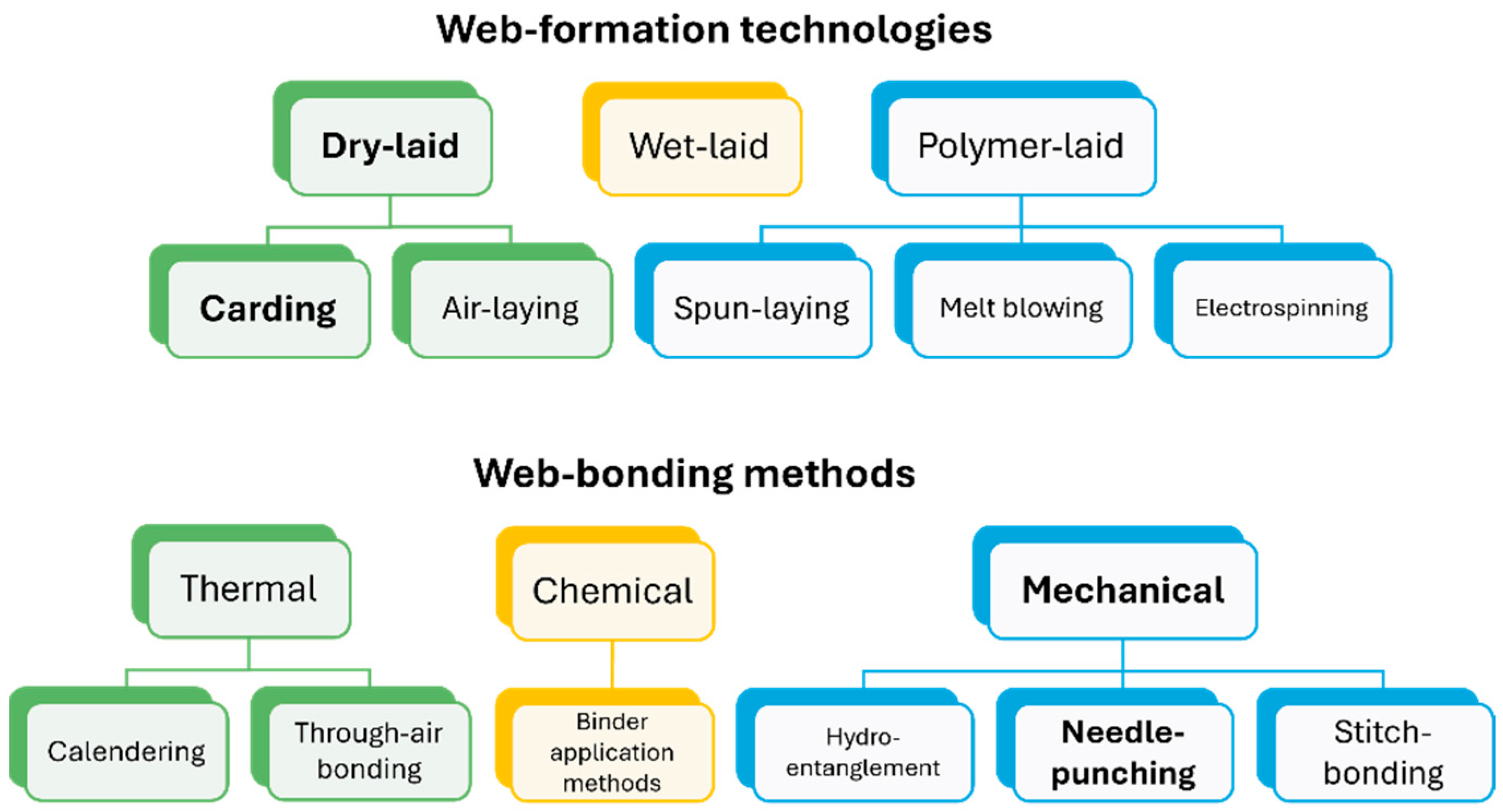
Figure 1. Non-woven fabric preparation routes. The technologies and the methods adopted in the present work are indicated by bold text.
Jcs 09 00441 g001
Figure 2. Non-woven fabric roll.
Jcs 09 00441 g002
Figure 3. Schematic of vacuum-assisted resin infusion system.
Jcs 09 00441 g003
Figure 4. Representative flexural stress vs. strain curves of neat resin formulations (a) and average values of flexural modulus of the neat resin formulations (b).
Jcs 09 00441 g004
Figure 5. Average values of flexural strength (a) and strain at flexural strength (b) of the neat resin formulations.
Jcs 09 00441 g005
Figure 6. DSC thermogram of E3. Solid line represents heat flow for the 2nd heating ramp. Dashed lines indicate the linear fits in the glassy and rubbery states. Triangle marks the glass transition temperature, Tg.
Jcs 09 00441 g006
Figure 7. TGA curves of E3. Residual mass vs. temperature (a) and DTG curves (b).
Jcs 09 00441 g007
Figure 8. DMA curves of E3: storage modulus vs. temperature (a) and loss factor vs. temperature (b).
Jcs 09 00441 g008
Figure 9. DMA curves of E3_CF and E3_NW: storage modulus vs. temperature (a) and loss factor vs. temperature (b).
Jcs 09 00441 g009
Figure 10. Representative flexural stress vs. strain curves of woven and non-woven fabric composites (a) and average flexural modulus of woven and non-woven fabric composites (b).
Jcs 09 00441 g010
Figure 11. Average flexural strength (a) and strain at flexural strength (b) of woven and non-woven fabric composites.
Jcs 09 00441 g011
Figure 12. SEM micrographs of the fracture surface of woven fabric composite E3_CF after flexural tests at different magnifications. Yellow and red arrows highlight fiber pull-out and delamination, respectively.
Jcs 09 00441 g012
Figure 13. Load–strain curves of the tensile tests on the dry non-woven fabrics in the two perpendicular directions R and T.
Jcs 09 00441 g013
Figure 14. SEM micrographs of the fracture surface of non-woven fabric composite after flexural tests at different magnifications: (a,b) E3_NW_R and (c,d) E3_NW_T. Yellow, green, and white arrows highlight fiber pull-out, fiber surface roughness, and cohesive fracture, respectively.
Jcs 09 00441 g014
Table 1. Labeling and composition of the samples.
LabelBPO Content [wt.%]Reinforcement TypePost-Curing
E22--
E33--
E44--
E3_PC3-2 h at 80 °C
E3_CF310 plies of CF fabric (160 g/m2)-
E3_NW33 plies of non-woven CF fabric (200 g/m2)-
Table 2. Fiber, matrix, and void volume fractions measured from the areal density and with resin burn-off method.
LabelMethod v f [%] v m [%] v v [%]
E3_CFFabric areal density42.854.62.6
E3_NWFabric areal density11.372.915.8
Resin burn-off14.171.814.1
Table 3. Summary of the properties of the materials investigated with DMA.
Label T g , t a n δ [°C] t a n δ [-]
E392.60.32
E3_CF101.30.85
E3_NW_R106.00.49
Table 4. Comparison of the flexural properties of E3_CF and E3_NW with data from the literature.
SourceElium® Grade v f [-] σ f [MPa] E f [GPa] σ f / v f [MPa] E f / v f [GPa]
E3_CF158O0.4361836144484
E3_NW_T158O0.14113879957
E3_NW_R158O0.14107676443
Khan et al. [64]188O0.776585085665
Fredi et al. [65]1500.574693882767
Budholia et al. [66]2800.5881351139588
Bandaru et al. [67]1800.544654086975
Disclaimer/Publisher’s Note: The statements, opinions and data contained in all publications are solely those of the individual author(s) and contributor(s) and not of MDPI and/or the editor(s). MDPI and/or the editor(s) disclaim responsibility for any injury to people or property resulting from any ideas, methods, instructions or products referred to in the content.