1. Introduction
Carbon fiber (CF) has become an essential material in several industries, including aerospace, defense, automotive, and wind energy, primarily due to its exceptional strength, stiffness, and low density. Its widespread use actively contributes to reducing greenhouse gas emissions by reducing the weight of structures. Global CF production doubled from 27,000 tons to 54,000 tons between 2009 and 2014 and was expected to exceed 150,000 tons in 2022 [
1].
With an expected annual growth of around 6%, especially in the e-mobility and renewables sectors, waste from manufacturing (so-called off-cuts, prepregs) and end-of-life (EOL) products is predicted to increase. It is estimated that up to 20,000 tons of such waste could be generated annually by 2025. This problem is particularly relevant in the aerospace industry, where aircraft structures such as the Boeing 787 and Airbus A350 contain up to 50% CFRP. Around 12,000 aircraft are expected to end their service life by 2045 [
2].
The existing methods of managing composite waste, such as incineration and landfilling, are environmentally and economically unsustainable. Therefore, increasing attention is being paid to recycling methods that can preserve the material value of carbon fibers.
All recycling methods are significantly less energy-intensive than primary fiber production. All recycling methods have their own specifics, requirements for the technological process, input material, and ensured quality of outputs. Burning fibers in furnaces without a protective atmosphere is possible, and the results achieved appear promising both in terms of the quality of the recycled fibers and in terms of the complexity of the implemented process [
3].
Mechanical recycling, which consists of crushing and grinding the material into fractions of different sizes, is one of the recycling technologies used. The result is a mixture of fibers and matrix, where the fibers often reach a length of 2–20 mm. The advantages are low investment cost and simplicity of the method, but the disadvantages are the degradation of fiber properties and the formation of matrix residues. This method often serves as a preparatory step for more advanced processes [
4,
5,
6,
7].
According to earlier studies, waste from aeronautical processes represents up to 30 to 40% of the weight of the CFRP material used. The production of a modern aircraft generates approximately several dozen tons of composite waste (cutting, drilling, non-standard shaping). Among this waste, drilling and machining can represent several tons of carbon waste. This waste is hazardous to health and harmful to the environment if not properly captured, filtered, and recycled [
8].
Thermal recycling—pyrolysis—occurs in an inert atmosphere at 400–700 °C. The organic component decomposes into gaseous and liquid products, while the carbon fibers remain intact, often with carbonized residues. The mechanical properties of recycled fibers can reach 80–90% of the original values. In the case of using two-stage pyrolysis with oxidation, this can lead to up to 95% strength retention. An alternative to pyrolysis is the so-called fluidized bed, which ensures effective heating and mechanical separation of fibers with a fast process and high fiber purity [
9,
10]. Fine particles resulting from machining have a high surface-area-to-volume ratio, which makes them easy to burn. The resulting very short carbon fibers are often carbonized and require further treatment, e.g., chemical cleaning. Chemical methods allow for cleaner carbon fragments (microfibers or agglomerates) used as conductive additives, pigments, or fillers in electrical engineering and construction to be obtained. Sometimes, this fine waste is used for energy purposes; for example, by incineration in cement plants, where energy from polymer components is used. Recycled carbon fibers (rCFs) represent a valuable secondary raw material. Their use is limited by their shortened length (50 μm to several mm), possible damage, and the absence of the original surface treatment. However, rCFs retain 70–90% of their original mechanical strength [
11,
12,
13,
14].
Chemical recycling is less economically and environmentally advantageous. The decomposition of the polymer matrix is carried out using solvents (e.g., benzyl alcohol, HNO
3, ethanol) or supercritical media such as supercritical water or alcohol, which offer a more environmentally friendly approach. This method can retain the original mechanical properties of the fibers (up to 98%), but high operating costs and technological complexity limit its industrial application [
15,
16,
17,
18].
Electrochemical recycling uses high-voltage electrical pulses to destroy the matrix, creating pure carbon fibers with minimal damage and up to 90% strength retention. However, it is energy-intensive (2.6× more than mechanical recycling) [
19].
Microwave recycling is a variant of pyrolysis that uses electromagnetic waves for faster heating. Carbonized compounds reduce the quality of the output, and the mechanical properties of recycled fibers reach approximately 80% of their original values [
5,
16,
17].
Waste chips and dust from CFRP machining (drilling, milling, grinding, cutting) represent a specific recycling problem. They are very fine, heterogeneous, often contaminated, and have a significantly shortened residual fiber length, which makes their reuse difficult. However, there are ways to recycle or utilize this waste. Machining waste is mainly in fine chips (1–3 mm) and dust, where the carbon fibers are significantly shortened, and the mixture contains remnants of the polymer matrix and abrasive particles. Research has shown that short fibers from shredded CFRP can be used in injection molded parts with a 30–40% improvement in mechanical properties compared to fully polymer systems [
20,
21,
22].
Pyrolysis can achieve tensile strengths of up to around 3.5 GPa and an elastic modulus of 200–230 GPa. rCFs are an attractive alternative to virgin fibers, with a price of up to 70% lower and a carbon footprint reduction of up to 80% [
23].
The application of rCFs is wide, e.g., in the automotive industry (BMW i3, ELG Carbon Fibre Ltd., Bilston, UK) [
20], construction (concrete reinforcement), aviation sector (Airbus A220), sports equipment, 3D printing, and electrical engineering [
13,
24,
25].
Industrial scrap and carbon fiber polymer composite (CFRP) waste have been successfully recycled into new composite products to be reused in high-value applications [
10,
25]. It has been shown that the chemical pretreatment of fibers and the hybridization approach can further improve the performance properties of prepared composites [
11].
This study focuses on pyrolysis in the air of CFRP machining chips—by-products of drilling processes. These fine chips pose specific challenges due to their high surface-to-volume ratio, heterogeneous morphology, and susceptibility to oxidation. We aim to (i) quantify mass loss across thermal gradients, (ii) evaluate the structural integrity of carbon fibers, and (iii) assess the feasibility and environmental impact of fiber recovery without a protective atmosphere.
This study investigates the changes that occurs in carbon fibers exposed to high temperatures in an oxidizing atmosphere. It uses a clean combustion method, unlike recycling methods, only temperature, and no other environments that could affect the process and hence the properties of the fibers.
The results support the circular economy objectives by providing an accessible and low-cost route to partial CFRP recycling and informing safety protocols in high-risk applications [
12,
26,
27,
28,
29,
30,
31].
Recycled carbon fibers can be used in application areas where high mechanical strength is not required but rather where lower cost, weight savings, and environmental impact are priorities. The cost of recycling depends on the method used (e.g., pyrolysis, solvolysis) and the amount and quality of the input material [
32].
This work also constitutes a significant contribution to other works that have addressed the question of the behavior of composite systems during combustion and provides new information on the destruction of fibers in an oxidizing atmosphere at temperatures that are not tested in the case of standard recycling processes.
The results of the present study support the circular economy objectives by providing an accessible and low-cost route to CFRP recycling and informing safety protocols in high-risk applications [
33].
2. Materials and Methods
2.1. Materials
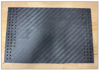
This study used two types of epoxy-based CFRP specimens: a commercial-grade tubular structure (Compo Tech PLUS, spol. s.r.o., Sušice, Czech Republic) and a laboratory-fabricated flat panel (Technical University of Liberec, Liberec, Czech Republic). The material parameters are summarized in
Table 1.
2.2. Machining and Chip Collection
Drilling was performed using a DMG MORI CMX 600V vertical machining center. Two 5 mm carbide drill bits (PRECITOOL, Neuenstein, Czech Republic; types 102620 and 102632) were selected, representing uncoated and coated tools. The cutting speed was fixed at 120 min−1. Fine chips generated during drilling were collected using a POC9 M1 vacuum extraction unit (CONRAD, Hirschau, Germany) with a 99% efficiency for particles > 0.3 µm. A custom 3D-printed flange equipped with PEGATEX ANTISTAT nonwoven textile (Němec Trade, s.r.o., Bučovice, Czech Republic; 17 g/m2) was employed to capture ultrafine debris.
2.3. Oxidation Process Protocol
Heat treatment of the CFRP chips was carried out using a high-temperature furnace in an air environment (VEB ELEKTRO, Berlin, Germany). The oxidation process was conducted in unglazed porcelain crucibles (temperature-resistant up to 1350 °C). Samples were subjected to target temperatures of 200 °C, 300 °C, 400 °C, 500 °C, 600 °C, 700 °C, and 800 °C. For each temperature, five specimens were processed. The mass before and after pyrolysis was measured using a KERN KB 120-3 analytical balance (KERN & Sohn, Balingen, Germany; accuracy 0.001 g). The surface temperature was monitored via a non-contact IR thermometer (AR872D, National Scientific Corp., Beijing, China).
2.4. Microscopic Characterization
SEM imaging was performed using a TESCAN MIRA 3 scanning electron microscope (TESCAN GROUP, Czech Republic). Both an overview and detailed images were acquired to assess the fiber surface integrity, diameter, and signs of degradation (e.g., pitting, fragmentation, formation of hollow structures). Special attention was paid to identifying the morphological changes associated with increasing temperature and air exposure.
2.5. Data Analysis
Weight loss values were statistically evaluated and plotted against temperature. SEM images were qualitatively assessed to identify the onset and progression of fiber degradation. A comparative analysis of the two composite sources (tube vs. plate) and the two tool types was conducted to examine the material- and process-dependent effects.
3. Results
This work aimed to determine the weight loss of chip samples from two different composite systems (plate and tube) reinforced with carbon fibers during combustion without the use of a protective atmosphere, i.e., during combustion in air, and at the same time to assess the state of degradation of the carbon fibers in the pre-selected temperature ranges. Combustion without a protective atmosphere was deliberately chosen for two reasons: The first reason was whether this method is applicable in common technical practice when the investment in a furnace with a protective atmosphere is higher and, at the same time, whether a protective atmosphere is necessary. The second reason was whether carbon fibers in the burned sample behave in pyrolysis in the air like in pyrolysis conducted under a protective atmosphere. The combustion of carbon fibers in the air is also a problem that can occur in traffic accidents and the subsequent burning of cars and aircraft that use carbon fiber-reinforced composite materials as structural components.
It has been reported that carbon fibers do not undergo degradation at a temperature of 800 °C and that the structure of the fibers remains largely unchanged. The pyrolysis of carbon composites in an inert atmosphere is a classic step for the recycling of CFRP. In an oxidizing environment, the degradation of carbon fibers begins at about 550 °C, and it is significant already at 800 °C with a drastic drop in their resistance. However, conducted experiments have confirmed the possibilities of obtaining good results when recycling carbon fibers without a protective atmosphere [
25,
34].
Each chip sample was weighed before combustion and, after removal from the furnace, was left in the air to cool and weighed again. From the difference in weight, the weight loss of the material was calculated for each temperature interval from laboratory temperature to 200 °C/300/400 °C/500 °C/600 °C/700/800 °C. The experiment was repeated five times for each temperature interval, each sample, and each cutting tool. The sample was removed after reaching the predetermined temperature of the set temperature interval, and after cooling, it was subjected to microscopic analysis to assess the degradation of the resin, the condition of the carbon fiber surface, the diameter of the fibers, or their degradation.
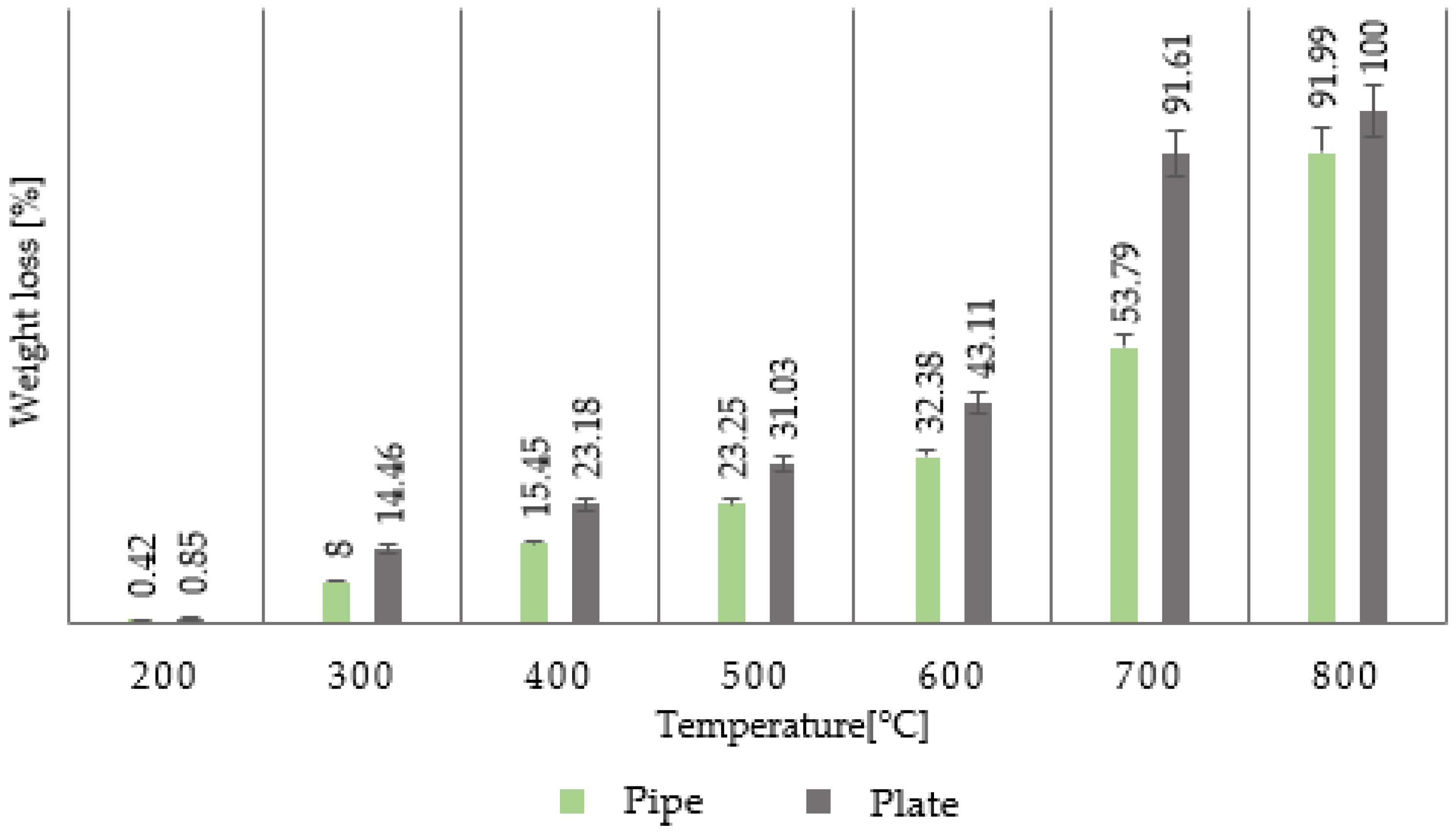
After pyrolysis, no further modifications were performed on the analyzed fibers. The results were purposefully divided according to the type of material from which the composite chip was taken and according to the cutting tools used. The graphs in
Figure 1 show the weight loss of the composite chip material depending on the temperature and the cutting tool/drill used. Samples of composite chips from the tube and plate intended for examining the weight loss during their combustion were taken using two types of drilling tools with the same diameter of 5 mm. The first was an uncoated tool with the designation 102620, while the second was a coated tool with the designation 102632. Drilling into the composite samples was carried out at a cutting speed of 120 min
−1.
The effect of the surface treatment of the tools used was negligible in the case of the plate, while in the case of the tube, the difference was in units of percent, probably due to different chip dimensions or fiber lengths. Shorter fibers will decompose more easily at high temperatures. The effect of the tool surface on the chip length was not addressed in this work.
3.1. Weight Loss of Composite Chips Generated During Tube Drilling
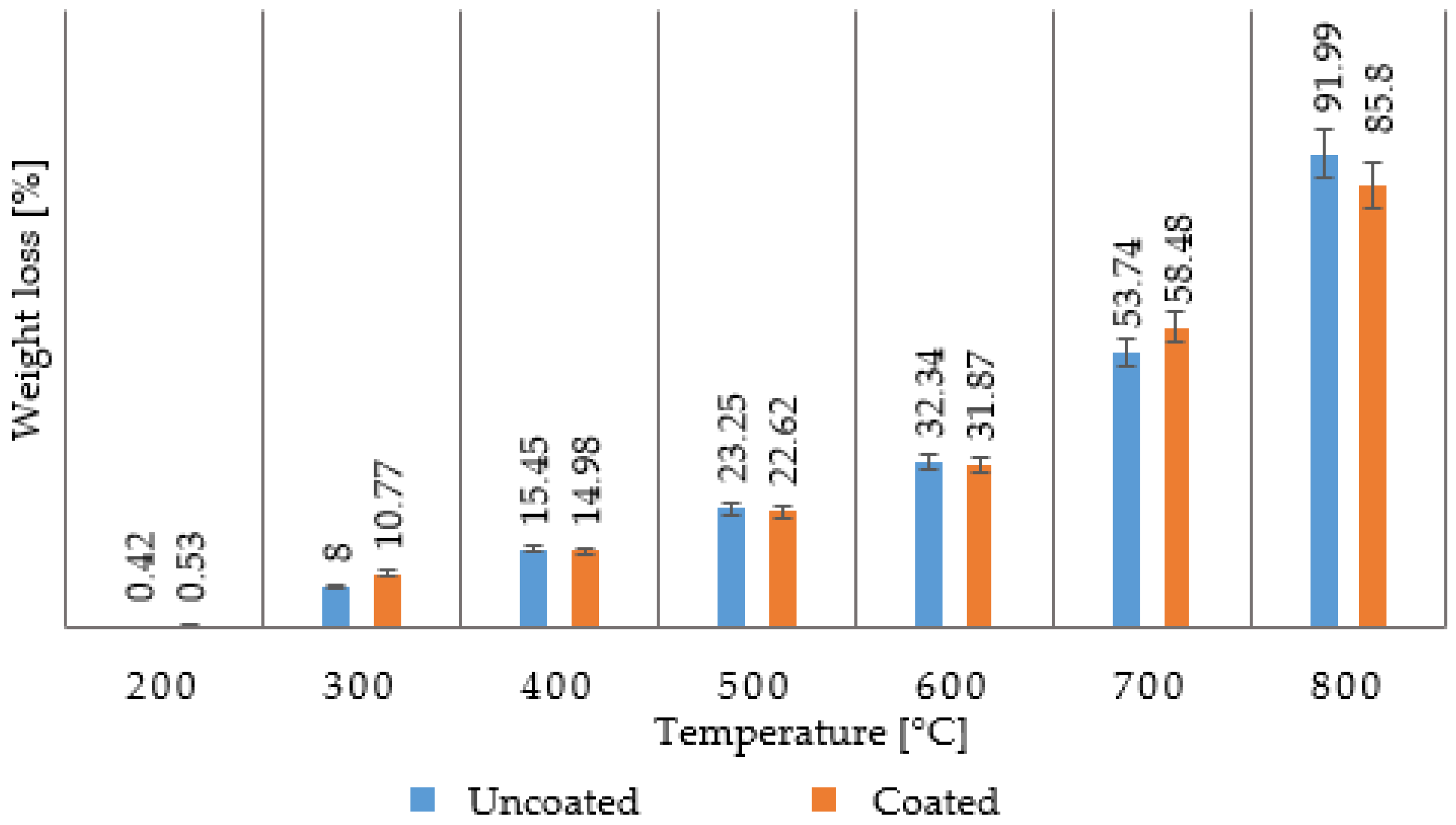
Figure 1 shows the weight loss of a composite chip formed from a tube at a cutting speed of v
c = 120 min
−1 for both drilling tools. It can be clearly stated that in the temperature range from laboratory temperature to 200 °C, there is practically no loss of the polymer matrix because the temperature is too low for the polymer to start undergoing thermal degradation. In the range of 200–300 °C, the weight loss is already noticeable, but only at the level of a few percent, which means that the decomposition of the polymer matrix is just beginning to occur. In the 300–400 °C range, the weight loss is already noticeable at the level of 15%, but it is not significant. In the interval of 400–500 °C, the weight loss is already noticeable at approximately 23%. This means that the epoxy resin is already degrading, burning, and forming combustion gases, releasing carbon fiber. In the interval of 500–600 °C, which is given in professional publications as the temperature interval for recycling, in which the resin’s degradation and the fiber’s release occurs, it is also possible to detect an increase in the weight loss of the material by another 10% in this case of combustion in the presence of air. This interval can be narrowed down to a narrower temperature range in which the resin is completely burned out. At the same time, there is no degradation of the carbon fibers or a reduction in their original diameter. The carbon fiber generally degrades at higher temperatures, its diameter decreases, and surface degradation occurs [
22,
26].
These degradations are limited when using a protective atmosphere, but these changes are noticeable when burning without it or in the air. In the interval of 600–700 °C, the weight loss increases by tens of percent. The same is true in the interval of 700–800 °C. Further measurements at higher temperatures were not performed for work safety, as structures similar to carbon nanotubes were microscopically analyzed. The graph in
Figure 1 shows that at a cutting speed of v
c = 120 min
−1 and when using two selected types of cutting tools, there are no fundamental differences in the weight loss of the composite chips that are burned up to a temperature of 600 °C. This difference is noticeable at temperatures of 700 °C and 800 °C, but it is only a matter of percentages, and this assessment is not of fundamental importance for further considerations.
3.2. Weight Loss of Composite Chips Generated During Plate Drilling
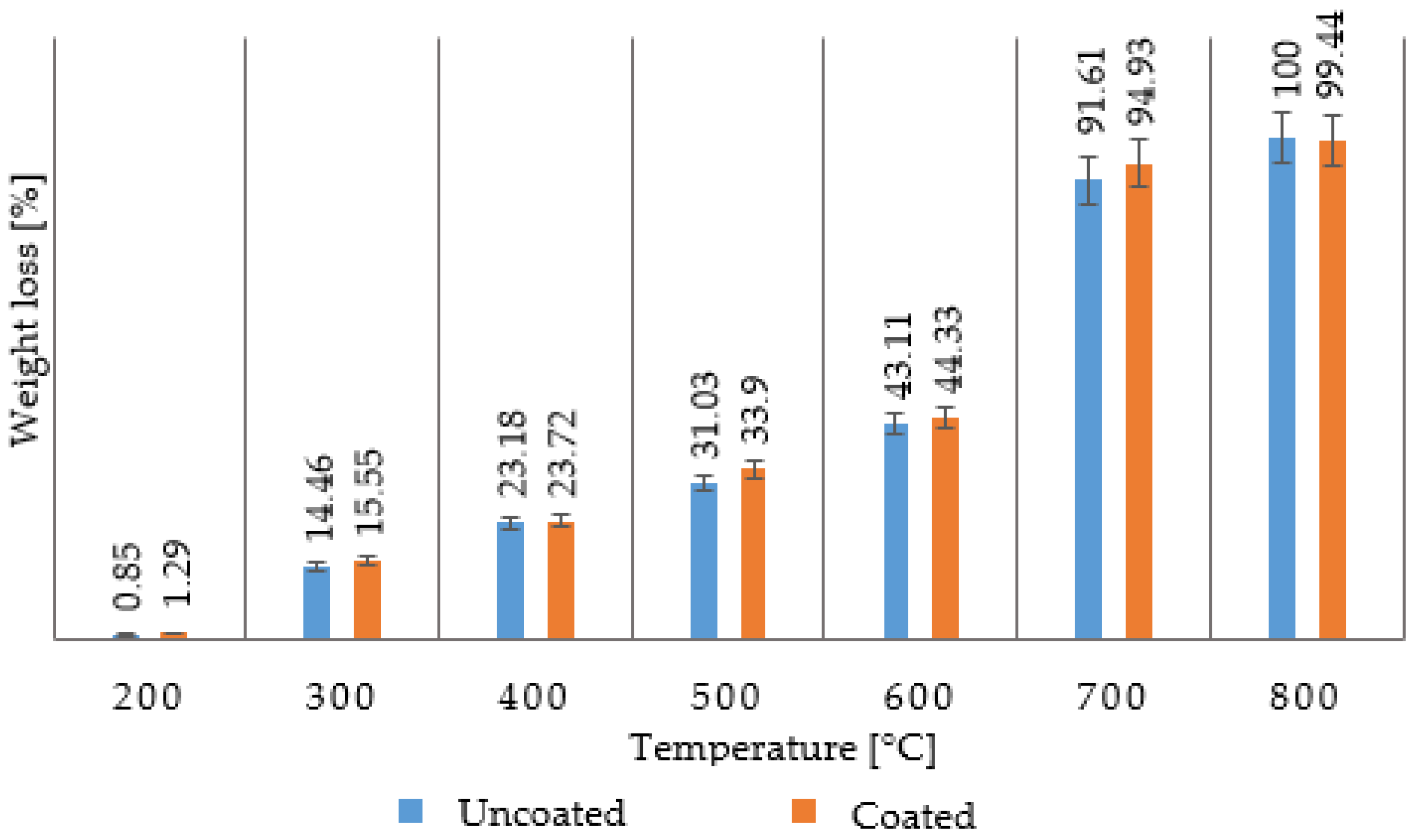
Figure 2 shows the weight loss of a composite chip formed from a plate at a cutting speed of v
c = 120 min
−1 for both cutting tools. It can be clearly stated that in the case of the temperature interval from laboratory temperature to 200 °C, there is practically no loss of the polymer matrix because the temperature is too low for the polymer to start thermally degrading. However, in this case, the weight loss is twice as much compared to drilling a tube. In the interval of 200–300 °C, the weight loss is already noticeable, which means that the decomposition of the polymer matrix begins to occur with greater intensity. In the interval of 300–400 °C, the weight loss is already noticeable at 23%, higher by about 7% than in the case of a tube. In the interval of 400–500 °C, the weight loss is already noticeable and is at more than 31%, which means that the epoxy resin is already degrading and burning. Decomposition by-products are formed, and the carbon fiber is released from the original polymer matrix. In the interval of 500–600 °C, which is given in professional publications as the temperature interval when recycling occurs, in which the resin degradation and fiber release occur, it is also possible to detect an increase in the weight loss of the material by another 11% to 12%. This temperature interval is an interval that, as in the previous case, can be narrowed down to a narrower temperature interval in which the resin is completely burned out and the degradation of the carbon fibers does not occur. At higher temperatures, the carbon fiber generally degrades, its diameter decreases, and surface degradation occurs, which is not desirable from the point of view of the further use of the fibers [
22,
25].
These degradations are limited when using a protective atmosphere, while the changes are noticeable when burning without or in the air. In the interval of 600–700 °C, the weight loss increases by up to 50%. All carbon fibers are burned at 700–800 °C. From the graph in
Figure 2, it is clear that at a cutting speed v
c = 120 min
−1 and when using two selected types of cutting tools, there are no fundamental differences in the weight loss of the burned composite chips.
3.3. Microscopic Evaluation of Carbon Fiber Degradation After Combustion of Composite Chips from Tube and Plate
Fiber analysis using a scanning electron microscope was performed for an uncoated tool (designation 102620), commonly used in machining composite systems, at a cutting speed of vc = 120 min−1. The chips obtained from machining both materials under investigation—tubes and plates—were used for the analysis. The image analysis describes an overview and detailed images to capture changes in the chip sample during thermal treatment. For the recycling process to be successful, the polymer matrix, here epoxy resin, must be removed. At the same time, there must be no degradation of the surface of the carbon fibers, a reduction in their diameter, or other changes that would negatively affect the further use of these recycled fibers.
3.3.1. Microscopic Evaluation of Carbon Fiber Degradation After Combustion of Composite Chips from a Tube
The electron microscope images in
Figure 3 show carbon fibers both individually and in clusters where the fibers are bonded with epoxy resin. When drilling composite systems, both fragments consisting of polymer and fibers are formed, and the fibers released from this fragment are independent. The released fibers have different lengths and different fracture patterns. The fracture is usually perpendicular to the fiber or at an angle of 45° to 60°. Short fibers are formed by crushing the material when the cutting tool passes through the blank wall. The images in
Figure 3 show fibers that have undergone combustion at temperatures of 200 °C and 300 °C. No significant changes are visible here, corresponding to the results obtained in measuring the mass losses after combustion.
The electron microscope images in
Figure 4 show carbon fibers burned at 400 °C and 500 °C. When burned in the range of 400 °C and 500 °C, residues of epoxy resin adhering to the carbon fibers are visible, shown on the right of
Figure 4. The surface of the carbon fibers is more or less clean. The image shows small particles and fragments of carbon fibers that were crushed during the sample drilling as the tool passed through the hole.
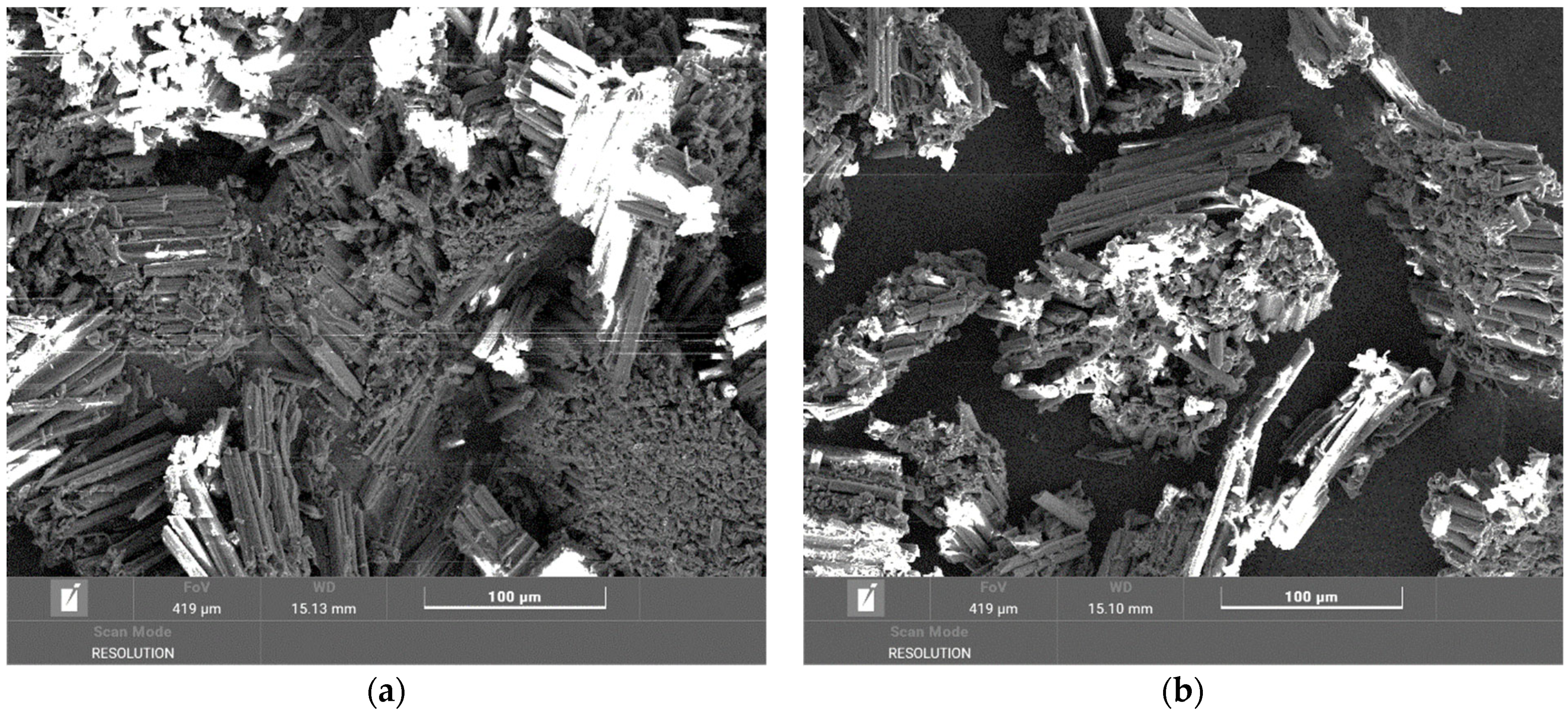
The electron microscope images in
Figure 5 show carbon fibers burned at 600 °C. The surface of the carbon fibers is clean. The image shows small particles, which are fragments of carbon fibers. In the image in
Figure 5 on the right, a fracture of the carbon fiber with a characteristic internal morphology is visible.
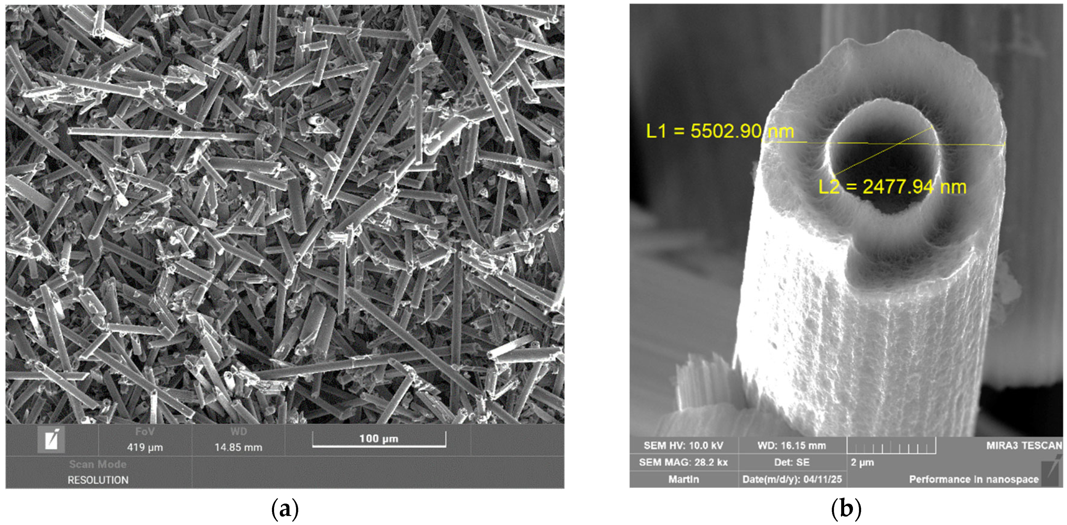
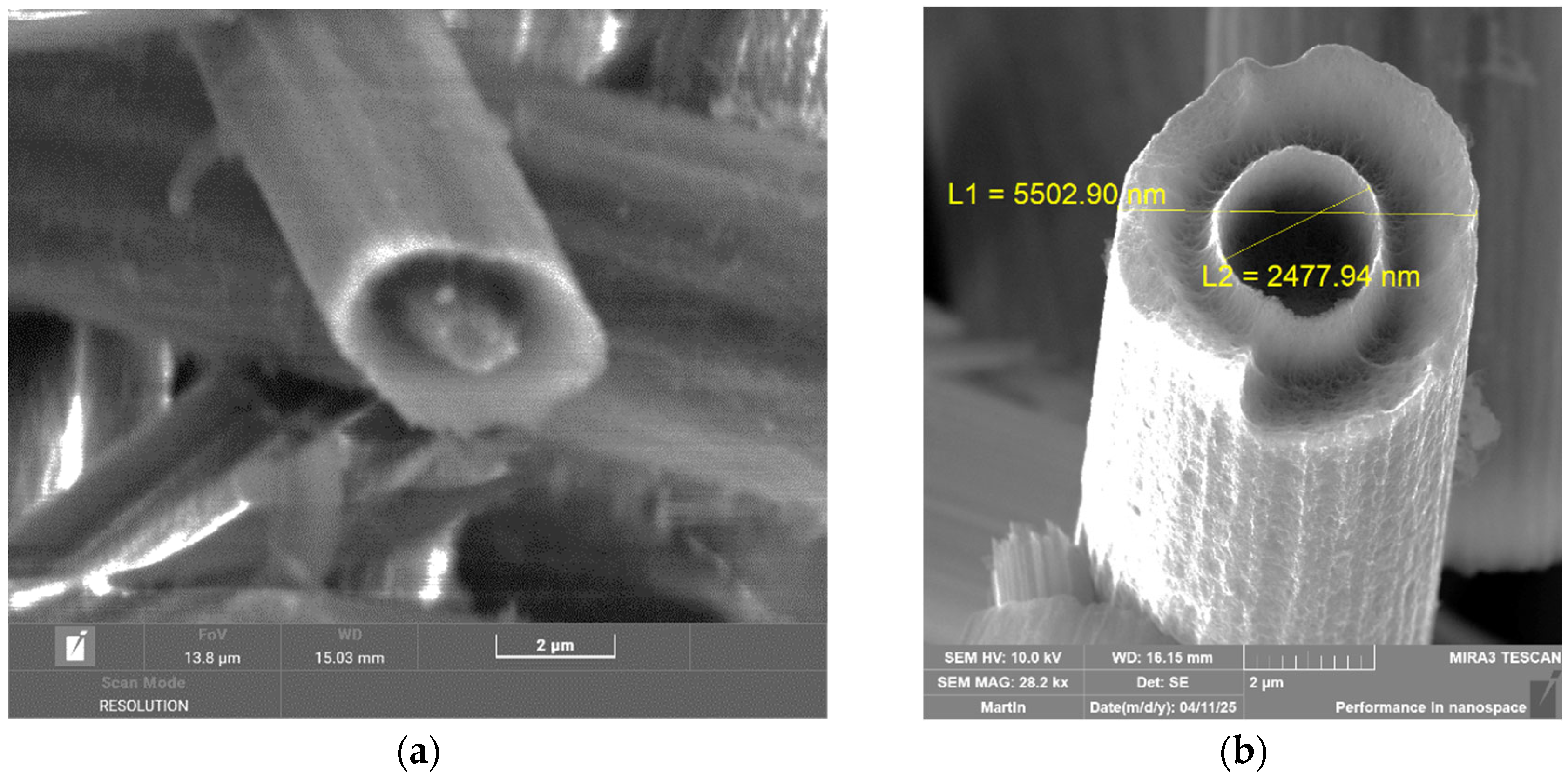
The electron microscope images in
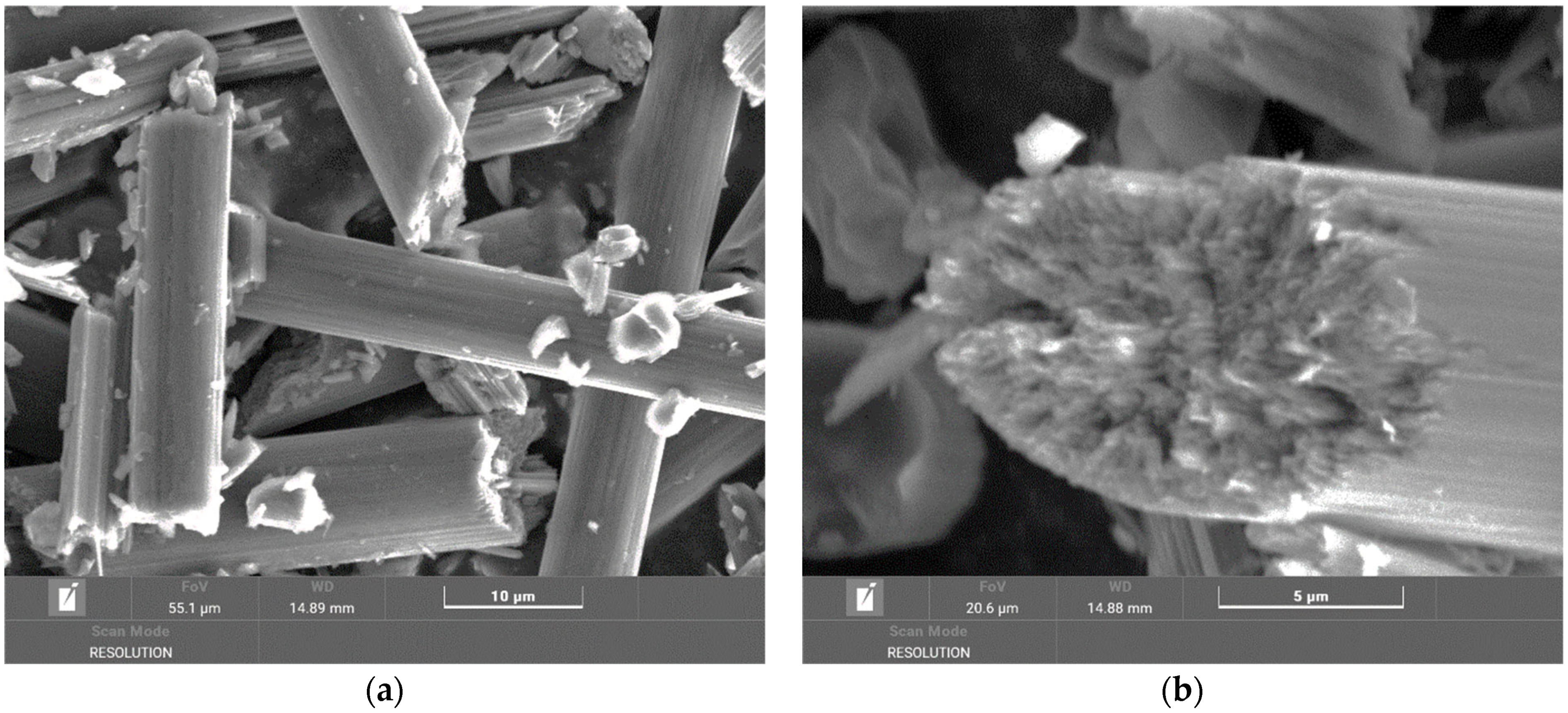
Figure 6 show carbon fibers burned at 700 °C. The surface of the carbon fibers is clean, without resin residues. The fibers have different lengths, and a large part of them shows surface defects and the formation of a cavity inside. The image in
Figure 6 on the right clearly shows the cavity and its diameter and a simultaneous reduction in the fiber diameter. The fiber surface is not smooth, which indicates the degradation processes to which the fibers were exposed. These degradation changes are probably related to the oxidation–reduction processes occurring at these temperatures in the presence of degrading epoxy resin and interaction with its decomposition products. The formation of cavities inside the fibers is probably related to the morphology of the given carbon fiber or, instead, to the production technology.
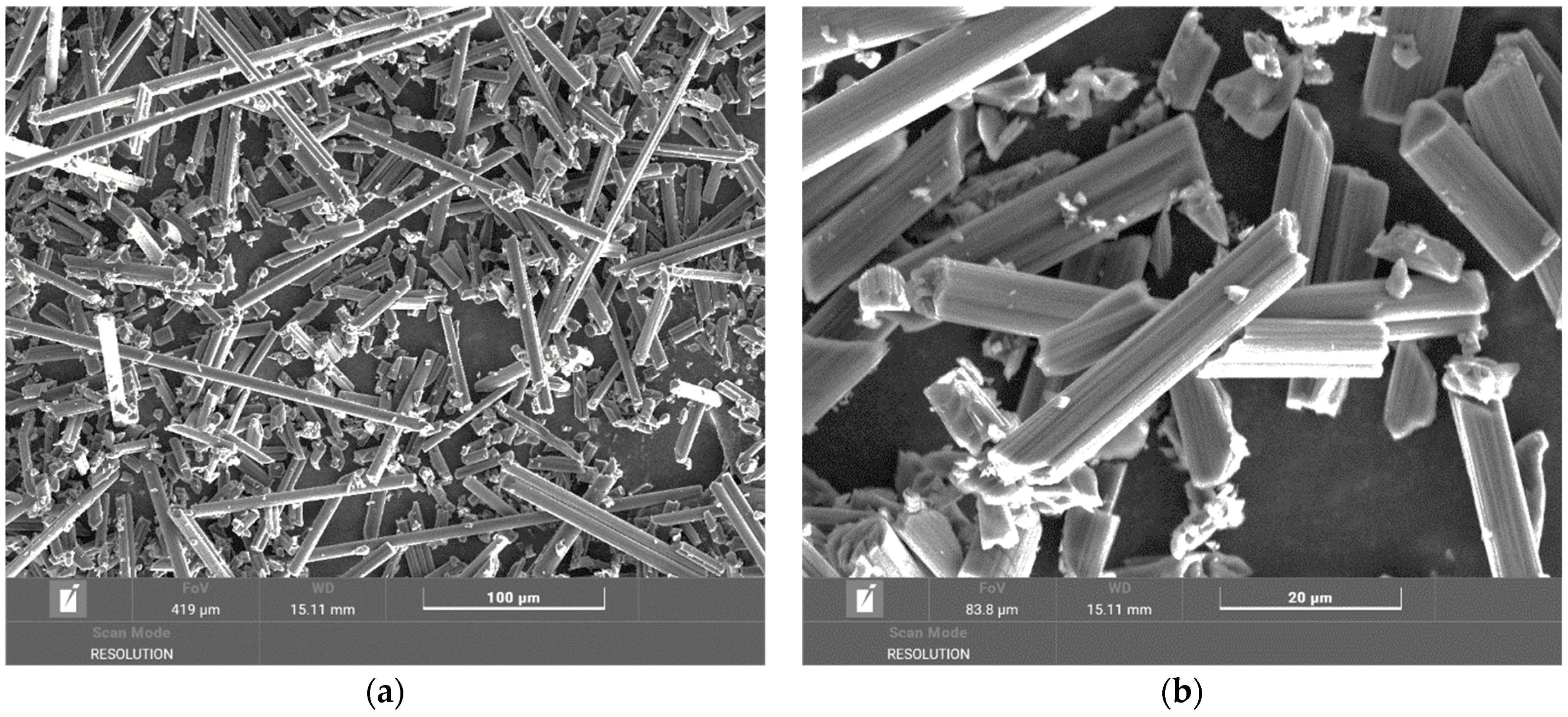
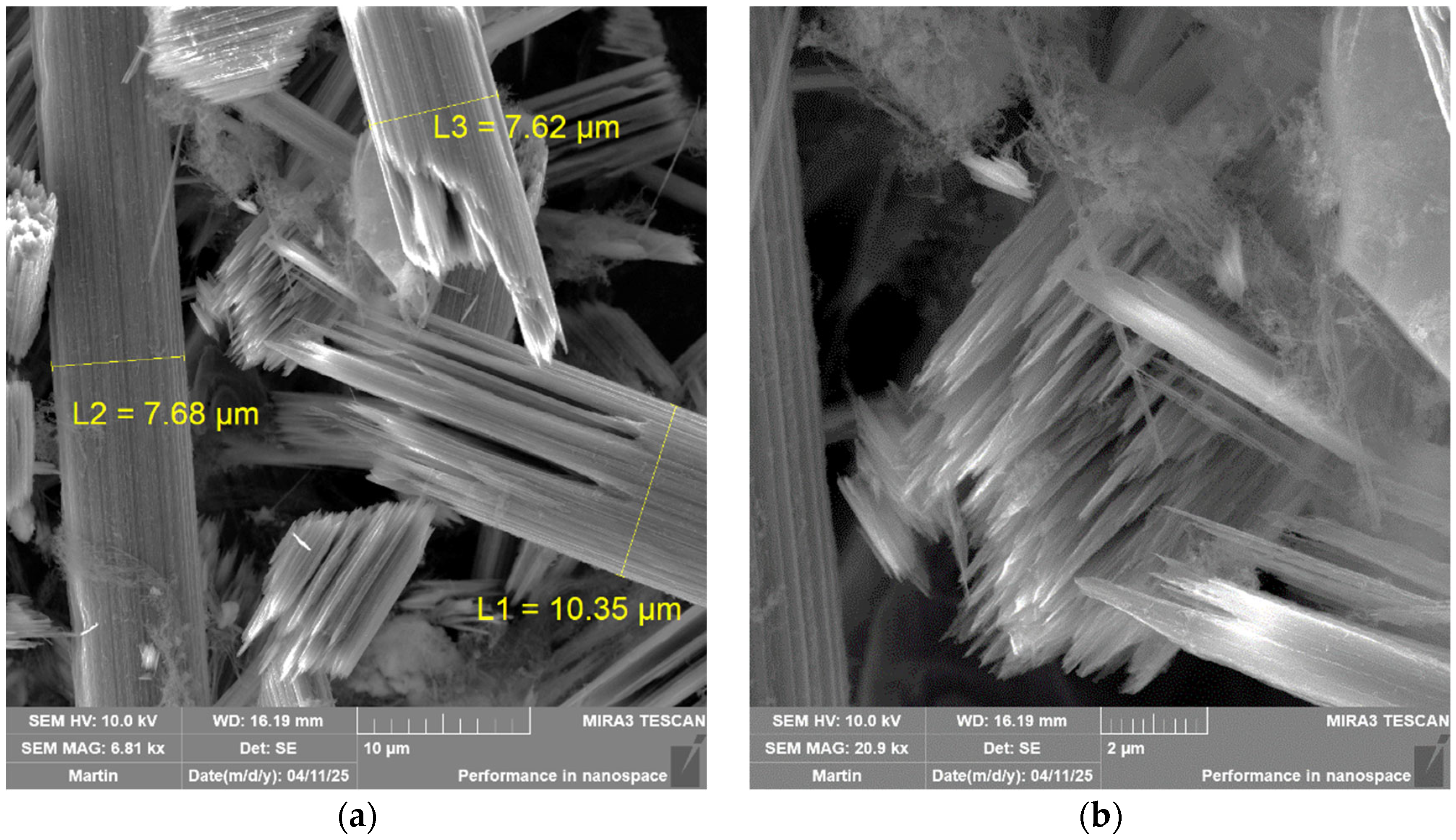
The electron microscope images in
Figure 7 show carbon fibers burned at 800 °C. The surface of the carbon fibers is clean, without resin residues. The fibers have a completely different surface character; it is evident that they break up into finer needle-like fragments with a thickness/diameter in submicrometer/nanometer dimensions. The length of the resulting fragments is in the tens of micrometers. There are no visible cavities, which could have been a transitional state during the degradation of the carbon fibers at a lower temperature.
The electron microscope images in
Figure 7 show larger carbon fibers than the original fibers. This is probably caused by the release of the internal structure of the fiber at high temperatures and in the presence of oxygen, as a result of which sharp needle-like structures are then released. It is clear from the images that the dimensions of these structures can reach hundreds of nanometers. The detailed image in
Figure 7 on the right shows very fine structures, which may be nanostructures resulting from burning, i.e., decomposition, or structures that, on the contrary, arise as a result of decomposition and use the decomposed material as a building material to form fibrous fine structures. In any case, the decomposition of carbon fibers at high temperatures in the presence of air leads to the formation of structures that are very dangerous to health and the environment.
3.3.2. Microscopic Evaluation of Carbon Fiber Degradation After Combustion of Composite Chips from the Plate
When drilling composite systems, larger or smaller fragments consisting of polymer and fibers are created, as well as fibers that are released from this fragment and are independent. These fibers and fragments are visible in the electron microscope images in
Figure 8. From the weight loss measurements, it is clear that at temperatures of 200 °C and 300 °C, there is no significant loss of the epoxy matrix.
At combustion temperatures of 400 °C and 500 °C, resin losses are already noticeable. The fibers are loosened and shed the resin stuck to their surface. As can be seen from these images, the lengths of the fibers are different, from hundreds of micrometers to tens of micrometers (
Figure 9). The diameters of the fibers were not changed, so it can be stated that at these temperatures, there is no degradation of the fibers.
There is an increased weight loss in the temperature range of up to 600 °C compared to the sample from the tube and the temperature range of up to 500 °C. As can be seen from the images in
Figure 10, the fibers are clean on the surface, without any polymer matrix residues. From the overview image, it is clear that the fiber lengths range from hundreds to tens of micrometers. At this temperature, when all the matrix is removed, it is also possible to identify carbon fiber fragments at the level of units of micrometers, which are created by chipping and breaking off from carbon fibers during drilling [
27,
28].
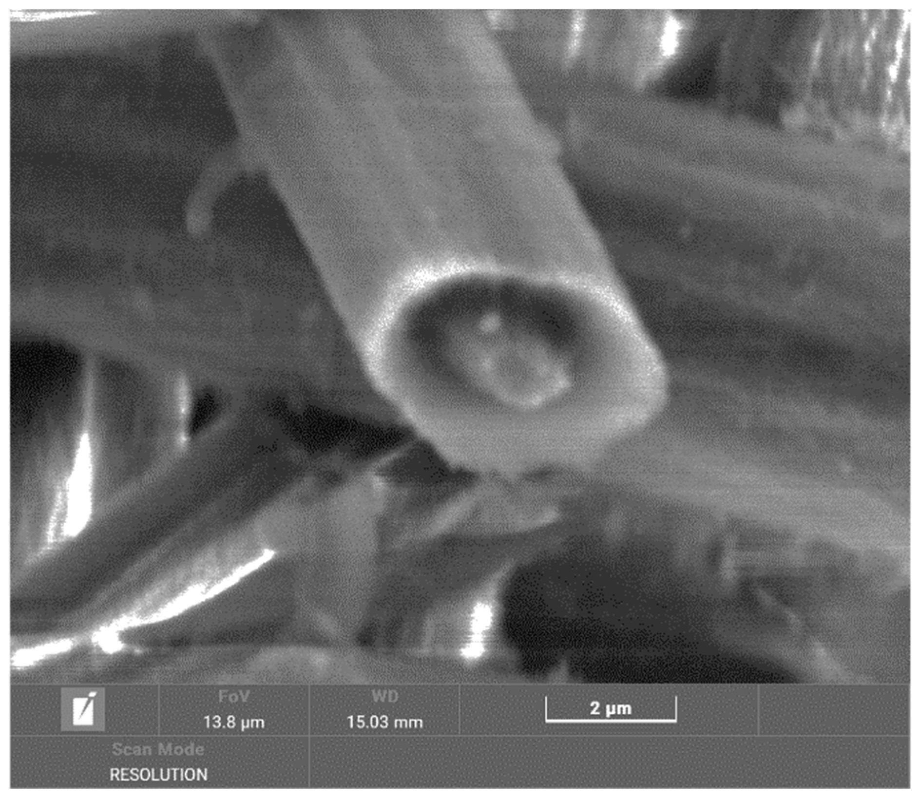
In the temperature range of up to 700 °C, surface changes are visible on the fibers (
Figure 11), and there are changes inside the fibers when cavities are formed. The surface of the fibers is rough compared to virgin fibers, which may be caused by degradation in the presence of by-products of the combustion of the polymer matrix. These combustion products then act as degradation agents. In the detailed image in
Figure 12, very fine structures are visible on the fiber surface, which are created in parallel at higher temperatures during combustion without a protective atmosphere. However, they are not as clearly visible as in the case of a tube.
Carbon fibers exhibit excellent thermal resistance; however, their behavior changes significantly in oxidizing environments such as air. Below 400 °C, they remain stable, with only minor degradation. The surrounding epoxy resin softens and partially decomposes, while the fibers maintain their structural integrity, aside from potential minor surface oxidation at the defect sites. Between 400 °C and 600 °C, the epoxy matrix combusts, initiating slow oxidation of the fibers, particularly at amorphous regions and graphitic edges. In the 600–700 °C range, the oxidation rate increases rapidly, leading to surface roughening, thinning, and mechanical weakening. Structural alterations within the fiber walls become evident. At 700–800 °C, deep oxidation occurs, causing fragmentation and the formation of needle-like carbon nanostructures resembling nanotubes. Above 800 °C, complete oxidation takes place, resulting in CO and CO
2 emissions and near-total disintegration of the fibers. This highly exothermic process also poses environmental and health risks due to the generation of airborne nanostructures [
29,
35,
36,
37,
38,
39].
4. Discussion
The evaluated composite chip formed during the drilling of a tube and a plate was created with an uncoated tool at a cutting speed of v
c = 120 min
−1. The selected cutting tool is a standard the manufacturer recommends for machining composites.
Figure 13,
Table 2, and
Table 3 show a clear difference between the weight loss of the composite chip formed during the drilling of a tube and a plate within the individual temperature intervals. Composite chips formed during the drilling of a plate degraded faster than chips from a tube, which is evidenced in all cases by a higher weight loss of the material in the evaluated temperature intervals. Up to a temperature of 600 °C, these are differences in units of percent; in the temperature interval of 600–700 °C, this is 38%. This significant difference indicates that the carbon fiber is decomposed here since the resin is already decomposed. At a temperature of 800 °C, the chip from the plate is completely burned, while the chip from the tube is still partially preserved [
29,
30].
This fact can be explained by the differences in the drilled blanks in production quality (production versus laboratory preparation), the materials used (resins and hardeners), and the ratio of carbon reinforcement to matrix. With a higher proportion of matrix, its degradation will occur more easily, and subsequently, the carbon fibers will be degraded more easily and intensively. In the case of a larger amount of matrix, a larger amount of by-products will be formed, which will have a negative effect on the carbon fibers.
The most common by-products generated during the combustion of standard epoxy matrices are carbon monoxide (CO), carbon dioxide (CO
2), nitrogen dioxide (NO
2), hydrogen cyanide (HCN), alkylated phenols, and aromatic ethers. These products and their amounts will affect the surface degradation of the carbon fibers and the degradation of fibers throughout their volume. If the amount of matrix is higher, more of these products will be formed, supporting and accelerating the combustion process, including the degradation of carbon fibers. The combustion rate is also related to the process of carbon fiber degradation itself, which was specifically evaluated in this work. As mentioned, a difference was found between different samples. The greater the epoxy matrix present, the faster its loss during combustion. The fibers were practically preserved up to a temperature of 600 °C. Above this temperature, their surface degradation occurred due to the formation of by-products of resin combustion and internal degradation, which was noticeable as the formation of a cavity along the entire length of the fibers. The obtained results are confirmed by other studies that have shown that epoxy resin degradation in composites produces significant amounts of volatile organic compounds, including aldehydes, ketones, and carboxylic acids, alongside CO, CO
2, NO
x, and SO
x. Therefore, composites with a higher epoxy content generate more combustion by-products, which in turn accelerates the oxidative attack and structural damage of carbon fibers [
11,
32].
After surface degradation, the diameters of the fibers decreased. These fibers would be mechanically unusable. At a temperature of 700 °C, the formation of a fine structure was simultaneously recorded (
Figure 11). A fine structure in the form of soot is mentioned in several professional publications. However, the formation of soot and not the formation of ordered structures is reported. In the case of the measurements performed, fibrous structures similar to carbon tubes are visible from the microscopic images (
Figure 14) [
26].
In the case of chips made from a tube (different material and with a lower polymer matrix content), the stability of the sample in terms of weight loss was higher, which proves that with a lower amount of matrix, the material burns less and is therefore more stable.
Table 2 summarizes the weight loss of the composite chips from the evaluated blanks at a cutting speed of v
c = 120 min
−1. There is an apparent difference between the weight losses of the two different materials. The composite chip from a tube with a smaller matrix is more thermally stable than the laboratory-made plate. Based on these results,
Table 3 is presented, which provides information on the fiber diameters in both cases and their changes under thermal load.
The character of the surface of the fibers varied at 700 °C. In the case of the plate at 700 °C, the fibers were surface-oxidized and a cavity formed inside the fibers. At 800 °C, the fibers from the plate no longer existed. In the case of the tube at 700 °C, the fibers were surface-oxidized and a cavity formed inside the fibers; at 800 °C, the diameter of the fibers increased, probably due to their disintegration into finer submicron structures (
Figure 15). Modified in
Table 3, letters a and b are explained below.
Although CFRPs exhibit partial fire resistance due to their high fiber content and compliance with flammability standards, this study demonstrates that their thermal decomposition in oxidative conditions can still result in the release of hazardous nano- and microparticles not captured by conventional fire testing protocols [
28].
5. Conclusions
This study evaluated the influence of the oxidative environment during the combustion of chips generated during the machining of composite materials with carbon fibers. The following conclusions can be drawn from the obtained results:
Complete combustion of epoxy resin occurs between temperatures of 500° and 600 °C. This is the temperature at which the polymer matrix is burned, and at the same time, there is no degradation of the carbon fiber. Complete burning of the epoxy resin corresponded to the processes carried out in a protective atmosphere.
Based on the experiments, it was found that the combustion temperature depends on the ratio of carbon fibers and epoxy resin, its type, and the production method of the composite sample. A higher resin content logically creates a larger amount of combustion products, which accelerates the degradation process.
When a temperature of 700 °C is reached, combustion without a protective atmosphere leads to surface degradation of the fibers and degradation inside the fibers, resulting in the formation of carbon tubes.
At higher temperatures, the carbon fibers’ diameters increase, they disintegrate, and very fine needle-like formations occur with diameters of hundreds of nanometers and lengths of tens of micrometers. Simultaneously with this decomposition, nanostructured formations, which could be carbon nanotubes, were microscopically identified.
The decomposition of carbon fibers and the resulting formation of nanostructures at a temperature of 800 °C in an oxidizing atmosphere are significant results that will be further developed and studied. This finding is very notable, especially for rescue services in the case of aircraft and car fires, where composite systems are used more extensively.


 ,
, 


