1. Introduction
Over the past few decades, carbon fiber-reinforced polymers (CFRPs) have gained widespread use across multiple industries due to their high strength-to-weight ratio, fatigue resistance, and durability. These properties make them highly suitable for structural applications in aerospace, automotive, marine, civil engineering, sports equipment, and renewable energy sectors [
1,
2]. In these contexts, CFRPs help enable lightweight structures that reduce fuel consumption, increase payload efficiency, and enhance design flexibility. Among CFRP systems, thermosetting composites—particularly epoxy-based CFRPs—are the most used, given their excellent mechanical strength, thermal stability, and chemical resistance [
3]. Such materials are found extensively in aircraft fuselages, structural panels, wind turbine blades, and vehicle body components.
However, thermoplastic CFRPs are emerging as viable alternatives due to their shorter processing cycles, damage tolerance, and, importantly, recyclability. These developments reflect a growing shift in the materials industry toward circularity and sustainability, especially as environmental regulations become more stringent and industries face increasing pressure to reduce carbon footprints. In parallel, the accelerated demand for carbon fiber composites has led to a corresponding surge in CFRP waste generation, creating both a waste management challenge and an opportunity for material recovery and reuse.
Recent studies estimate that approximately 31,000 tons of CFRP waste are generated annually worldwide, a number projected to rise sharply as more CFRP-intensive components reach end-of-life (EoL) status. By 2050, Europe alone could accumulate an estimated 190,000 tons of CFRP waste, with the aerospace and wind energy sectors contributing the most. Despite growing awareness, current recycling and waste management practices remain limited in scope and efficiency. In some regions, over 35% of CFRP waste is still landfilled, and only 20% is recycled and 2% reused [
4]. These figures underscore a significant materials and environmental gap: while carbon fiber is an expensive, high-performance material with high embodied energy, a large fraction is discarded, resulting in economic loss and environmental impact. Moreover, projections indicate that global carbon fiber demand will outpace supply by 2030, further emphasizing the need to reclaim and repurpose CFRP waste.
To address this issue, several recycling methods have been developed or are currently under evaluation. These include mechanical, thermal, and chemical recycling approaches, each with distinct advantages and challenges. Mechanical recycling is the most cost-effective and industrially accessible technique. It involves physically shredding, crushing, or grinding CFRP waste into smaller pieces without separating the fiber and matrix phases. Initial coarse shredding reduces the material to particle sizes of 50–100 mm, followed by fine grinding to produce powders ranging from sub-millimeter to tens of microns. These powders, although heterogeneous, retain functional characteristics—such as residual stiffness, conductivity, and thermal resistance—and can be reused as fillers or reinforcements in new composite systems [
2,
5].
Thermal recycling, notably pyrolysis, involves heating CFRP waste in an inert or oxygen-limited environment to decompose the polymer matrix and recover carbon fibers. This method is well-established in industrial settings and is capable of reclaiming long, continuous fibers. However, the process often leaves residual char on fiber surfaces, which negatively affects fiber–matrix adhesion in new composites [
6]. More advanced thermal methods, such as microwave-assisted pyrolysis or fluidized bed systems, aim to reduce energy input and improve fiber quality but remain under evaluation for scalability and cost-effectiveness [
7]. Chemical recycling, or solvolysis, offers a more refined approach by using high-temperature solvents or supercritical fluids to selectively depolymerize the resin matrix. While this method can yield high-purity recovered fibers and even recover matrix constituents, it often requires hazardous reagents and sophisticated equipment, limiting its commercial viability [
8].
While most recycling techniques aim to extract clean, reusable fibers, another promising direction involves the functional reuse of the full CFRP waste, including both fiber and resin phases, as hybrid reinforcement systems. This approach leverages the fact that mechanically milled waste consists of fragmented carbon fibers embedded in thermoset resin particles. When ground to fine particle sizes and subjected to appropriate thermal and pressure conditions, this hybrid material can be reactivated—partially through softening or degradation of the residual matrix—and consolidated into dense, self-supporting forms [
9]. This strategy eliminates the need for fiber separation or virgin additives and enables the design of new composite architectures with tailored multifunctional properties.
One critical functional property of interest is electrical conductivity, particularly through the thickness of composite laminates. In aerospace applications, such as lightning strike protection, structural health monitoring, and electromagnetic interference (EMI) shielding, through-thickness electrical conductivity is essential [
1]. However, conventional CFRPs are inherently anisotropic and electrically insulating in the through-thickness direction due to the non-conductive polymer matrix and the alignment of carbon fibers primarily in-plane. Bridging this conductivity gap typically requires embedding conductive pathways across the laminate, which presents both technical and economic challenges.
Traditionally, this has been addressed by incorporating conductive nanofillers—such as carbon nanotubes (CNTs), carbon nanofibers (CNFs), or graphene derivatives—into the matrix or interlaminar regions [
10,
11,
12,
13]. These fillers can be introduced via solution blending, vacuum-assisted resin transfer molding (VARTM), or electrostatic and magnetic field-assisted alignment [
14,
15]. While effective, these techniques often rely on costly virgin nanomaterials and complex processing conditions. Furthermore, the sustainability of using nanofillers remains questionable when considering the overall life cycle impact and resource constraints.
Recent studies suggest that recycled CFRP waste itself can serve as a conductive additive. For example, the use of chopped or milled recycled fibers has been shown to significantly enhance electrical conductivity in epoxy-based matrices, sometimes surpassing the performance of virgin fillers [
16,
17]. These gains are highly dependent on filler morphology, dispersion, alignment, and interfacial bonding quality [
18,
19]. Yet, much of the current literature focuses on using recycled fibers as additives rather than as bulk structural elements.
In this context, a sustainable and scalable alternative involves repurposing CFRP machining waste directly as a functional core material in sandwich composite structures. This approach not only reduces the need for virgin materials but also provides an opportunity to exploit the inherent conductivity and structural potential of recycled carbon-rich waste. Additionally, it bypasses the complexity of fiber recovery and purification by directly molding the waste material into usable forms.
Building upon this idea, the present study investigates the use of mechanically ground CFRP machining waste—collected from aerospace-grade composite machining operations—as the core layer in multifunctional sandwich panels. The waste, composed of carbon fibers, fragmented thermoset resin, and trace contaminants, was processed through direct compression molding without the use of additional binders, virgin fillers, or curing agents. This process, previously developed by the authors [
20,
21], leverages incipient thermal degradation, surface bond activation, and residual resin reactivity to achieve particle consolidation. This is primarily due to the mechanical shear and frictional heat generated during grinding, which can locally raise the temperature and mobilize residual unreacted epoxide or hardener groups. These conditions may induce secondary crosslinking reactions or softening of the network, particularly in systems that were initially under-cured or contain excess reactive functionalities [
22,
23].
The resulting molded plates were integrated with external skins made from recycled CFRP prepreg to create sandwich structures. The primary focus of this study is to evaluate the through-thickness electrical conductivity and mechanical performance of the fabricated panels and to assess the potential of this process as an environmentally responsible and industrially viable recycling pathway. By demonstrating comparable or superior conductivity to systems containing virgin nanofillers, this research contributes to advancing circular economy goals while enabling the development of multifunctional composite structures from waste-derived materials [
24].
2. Materials and Methods
2.1. Supplied Materials
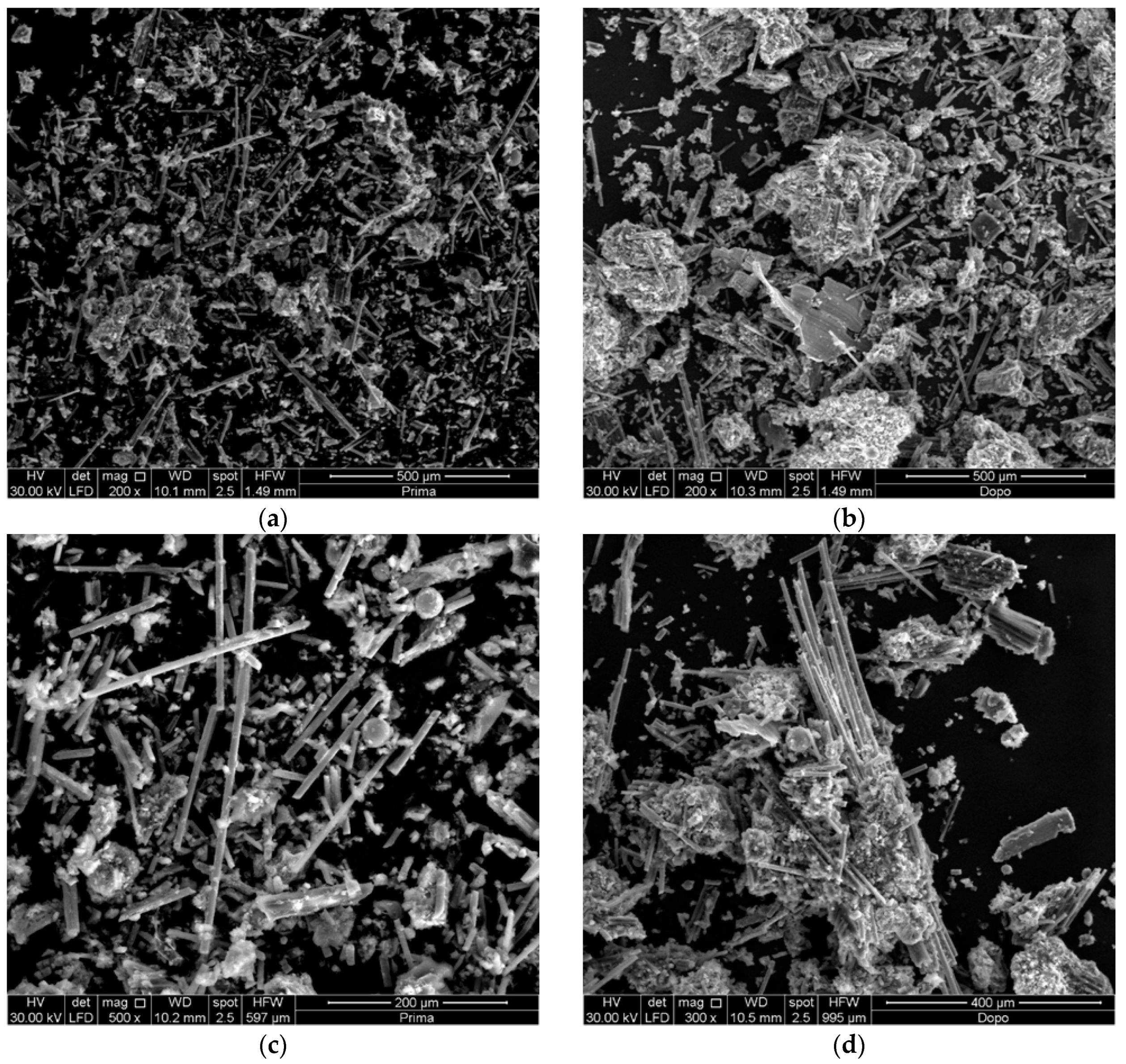
A carbon fiber-reinforced (CFR) sandwich panel was fabricated using recycled commercial materials. Ground carbon fiber-reinforced polymer (CFRP) scraps were recovered from an aerospace manufacturing facility, where they were generated during the dismantling and end-of-life processing of CFRP structures. As machining waste from certified aeronautical parts, the material is inherently heterogeneous, comprising carbon fibers and cured epoxy matrix fragments. Due to its complex and variable nature, detailed ultimate and proximate analyses were not conducted; however, the composition aligns with typical aerospace-grade CFRP materials. Specifically, the material was collected immediately after the grinding phase, during which both particle size and external contamination levels were highly variable. The machined CFRP components consisted of a thermosetting epoxy matrix reinforced with carbon fibers. Initially, the recovered scraps were sieved using a Retsch AS 200 (Retsch GmbH, Haan, Germany) basic sieve shaker equipped with two mesh sieves: the first with a 4 mm opening and the second with a 1 mm mesh. This procedure enabled the collection of powder with particle sizes smaller than 1 mm, achieving a yield of approximately 30%. The heterogeneity of the powder is clearly visible in the stereoscopic images acquired using a Leica S9i stereo microscope (Leica Camera AG, Wetzlar, Germany) after sieving. The particle size distribution of the sieved powder was further analyzed using the Leica S9i stereo microscope. Finally, Hexcel’s HexPly M49/42%/CHS-3K CFR prepregs (Hexcel Corporation, Stamford, CT 06901, USA), featuring a plain woven fabric with a nominal epoxy resin content of 42 wt%, an areal density of 200 g/m2, and a thickness of approximately 350 μm, were used as the external prepreg skins in the sandwich panel. This high-performance 0°/90° woven cloth prepreg is commonly employed in aeronautical applications.
2.2. CFRP Panel Fabrication Procedure
Recycled CFRP specimens were fabricated via direct compression molding of the industrial CFRP powder, without the addition of virgin polymer or binding agents, following the processing scheme illustrated in
Figure 1. Square samples (84 × 84 mm
2) were molded and two different panels were produced: one made entirely of recycled CFRP powder (labelled core alone), and the other incorporating a single external CFRP prepreg ply on both the top and bottom surfaces (labelled sandwich). The molding process was carried out in a hot plate press by ATS FAAR (Cassina dè Pecchi, Italy) with a maximum load of 264 kN and the plate size of 300 × 300 mm
2, where the upper plate was maintained at 250 °C and the lower at 220 °C. This temperature difference between the upper and lower platens was required due to the specific molding setup and the type of mold used, for example, to account for the differing thickness in the aluminum mold’s upper and lower parts, creating a controlled temperature gradient. This gradient promotes resin softening and flow within the recycled CFRP powder, enhancing particle bonding and consolidation during compression molding. This parameter selection is consistent with the authors’ previous work on recycled CFRP processing [
21]. The selected scraps from aeronautical CFRP components were placed into an aluminum mold featuring an internal cavity of 84 × 84 mm
2. A pressure of 1.5 bar was applied for 15 min. To prevent adhesion between the recycled material and the mold surfaces, a fluorinated ethylene propylene (FEP) release film was applied to both the top and bottom interfaces. Upon completion of the cycle, the mold was allowed to cool to ambient temperature inside the press before demolding the samples. In the direct molding of CFRP powder, elevated temperatures are essential to activate polymer segment mobility and facilitate particle bonding, while sufficient pressure improves interparticle contact and densification.
2.3. Thermal Analysis
The sifted powder and the hot-compacted samples were thoroughly characterized using thermal and thermomechanical analyses to determine the key thermal properties of the raw material and to highlight the effects of the manufacturing process.
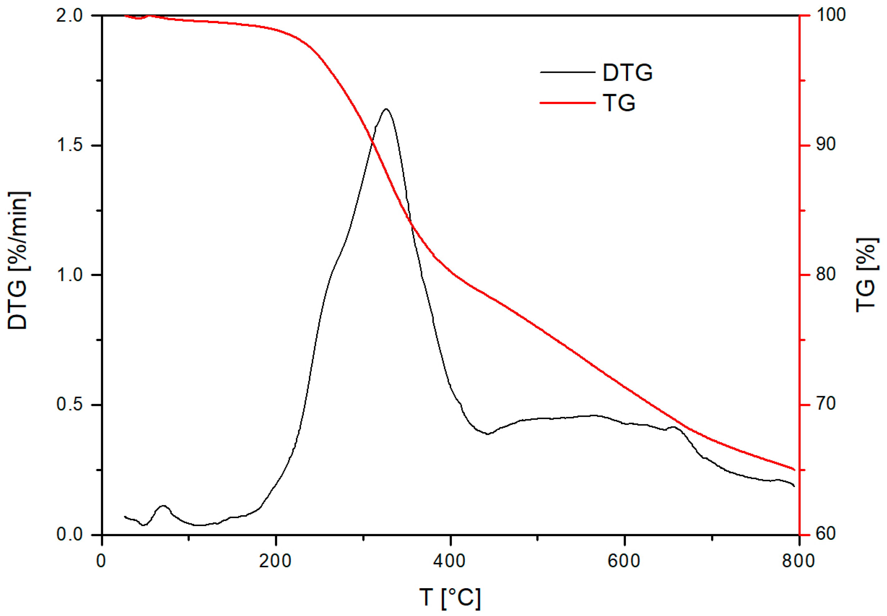
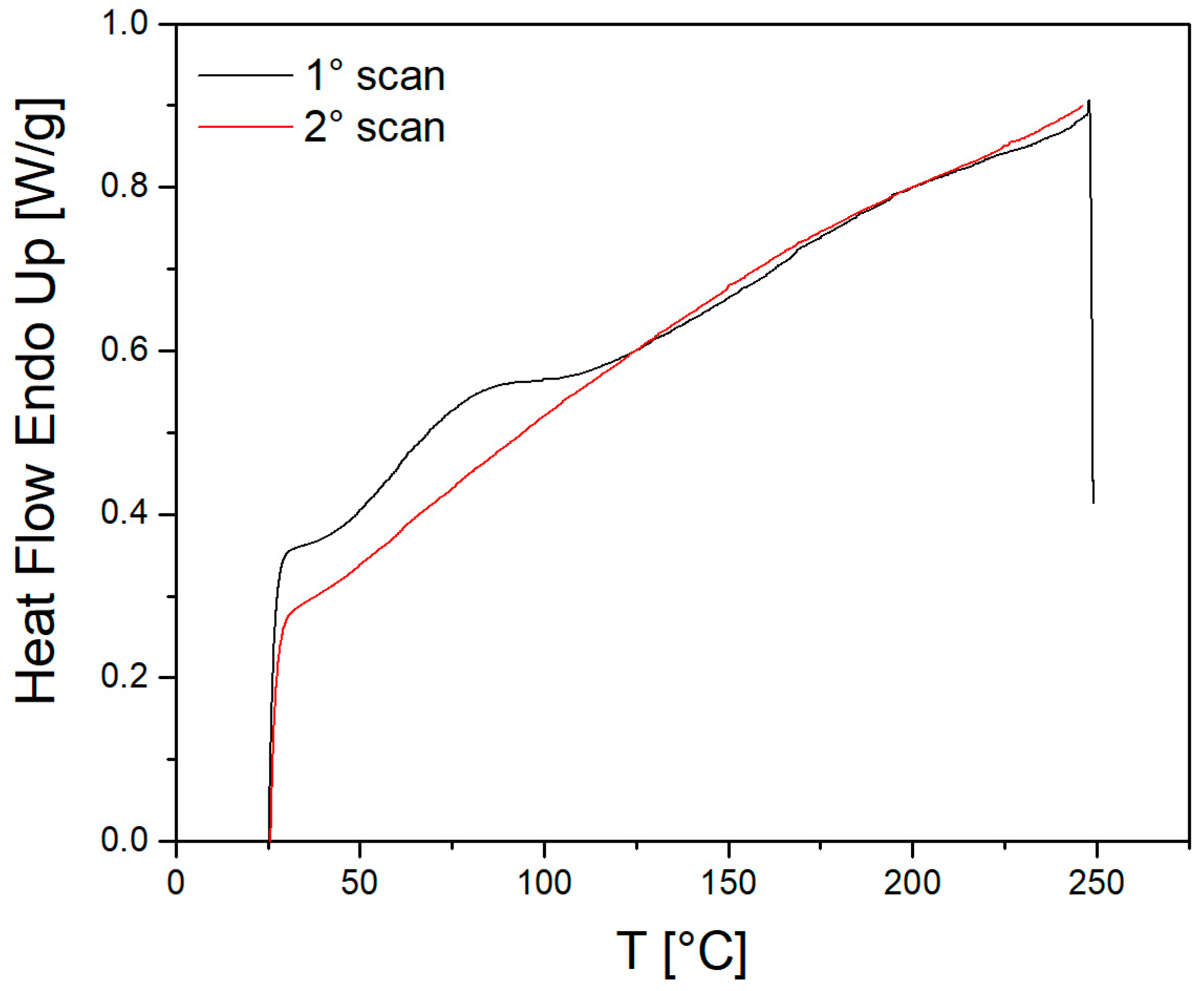
Thermogravimetric analysis (TGA) was performed on the sifted powder using a Perkin Elmer TGA instrument (PerkinElmer, Shelton, CT, USA) under a nitrogen atmosphere. The sample was heated from 25 °C to 800 °C at a rate of 10 °C/min to quantify the inorganic fiber content present in the mixture. Differential scanning calorimetry (DSC) was conducted using a TA Q2000 system following a standard three-step protocol: an initial heating from 25 °C to 250 °C, a cooling phase back to 25 °C, and a second heating cycle identical to the first, all at a rate of 10 °C/min, with the Tg value determined from the second heating cycle to minimize the influence of the material’s thermal history. This analysis was carried out on the sifted powder.
2.4. Electrical Conductivity Measurement
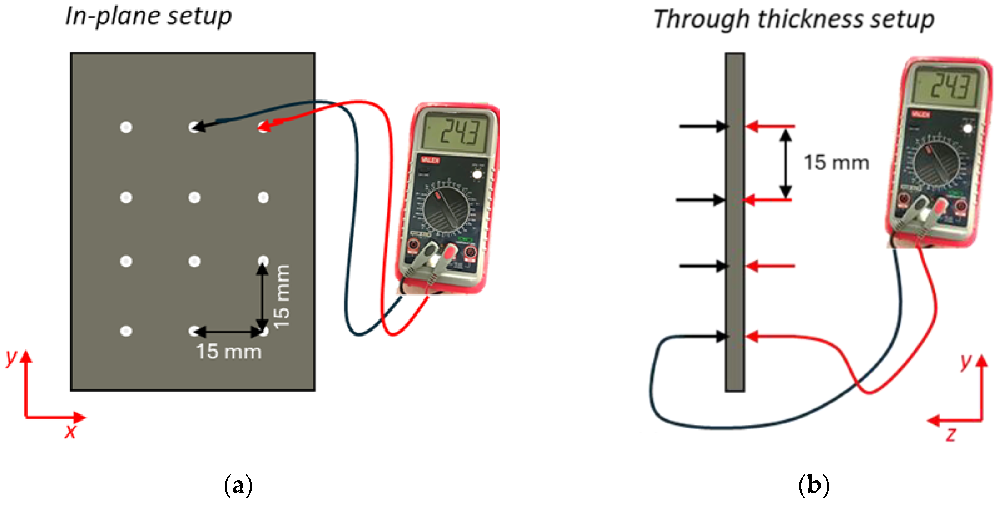
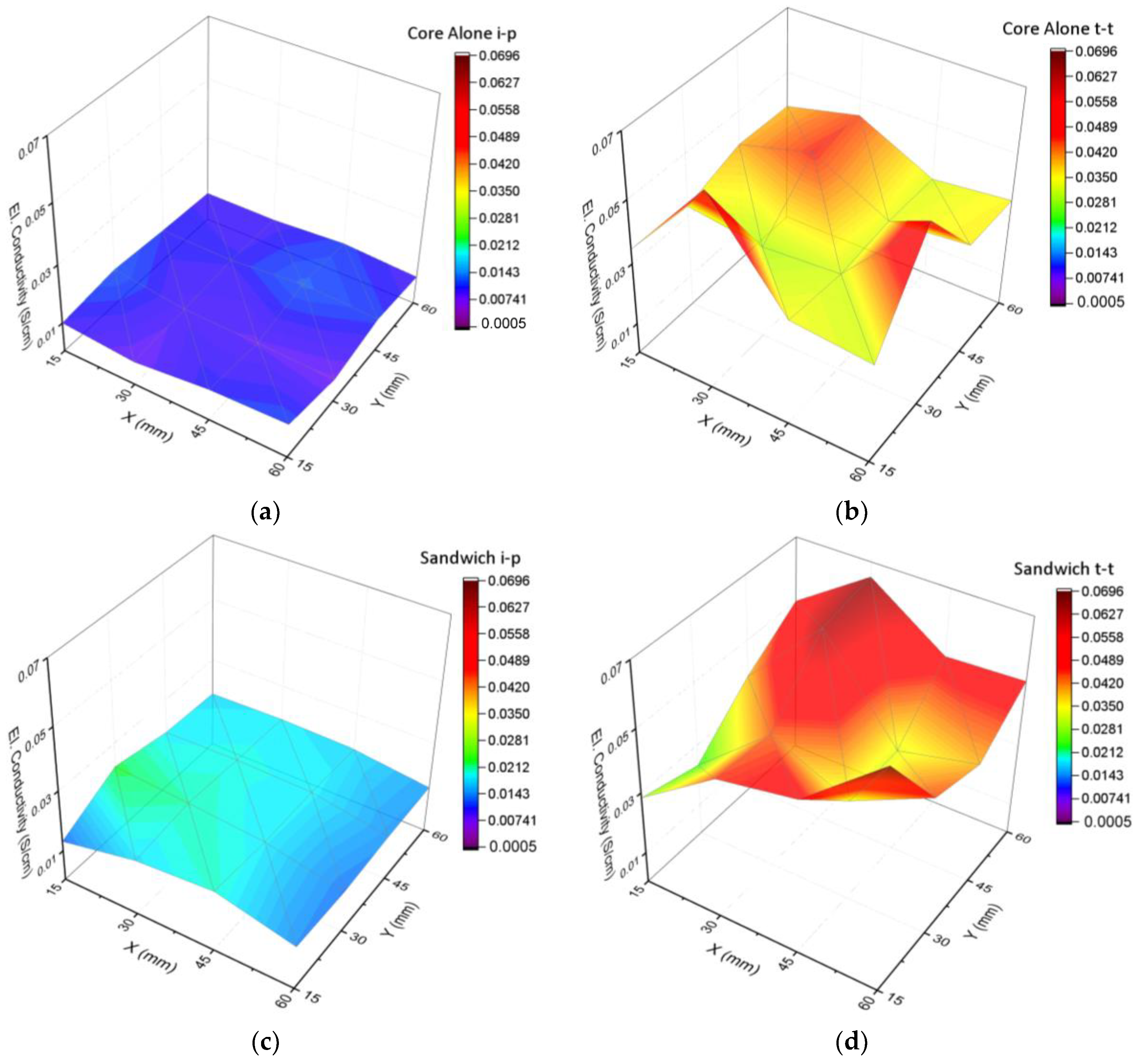
To assess the improvements in through-thickness electrical conductivity of the fabricated composite structures, measurements were performed using a Valex digital multimeter with standard probes. Prior to each measurement, the probes were cleaned to ensure consistent contact quality. No additional surface treatments, such as oxide layer removal, were applied to the sample surfaces. Electrical resistance was recorded in both the in-plane and through-thickness directions, with the two probes positioned according to the configurations shown in
Figure 2. For through-thickness (z-direction) measurements, the probe spacing corresponded to the panel thickness. The probe tips were placed perpendicularly to the surface and aligned along the same vertical axis to minimize misalignment and ensure measurement accuracy. For the in-plane (x–y plane) electrical conductivity measurements, the probes were placed directly on the sample surface, positioned perpendicular to the panel face, and spaced 15 mm apart along the surface. This configuration enabled many measurements—over 30 acquisitions—across the panel surface. Electrical conductivity values were then calculated by normalizing the measured conductance with respect to the probe tip spacing.
2.5. Microstructural Observation
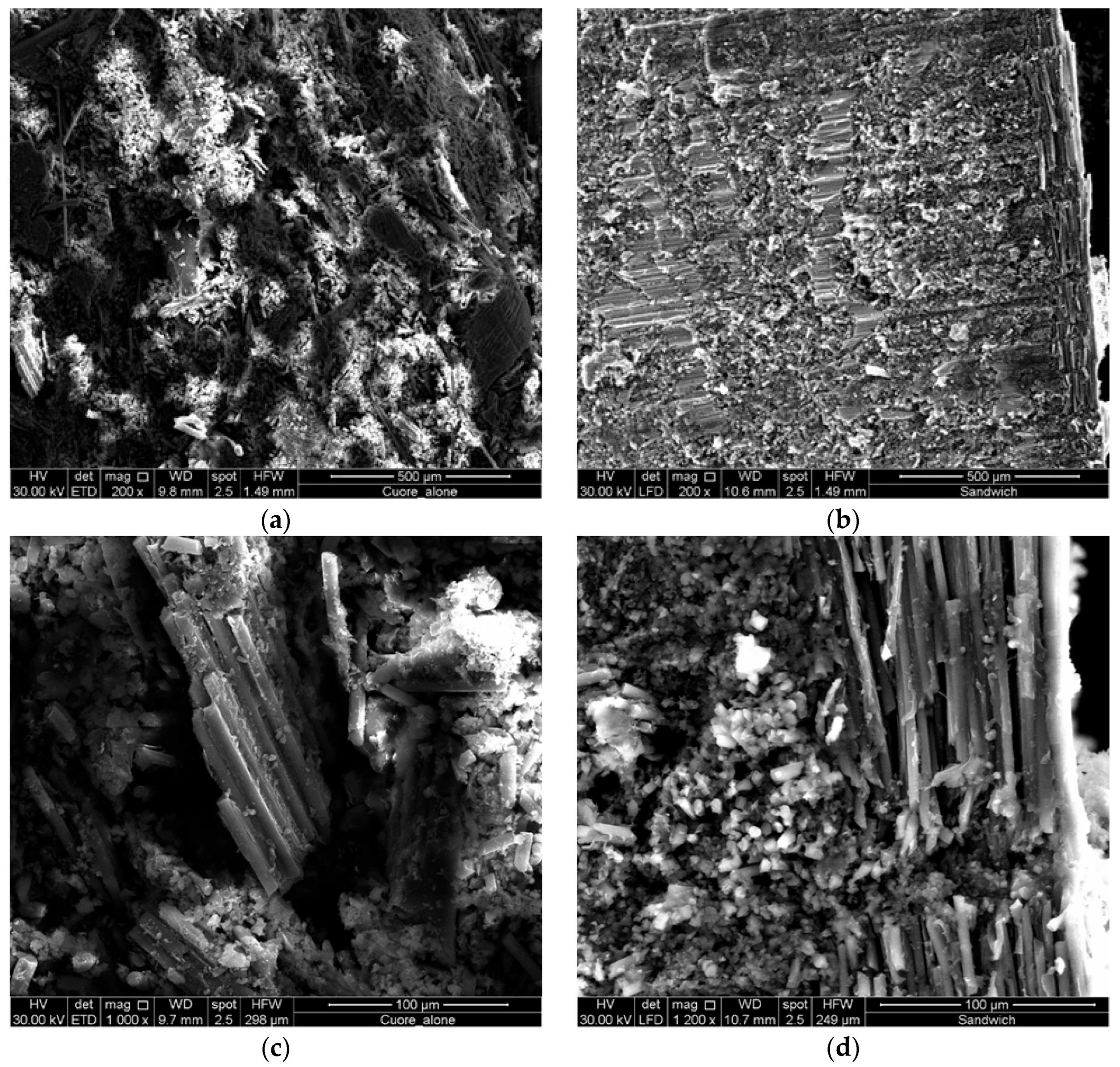
To investigate the quality of internal adhesion, fiber embedding, and the formation of interfacial regions within the composite structure, a comprehensive morphological analysis was carried out using scanning electron microscopy (SEM) (FEI Quanta 200 F, Zurich, Switzerland. Samples were cryo-fractured in liquid nitrogen to preserve the microstructural integrity and reveal the fracture surfaces representative of the bulk material. Prior to imaging, all specimens were sputter-coated with a thin conductive layer of gold–palladium to prevent charging effects during SEM analysis. SEM observations were performed using a high-resolution field-emission scanning electron microscope) operating under high vacuum conditions at an accelerating voltage of 30 kV. The analysis focused on evaluating the dispersion and embedding of carbon fibers within the polymer matrix, the degree of interfacial bonding, and the presence of voids or delamination at the matrix–fiber interfaces.
In addition to cross-sectional imaging of the sandwich composites, SEM was also used to examine the morphology of the sieved powders, as well as powders produced by mechanical grinding of hot-compacted core samples. These comparative observations provided insight into the structural evolution of the recycled material from its raw state through the compaction and consolidation process.
2.6. Thermomechanical and Mechanical Testing
The density of the molded composite samples was determined by precisely measuring their physical dimensions and corresponding masses. These measurements were used to calculate the bulk density using the standard mass-to-volume ratio.
To assess the mechanical performance of the fabricated specimens, three-point bending tests were performed in accordance with the ASTM D7264 standard [
25]. Testing was carried out using an MTS Insight 5 electromechanical universal testing machine (MTS Systems S.r.l, Torino, Italy), operated in displacement-control mode with a constant crosshead speed of 1 mm/min. The support span was set to 40 mm and a minimum preload (1 N) was applied. During each test, both the applied load and mid-span deflection were continuously recorded. These data were used to compute key mechanical parameters, including the flexural strength, maximum deformation at failure, and flexural modulus, following the equations provided by ASTM D7264. The results provided critical insights into the stiffness, load-bearing capacity, and overall structural integrity of the recycled and reference composite sandwich panels under flexural loading.
Moreover, dynamic mechanical analysis (DMA) was performed on both the standalone core (core alone) and the complete sandwich composite samples to evaluate their viscoelastic behavior and gain insights into the effect of the sandwich architecture on thermal–mechanical performance. The objective of this investigation was to characterize how the recycled core material and the outer CFRP skins influence the stiffness and damping capacity of the composite system over a broad temperature range, in addition to its glass transition temperature (Tg). The tests were carried out using a Perkin Elmer Pyris Diamond DMA instrument (PerkinElmer, Shelton, CT, USA) in dual cantilever bending mode. Five rectangular specimens (40 × 10 mm2) were cut from each panel type and subjected to a controlled temperature sweep from 25 °C to 250 °C at a constant heating rate of 3 °C/min. The storage modulus (E′) and tan delta (E″/E′, with E″ loss modulus) were continuously recorded as a function of temperature. These parameters provide crucial information on the stiffness, energy dissipation, and thermomechanical transitions of the materials, allowing for direct comparison between the performance of the recycled core and the reinforced sandwich configuration.
4. Discussion
CFRP particles with a thermoset matrix can be effectively consolidated using the direct molding technique, and this study provides further confirmation of this technological principle. However, contributions in the scientific literature on this topic remain limited, particularly when it comes to rigid thermoset particles [
26]. While the direct molding of elastomeric materials is facilitated by the deformability of the particles under pressure—leading to reduced final porosity—the scenario is different for rigid particles. Their limited deformability results in poor inter-particle contact during molding, often causing higher porosity and lower mechanical performance compared to elastomer-based systems (e.g., rubber from tires) [
28]. Although rigid particles soften at elevated molding temperatures, aiding in agglomeration, this mechanism alone is insufficient for optimal compaction. Therefore, ensuring good contact between the poured powder and the mold punch surface at the end of filling is critical. If this contact is not uniform, some regions of the recycled part may become over-compressed, while others remain under-compacted and mechanically weak.
Specifically, the TGA and DTG analyses reveal that the recycled CFRP powder retains a high proportion of inorganic material (~65% at 800 °C), mainly carbon fibers and metallic residues. A major thermal degradation peak around 327 °C confirms the presence of epoxy resin, typical of aerospace-grade CFRPs. A minimal initial mass loss (~2%) suggests low moisture and minimal volatile contamination. DSC analysis indicates residual reactivity of the matrix. The increase in glass transition temperature (Tg) from ~75 °C to 130 °C between the first and second scans points to post-curing behavior, confirming that some reactive groups remain in the material. This justifies the selection of a 250 °C molding temperature to encourage polymer mobility and effective particle agglomeration.
At a first visual inspection of the molded panels, the surfaces were compacted and clean, with minimal or no particle shedding, indicating actual agglomeration of the direct molding process. These outcomes highlight the influence of the processing parameters—specifically molding pressure, temperature, and holding time—on the consolidation and quality of the recycled core material, even when starting from the same type and amount of composite waste with similar residual reactivity [
21]. A higher molding pressure improves interparticle bonding and overall mechanical performance. However, the intrinsic compressibility of the material sets a limit, as excessive pressure may yield diminishing returns. Similarly, elevated molding temperatures enhance polymer flow and compaction due to reduced viscosity, yet excessively high temperatures can induce thermal degradation of the matrix. A controlled level of degradation during processing facilitates the formation of new bonds between particles. However, excessive degradation can lead to microcracking within the polymer matrix. Furthermore, elevated temperatures may result in the release of volatile organic compounds (VOCs) or even initiate combustion. For these reasons, an optimal combination of molding parameters—temperature, pressure, and dwell time—was carefully established. Microscopic analysis also confirmed the successful consolidation of the laminate at the end of the autoclave molding process. Strong adhesion between the carbon fiber-reinforced (CFR) outer skins and the recycled thermoset core is facilitated by resin bleeding, which fills surface cavities and micro-voids, enhancing interfacial bonding.
Microscopic and SEM analyses confirm successful compaction of the recycled powder under the selected processing conditions. The core-alone and sandwich structures both exhibit dense, well-bonded matrices with uniform fiber distribution and strong fiber–matrix adhesion, indicating effective consolidation. The sandwich panel shows greater microstructural homogeneity, likely due to the compressive effect of the outer CFR skins. No delamination is observed at the skin–core interface, indicating excellent mechanical integrity. Pre-existing fiber bundles and metallic inclusions (mainly aluminum) in the powder contribute to mechanical reinforcement and heterogeneity but may locally influence performance. In recycled CFRP composites with shredded or ground waste cores, interfacial adhesion is crucial for mechanical integrity. Recycling can cause surface contamination, fiber damage, and poor wetting, reducing load transfer efficiency. Although this study did not apply surface treatments, the literature shows that methods like plasma treatment [
29] and chemical grafting with silane agents or oxidative treatments [
30] can enhance fiber–matrix bonding. These approaches are especially relevant for compression-molded structures, where heterogeneous interfaces from thermoset residues and fiber fragmentation are common. Future work will systematically assess these surface treatments’ effects on interfacial strength using micromechanical tests such as interlaminar shear and fiber pull-out, aiming to optimize the recycled CFRP sandwich-structure performance.
These first results demonstrate that the recycled CFRP powder maintains high thermal stability and structural integrity and exhibits residual chemical reactivity useful for thermomechanical reprocessing. Consequently, this could be an effective way to reuse and to produce dense, cohesive composite panels with promising mechanical properties.
In terms of electrical conductivity, while good electrical conductors typically exhibit conductivities above 102 S/cm, the composite panel falls within the semiconductive range (10−8–102 S/cm), qualifying it as a functional material with potential for electromagnetic or antistatic applications. In the core-only structure, these networks are formed by randomly oriented, fragmented carbon fibers in direct contact with each other and with partially conductive thermoset resin remnants. However, the lack of long-range fiber alignment and limited compaction during molding restricts the efficiency of the conductive pathways, particularly in the through-thickness direction. In contrast, the sandwich structure, which incorporates external CFRP prepreg skins, exhibits improved conductivity due to enhanced fiber continuity at the interfaces and better compaction. The prepreg skins facilitate denser packing and improved interfacial bonding during compression molding, effectively reducing inter-particle gaps and increasing the number of conductive contact points across the thickness. Quantitatively, the core-only panel demonstrated an average through-thickness conductivity of 0.04 S/cm, while the sandwich structure achieved 0.045 S/cm. This represents a 12.5% increase in conductivity, highlighting the role of the external skins in facilitating more efficient electrical percolation through the laminate. This level of conductivity demonstrates that the recycled machining waste can impart functional electrical properties comparable to those achieved with more conventional conductive fillers, thereby supporting the use of recycled materials in applications such as EMI shielding and lightning strike protection.
These findings suggest that, beyond mechanical reinforcement, the addition of CFRP prepreg skins contributes to the development of more continuous and robust conductive networks, enhancing the multifunctionality of recycled CFRP sandwich panels. The enhancement in through-thickness conductivity is primarily attributed to the presence of short, randomly oriented recycled carbon fibers—originating from machining waste—which form conductive pathways during the hot press molding process. Further improvements could be achieved by aligning fibers preferentially in the through-thickness direction, although such an approach would introduce additional complexity to the manufacturing process.
Additionally, the thermomechanical and mechanical results underline the higher storage modulus and flexural modulus of the sandwich panel, showing the reinforcing effect of the external CFRP prepreg skins. The CFRP skins contribute to the overall stiffness and mechanical integrity of the structure. In particular, the enlarged modulus values in the glassy region settle the proper interaction between the co-molded core and prepreg skins. So, the core-alone panel displays a lower E′, more associated with the discontinuous structure of the initial material (CFRP powder from scraps) which contributes less resistance to deformation due to the absence of continuous fiber reinforcement. The Tg range is similar in both panels, suggesting that the matrix polymer is chemically comparable. However, the difference above Tg emphasizes the importance of configuration design. In fact, the core alone provides limited structural stiffness, but its integration into a sandwich structure enhances load-bearing capabilities due to the stiff outer layers and sandwich synergy. These findings emphasize the potential of co-molding recycled CFRP powder within a sandwich configuration to recover mechanical performance suitable for semi-structural applications. The higher tan δ peak in the core-alone panel suggests increased molecular mobility and energy dissipation capacity, likely resulting from a lower crosslink density or the more heterogeneous microstructure of the recycled CFRP powder. These features can arise due to incomplete polymerization or local variations in the recycled matrix. In general, the sandwich structure offers superior stiffness and thermal stability across the tested temperature range. The enhanced modulus and delayed transition behavior make it a more suitable candidate for structural applications where mechanical performance at elevated temperatures is critical. Meanwhile, the core-alone panel, although less stiff, still presents moderate viscoelastic performance, highlighting the potential of recycled CFRP powders for cost-effective and sustainable core materials. Thus, the material is well-suited for secondary structural applications, especially where good thermal resistance, semiconductor properties and mechanical strength are required.
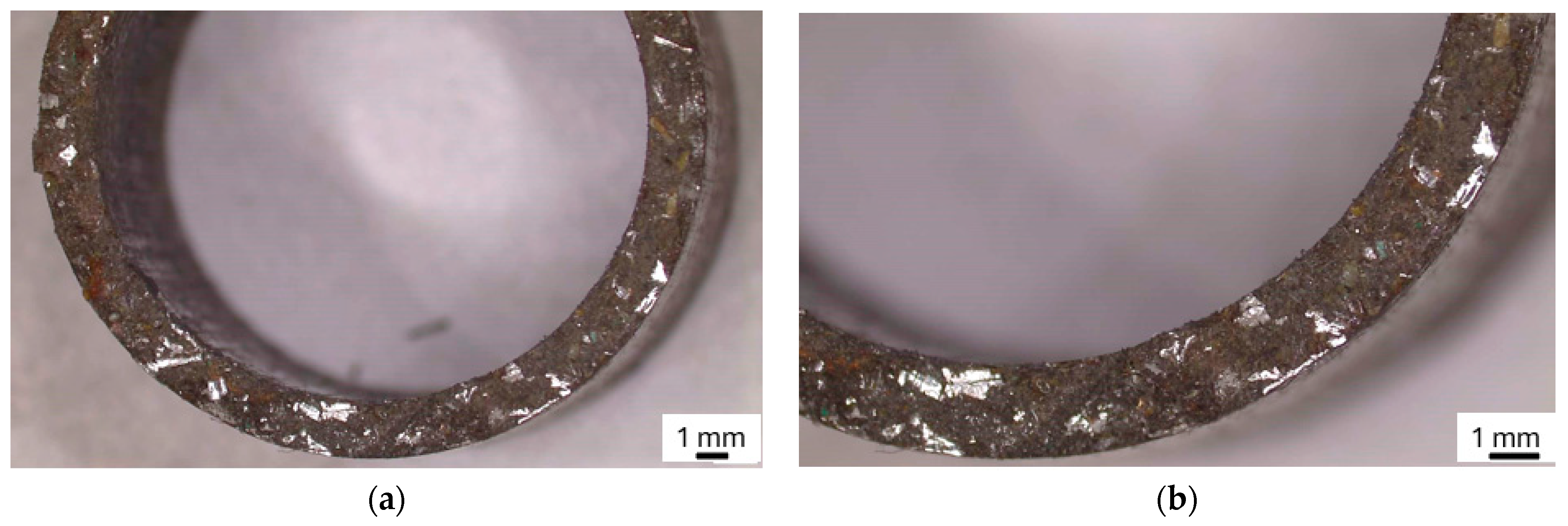
In the end, to further validate the proposed process, it was applied on non-planar geometries. For the first time, this study presents the successful application of direct molding to particulate material shaped into a complex tubular form. As illustrated in
Figure 12, a recycled CFRP tubular ring was fabricated, using an aluminum mold with an internal diameter of 20 mm and an external diameter of 24 mm. The mold was engineered to include a precise clearance between the inner and outer diameters, specifically intended to accommodate a hollow piston. This piston was designed to fit closely within the annular gap and apply uniform pressure to the recycled particulate CFRP, which was strategically distributed in a ring-shaped configuration inside the mold cavity The molding parameters used are the same as the previous molding phase (1.5 bar, 250 °C of the upper hot plate, 220 °C of the lower hot plate for 15 min).
Preliminary visual inspection, combined with stereomicroscopic analysis, highlights a uniform and good degree of compaction across the entire tubular section. As shown in
Figure 13a,b, the cross-section of the recycled CFRP tubular sample exhibits a dense and consistent microstructure, with minimal visible porosity and strong cohesion between the particles. The absence of significant voids or interfacial gaps, particularly at the inner and outer surfaces of the tubular sample, suggests that the applied processing pressure and temperature were sufficient to promote particle rearrangement and thermomechanical reactivation. This level of compaction not only confirms the effectiveness of the selected reprocessing parameters, but also demonstrates that even complex geometries, such as annular sections, can be successfully fabricated via direct molding without the need for extensive preprocessing or additives.
These results validate the potential of this technique for broader application in the recycling of thermoset-based composite powders, also for non-planar components where uniform pressure distribution is more challenging to achieve.
5. Conclusions
Recent advancements in composite manufacturing have shifted toward the development of multifunctional structures that not only maintain excellent mechanical performance but also offer additional properties such as electrical and thermal conductivity, improved damping, reparability, and thermoformability. These multifunctional features are increasingly sought after in aerospace, automotive, and electronic applications where weight, durability, and functionality must be optimized simultaneously. Simultaneously, rising concerns around the environmental impact of composite waste and the global push toward sustainable manufacturing have placed greater emphasis on recycling, reuse, and remanufacturing—key pillars of the circular economy. Among various recycling methods for CFRPs, mechanical recycling and pyrolysis are the only techniques that have progressed to industrial-scale deployment. Mechanical recycling generates large quantities of carbon-rich powders from machining and trimming operations, which are often undervalued or landfilled despite their latent functionality. Recognizing this, the present study proposes a novel and scalable approach to utilize such CFRP machining waste to fabricate composite structures that are not only sustainable but also functionally enhanced. Specifically, we demonstrate the direct compression molding of ground CFRP waste into a rigid core material, which was subsequently integrated with CFRP prepreg skins to form a multifunctional sandwich structure.
For the first time, this recycled material was used to enhance through-thickness electrical conductivity in laminated composites. The compression-molded core—comprising carbon fibers and partially cured thermoset resin fragments—served as both a structural and conductive element. The resulting sandwich panel exhibited improved dimensional stability and structural cohesion, and is, to date, the largest sample successfully manufactured using this method. Electrical characterization confirmed measurable conductivity in both the core-only and sandwich panels, with the latter achieving an average through-thickness conductivity of approximately 0.045 S/cm—more than twice the in-plane conductivity (0.018 S/cm). This enhancement is attributed to the formation of conductive fiber networks across the thickness, promoted by fiber bridging between the skins and the compacted core. While the sandwich panels fabricated in this study demonstrated promising electrical conductivity, the mechanical properties of the sandwich panels, while improved over core-only samples, are currently below typical requirements for structural applications. For semi-structural composites, flexural strengths above 50 MPa and sufficient stiffness are generally needed. Further improvements in interfacial bonding and matrix reactivity are required to meet these mechanical standards for practical use. The lower ultimate strength and brittle failure observed in the current recycled CFRP panels indicate that further optimization—such as improving interfacial bonding and matrix reactivity—is necessary to meet these mechanical thresholds and enable broader practical use. However, despite being performed at laboratory scale, these results demonstrate the effectiveness of using recycled CFRP particles to achieve functional electrical performance. Additionally, dynamic mechanical analysis (DMA) revealed superior viscoelastic performance for the sandwich structure, including a higher storage modulus, elevated glass transition temperature, and enhanced damping behavior compared to the core-alone sample. Mechanical testing further confirmed the benefits of the sandwich design, with failure stresses of 31.6 MPa in the sandwich panel versus 7.6 MPa in the core-only configuration. Although delamination and brittle failure were observed, likely due to weak interfacial bonding and heterogeneous agglomeration, these issues can be mitigated by optimizing the molding parameters or improving residual matrix reactivity. Overall, this work demonstrates the feasibility of repurposing CFRP machining waste into functional, semi-structural composites using a process compatible with existing manufacturing technologies. The approach offers a promising pathway toward high-value applications requiring electrical conductivity, EMI shielding, or lightning strike protection, and establishes a foundation for sustainable, circular material design in advanced composite engineering.

