Review

Electrical Properties of Composite Materials: A Comprehensive Review

by
Thomaz Jacintho Lopes
1,*,†,
Ary Machado de Azevedo
1,†,
Sergio Neves Monteiro
1 and
Fernando Manuel Araujo-Moreira
2
1
Department of Materials Science, Military Institute of Engineering—IME, Praça General Tibúrcio, 80, Urca, Rio de Janeiro 22290-270, Brazil
2
Department of Nuclear Engineering, Military Institute of Engineering—IME, Praça General Tibúrcio, 80, Urca, Rio de Janeiro 22290-270, Brazil
*
Author to whom correspondence should be addressed.
These authors contributed equally to this work.
J. Compos. Sci. 2025, 9(8), 438; https://doi.org/10.3390/jcs9080438
Submission received: 21 April 2025 / Revised: 24 June 2025 / Accepted: 6 August 2025 / Published: 15 August 2025
(This article belongs to the Special Issue Optical–Electric–Magnetic Multifunctional Composite Materials)

Abstract

Conductive composites are a flexible class of engineered materials that combine conductive fillers with an insulating matrix—usually made of ceramic, polymeric, or a hybrid material—to customize a system’s electrical performance. By providing tunable electrical properties in addition to benefits like low density, mechanical flexibility, and processability, these materials are intended to fill the gap between conventional insulators and conductors. The increasing need for advanced technologies, such as energy storage devices, sensors, flexible electronics, and biomedical interfaces, has significantly accelerated their development. The electrical characteristics of composite materials, including metallic, ceramic, polymeric, and nanostructured systems, are thoroughly examined in this review. The impact of various reinforcement phases—such as ceramic fillers, carbon-based nanomaterials, and metallic nanoparticles—on the electrical conductivity and dielectric behavior of composites is highlighted. In addition to conduction models like correlated barrier hopping and Debye relaxation, the study investigates mechanisms like percolation thresholds, interfacial polarization, and electron/hole mobility. Because of the creation of conductive pathways and improved charge transport, developments in nanocomposite engineering, especially with regard to graphene derivatives and silver nanoparticles, have shown notable improvements in electrical performance. This work covers the theoretical underpinnings and physical principles of conductivity and permittivity in composites, as well as experimental approaches, characterization methods (such as SEM, AFM, and impedance spectroscopy), and real-world applications in fields like biomedical devices, sensors, energy storage, and electronics. This review provides important insights for researchers who want to create and modify multifunctional composite materials with improved electrical properties by bridging basic theory with technological applications.

1. Introduction

Because of their superior qualities and adaptability to a wide range of applications, composite materials have become increasingly popular in the fields of materials science and engineering [1]. Electrical characteristics stand out among these attributes because they dictate the efficacy and efficiency of composites in a wide range of technological applications, including sensors, energy systems, and electronic devices [2,3,4]. By carefully choosing and combining their constituent parts, composite materials’ electrical conductivity can be adjusted and optimized, allowing for the development of materials with particular electrical properties, such as fuel cells and batteries [5], that satisfy technological and industrial demands [6].
A review of various combinations of metallic, ceramic, and polymeric matrices [7], as well as the addition of nanoparticles, is necessary for the investigation of the electrical properties of composite materials. The electrical conductivity [8], dielectric permittivity, and thermal stability of the composites [9] can all be greatly impacted by each of these elements. For example, adding metallic nanoparticles to a polymer matrix can significantly increase electrical conductivity, which makes the material a great option for applications where conduction of electricity is essential. Additionally, because of nanoscale effects like enhanced surface area and better phase interfaces that are not seen in conventional composites, nanocomposites can display special electrical properties [10,11].
Continuous technological advancements and the need for more effective and high-performing materials are the main drivers of the need for continued research on the electrical properties of composite materials. Construction materials, energy storage systems, portable electronics, and medical devices can all benefit greatly from advancements in composites [12,13,14].
Figure 1 highlights the technological potential and multidisciplinary relevance of composite materials by illustrating the main research areas in which their electrical properties are being applied. Advanced solutions in a variety of fields have been made possible by conductive composites, which combine electrically active fillers with insulating matrices. The strategic significance of ongoing research and development in electrically functional composite systems is highlighted by this wide range of applications.
In-depth research on the dielectric characteristics of composites can also lead to new opportunities for the development of materials with large charge storage capacities, which are necessary for the production of high-performance energy storage devices like supercapacitors. It will be possible to engineer materials with optimal properties, satisfying the unique needs of different industries and encouraging sustainable and creative technological advancements, if these properties are thoroughly understood. Research on the electrical characteristics of composite materials is therefore not only pertinent but also necessary for ongoing advancement in a number of contemporary technological fields.
According to [15,16], a composite is a material made up of two or more separate phases or components with different physical or chemical properties arranged into a complex architecture at the micro, meso, or macroscopic levels. Metals, ceramics, and polymers are examples of individual materials whose development and use have made it possible to combine them to create synthetic composites. The development of composite materials has enhanced contemporary material systems, aided in the long-term advancement of materials science and engineering, and raised human standards of living.
Advanced composites are a class of materials that can perform better than their individual components [17]. Advanced composites are typically the outcome of structural designs and optimization at different levels and dimensions, frequently incorporating the most recent developments in various material components. Through composition, interface, or dimensional effects at different levels, composites can achieve superior performance or a new functionality that is not possible with a single constituent material. Composite science is based on these basic components [18].
The development of a wide range of materials with property combinations that are not possible for any traditional monolithic materials, such as metallic alloys, ceramics, or polymers, is encouraged by the idea of multiphase composites [19].
The goal of this review is to present a thorough analysis of composite materials’ electrical characteristics, arranged according to the type of reinforcement and matrix used. The basic ideas of electrical conductivity and dielectric behavior in solids are first presented, along with talks about band theory, polarization mechanisms, and charge carrier mobility. The work is then divided into a number of important sections:
  • Metallic composites, in which metallic fillers are used to reinforce polymers and improve conductivity.
  • Ceramic composites, encompassing both dielectric and conductive uses.
  • Polymeric composites, emphasizing both extrinsically and intrinsically conductive polymers.
  • The role of nanomaterials like graphene, carbon nanotubes, and silver nanoparticles is highlighted in nanocomposites.
Every part addresses the structural properties, processing methods, conduction mechanisms, and possible uses for the composite systems under investigation. Moreover, this review emphasizes important results from recent studies, shows experimental data where relevant, and investigates present difficulties and future paths in the evolution of electrically functional composites.
This work advances a better knowledge of how various material systems behave electrically by combining theoretical concepts, experimental evidence, and pragmatic insights, opening the path for creative uses and multidisciplinary research in material science and engineering.

2. Composite Science and Engineering

Generally, scientists and engineers study materials in order to understand each one separately and subsequently search for understanding when two or more materials are combined. Application of structural design depends on knowing the precise link between performance and design. Usually, the most important elements affecting composite materials are research on metals, ceramics, and polymers [20].
Further influencing their structure and properties are the special qualities of composites including their surfaces and interfaces, processing, characterization, performance, and functional principles. For example, whereas functional composites are developed to achieve intermediate properties or entirely new physical/chemical functions compared to the original materials, structural composites are intended to improve mechanical qualities. Structural and functional composites have seen major developments thus far [21].

2.1. Particle Reinforcement

With subclassifications and differentiation according to the reinforcement or strengthening mechanism, this kind of composite is made up of various heterogeneous components. When particle–matrix interactions cannot be handled at the atomic or molecular level, continuum mechanics is employed, as indicated by the term large. The particulate phase is typically stiffer and harder than the matrix in these composites [22].
Because of their capacity to significantly improve thermal and electrical conductivity while preserving their lightweight and structurally sound qualities, particle-reinforced composites have gained significant attention in the field of materials engineering [23,24]. Insulating polymer matrices become multifunctional materials appropriate for demanding environments when conductive fillers like carbon nanotubes, graphene, silver nanoparticles, or metallic particles like copper and aluminum are added [25,26].
The increasing demand for lightweight components with improved thermal and electrical performance in industries like electric vehicles, 5G telecommunications, and renewable energy [27], highlights the strategic significance of these materials. Furthermore, by enabling more energy-efficient devices and lowering raw material usage through enhanced performance, particle-reinforced composites support sustainability goals.
The design space for these composites has increased with the combination of nanotechnology and sophisticated processing techniques, such as additive manufacturing. Still, there are a number of obstacles to overcome, such as the requirement for better particle dispersion, more robust interfacial bonding, and scalable, economical production methods. To fully utilize the potential of these advanced materials, these issues must be addressed through targeted research [28,29].

2.1.1. Large Particle Composites

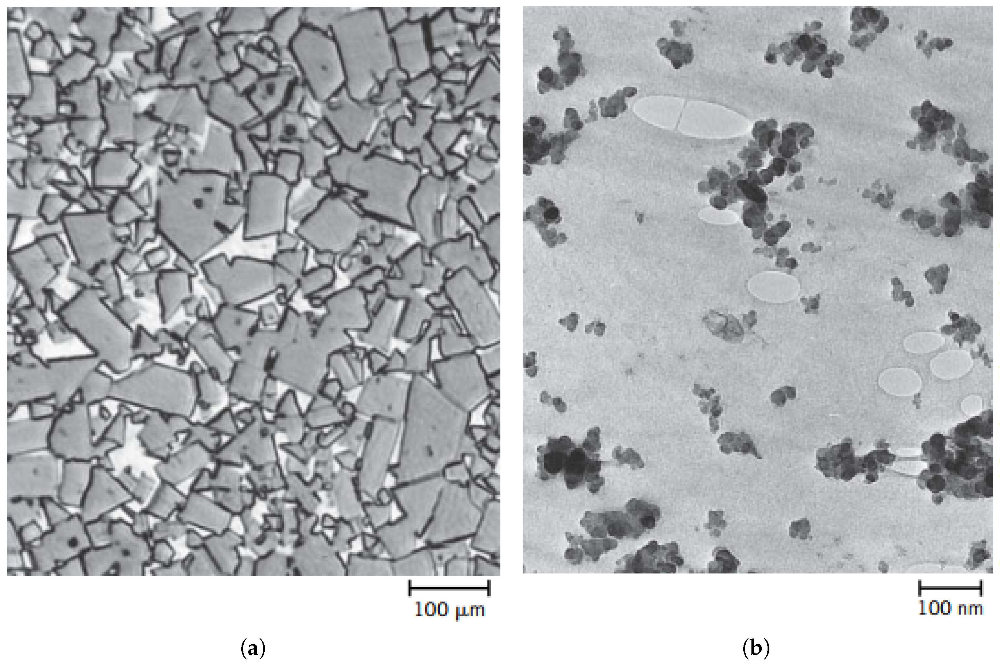
This composite category includes a variety of materials, the most well-known of which is concrete, which is mainly made up of cement, sand, and gravel. Although the particles have different geometries, it is important that they are roughly equal in size in all directions (equiaxed). Large-particle composites are used in all three material categories (metals, polymers, and ceramics), and it is noteworthy that the volume fraction has a substantial impact on the mechanical properties. Figure 2 depicts a synthetic rubber matrix with spherical carbon particles and large reinforcement particles in a cobalt (Co) matrix.

2.1.2. Dispersion-Strengthened Composites

Fine particles of an extremely hard and inert material can be uniformly dispersed to strengthen and harden metals and metal alloys. These scattered particles are frequently made of oxide materials and can be either metallic or non-metallic. The strengthening mechanism entails particle–particle interactions and matrix dislocations, much like the precipitation-hardening process. Because the dispersed particles are chosen to prevent reactions with the matrix, the reinforcement that dispersion provides is maintained even at high temperatures and over long periods of time, even though it may not be as noticeable as in precipitation hardening. Because precipitates grow or dissolve after heat treatment, strength enhancement in precipitation-hardened alloys may be reduced [30].

2.2. Fiber-Reinforced Composites

The efficiency of the load transfer from the fibers to the matrix affects the mechanical properties of a fiber-reinforced composite in addition to the fiber’s characteristics [31]. The strength of the bond between the fiber and matrix phases is a critical component of this load transfer [32]. This fiber–matrix bond is broken at the fiber ends when stress is applied, which causes the matrix to deform. Stated differently, the various reinforcement types within a matrix are presented without any load transfer from the matrix at each fiber end.
Polymeric, metallic, ceramic matrices, carbon-reinforced carbon fibers, and hybrids are among the different types of fiber-reinforced composite materials [33]. When fibers are added to each type of matrix, they may acquire new properties that make them individually more appropriate for particular applications [34].

2.3. Structural Composites

Multiple layers make up a structural composite, which typically has a low density. It is used in applications that demand structural integrity and is frequently distinguished by high stiffness, tensile, compressive, and torsional strength. Their properties are derived from the geometry of the structural elements’ design as well as the properties of the component materials. Two prominent examples of structural composites are sandwich panels and laminated composites [35].

2.3.1. Laminated Composites

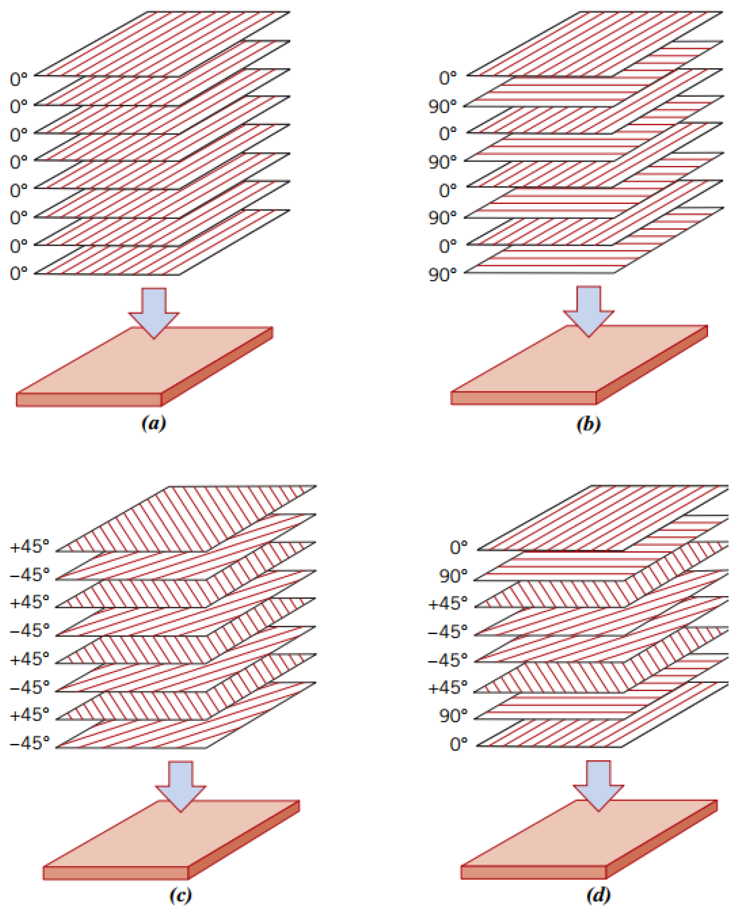
Sheets or bidimensional panels, sometimes referred to as layers or laminates, are joined to form a laminated composite. As demonstrated by polymers reinforced with continuously aligned fibers, each layer has a preferred direction of strength [36]. Figure 3 displays laminated composite models.
It is important to remember that the reinforcement’s size and orientation have an impact on these composite materials’ physical characteristics as well, including how the high-strength direction varies from layer to layer. Laminated composites fall into four categories: unidirectional, angle-ply, cross-ply, and multidirectional. All layers in unidirectional laminates have the same high-strength direction orientation. Various orientations of laminated composite layers are depicted in Figure 4.

2.3.2. Sandwich Panels

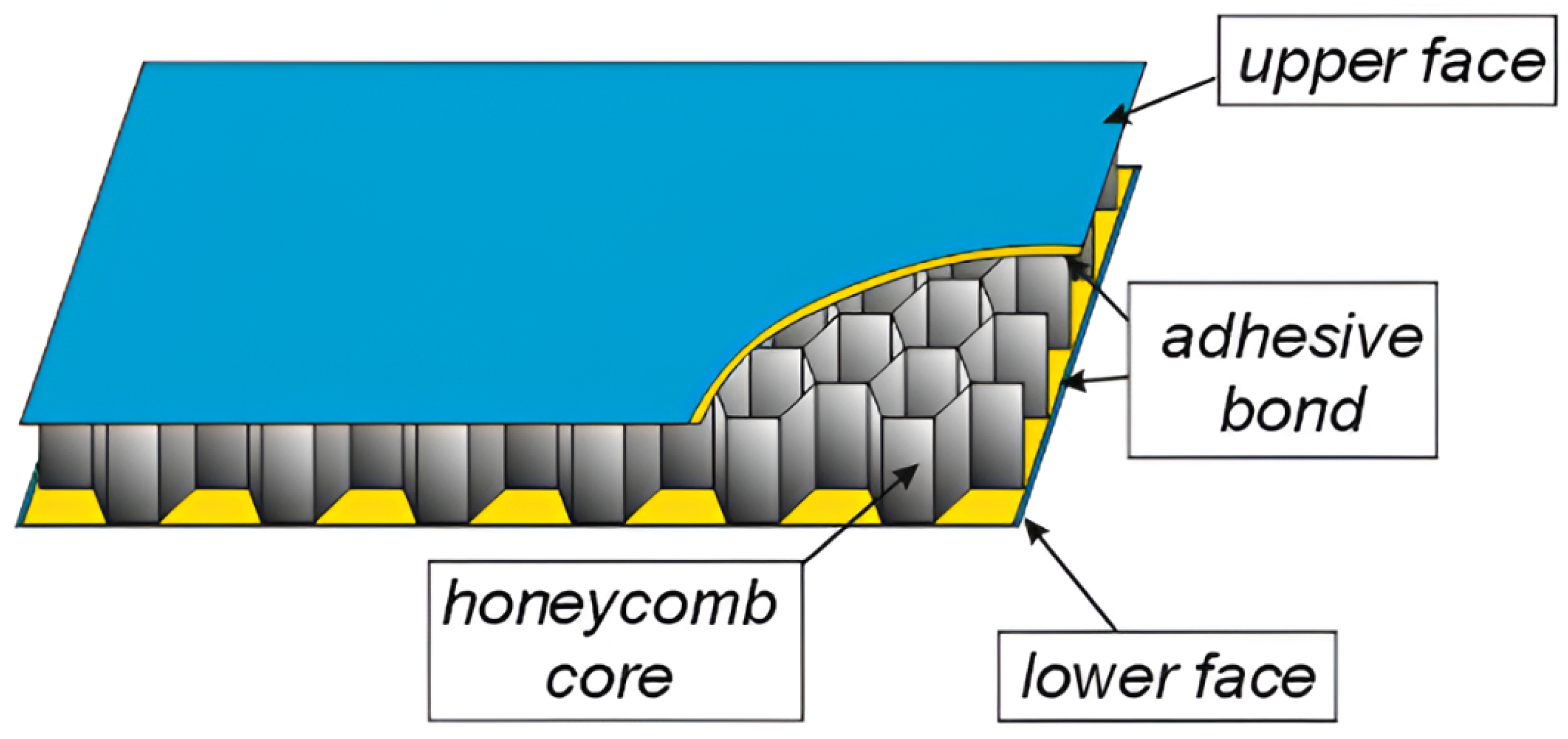
A thin laminated composite and a sandwich model combine to create a shell structure made up of several layers joined by adhesives. A lightweight core and two thin outer faces—which may be composed of laminated or isotropic panels—make up a typical sandwich structure. The lightweight core’s main feature is its low weight; it cannot sustain large forces. The contribution of light loads is significantly increased and reinforcement is not required when the core is constructed as a composite. As seen in Figure 5, the cores are frequently just empty spaces that produce porous or foam cores. Building the core as a three-dimensional structure, like corrugated panels or spatial truss structures composed of beams or plates, is an additional option [38].

2.3.3. Nanocomposites

Materials that are composed of several phases and have at least one, two, or even three dimensions at the nanoscale are known as nanocomposite materials. These materials usually have structural features that are smaller than 100 nanometers (nm), which is the standard threshold used in materials science to define the nanoscale. Phase interfaces are formed when material dimensions are reduced to the nanometric level, and these interfaces are essential for improving the material’s properties [39].
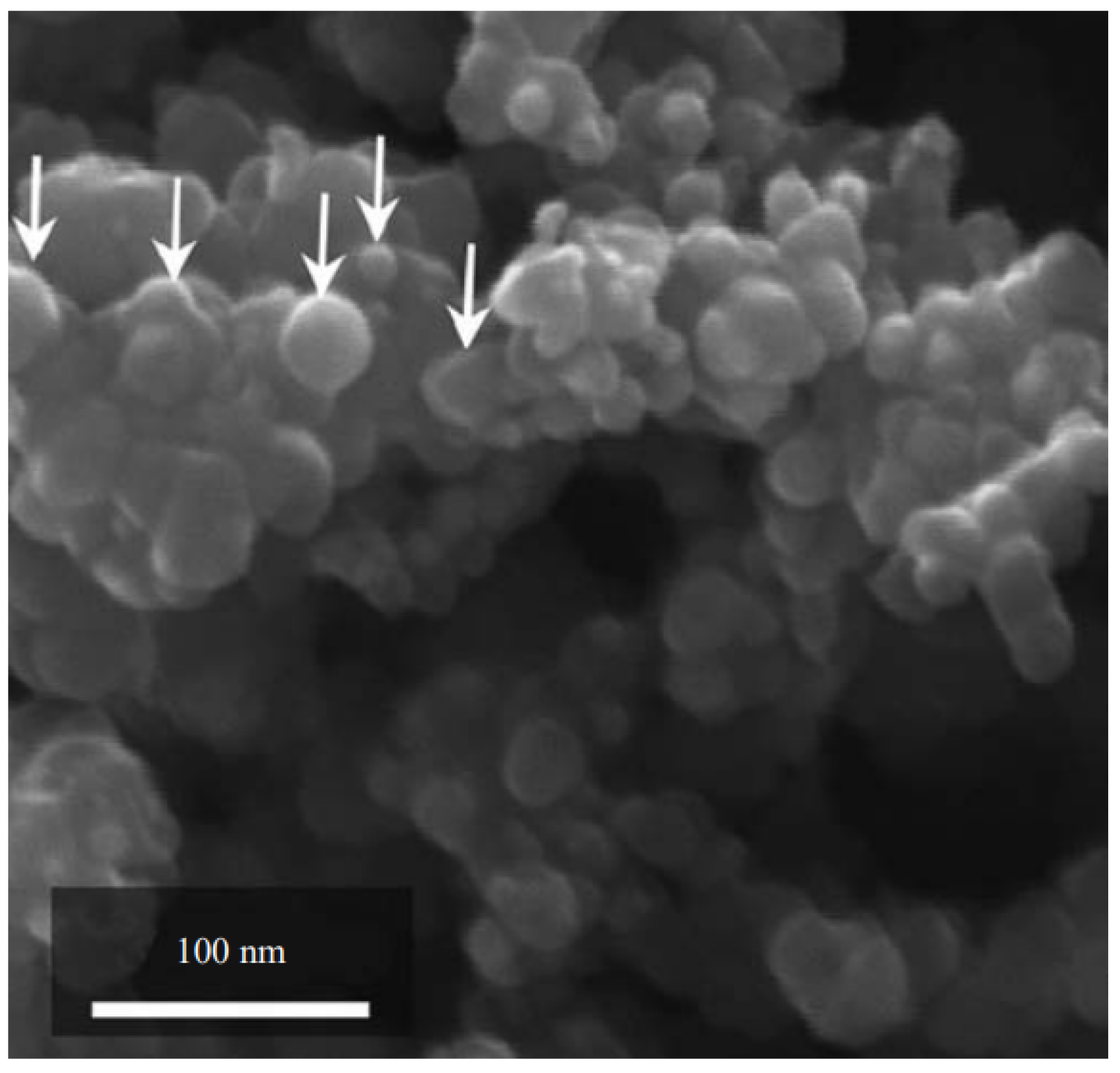
Understanding the structure-property relationship is closely tied to the volume and surface area of the reinforced material used to prepare nanocomposites. When compared to traditional filler materials, nanocomposites can be designed to have better mechanical, electrical, magnetic, optical, thermal, biological, and transport properties [40]. Furthermore, these characteristics can be modified to suit particular uses [41]. Because of these factors, nanocomposites are being used in many contemporary technologies [30]. An SEM (Scanning Electron Microscope) image of a SiC (Silicon Carbide) sample is displayed in Figure 6.

3. Electrical Properties

A common idea is that the electron is a tiny particle connected to electricity. According to Solymar (2014) [43], this perception is largely unaffected by the study of electromagnetism. The notion of studying the atom ( α τ o μ o = indivisible) was first proposed in Greece thousands of years ago, and although it has undergone historical ups and downs, its validity is now acknowledged by all. Since matter is made up of atoms, it makes sense to assume that they are arranged in some way, overlapping one another.
Crystallography is the scientific field that studies how atoms are arranged in space. According to this chapter, all materials crystallize in a basic cubic structure, like the one shown in Figure 7, with some free electrons roaming among the lattice ions and the lattice ions fixed (like in a solid) [44].
The existence of a corresponding amount of positive charge in the solid must be acknowledged when taking into account the presence of a specific number of electrons that are able to conduct electricity. The solid must therefore appear to the outside world to be electrically neutral. Moreover, it is reasonable to assume that electrons travel through the gaps between the lattice atoms and occasionally run into them. An extension of this analogy would be to say that, at equilibrium, electrons have a configuration that is highly dependent on the system’s temperature and follow a statistical distribution akin to that of gas molecules.

3.1. Ohm’s Law and Conductivity

Given a potential difference U applied at the ends of two solids of length L, the electric field is defined as
E = U L [ V / m ]
This field generates acceleration in the particles:
a = e m E [ m / s 2 ]
Electrons acquire velocity in the direction of the electric field in addition to their random velocities. Considering the mass difference between the electron and the lattice atoms, it can be assumed that this directed velocity is entirely lost following each collision. As a result, only the portion of this velocity that is recovered in between collisions matters [43].
The average velocity of each electron is given by
ν m é d i o = a τ [ m / s ]
where τ is known as the mean free time, i.e., the average time during which no collision occurs between the electron and the lattice particles.
The drift velocity can be related to the electric field as
ν D = e m τ E [ m / s ]
where the term e m τ represents the electron mobility.
Given an electron density ( N e ) passing through a cross-sectional area with drift velocity, the current density can be expressed as
J = N e e ν D [ A / m 2 ]
Substituting Equation (4) into Equation (5), the relation for Ohm’s First Law [45,46] in terms of current density is obtained:
J = σ E [ A / m 2 ]
where σ is the electrical conductivity of the material S / m .
It is worth noting that the material’s resistivity is inversely proportional to its electrical conductivity, i.e.,
ρ 1 σ [ Ω · m ]
Resistivity ( ρ ) can also be obtained through
ρ = R A l [ Ω · m ]
The basic connections between electric and magnetic fields, as well as how electric charges and currents affect them, are explained by Maxwell’s equations. They are expressed in a differential form as follows:
· E = ρ ε 0 [ V / m 2 ]
This is Gauss’s Law for Electricity, which states that the divergence of the electric field E is proportional to the charge density ρ , where ε 0 is the vacuum permittivity F / m .
· B = 0 [ T / m ]
This is Gauss’s Law for Magnetism, which states that magnetic monopoles do not exist; the magnetic field B has no divergence.
× E = B t [ V / m 2 ]
The relationship between a time-varying magnetic field and the induced electric field is known as Faraday’s Law of Induction.
× B = μ 0 J + μ 0 ε 0 E t [ T / m ]
This is the Ampère–Maxwell Law, which states that magnetic fields are generated both by electric currents J and by time-varying electric fields E t . Here, μ 0 is the vacuum permeability [ H / m or N / A 2 ] .

3.2. Energy Bands in Solids

It is possible to assume that every electron in a crystalline solid essentially moves independently in a static periodic potential field for a variety of purposes. It is assumed that the selection of this field considers the average interaction between the electron in focus and the rest of the crystal. The band theory of solids is based on this perspective. This theory has offered a useful conceptual framework for both qualitative and quantitative discussions of the electronic properties of crystals because of its intrinsic simplicity and intuitive appeal [47].
At present, it is known that many of the electrical, magnetic, optical, thermal, and elastic properties of crystals depend on a thorough understanding of their band structure, which can be highly complex. This explains why studying band structures has recently attracted a lot of theoretical and experimental attention.
Electronic conduction is the primary mechanism of electrical conduction in conductors, semiconductors, and a variety of insulating materials [48]. The number of electrons available for this process has a significant impact on the electrical conductivity’s magnitude [49]. The various material kinds and their electrical properties in relation to their layers are depicted in Figure 8.
But, when exposed to an electric field, not every atom’s electron moves. The arrangement of the electrons’ states or energy levels and the way these states are filled determine how many electrons can conduct in a given material [50,51].
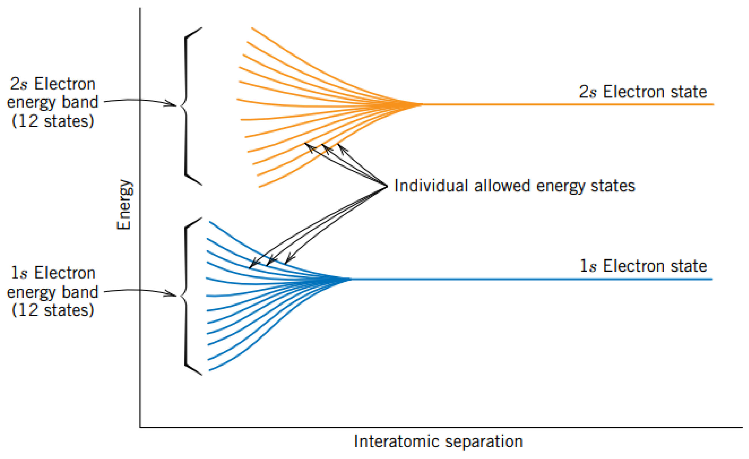
Therefore, the general understanding of electronic behavior depends on the sublevels in each material’s atomic structure where electrons are arranged. Electrons can fill the layers (1, 2, 3, …) and sublevels (s, p, d, and f) of each atom by occupying its energy level [30]. The electron energy bands whose dependence is linked to the interatomic separation are depicted in Figure 9 [52].
Consequently, the free electron model and the periodic lattice of the crystal must be examined in order to comprehend the distinction between insulators and conductors. The band gap is a new property that results from this. It is made up of areas where certain energy levels are inaccessible to electrons. It should also be noted that it is the outcome of the interaction between the ions of the crystalline lattice and waves related to conduction electrons [44].

3.3. Electron Mobility

Free electrons experience a force when an electric field is applied, and because of their negative charge, they accelerate in the opposite direction of the applied electric field. The accelerated electron and the atoms of a perfect crystalline lattice do not interact, according to quantum mechanics. Free electrons should accelerate along the electric field in these circumstances, creating an electric current that gradually grows. But, as soon as a field is applied, current is known to reach a constant value, indicating the presence of resistive forces that offset this external field acceleration.
Electron scattering from crystalline lattice defects, such as impurities, vacancies, interstitial atoms, and thermal vibrations between lattice atoms, produces these resistive forces, also known as frictional forces. Resistance to the flow of electric current is a manifestation of the electron scattering phenomenon. Parameters like electron mobility ( μ e ) and drift velocity ( v d ) under an applied electric field ( E ) are used to characterize this scattering behavior. The following equation can be used to express this behavior:
v d = μ e · E [ m / s ]
Additionally, the conductivity of most materials can be defined by
σ = n | e | μ e
where n is the number of free electrons, and | e | is the magnitude of the electric charge.

3.4. Dielectric Properties

Because dielectric materials can electrically insulate and store energy when exposed to electric fields, they are essential in electrical and electronic engineering [53,54]. Despite not conducting electricity, these substances—also referred to as insulators—have the capacity to store electrical energy as an internal electric field [55].
Among dielectric materials properties are their essential function in electrical insulation, which stops electric current flow and guards against electric shocks. These materials are crucial for capacitor operation because they can also internally store electrical energy [56].
A number of variables influence the characteristics of dielectric materials, including the dielectric constant ( ε ), which gauges the material’s capacity to retain electrical energy. The storage capacity increases with the value of ε . Polarization, or the displacement of electric charges in reaction to an external electric field, is another important characteristic. Additionally, dielectric materials have dielectric strength and magnetic permeability ( μ ), which establish the highest voltage that the material can tolerate before turning conductive [57].
Solids (polymeric, ceramic), liquids (mineral oil, deionized water), and gases (dry air, nitrogen) are the different categories of dielectric materials. Temperature, crystal structure, chemical composition, and the frequency of the applied electric field all affect their characteristics [58].
Dielectric materials have found innovative uses in microwave ovens, transformers, high-voltage cables, antennas, sensors, and capacitors [56]. Developing customized dielectric materials, investigating recyclable or biodegradable alternatives, and applying nanotechnology to produce new dielectrics with improved qualities are some of the challenges and viewpoints of the future.

Electrophysical Characteristics of Dielectrics

When exposed to external electric fields, dielectric materials show significant electric behavior despite being insulators. Their electrophysical characteristics are characterized by two basic quantities: polarization and permittivity.
The following formula provides the electric displacement field D in a dielectric material:
D = ε 0 E + P [ C / m 2 ]
Here, D represents the electric displacement field [C/m2], E represents the electric field [V/m], ε 0 represents the vacuum permittivity F / m , and P represents the polarization vector [C/m2], which represents the electric dipole moment per unit volume.
The polarization of linear, isotropic dielectrics is proportional to the applied electric field:
P = ε 0 χ e E [ C / m 2 ]
where χ e is the dimensionless electric susceptibility, which measures the ease of polarization of a dielectric. The total permittivity ε of a material is related to the vacuum permittivity by the relative permittivity ε r (which is also dimensionless):
ε = ε r ε 0 [ F / m ]
Substituting into the displacement field, we obtain
D = ε E [ C / m 2 ]
Understanding these relationships is essential for comprehending the behavior of dielectrics in high-frequency electronic applications, insulating systems, and capacitors.

3.5. Semiconductivity

Compared to metals, semiconductors have lower electrical conductivity. The band diagram for various material types is displayed in Figure 10. Nevertheless, they exhibit distinctive qualities that render them beneficial for a range of uses. Even very small impurity concentrations have a significant impact on these materials’ electrical characteristics. Two types of semiconductors are (i) intrinsic and (ii) extrinsic [49].
When the intrinsic electronic structure of the pure material dictates the electrical behavior, the semiconductor is said to be intrinsic. The semiconductor is said to be extrinsic when impurity atoms affect its electrical characteristics.

3.5.1. Intrinsic

Because the intrinsic electronic structure of the pure material dictates its electrical behavior, intrinsic semiconductors are categorized in this manner. They are distinguished by a filled valence band that is isolated from the empty conduction band by a forbidden band, usually with an energy differential of less than 2 eV [30]. With forbidden band gaps of roughly 1.1 eV and 0.7 eV, respectively, silicon (Si) and germanium (Ge) are the most fundamental elemental semiconductors. Additionally, compounds that are typically formed from elements in Groups IIIA and VA of the periodic table can exhibit intrinsic semiconductor behavior [59].
Intrinsic semiconductors have an empty electronic state in the valence band when an electron is excited to the conduction band, which causes an electron in one of the covalent bonds to disappear. Because other valence electrons are constantly filling the incomplete bond, the position of this absent electron in the crystalline lattice can be thought of as moving when an electric field is present. Treating the missing electron in the valence band as a positively charged particle, known as a “hole,” makes this process easier to understand intuitively [30].

3.5.2. Extrinsic

The conductivities, σ , of silicon and germanium samples are generally substantially higher than the previously stated values. This happens because the σ in semiconductors is very sensitive to impurity presence. Conductivities can vary hundreds of times between two samples of the same semiconductor material with varying impurity levels, even at concentrations so low that they are undetectable by traditional chemical analysis. Because of this, semiconductor technology plays a crucial role in measuring and managing impurity concentrations.
Semiconductors are made through the doping process from materials that are initially very pure, usually having total impurity levels of roughly 10 7 %. In other words, there is inadvertently one impurity atom for every 10 9 atoms of the material [30].

4. Electrical Properties of Composite Materials

Using the most pertinent studies and research on the topic, this chapter attempts to present the electrical properties of composite materials. It is crucial to remember that composites have unique mechanical, electrical, thermal, and optical qualities. Some of the most important electrical properties will be covered in order to make the presented manuscript easier to read. The composites and their primary uses are compiled in Table 1.
Highlighting practical uses of the aforementioned composites is the goal of each section. It is important to remember that every topic offers essential features for comprehending the subject practically, as well as its scholarly and experimental uses.
The idea of composite materials and their uses has existed since antiquity, as was covered in earlier chapters. Chung in 2002 [68] discusses the multifunctionality and applications of composite materials for various subclassifications in order to summarize the subject and highlight its potential. In 2003, Kumar and Fellner [69] provided an overview of proton-conducting polymer–ceramic composites that were developing in relation to their potential use as fuel cell membrane materials.
A bibliographic review of the physical characteristics of polymeric composite materials, including their electrical behavior, was carried out in 2018 by Kashfipour et al. [70]. Highlighted are changes to polymer chains brought about by the addition of nanoparticles.
Energy storage is one of the many potential uses for composite materials that has grown in popularity recently. When talking about the electrical characteristics of composite materials for building supercapacitors in 2021, Yadav and Sharma [71] underlined the importance of being aware of energy demands. Similar research on nanocelluloses was carried out by Xiao et al. [72].
Composite materials have developed in tandem with the increasing research on sensors for disease and pest control brought on by the COVID-19 pandemic. Khan, Akbar, and Yoon [73] studied the electrical characteristics of composite materials used in biological sensors in 2022.
Because of the various demands of contemporary society, research on the electrical characteristics of composite materials is still important. They were once mainly researched for armament fortification, but today they are used in every industry.

4.1. Metallic Composites

Metal-reinforced polymer composites are conductive polymers that were originally insulating materials that have been altered with metallic fillers. These composites, in contrast to polymers with inherent conductivity, find use in a wide range of fields, such as aerospace, construction, military hardware, and electrical circuit engineering. They are frequently utilized as semiconductors [74], dielectric materials [75], construction panels, ballistic protection [76,77], and aircraft materials [78]. These composites are notable for their low weight, good physical qualities, and intermediate electrical and thermal conductivity. They also provide high specific strength, high specific modulus, and fatigue and corrosion resistance.
The most desired characteristic of metal-reinforced polymer composites is electrical conductivity, which is inextricably linked to the metallic particles that were used to prepare them. The composite’s electrical conductivity can be expressed as either conductivity or resistivity. According to studies, conductivity rises as the amount of metallic filler increases, peaking at the highest filler content. The highest electrical conductivity values for these composites are shown in Table 2 [79].
Because of its high elasticity, extreme softness, high electrical conductivity, and mechanical–electrical decoupling, the liquid metal–elastomer composite is a promising conductive alternative for bioelectronics applications, including skin interfaces, flexible robots, and other devices [87,88].
Additionally, certain composites have higher elasticity, comparable to that of tissues, high breathability, stable high electrical conductivity even under deformation, and compatibility with magnetic resonance imaging. By lowering percolation thresholds and minimizing leakage through moisture effects, porous structures help reduce the use of highly toxic liquid metals.
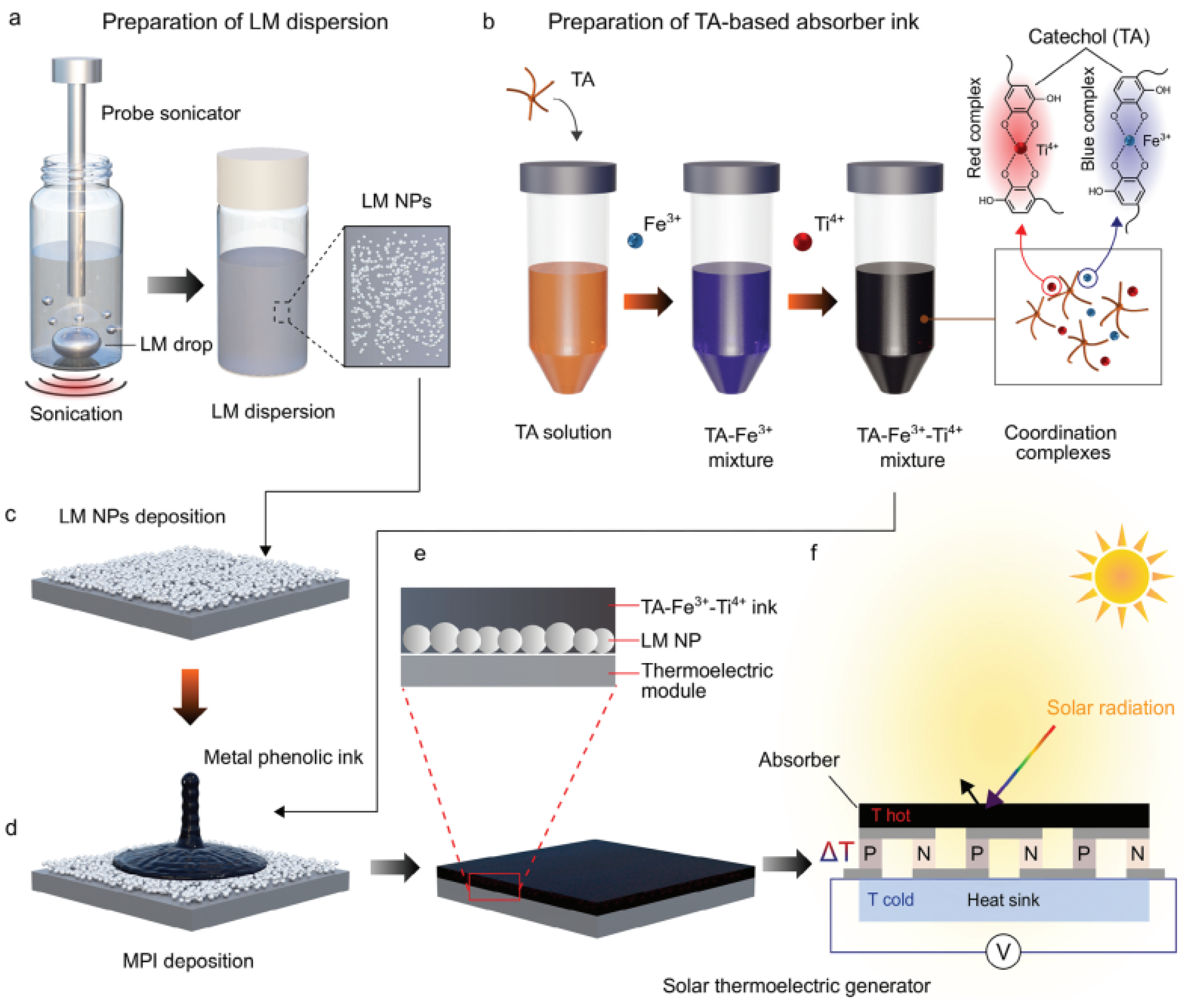
One major obstacle in the quest for clean energy production is the creation of sophisticated solar energy technologies that effectively transform solar radiation into heat and subsequently electricity. As a result, a photothermal absorber made of liquid gallium particles and a polyphenol-based natural coordination ink must be designed. The design of this composite can be applied to flexible substrates and utilizes the adjustable light absorption properties of polyphenol inks [89].
The processing and construction of a photothermal screen using liquid metal to capture solar radiation for energy conversion is schematically depicted in Figure 11.
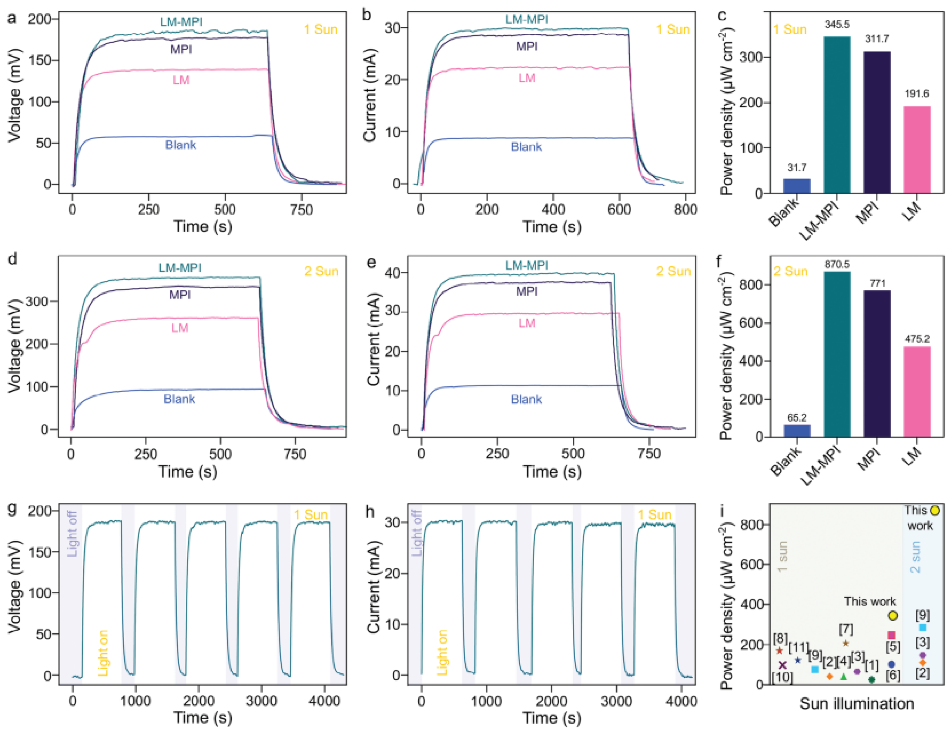
Even though the ink absorbs light at different wavelengths using two different coordination complex types, the thermoelectric effect is increased by the gallium liquid particles’ strong thermal and electrical characteristics. As a result, the photothermal composite has very effective solar-to-heat conversion and broad-spectrum light absorption. When exposed to sunlight, a thermoelectric generator coated with the photothermal composite exhibits an impressive voltage output of ≈185.3 mV without the need for optical concentration, setting a new record for a power density of 345.5 μ W cm−2 [90,91,92].
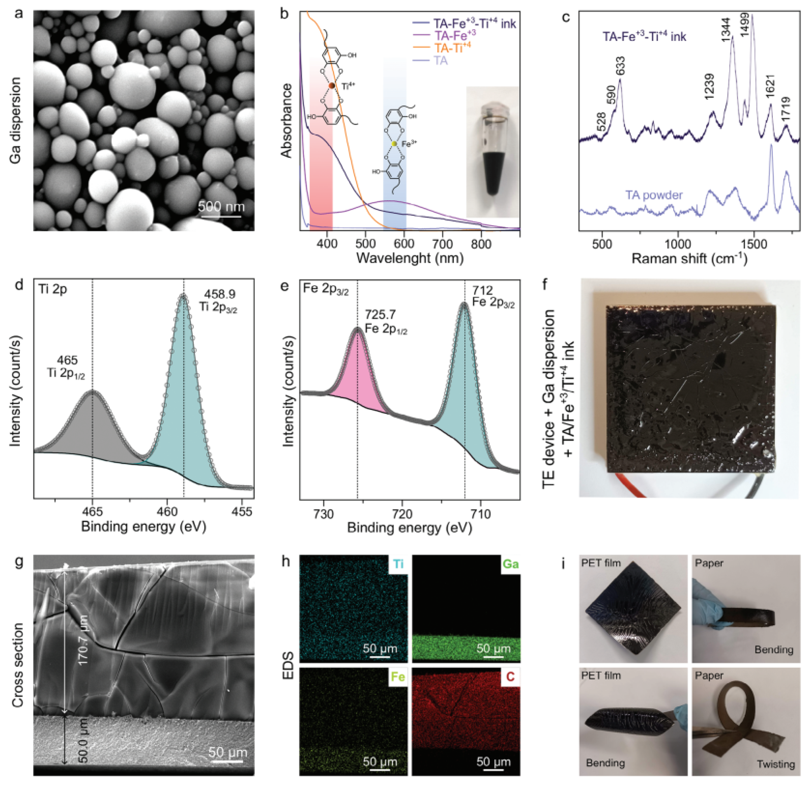
Following production, the samples undergo the necessary characterizations to assess their structure, composition, and particle arrangement, as illustrated in Figure 12.
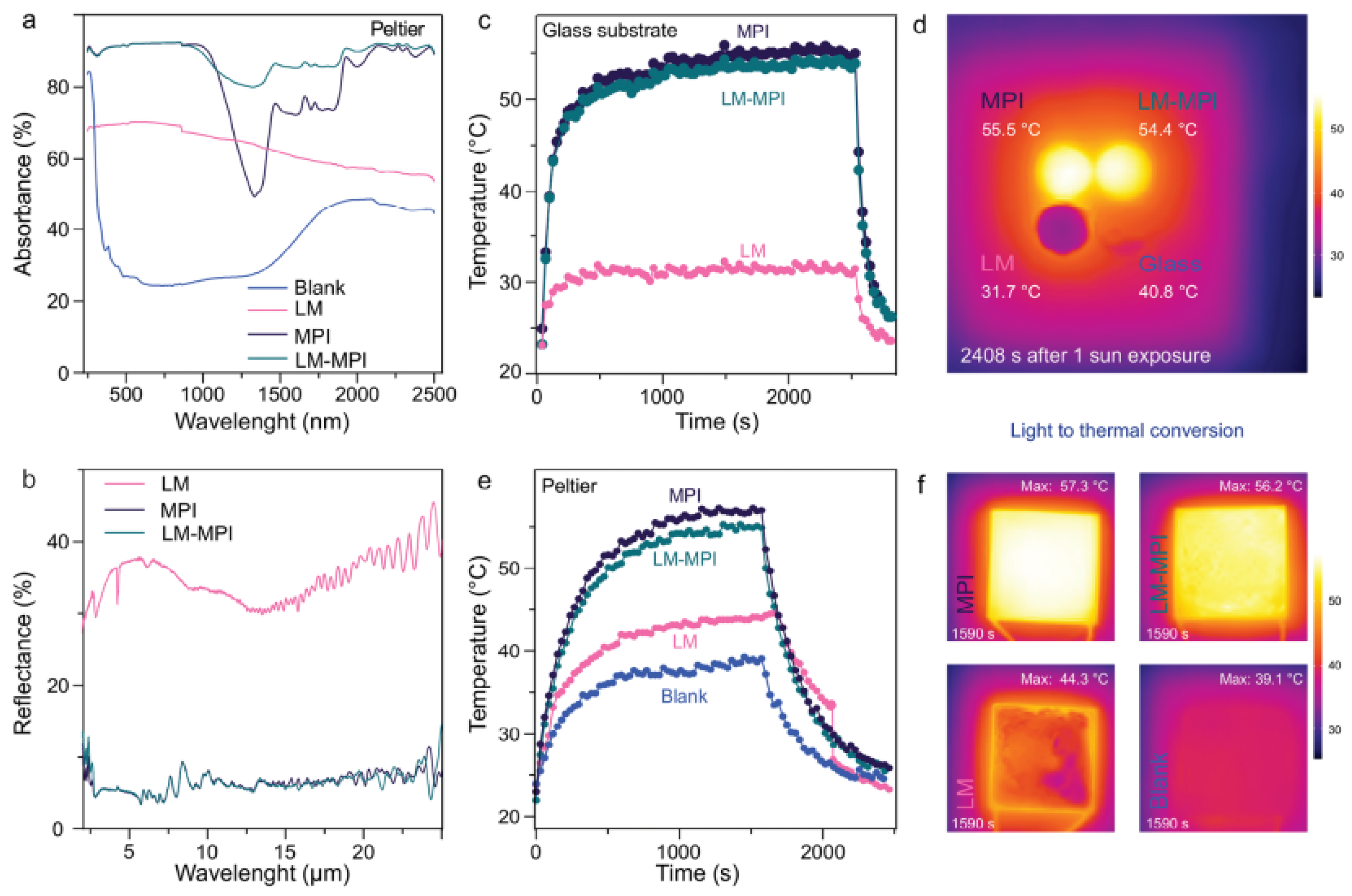
To evaluate the conversion capability of this composite, it is essential to perform FTIR characterization to verify how temperature influences absorbance. Figure 13 presents the behavior of the temperature gradient due to solar radiation on the composite materials.
An essential prerequisite for the effective thermoelectric energy conversion in TE devices is a temperature differential, also referred to as a thermal gradient. The voltage produced increases with the temperature differential between the device’s hot and cold sides [93,94]. Consequently, a TE device’s photothermal performance was assessed. Under solar irradiation, LM-MPI and MPI can achieve efficient light-to-heat conversion with a uniform temperature distribution. The results of the electrical conversion behavior of liquid metal composites under solar irradiation are displayed in Figure 14. Given the significant yield and energy conversion, it is observed that their application is feasible.

4.2. Ceramic Composites

In many applications, ceramic materials are essential, particularly when it comes to electrical properties [95]. Their distinct qualities, along with composites’ adaptability, create a plethora of opportunities for creative applications in various industries.
Numerous applications for ceramics are being investigated. Capacitors, which store electrical energy in electronic circuits, are made of materials like porcelain and barium titanate. Current flow is managed by resistors, which are composed of silicon nitride and zinc oxide. Filters block unwanted frequencies in electronic signals by using the dielectric and piezoelectric properties of alumina and zirconium [96,97].

4.2.1. Conductivity

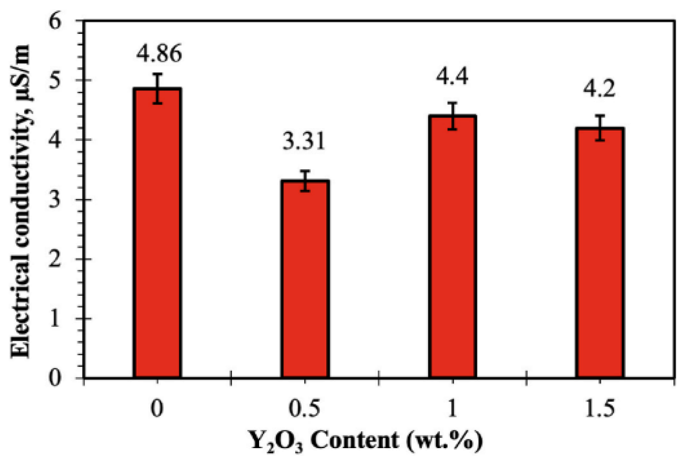
Electronic devices, heat sinks, and turbines that function in high-temperature environments require materials with high thermal conductivity [98]. Despite difficulties when used with semiconductors because of differences in thermal expansion coefficients, copper (Cu) is favored for its superior thermal and electrical conductivity, which makes it a perfect choice for effective heat sinks [99,100,101,102]. On the other hand, mechanical and electrical properties change when additional components are added. For instance, a copper matrix reinforced with Y 2 O 3 reduces the conductivity of the composite. The effects of the oxide reinforcement on the matrix are displayed in Figure 15.
According to the study, the electrical conductivity of the composites dropped when 0.5% by weight of Y 2 O 3 was added, but it then sharply increased when 1% and 1.5% by weight of Y 2 O 3 were added. The presence of Y 2 O 3 ceramic particles at the grain boundaries, which obstruct electron movement in the copper conductive matrix, is responsible for the initial decrease in conductivity with 0.5% of Y 2 O 3 [103]. Furthermore, the lack of electrical conductivity in Y 2 O 3 itself slows down the movement of electrons. Higher porosity and agglomeration effects are probably the cause of the conductivity decrease with 0.5% of Y 2 O 3 .
Despite the higher reinforcement content, the subsequent increase in conductivity with 1% and 1.5% of Y 2 O 3 suggests the influence of other factors. Samples containing 1% and 1.5% of Y 2 O 3 exhibited lower porosity and higher density, which probably allowed for a more uniform distribution and less agglomeration of the Y 2 O 3 particles, minimizing disruption of electron flow. Consequently, even though the addition of Y 2 O 3 reduces conductivity when compared to pure Cu, the increase in density and distribution at 1% of Y 2 O 3 allowed for higher conductivity between the composites, making it a suitable composition for thermal and electronic applications.
The creation of novel battery substitutes is another crucial field of study. Nowadays, many industries, including consumer electronics, grid energy, and transportation, place a high priority on improving the quality and safety of lithium-ion cells. The creation of novel solid lithium-ion conductors, which are intended to take the place of the liquid electrolytes currently employed in lithium-ion cells, can satisfy this need.
Because solid electrolytes are typically less toxic and flammable than liquid ones, this substitution is beneficial not only for safety reasons but also because it makes packaging easier. Dead weight can be greatly decreased by producing each component of the cell as thin films.
However, before a candidate solid electrolyte can be used in lithium-ion batteries, a number of requirements must be fulfilled. High ionic conductivity—above 10 4 S/cm at room temperature—with very little electronic conductivity is the most important factor. A broad electrochemical window is also necessary. Lastly, the solid electrolyte needs to be mechanically, chemically, and thermally stable [104,105,106,107,108].
Two material groups have so far surfaced and are being considered for use as solid electrolytes: glasses based on L i 2 S and compounds based on oxide. The commercialization of L i 2 S -based glasses is hindered by their poor chemical stability against moisture and difficult preparation, despite their excellent ionic conductivity. Table 3 lists additional groups that are being investigated for possible solid electrolyte applications. These groups include different oxide-based lithium-ion conductors.
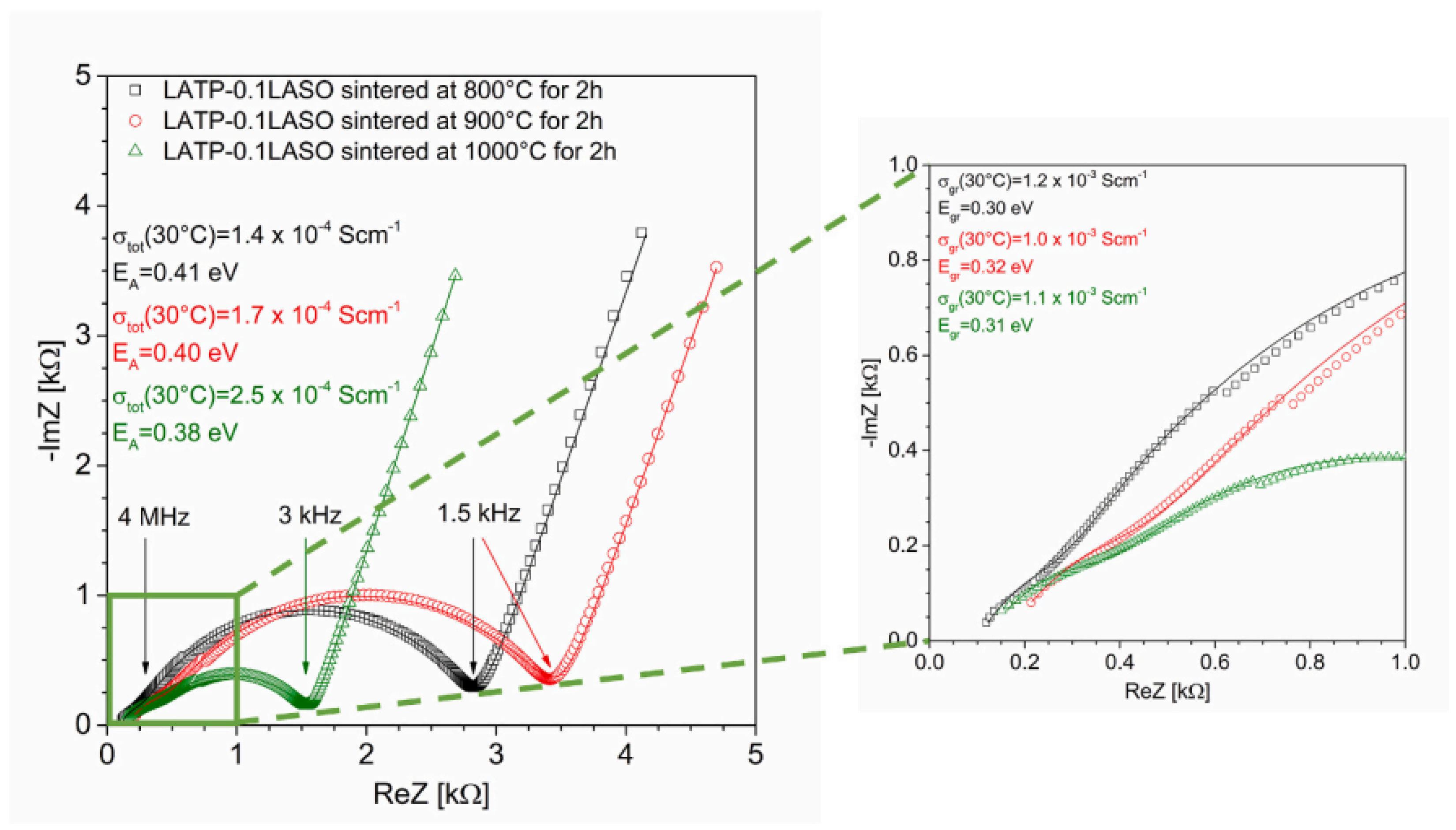
As seen in Figure 16, the ionic conductivity rises in samples sintered at 900 °C and 1000 °C but falls in samples sintered at 800 °C. The microstructural alterations brought about by sintering were responsible for the electrical conductivity values; higher temperatures enhanced the cohesion between the grains. The samples that were sintered at 800 °C exhibit insufficient sintering.
The spectra’s analysis shows that the low frequency represents the grain boundaries, while the high frequency represents the grain’s interior. Nyquist plots were used to calculate the total resistances and grain resistances [104]. This technique involves the analysis of the open-loop response to evaluate the stability characteristics of closed-loop systems. The ionic conductivities were calculated based on impedance spectra acquired over a range of frequencies, with the values derived from the corresponding impedance plots.
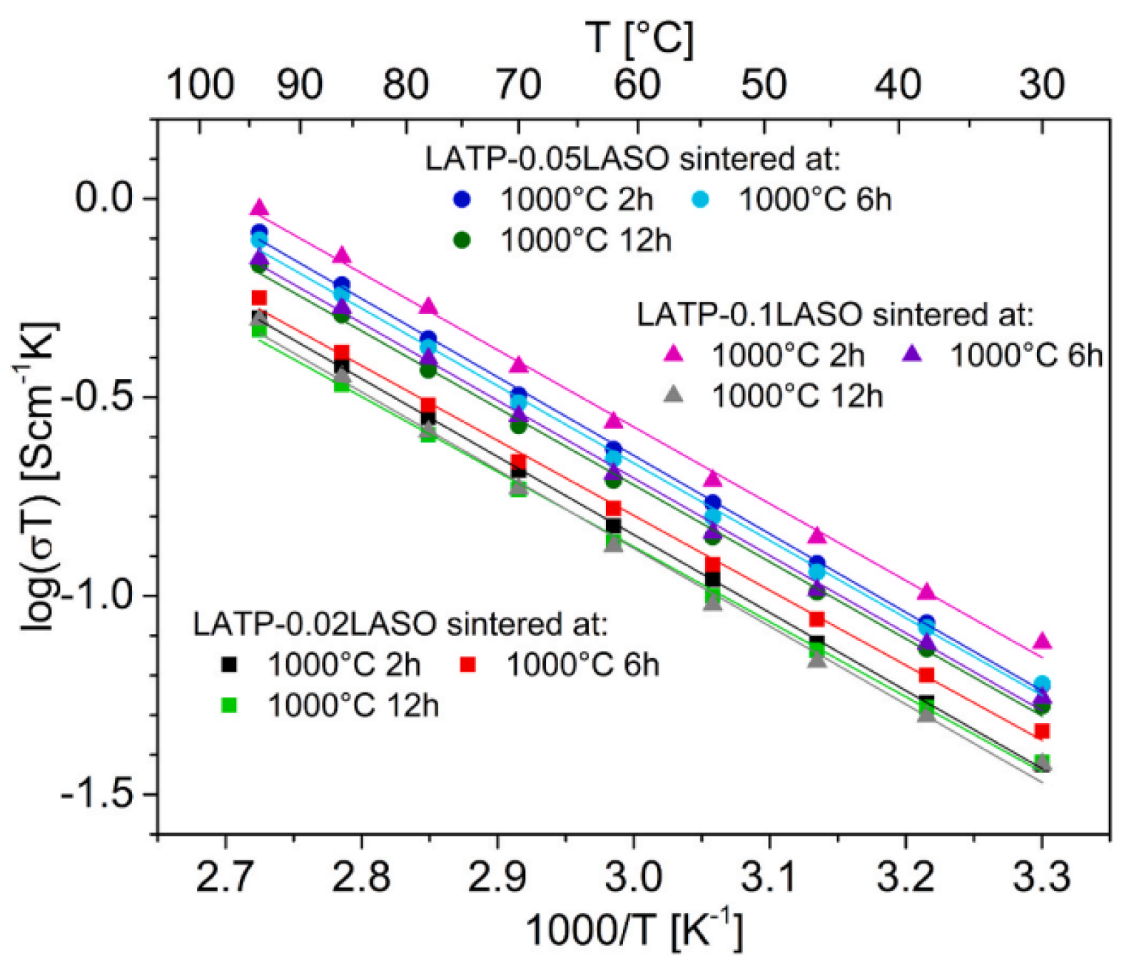
The electrical characteristics of LATP-LASO ceramics sintered at various temperatures and times were examined in the study. As seen in Figure 17, the results showed that, generally speaking, the ionic conductivity was about 10 3 S/cm, independent of the sintering conditions. On the other hand, samples sintered at 800 °C and containing less LASO ( L i A l S i O 4 ) exhibited somewhat lower conductivity.
According to the analysis, raising the sintering temperature enhanced grain adhesion but also resulted in microcracks that impacted conductivity. An Arrhenius model described the temperature dependence. The materials with lower LASO content and those sintered at lower temperatures had slightly different grain compositions, which affected their electrical properties, according to the activation energy values.

4.2.2. Dielectric

When exposed to external electric fields, dielectric materials, also known as dielectrics, can undergo polarization, conductivity, loss, and breakdown. Dielectrics use induction rather than conduction to transmit, store, or record electric field effects, in contrast to conductors, which use the flow of electric charges to conduct electricity [125].
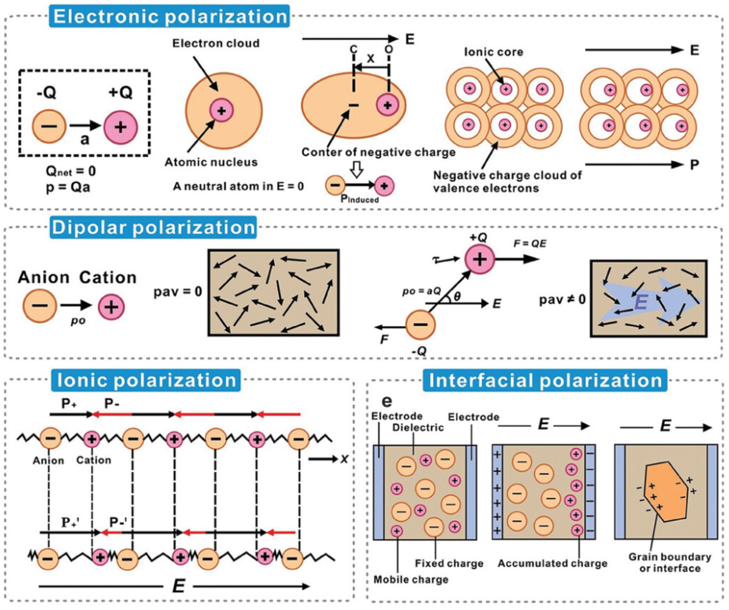
A material’s polarization behavior and charge distribution are correlated with its dielectric constant. Controlling the electrical characteristics of materials requires an understanding of the dielectric constant’s origin. As seen in Figure 18, each polarization mechanism displays distinct properties of dielectric materials.
Positive and negative charges in dielectric materials (insulators) separate when they are subjected to an external electric field. This makes the material appear polarized by producing an internal electric field in the dielectric and an electric dipole moment. We refer to this phenomenon as dielectric polarization.
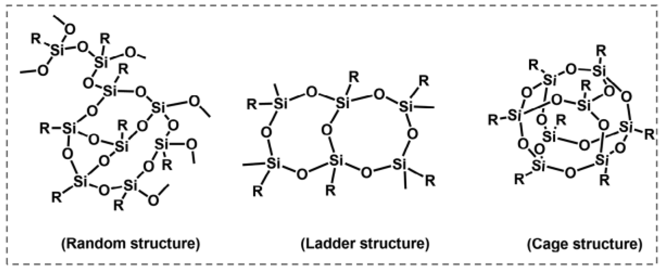
Dielectric materials come in a variety of forms and can be divided into two categories: silicon-based and non-silicon-based. Sesquioxides are silicon-based materials, whereas organic polymers and amorphous carbon are non-silicon-based materials A sesquioxide refers to an oxide compound in which the atomic ratio of the constituent element to oxygen is 2:3 (Figure 19).
Polymers are the most popular and adaptable class of dielectric materials [126]. From capacitors and insulators to flexible electronics and energy storage systems, their inherent qualities—such as light weight, mechanical flexibility, low cost, and ease of processing—make them perfect for a variety of applications [127]. Because of their high breakdown voltage, low dielectric loss, and exceptional dielectric strength, polymers like polyvinylidene fluoride (PVDF) [128], polyethylene (PE) [129], and polypropylene (PP) [130] are frequently used.
Dipolar contributions are particularly important in polar polymers, and the polarization mechanism in polymeric dielectrics is mainly of an electronic and orientational nature [131]. Polymer chains, in contrast to crystalline inorganic materials, show different levels of disorder, which can be adjusted to maximize dielectric performance.

4.3. Polymeric Composites

Research into advanced materials for supercapacitor applications has been fueled by the increasing need for energy storage systems with high power density, fast charging, discharge capacity, and long cycle life. Conducting polymer composites are one of the materials being studied. Note Whether they are man-made or natural, polymers are made up of very large molecules, or macromolecules, which are repeats of simpler chemical building blocks called monomers. Because of their special blend of electrical conductivity, flexibility, and ease of synthesis, polymers—which include proteins, cellulose, and nucleic acids—have emerged as promising candidates for many parts of living organisms [132].
Because of their special set of characteristics that make them appropriate for energy storage applications, conducting polymers (CPs) have found extensive use in supercapacitors. Supercapacitors, sometimes referred to as electrochemical capacitors or ultracapacitors, are energy storage devices that use the electrostatic separation of charge to store and release energy. Because of their high conductivity, large surface area, flexibility, processability, and pseudocapacitive qualities, they are among the first options for supercapacitor applications.
The creation of the electric double layer (EDLC) and Faradaic processes, also known as pseudocapacitance, are the two main ways that supercapacitors store energy [133]. There is no chemical reaction involved in the electrostatic storage of energy at the interface between the electrode and the electrolyte in EDLCs [134]. Long operational lifetimes and quick charge/discharge cycles are made possible by this mechanism, which is highly dependent on the electrode material’s surface area and porosity [135].
Because CPs have unique electronic characteristics, their electrical conductivity mechanism is different from that of conventional conducting and semiconducting materials. The formation and type of polymers influence electrical conductivity in CPs, which only happens when the electrons are activated thermally or photolytically. There are both ionic and electronic components to this conduction mechanism. An extremely conductive pathway is created by the delocalization of π -electrons along the polymer chain.
There are three essential conditions for a polymer to be electrically conductive [136,137,138]:
  • To achieve high electronic mobility, the molecule must have a linear structure with s p 2 hybridized carbon centers forming the “backbone” that permits electrons in the p z orbitals to delocalize.
  • In order to increase electron conductivity and create an overlap of bonds, the molecule must have extended conjugation and a continuous matrix of “p” orbitals that can align.
  • It is essential to introduce dopants or charge carriers because the charge they create gives the polymer conductivity. By decreasing the gaps between particles, increasing the doping level increases conductivity by creating more charges in the polymer.
Moreover, the conducting polymer’s conductivity rises with molecular distance and is also temperature dependent.

Electrical Properties

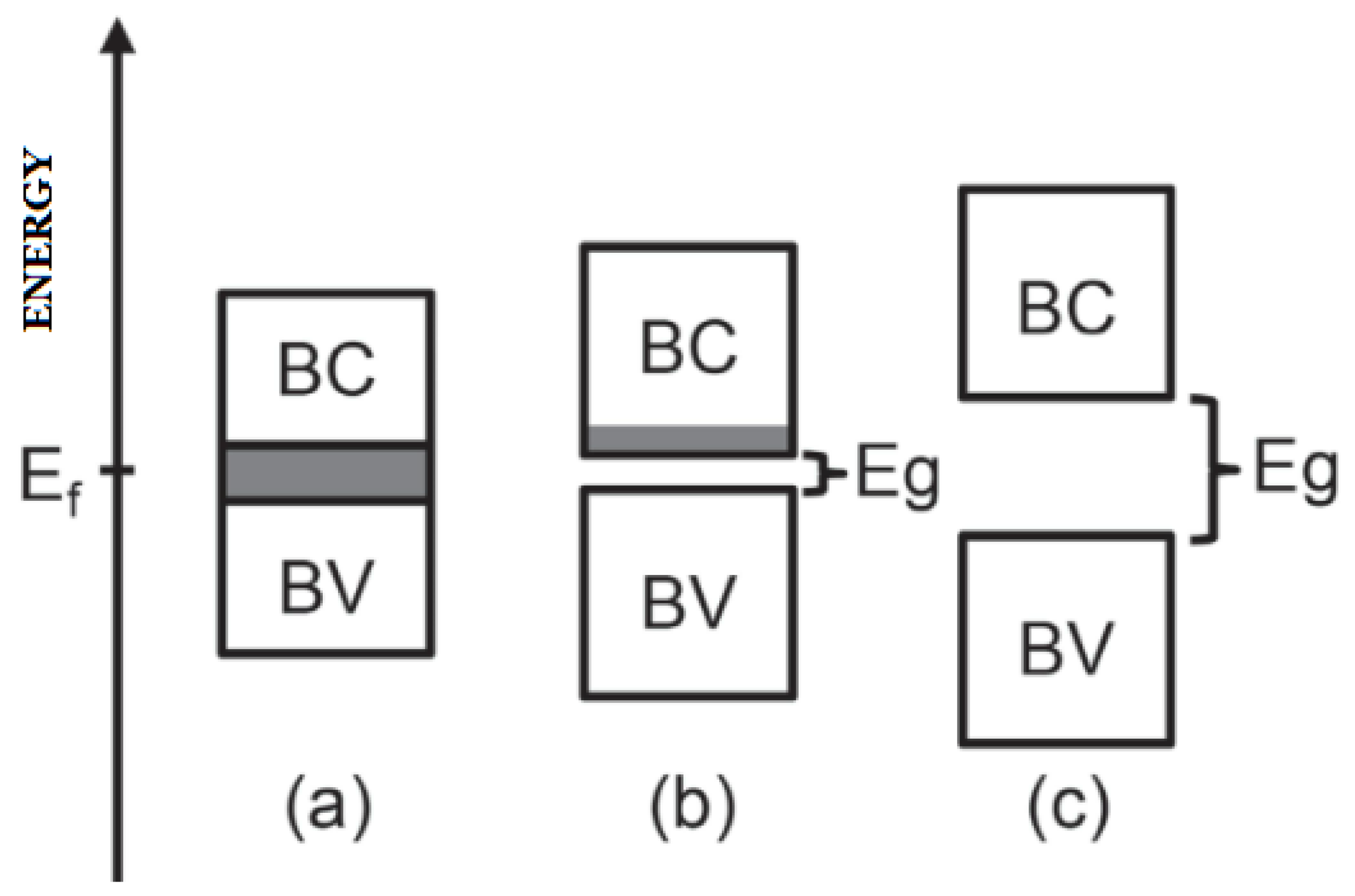
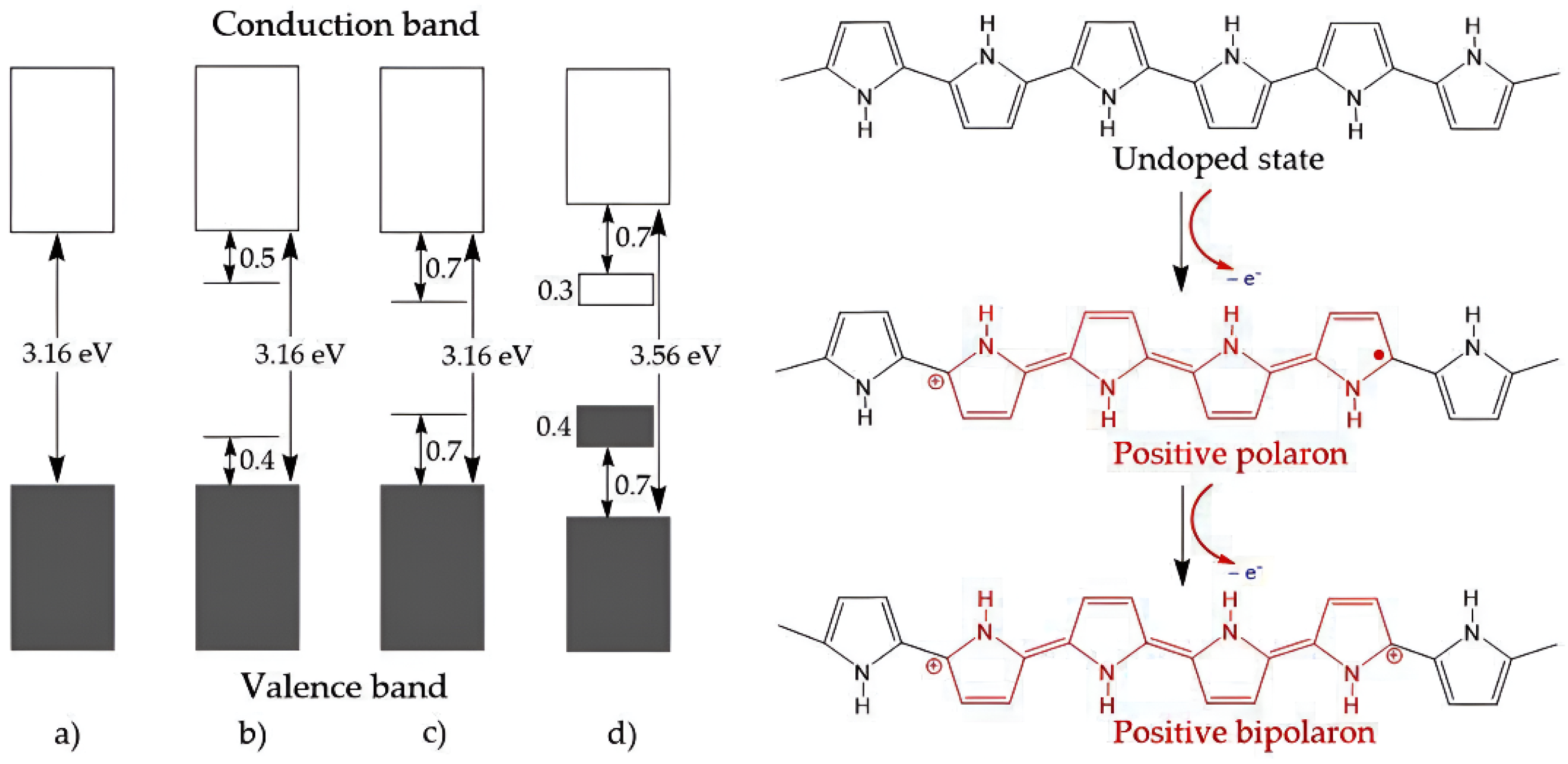
It is common practice to analyze electronic band structures in order to comprehend the electrical properties of materials. As seen in Figure 20, The energy difference between the conduction and valence bands, or the bandgap, establishes whether a substance is an insulator, conductor, or semiconductor. In semiconductors, the bandgap is small, allowing conduction through the movement of excited electrons, whereas in intrinsically conducting materials, this difference is lessened, permitting an overlap between the bands. Insulators lack conductivity because of their large bandgap, which stops electrons from moving between the bands.
Dopants have an impact on the electrical conductivity of conjugated polymers; by altering the dopant content, they significantly change the conductivity. Apart from doping, the electrical properties are also influenced by the length and arrangement of the polymer chain. By displacing charge carriers in the polymer chains and donating or accepting electrons from the polymers through redox reactions, dopants can increase conductivity.
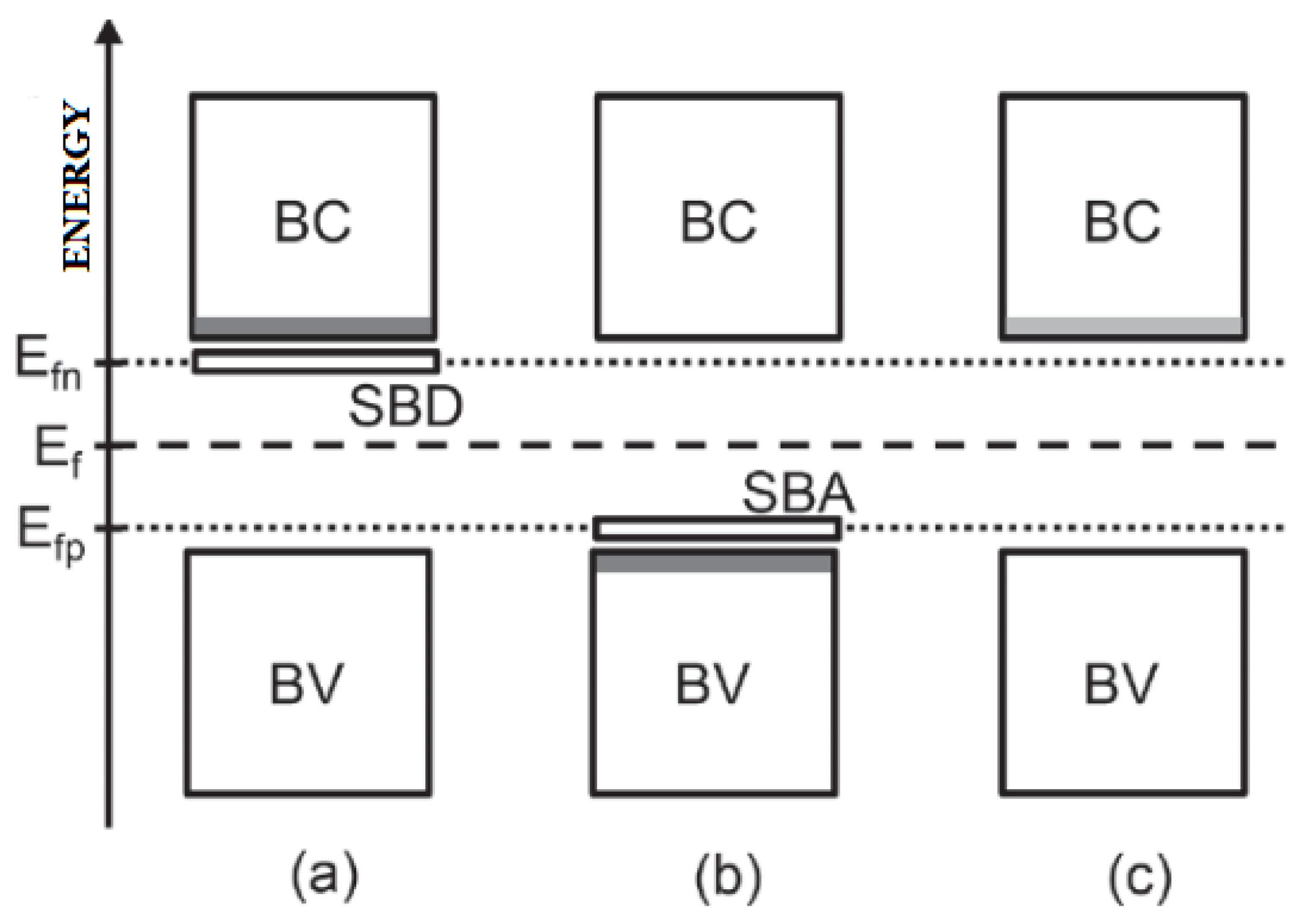
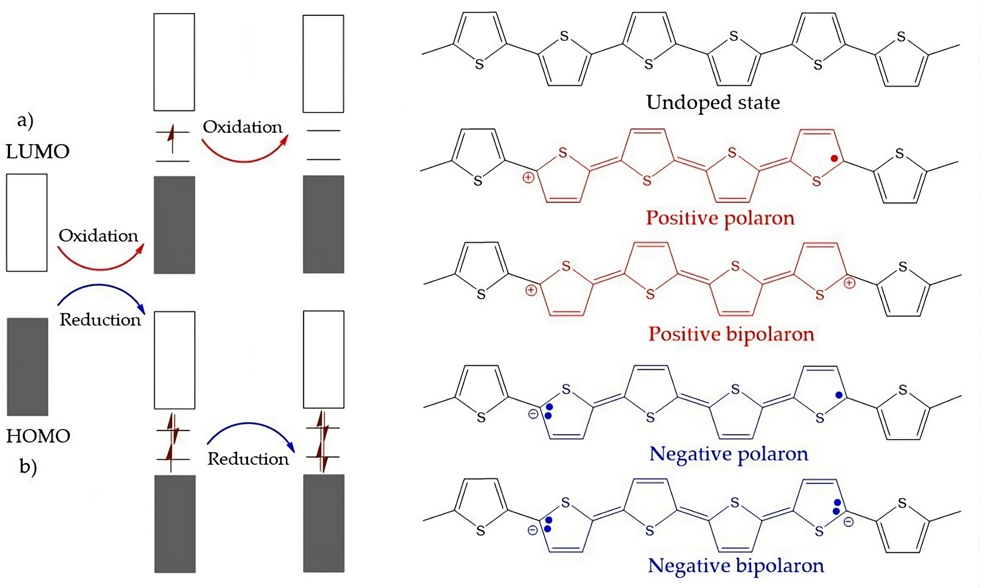
As seen in Figure 21, the p-type and n-type dopants have different effects, either producing holes or adding more electrons to the structure. The conductivity of conducting polymers is partially explained by the electronic band theory, but physical and chemical factors—such as charge density waves and conjugative bonding systems—are also taken into account.

4.4. Types of Conductive Polymers

Their structural backbone is typically made up of a linear structure made up of repeating conjugated monomers. Common examples of CPs are polyacetylene (PAC), polypyrrole (PPy), polyaniline (PANI), and polythiophene (PTh), as shown in Table 4. Their structural backbone is typically made up of a linear structure made up of repeating conjugated monomers. Common examples of CPs are polyacetylene (PAC), polypyrrole (PPy), polyaniline (PANI), and polythiophene (PTh), as shown in Table 4.
The two primary categories of these polymers—intrinsically conductive polymers (ICPs) [141,142,143] and extrinsically conductive polymers (ECPs) [144]—each have unique traits that affect their conductive qualities.
Electroactive conjugated polymers like polyaniline, polypyrrole, and polythiophenes make up ICPs. Electrical conduction along the polymer chain is made possible by the conjugated structure of these materials. Ingredients in the second category, extrinsically conductive polymers, also referred to as polymers with conductive components, naturally transfer charge, giving the polymer material electrical conductivity.

4.4.1. Intrinsically Conductive Polymers-ICPs

Polymers that naturally show electrical conductivity without doping or further processing are known as intrinsically conductive polymers, or ICPs. Their unique chemical structure, which promotes the flow of charge carriers along the polymer chain, is the source of this conductivity. Polyaniline, polypyrrole, and polythiophene are typical examples of ICPs [132,145,146].
These polymers stand out for fusing the beneficial qualities of metals and plastics. However, their practical applications are limited by issues with their electrical properties, stability, and processability. An ICP and a p-type doping procedure are shown in Figure 22.
Moreover, these are artificial materials made of elements like hydrogen, oxygen, nitrogen, sulfur, and carbon. They have conductivity similar to metals, low density, and high mechanical strength. By altering the chemical structure of conjugated polymer chains, dopant dosages, and synthesis conditions, their electrical characteristics can be changed.

4.4.2. Extrinsically Conductive Polymers-ECPs

Solvent blending or fusion produces extrinsically conductive polymers (ECPs), where the mixtures encourage electrical conduction. A non-conductive polymer-coated electrode surface is polymerized to produce these polymers. Externally added components are the source of ECP conductivity. They have qualities like mechanical strength, corrosion resistance, and good electrical and thermal characteristics. They have comparable mechanical qualities to ICPs, despite having a lower electrical conductivity. Furthermore, ECPs can combine metallic, non-metallic, organic, and other polymers to create conductive polymer composites (CPCs), which can be binary, ternary, or quaternary.
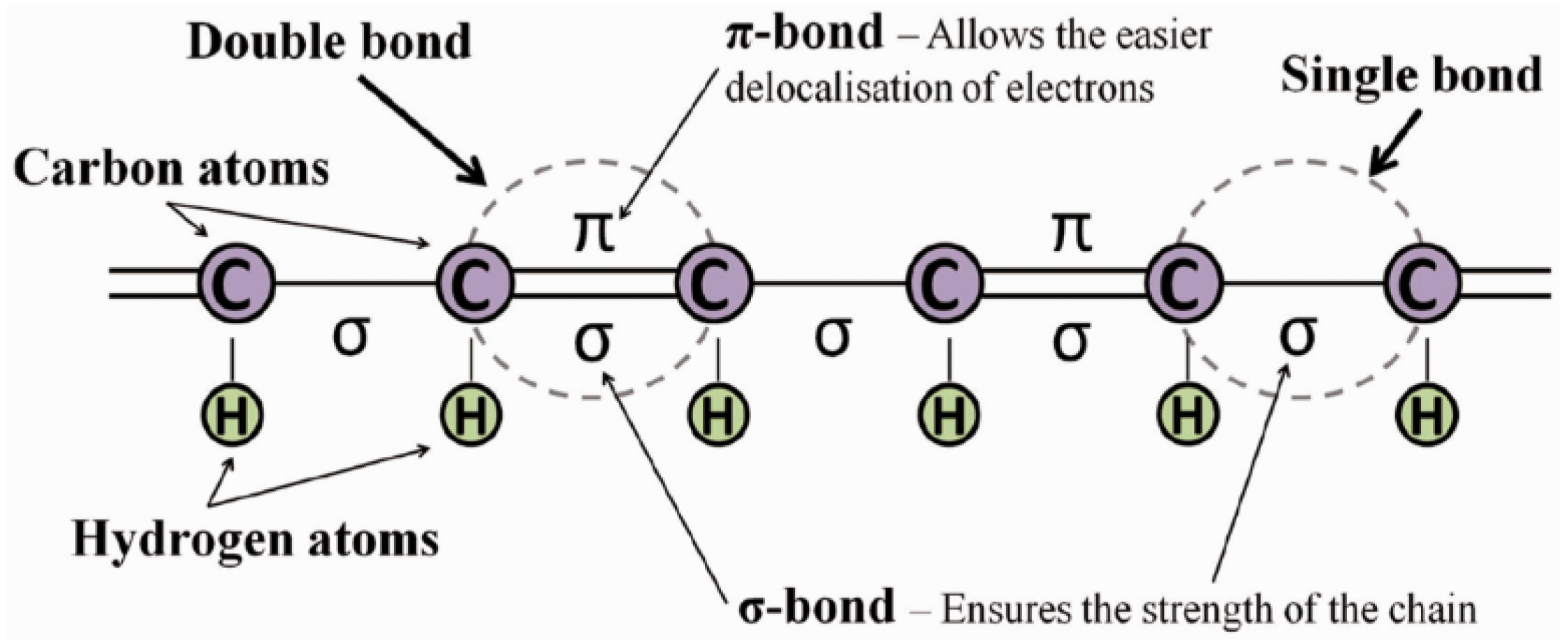
In general, polymers need to fulfill two key requirements in order to become conductive. First, conjugated double bonds—alternating single and double bonds—must be present in conductive polymers. One of these bonds, the “sigma” ( σ ) bond, is highly localized and creates strong chemical bonds. Electrical conduction is also made possible by the presence of a “pi” ( π ) bond in each double bond, which is weaker and less localized. The process mentioned above is shown in simplified form in Figure 23.

4.5. Applications of Conductive Polymers

As a summary of the CPs discussed above, these polymers conduct electricity similarly to metals and inorganic semiconductors. Their structure consists of alternating σ and π bonds, and their electrical and optical characteristics are caused by delocalized electrons. Energy storage devices [148,149], LEDs [150], sensors [151,152,153], bioelectronics, tissue engineering [154], solar cells [155], catalysis [156], and anticorrosive coatings [157,158] are among the applications.
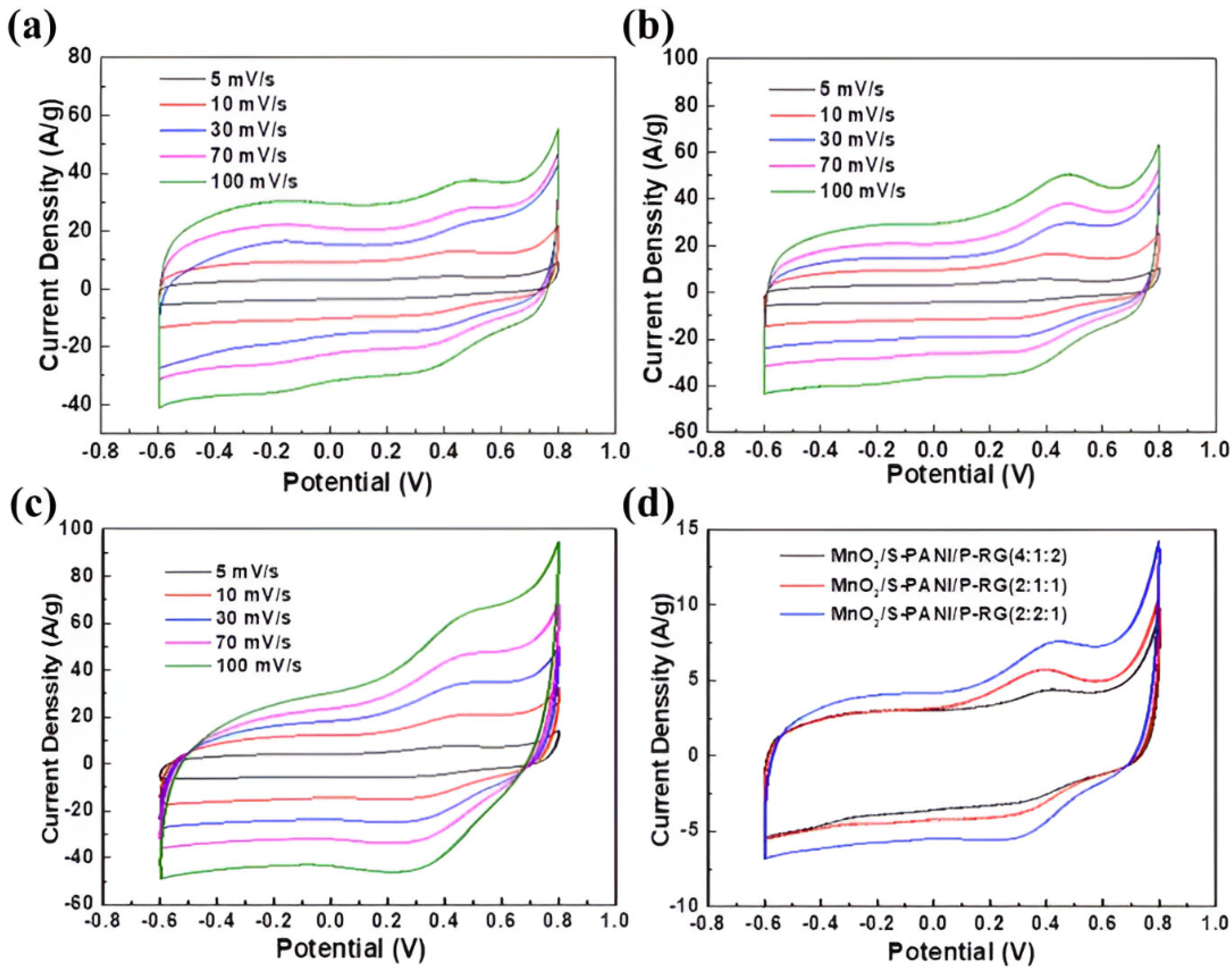
Since they combine electrical conductivity, flexibility, and ease of processing, conductive polymer composites have garnered a lot of interest for use in supercapacitors [159]. With a high power density and quick charge–discharge times, supercapacitors—also referred to as electrochemical capacitors or ultracapacitors—are energy storage devices that fall somewhere between conventional capacitors and batteries. The performance of supercapacitors can be enhanced with the help of these composites.
In order to create composites, they are frequently mixed with carbon-based substances like graphene, carbon nanotubes, carbon black, and metallic oxides. As seen in Figure 24, which illustrates the addition of different substances to polymers and the notable changes in the materials’ electrical properties, these composites, which are created using a variety of polymerization techniques, overcome the limitations of individual materials by improving electrical conductivity and capacitance, allowing their use in a variety of applications.

4.6. Composites with Nano-Reinforcements

Solid materials made up of several phases, known as nanocomposites, have at least one phase with nanometric dimensions (one, two, or three axes), which alters the material’s characteristics when the size of its constituents drops below a “critical size.” The goal of the nanoscale interaction is to create synergy between the various components, including nanoparticles, nanofibers, and nanoclays. According to the relationship between the constituents’ surface area and volume, a reduction in these dimensions produces significant interfaces for enhancing the material’s properties [39].
By combining non-metallic, metallic, and polymeric materials, these nanocomposites create a multiphase material while preserving key properties and overcoming flaws. Glass fibers and other fibrous materials are part of the dispersed phase, whereas metallic, inorganic, non-metallic, or polymeric materials can make up the continuous phase [161,162].
Based on their matrix materials, nanocomposite materials are categorized into three groups:
  • Ceramic matrix nanocomposites (CMNC);
  • Polymer matrix nanocomposites (PMNC);
  • Metal matrix nanocomposites (MMNC).
Composites with nano-reinforcements, or materials that combine various nanofillers with polymeric matrices, have generally gained a lot of attention from scientists because of their potential to revolutionize a number of industries. According to the literature, advanced manufacturing techniques are crucial for maximizing the functionality and performance of these materials, with a focus on interfacial adhesion and structural integrity [163].

4.6.1. Carbon Nanotubes

The hexagonal lattice of carbon atoms forms the cylindrical nanostructures known as carbon nanotubes (CNTs), which resemble rolled-up graphene sheets. Multi-walled carbon nanotubes (MWCNTs), which are composed of several concentric graphene layers, and single-walled carbon nanotubes (SWCNTs), which are made up of a single graphene layer, are the two main types [164].
These nanomaterials are praised for their remarkable physical characteristics, such as their variable electrical conductivity, which can be either metallic or semiconducting depending on their structural chirality, outstanding thermal conductivity, and high tensile strength, which can be up to 100 times greater than steel with only a fraction of the weight. They are even more applicable in sophisticated engineering systems due to their exceptional mechanical flexibility.
Carbon nanotubes have found use in a variety of innovative applications because of their special blend of mechanical, thermal, and electrical characteristics. They are used in electronics as parts of conductive interconnects, flexible displays, and transistors. CNTs are mixed with metals and polymers to create composite materials, which are lightweight, strong, and used in high-performance sporting goods and aerospace. They increase the capacity and charge/discharge rates of lithium-ion batteries and supercapacitors in the energy sector [165].
Additionally, their nanoscale size and biocompatibility allow for possible uses in biosensing and targeted drug delivery in the biomedical field [166]. Because of their porous structure, CNTs are also used in filtration membranes for water purification. Notwithstanding their potential, issues like high cost, purification, large-scale production, and safety concerns still need to be resolved. However, with expected advances in advanced electronics, sustainable energy, and nanomedicine, the future of carbon nanotubes is still bright [167].

4.6.2. Graphene and Derivatives

The distinct electrical characteristics of graphene and its derivatives, including graphene oxide (GO), reduced graphene oxide (rGO), and doped graphene, make them promising for a range of technologies [11]. High conductivity, adjustable behavior, and the possibility of application in transistors, sensors, and batteries are some of these characteristics. Because of its high electron mobility and electrical conductivity, pure graphene is perfect for high-speed electronic devices. Because of its distinct band structure, electrons can move like massless particles, which results in remarkable performance in devices like transistors.
Because of structural disruptions, GO is usually an insulator, whereas rGO uses reduction processes to restore some conductivity. Given graphene’s inherent zero band gap, the ability to dope graphene to be either n-type or p-type opens up possibilities for semiconductor applications [159].
Defect scattering dominates the mobility, which is almost temperature-independent between 10 K and 100 K. Acoustic phonon scattering can reach intrinsic limits of 200,000 cm 2 ( V · s ) 1 at a carrier density of 10 12 cm 2 , which is 10 × 10 6 times higher than copper [168].
When graphite is oxidized, oxygen functional groups are added, disrupting the s p 2 carbon network and converting it into an electrical insulator. It has a very low conductivity, usually between 10 6 and 10 4 S/m. The loss of π -conjugation is the cause of this low conductivity; research indicates that resistivity is around 10 12 Ω m Because GO disperses in polar solvents like water, it is frequently used as a precursor for rGO or in applications that need insulation, like dielectrics in capacitors [169].
By partially restoring the s p 2 network and enhancing conductivity, rGO is produced by reducing GO by thermal, chemical (such as with hydrazine or hydroiodic acid), or other means. Depending on the reduction technique, rGO’s conductivity can vary from 10 2 to 10 4 S/m [170]. Because of lingering defects and oxygen groups, its electron mobility is less than that of pure graphene. Transparent electrodes for touch screens and electrochemical sensors employ rGO; films reduced with hydroiodic acid exhibit enhanced flexibility and a conductivity of about 10,330 S/m.

4.6.3. Electrical Properties

According to some research, inorganic-organic polymers with this kind of reinforcement can be readily processed to produce materials that are better than those made of conventional polymers [171]. Processability, solubility, and thermal stability are all enhanced when polymer chains are added to composite systems. Due to its water solubility and biocompatibility, polyvinyl alcohol (PVA) finds extensive use in biomedical, pharmaceutical, and technology applications.
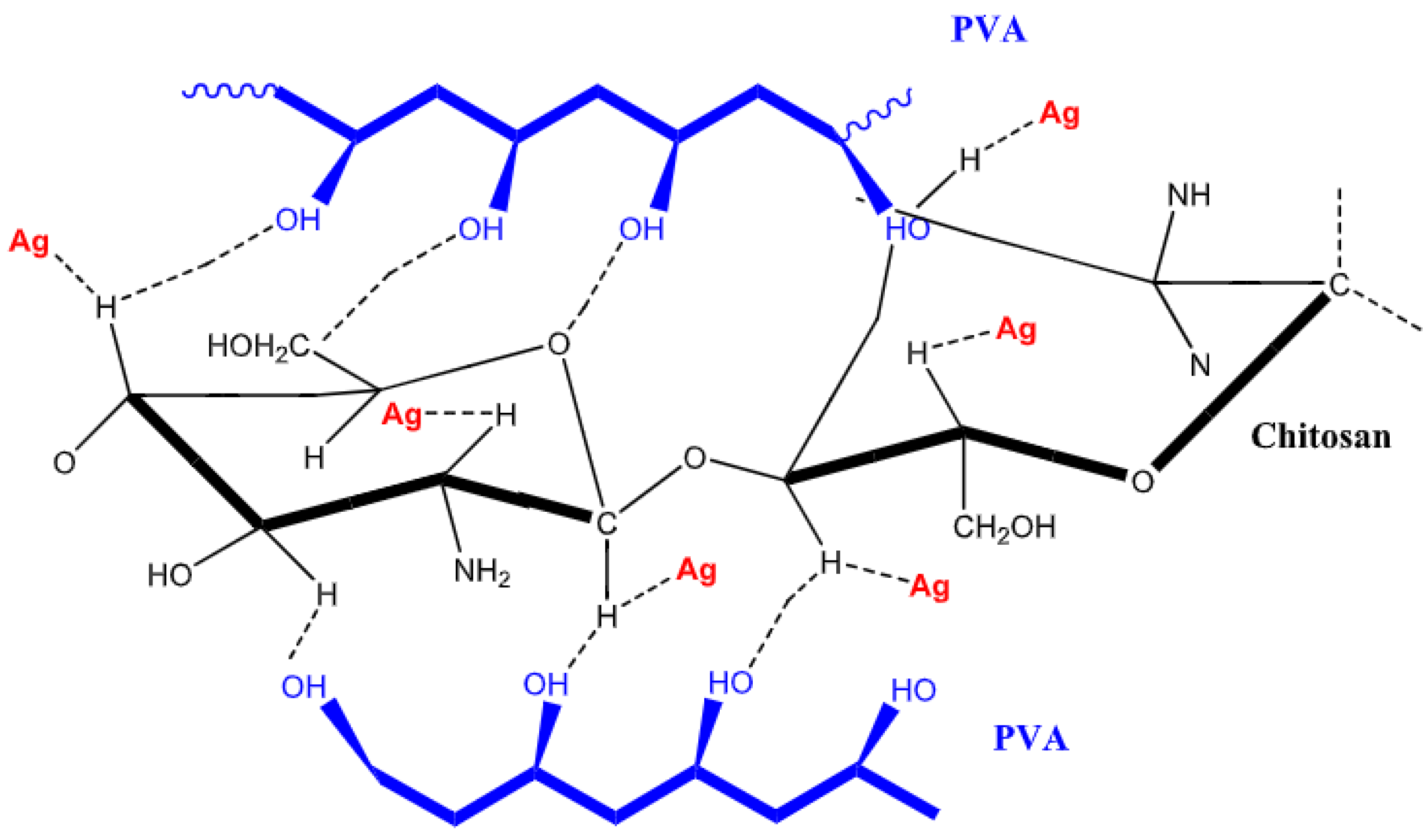
Although there are few studies on the precise impact of metallic nanoparticles in reinforced polymer blends, their addition has been shown to enhance the mechanical, electrical, thermal, and antibacterial qualities of polymers. The chemical stability, thermal conductivity, antimicrobial activity, and optical properties of silver nanoparticles (Ag NPs) are especially noteworthy. They are a safe and sustainable choice for biomedical applications because they have antibacterial activity without releasing harmful substances. The PVA polymer composite with chitosan (Cs) and silver nanoparticles is synthesized as shown in Figure 25.
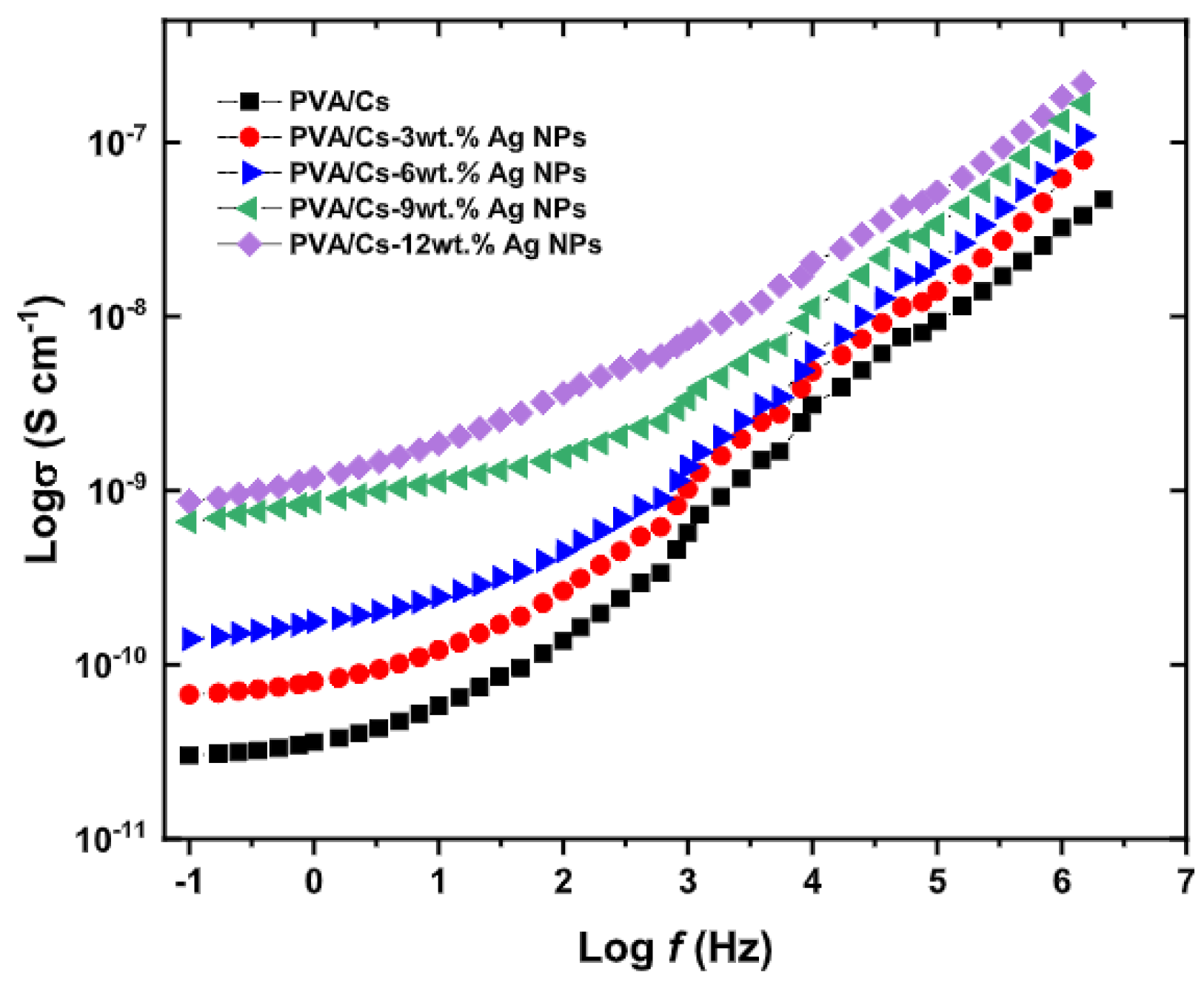
In comparison to pure PVA/Cs, the study demonstrates that the addition of silver nanoparticles (Ag NPs) considerably raises the AC electrical conductivity of PVA/Cs-Ag nanocomposites. According to Figure 26, this increase is explained by the formation of a 3D conductive network that promotes the concentration of charge carriers in the PVA/Cs matrix by facilitating charge transport.
A conduction mechanism associated with correlated barrier hopping (CBH) is suggested by the conductivity analysis as the concentration of Ag NP increases. An improved charge conduction mechanism is indicated by the filled films’ significantly higher DC conductivity than that of the virgin films. The homogeneous dispersion of nanofillers, the polarity of the polymers and nanoparticles, and the crystalline structure of the nanoparticles all affect the composites’ electrical conductivity. Because of the effective movement of charge carriers in the nanocomposites, frequency dependence demonstrates an increase in conductivity at higher frequencies.
Understanding the dielectric properties of nanocomposites is crucial for understanding their charge storage capacity in addition to their conductivity behavior. Applying the Debye model using the following formula:
ε = ε + j ε
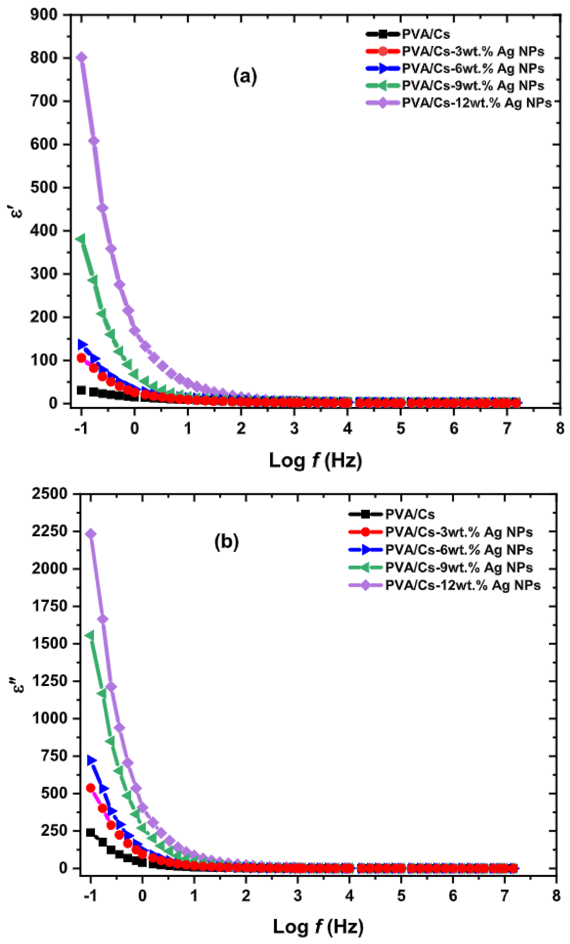
The complex dielectric behavior of PVA/Cs films with and without the addition of silver nanoparticles (Ag NPs) could be computed. As illustrated in Figure 27, it was found that the real part of the dielectric constant ε decreases with increasing frequency. This is a typical behavior in polar materials. This effect is explained by the electrodes’ blocking of charge carriers and the dipoles’ decreased alignment with the fluctuating electric field. The dielectric constant ( ε ) decreases as the Ag NP content rises, suggesting that the composites’ insulating properties are diminished, and their conductivity is enhanced.
As frequency increases, so does the imaginary part of the dielectric constant ( ε ). The presence of mobile charges within the polymer causes greater dielectric loss at low frequencies, increasing energy dissipation. The electric field’s periodic reversal at high frequencies reduces dielectric loss by preventing excessive ion diffusion. A decrease in the charge accumulation polarization phenomenon is linked to a decrease in the loss factor. These outcomes support the composites’ enhanced conductivity following the addition of Ag NPs.
It is suggested that future research incorporate complementary dielectric analysis using complex impedance spectroscopy in order to further refine and solidify the findings. Interfacial resistances and capacitances could be measured using this method, which would also make it possible to distinguish between ionic and electronic transport mechanisms more precisely. Finding the silver nanoparticles’ percolation threshold within the PVA/Cs matrix is also essential for maximizing electrical conductivity without sacrificing the composite’s mechanical and dielectric integrity.
Comprehensive morphological analysis using Atomic Force Microscopy (AFM) or Scanning Electron Microscopy (SEM) in conjunction with Energy Dispersive X-ray Spectroscopy (EDS) would enable a clear connection between the size and distribution of Ag NPs and the observed dielectric behavior. Additionally, the use of theoretical models like Maxwell–Garnett or Bruggeman would support the logical design of the composite by offering predictive insights into how different volume fractions and nanoparticle sizes would affect the dielectric constants.
To find possible uses in sensors, capacitor dielectric layers, or flexible electronic substrates, it would also be beneficial to assess the electrical characteristics under actual operating conditions, such as changes in temperature, humidity, and AC/DC voltage regimes. In conclusion, thermal aging tests and accelerated operational cycling would provide vital information about the material’s robustness and temporal stability, both of which are necessary for its actual use in industrial applications.

5. Prospects

All things considered, every subject covered in this chapter about the electrical characteristics of composite materials is consistent with the theory put forth, indicating its high significance for the study. For improving material performance and its corresponding applications, each of the structures that have been discussed is essential.
In general, electrical conductivity is a crucial characteristic of composites. Improvements in metal-reinforced plastic composites are directly correlated with the amount of metallic filler added. This idea is based on the theory that explains how adding metallic nanoparticles to a polymer matrix raises the concentration of charge carriers, which improves electrical conductivity.
Advanced characteristics like enhanced electrical conductivity, antimicrobial activity, and thermal stability are also provided by nanocomposites, which are made of materials at the nanometric scale. According to the literature, these materials use nanoscale phase interactions to produce synergistic properties, demonstrating the usefulness of nanocomposites in a variety of applications.
Furthermore, ceramic composites’ dielectric properties are essential to their capacity to store charge, increasing their potential applications, such as in supercapacitors. The theory explaining dielectric behavior in polymeric materials is consistent with the dielectric constant, which is affected by the presence of metallic nanoparticles. These ideas support the literature review’s discussion of the significance of electrical characteristics in the real-world use of composites.

6. Conclusions

The electrical characteristics of composites made of metals, ceramics, polymers, and nanocomposites reinforced with nanoscale particles were thoroughly reviewed in this work. The primary goal of collecting and evaluating these materials’ electrical properties was accomplished, providing a strong basis for further research. The key contributions and findings are as follows:
  • A variety of composite-type materials covered in the review included metal, ceramic, and polymer-based composites, as well as nanocomposites with nanoscale reinforcements.
  • Impact of Metallic Nanoparticles: the analysis showed that adding metallic nanoparticles can greatly improve polymer composites’ electrical conductivity, mostly because they create conductive networks inside the matrix.
  • Significance of Dielectric and Electrical Behavior: a thorough explanation of electrical conductivity and dielectric characteristics was given, with a focus on how these characteristics are affected by the interactions between composite materials in different scenarios.
  • Contribution to the Literature: This review makes a significant contribution to the academic community by compiling current and pertinent studies, acting as a reference and a stimulant for more in-depth, focused research.
  • Potential Applications: The electrical behavior of the composites investigated in this work provides opportunities for use in important fields like environmental technologies, biomedical devices, and electronics.
Building on these discoveries, the future of electrically conductive composites is anticipated to be shaped by a number of encouraging trends:
  • Hybrid Composites: the creation of systems that combine various fillers, like metallic particles, with graphene or carbon nanotubes to enable multifunctionality and take advantage of synergistic effects.
  • Sustainable Materials: In order to lessen the environmental impact, it will be more crucial to incorporate biodegradable or bio-based matrices with environmentally friendly conductive fillers.
  • Electrically conductive composites are anticipated to be essential in the development of wearable technology, flexible electronics, and intelligent sensors that can react to chemical, mechanical, or thermal stimuli.
  • Advanced processing methods: precise control over filler dispersion and composite architecture will be made possible by the application of additive manufacturing (such as 3D printing) and nano-engineering techniques.
  • Interface Optimization: To improve electrical pathways and long-term stability, future research will probably concentrate on customizing the interface between the matrix and conductive filler.
In summary, this study not only provides a thorough understanding of the state of electrically conductive composites today, but it also establishes the framework for upcoming advancements. Researchers can increase the potential of composites in cutting-edge technological applications by comprehending the basic interactions within these materials and spotting new trends.

Author Contributions

Conceptualization, T.J.L.; methodology, S.N.M.; validation, A.M.d.A., S.N.M. and F.M.A.-M.; formal analysis, T.J.L., F.M.A.-M. and A.M.d.A.; investigation, T.J.L. and A.M.d.A.; resources, S.N.M.; writing—original draft preparation, T.J.L. and A.M.d.A.; writing—review and editing, T.J.L. and A.M.d.A.; visualization, F.M.A.-M. and S.N.M.; supervision, F.M.A.-M. and S.N.M.; project administration, S.N.M.; funding acquisition, F.M.A.-M. and S.N.M. All authors have read and agreed to the published version of the manuscript.

Funding

This study was financed in part by the Brazilian Agency CAPES (Coordenação de Aper feiçoamento de Pessoal de Nível Superior), Protocol#001.

Data Availability Statement

Not applicable.

Acknowledgments

We extend our deepest gratitude to the Military Institute of Engineering (IME) for their invaluable technical support and access to facilities that significantly contributed to the advancement of this research.

Conflicts of Interest

The authors declare no conflicts of interest.

Abbreviations

The following abbreviations are used in this manuscript:
AFMAtomic Force Microscopy
ICPExtrinsically Conductive Polymers
ICPIntrinsically Conductive Polymers
LMLiquid Metals
SEMScanning Electron Microscopy
WC-CoTungsten carbide-cobalt
A l Aluminum
C u Copper
C P Conductive Polymers
C s Cytosine
eElectron
e V Electron-Volt
G a Gallium
G e Germanium
G O Graphene Oxide
L i 2 S Lithium Sulfide
N e Avogadro’s number
N i Nickel
P A C Polyacetylene
P A N I Polyaniline
P E Polyethylene
P P y Polypyrrole
P S Polystyrene
P T h Polythiophene
P V C Polyvinyl Chloride
P V A Polyvinyl Alcohol
S i Silicon
S i C Silicon Carbide
v d Drift velocity
Y 2 O 3 Yttrium Oxide
μ Electric permeability
μ e Electron mobility
ν Mean electron velocity
ρ Electrical resistivity
σ Electrical conductivity
τ Mean free path
ε Dielectric constant

References

  1. Simões, S. High-performance advanced composites in multifunctional material design: State of the art, challenges, and future directions. Materials 2024, 17, 5997. [Google Scholar] [CrossRef] [PubMed]
  2. Matsuda, R.; Isano, Y.; Ota, H. Stretchable composites with electrical conductivity. Flex. Print. Electron. 2025, 10, 013001. [Google Scholar] [CrossRef]
  3. Dhingra, A.; Kumar, R.; Thakur, O.; Pandey, R. Advancements in hexaferrite composite materials for electromagnetic interference shielding solutions. Sustain. Mater. Technol. 2025, 44, e01333. [Google Scholar] [CrossRef]
  4. Islam, M.; Hossain, M.S.; Adak, B.; Rahman, M.M.; kubra Moni, K.; Nur, A.S.; Hong, H.; Younes, H.; Mukhopadhyay, S. Recent advancements in carbon-based composite materials as electrodes for high-performance supercapacitors. J. Energy Storage 2025, 107, 114838. [Google Scholar] [CrossRef]
  5. Amin, A.S.; Caidi, A.; Lange, T.; Radev, I.; Sandbeck, D.J.S.; Philippi, W.; Kräenbring, M.A.; Öztürk, M.; Peinecke, V.; Lerche, D.; et al. Key Control Characteristics of Carbon Black Materials for Fuel Cells and Batteries for a Standardized Characterization of Surface Properties. Part. Part. Syst. Charact. 2025, 42, 2400069. [Google Scholar] [CrossRef]
  6. Faniband, B.; Chandra, S.S.; Pattar, J.; Rao, H.A.; Sreekanth, R.; Mahendra, K.; Murugendrappa, M.; Nataraja, S.K.; Nagaraja, M. Exploring the charge transport mechanism, electrical conductivity, and dielectric properties of polyaniline/tin sulfide nanocomposites. Polym. Compos. 2025, 46, 8076–8087. [Google Scholar] [CrossRef]
  7. Elbakyan, L.; Zaporotskova, I. Polypropylene Modified with Carbon Nanomaterials: Structure, Properties and Application (A Review). Polymers 2025, 17, 517. [Google Scholar] [CrossRef]
  8. Barra, A.; Ferreira, N.M.; Poças, F.; Ruiz-Hitzky, E.; Nunes, C.; Ferreira, P. Boosting through-plane electrical conductivity: Chitosan composite films with carbon-sepiolite and multiwalled carbon nanotubes. Carbon 2025, 231, 119691. [Google Scholar] [CrossRef]
  9. Lai, F.; Getzner, L.; Rotaru, A.; Molnár, G.; Cobo, S.; Bousseksou, A. Drastic Enhancement of Electrical Conductivity of Metal–Organic Frameworks Displaying Spin Crossover. Chem. Mater. 2025, 37, 636–643. [Google Scholar] [CrossRef]
  10. Lalire, T.; Longuet, C.; Taguet, A. Electrical properties of graphene/multiphase polymer nanocomposites: A review. Carbon 2024, 225, 119055. [Google Scholar] [CrossRef]
  11. Reghat, M.; Mirabedini, A.; Tan, A.M.; Weizman, Y.; Middendorf, P.; Bjekovic, R.; Hyde, L.; Antiohos, D.; Hameed, N.; Fuss, F.K.; et al. Graphene as a piezo-resistive coating to enable strain monitoring in glass fiber composites. Compos. Sci. Technol. 2021, 211, 108842. [Google Scholar] [CrossRef]
  12. Sahu, N.; Rizwan, A. Multifunctional Composite Materials: Innovations And Applications. Int. J. Compos. Mater. 2024, 10, 28–34. [Google Scholar]
  13. Sabet, M. Innovations in Carbon Nanotube Polymer Composites: Electrical, Thermal, and Mechanical Advancements for Aerospace and Automotive Applications. Synth. Met. 2024, 310, 117794. [Google Scholar] [CrossRef]
  14. Zhou, H.; Li, H.; Li, L.; Liu, T.; Chen, G.; Zhu, Y.; Zhou, L.; Huang, H. Structural composite energy storage devices—A review. Mater. Today Energy 2022, 24, 100924. [Google Scholar] [CrossRef]
  15. Van den Brink, W.; Van de Vrie, G.; Nawijn, M. Modelling and simulation of damage in woven fabric composites on meso-macro level using the independent mesh method. Int. J. Mater. Eng. Innov. 2013, 4, 84–100. [Google Scholar] [CrossRef]
  16. Aboudi, J.; Arnold, S.M.; Bednarcyk, B.A. Micromechanics of Composite Materials: A Generalized Multiscale Analysis Approach; Butterworth-Heinemann: Oxford, UK, 2013. [Google Scholar]
  17. Gu, H.; Liu, C.; Zhu, J.; Gu, J.; Wujcik, E.K.; Shao, L.; Wang, N.; Wei, H.; Scaffaro, R.; Zhang, J.; et al. Introducing advanced composites and hybrid materials. Adv. Compos. Hybrid Mater. 2018, 1, 1–5. [Google Scholar] [CrossRef]
  18. Campbell, F.C. Structural Composite Materials; ASM International: Materials Park, OH, USA, 2010. [Google Scholar]
  19. González, C.; Vilatela, J.; Molina-Aldareguía, J.; Lopes, C.; LLorca, J. Structural composites for multifunctional applications: Current challenges and future trends. Prog. Mater. Sci. 2017, 89, 194–251. [Google Scholar] [CrossRef]
  20. Clyne, T.W.; Hull, D. An Introduction to Composite Materials; Cambridge University Press: Cambridge, UK, 2019. [Google Scholar]
  21. Carlsson, L.A.; Adams, D.F.; Pipes, R.B. Experimental Characterization of Advanced Composite Materials; CRC Press: Boca Raton, FL, USA, 2014. [Google Scholar]
  22. da Silva Chagas, N.P.; de Oliveira Aguiar, V.; da Costa Garcia Filho, F.; da Silva Figueiredo, A.B.H.; Monteiro, S.N.; Huaman, N.R.C.; Marques, M.d.F.V. Ballistic performance of boron carbide nanoparticles reinforced ultra-high molecular weight polyethylene (UHMWPE). J. Mater. Res. Technol. 2022, 17, 1799–1811. [Google Scholar] [CrossRef]
  23. An, X.; Li, F.; Kan, L.; Zhang, W.; Wang, J.; Jin, X.; Wang, Y.; Li, J.; Zhu, H.; Qi, W.; et al. High entropy alloy particle reinforced 6061 aluminum matrix composites: An investigation of mechanical strength and thermoelectric properties. J. Alloys Compd. 2025, 1010, 177424. [Google Scholar] [CrossRef]
  24. Vesco, S.; Salvi, D.; Almonti, D. High performance particle-reinforced epoxy composites with industrial grade graphite, GNPs and hBN: A comparative study. Int. J. Adv. Manuf. Technol. 2024, 136, 1379–1391. [Google Scholar] [CrossRef]
  25. Saravana Kumar, M.; Pulikkalparambil, H.; Ishfaq, K.; Ramasamy, S.; Romanovski, V.; Salah, B. Elevating green materials sustainability through the integration of ceramic particles. Polym. Compos. 2025. [Google Scholar] [CrossRef]
  26. Guo, Y.; Wang, Z.; Bi, S.; Sun, Q.; Lu, Y. Design and regulation of electromagnetic parameters of THz absorbing epoxy resin composite film for 6G electronic packaging. Mater. Today Phys. 2025, 51, 101655. [Google Scholar] [CrossRef]
  27. Ma, Q.; Dong, K.; Li, F.; Jia, Q.; Tian, J.; Yu, M.; Xiong, Y. Additive manufacturing of polymer composite millimeter-wave components: Recent progress, novel applications, and challenges. Polym. Compos. 2024, 46, 14–37. [Google Scholar] [CrossRef]
  28. Singhal, V.; Shelly, D.; Saxena, A.; Gupta, R.; Verma, V.K.; Jain, A. Study of the Influence of Nanoparticle Reinforcement on the Mechanical and Tribological Performance of Aluminum Matrix Composites—A Review. Lubricants 2025, 13, 93. [Google Scholar] [CrossRef]
  29. Khan, W.S.; Asmatulu, R. Nanotechnology Safety in Energy Industry; Elsevier eBooks: Amsterdam, The Netherlands, 2025; pp. 187–205. [Google Scholar]
  30. Callister, W.D., Jr.; Rethwisch, D.G. Callister’s Materials Science and Engineering; John Wiley & Sons: Hoboken, NJ, USA, 2020. [Google Scholar]
  31. Oliveira, M.S.; da Costa Garcia Filho, F.; Pereira, A.C.; Nunes, L.F.; da Luz, F.S.; de Oliveira Braga, F.; Colorado, H.A.; Monteiro, S.N. Ballistic performance and statistical evaluation of multilayered armor with epoxy-fique fabric composites using the Weibull analysis. J. Mater. Res. Technol. 2019, 8, 5899–5908. [Google Scholar] [CrossRef]
  32. Yang, J.M.; Ma, C.L.; Chou, T.W. Fiber inclination model of three-dimensional textile structural composites. J. Compos. Mater. 1986, 20, 472–484. [Google Scholar] [CrossRef]
  33. Monteiro, S.N.; Lopes, F.P.D.; Ferreira, A.S.; Nascimento, D.C.O. Natural-fiber polymer-matrix composites: Cheaper, tougher, and environmentally friendly. JOM 2009, 61, 17–22. [Google Scholar] [CrossRef]
  34. Seychal, G.; Van Renterghem, L.; Ocando, C.; Bonnaud, L.; Raquez, J.M. Towards sustainable reprocessable structural composites: Benzoxazines as biobased matrices for natural fibers. Compos. Part B Eng. 2024, 272, 111201. [Google Scholar] [CrossRef]
  35. Miracle, D.B.; Donaldson, S.L.; Henry, S.D.; Moosbrugger, C.; Anton, G.J.; Sanders, B.R.; Hrivnak, N.; Terman, C.; Kinson, J.; Muldoon, K.; et al. ASM Handbook; ASM International: Materials Park, OH, USA, 2001; Volume 21. [Google Scholar]
  36. Staab, G. Laminar Composites; Butterworth-Heinemann: Oxford, UK, 2015. [Google Scholar]
  37. Tariolle, S.; Thévenot, F.; Chartier, T.; Besson, J. Properties of reinforced boron carbide laminar composites. J. Eur. Ceram. Soc. 2005, 25, 3639–3647. [Google Scholar] [CrossRef]
  38. Kreja, I. A literature review on computational models for laminated composite and sandwich panels. Open Eng. 2011, 1, 59–80. [Google Scholar] [CrossRef]
  39. Omanović-Mikličanin, E.; Badnjević, A.; Kazlagić, A.; Hajlovac, M. Nanocomposites: A brief review. Health Technol. 2020, 10, 51–59. [Google Scholar] [CrossRef]
  40. de Carvalho, D.B.; da Costa Lima, R.; dos Santos Aguilera, L.; de Biasi, R.S.; da Silva Figueiredo, A.B.H. Ballistic resistance and microwave absorbing properties of a composite made of aramid fabric impregnated with polyethylene glycol and hematite nanoparticles. Obs. Econ. Latinoam. 2024, 22, e3739. [Google Scholar] [CrossRef]
  41. Patel, Y.; Sun, P.H.; Llumiquinga, B.; Bao, N.; Duran, A.; Nicholas, C.; Mohanty, R.; Cho, N.; Tse, S.; Singer, J. Enhancing Thermal Conductivity and Flame Resistance of Carbon Fiber Composites Using CNT-Infused Multiphase Graphene Resins; Cambridge University Press: Cambridge, UK, 2025. [Google Scholar]
  42. Bogue, R. Nanocomposites: A review of technology and applications. Assem. Autom. 2011, 31, 106–112. [Google Scholar] [CrossRef]
  43. Solymar, L.; Walsh, D.; Syms, R.R. Electrical Properties of Materials; Oxford University Press: Oxford, UK, 2014. [Google Scholar]
  44. Kittel, C.; McEuen, P. Introduction to Solid State Physics; John Wiley & Sons: Hoboken, NJ, USA, 2018. [Google Scholar]
  45. Tenny, K.M.; Keenaghan, M. Ohms Law; Europe PMC: Cambridge, UK, 2017. [Google Scholar]
  46. Weber, B.; Mahapatra, S.; Ryu, H.; Lee, S.; Fuhrer, A.; Reusch, T.; Thompson, D.; Lee, W.; Klimeck, G.; Hollenberg, L.C.; et al. Ohm’s law survives to the atomic scale. Science 2012, 335, 64–67. [Google Scholar] [CrossRef] [PubMed]
  47. Herman, F. Theoretical investigation of the electronic energy band structure of solids. Rev. Mod. Phys. 1958, 30, 102. [Google Scholar] [CrossRef]
  48. Ferrari, A.M.; Orlando, R.; Rérat, M. of the Ultraviolet-Visible (UV-vis) Absorption Spectrum, Electron-Loss Function, and Reflectivity of Solids. J. Chem. Theory Comput. 2023, 11, 3245–3258. [Google Scholar] [CrossRef]
  49. Baccaro, A.L.; Gutz, I.G. Fotoeletrocatálise em semicondutores: Dos princípios básicos até sua conformação à nanoescala. Química Nova 2018, 41, 326–339. [Google Scholar] [CrossRef]
  50. Chen, Z.Y.; Huang, N.Y.; Xu, Q. Metal halide perovskite materials in photocatalysis: Design strategies and applications. Coord. Chem. Rev. 2023, 481, 215031. [Google Scholar] [CrossRef]
  51. Katzbaer, R.R.; dos Santos Vieira, F.M.; Dabo, I.; Mao, Z.; Schaak, R.E. Band Gap Narrowing in a High-Entropy Spinel Oxide Semiconductor for Enhanced Oxygen Evolution Catalysis. J. Am. Chem. Soc. 2023, 145, 6753–6761. [Google Scholar] [CrossRef]
  52. Chen, Y.; Wu, Z.; Guan, R.; Cheng, X.; Shang, Q.; Sun, Y. Regulation of the band structure and water solubility of perylene imide derivatives based on bay-substitution to accelerate the transport of photogenerated carriers with TiO2. Chem. Eng. J. 2023, 470, 144293. [Google Scholar] [CrossRef]
  53. Ko, H.; Wi, Y.; Koo, J.; Rim, M.; Hyeong, J.; Yoo, M.J.; Jeong, Y.; Chaudhary, G.; Kang, D.G.; Jeong, K.U. Recyclable Low Dielectric Polymers with High Thermal Conductivity for Copper-Clad Laminated Film for High-Frequency Applications. Adv. Funct. Mater. 2025, 2422633. [Google Scholar] [CrossRef]
  54. Cheng, Y.; Gong, H.; Zhang, M.; Ji, Q.; Zhang, G.; Zhang, X.; Zhang, Z. Overcoming Energy Storage-Loss Trade-Offs in Polymer Dielectrics Through the Synergistic Tuning of Electronic Effects in π-Conjugated Polystyrenes. Adv. Sci. 2025, 12, 2415738. [Google Scholar] [CrossRef] [PubMed]
  55. Deng, L.; Tan, H.; Zhong, H.; Zhou, J.; Xu, A.; Luo, H.; Guo, R.; Chen, S. High energy density of poly(vinylidene fluoride)-based all organic dielectric composites via using functional polymethacrylate filler. J. Energy Storage 2025, 110, 115313. [Google Scholar] [CrossRef]
  56. Patel, A.; Upadhyaya, T.; Girjashankar, P.R.; Swati, M.; Kumar, O.P. Enhanced isolation in aperture fed dielectric resonator MIMO antennas for 5G Sub 6 GHz applications. Sci. Rep. 2025, 15, 10653. [Google Scholar] [CrossRef]
  57. Aljelawy, S.S.; Al-Bermany, E.; Abdulridha, A.R. Opto-electrical dielectrics and conductivity behavior of vinyl polymers reinforced with chitosan@ graphene oxide nanomaterials for optoelectronic and biological activity. Eur. Phys. J. Plus 2025, 140, 94. [Google Scholar] [CrossRef]
  58. García-Hernández, Z.; Molina-Ramírez, O.; Rivera-Salinas, J.E.; Sifuentes-Nieves, I.; González-Morones, P.; Hernández-Hernández, E. Boron nitride: The key material in polymer composites for electromobility. Polym. Compos. 2025, 46, 1976–2029. [Google Scholar] [CrossRef]
  59. Adachi, S. Properties of Semiconductor Alloys: Group-IV, III-V and II-VI Semiconductors; John Wiley & Sons: Hoboken, NJ, USA, 2009. [Google Scholar]
  60. Miracle, D. Metal matrix composites–from science to technological significance. Compos. Sci. Technol. 2005, 65, 2526–2540. [Google Scholar] [CrossRef]
  61. Ghandour, A.A.; Selmy, A.; Megahed, M.; Kabeel, A.; Ibrahim, A. Performance analysis of 3D orthogonal polymeric composites reinforced with metallic and glass fibrous z-binders of varying sizes. Polym. Compos. 2025, 46, 6670–6680. [Google Scholar] [CrossRef]
  62. Huang, Y.; Huang, Z.; Li, X.; Ji, Y.; Yang, Z.; Yin, T.; Long, J.; Li, C. High-Temperature Electrical Insulation Degradation Mechanism in TiN/Ti (C, N)/Al2O3 Composite Ceramic Films. Ceram. Int. 2025, 51, 31219–31229. [Google Scholar] [CrossRef]
  63. Li, Y.; Xiong, T.; Ge, L.; Liu, D.; Ma, W.; Gang, S.; Li, X.; Jiang, Q.; Luo, Y.; Yang, J. Highly-Effective Thermoelectric Cooling for Power Semiconductor Devices Packed with Thermal-Expansion Offset and Flame Retardancy Epoxy Resin. Adv. Funct. Mater. 2025, 22, 2420944. [Google Scholar] [CrossRef]
  64. Rihan, M.; Hassan, A.; Ebnalwaled, K.; Nasrat, L.S. Electrical Insulators Based on Polymeric Materials: Toward New Cutting-edge Enhancements. SVU Int. J. Eng. Sci. Appl. 2025, 6, 86–92. [Google Scholar] [CrossRef]
  65. Bakkiyaraj, M.; Kumar, R.D.S.; Kumar, L.H.; Abdul Munaf, R.N. Mechanical Behavior and Applications of Hybrid Polymer Composites Reinforced with Natural Fibers: A Narrative Theoretical Review. Solid State Phenom. 2025, 369, 17–36. [Google Scholar] [CrossRef]
  66. Umer, U.; Abidi, M.H.; Almutairi, Z.; Aboudaif, M.K. A Multi-Phase Analytical Model for Effective Electrical Conductivity of Polymer Matrix Composites Containing Micro-SiC Whiskers and Nano-Carbon Black Hybrids. Polymers 2025, 17, 128. [Google Scholar] [CrossRef] [PubMed]
  67. Kausar, A. Composites/Nanocomposites of natural rubber with carbonaceous micro-/nano-reinforcements—research trends and scientific distinctions. Polymer Plast. Technol. Mater. 2025, 64, 138–157. [Google Scholar] [CrossRef]
  68. Chung, D.D. Composites get smart. Mater. Today 2002, 5, 30–35. [Google Scholar] [CrossRef]
  69. Kumar, B.; Fellner, J. Polymer–ceramic composite protonic conductors. J. Power Sources 2003, 123, 132–136. [Google Scholar] [CrossRef]
  70. Kashfipour, M.A.; Mehra, N.; Zhu, J. A review on the role of interface in mechanical, thermal, and electrical properties of polymer composites. Adv. Compos. Hybrid Mater. 2018, 1, 415–439. [Google Scholar] [CrossRef]
  71. Yadav, S.; Sharma, A. Importance and challenges of hydrothermal technique for synthesis of transition metal oxides and composites as supercapacitor electrode materials. J. Energy Storage 2021, 44, 103295. [Google Scholar] [CrossRef]
  72. Xiao, J.; Li, H.; Zhang, H.; He, S.; Zhang, Q.; Liu, K.; Jiang, S.; Duan, G.; Zhang, K. Nanocellulose and its derived composite electrodes toward supercapacitors: Fabrication, properties, and challenges. J. Bioresour. Bioprod. 2022, 7, 245–269. [Google Scholar] [CrossRef]
  73. Khan, M.E.; Mohammad, A.; Yoon, T. State-of-the-art developments in carbon quantum dots (CQDs): Photo-catalysis, bio-imaging, and bio-sensing applications. Chemosphere 2022, 302, 134815. [Google Scholar] [CrossRef]
  74. Ye, M.; Gao, X.; Hong, X.; Liu, Q.; He, C.; Liu, X.; Lin, C. Recent advances in quantum dot-sensitized solar cells: Insights into photoanodes, sensitizers, electrolytes and counter electrodes. Sustain. Energy Fuels 2017, 1, 1217–1231. [Google Scholar] [CrossRef]
  75. Iacob, M.; Tugui, C.; Tiron, V.; Bele, A.; Vlad, S.; Vasiliu, T.; Cazacu, M.; Vasiliu, A.L.; Racles, C. Iron oxide nanoparticles as dielectric and piezoelectric enhancers for silicone elastomers. Smart Mater. Struct. 2017, 26, 105046. [Google Scholar] [CrossRef]
  76. Kosedag, E.; Ekici, R. Low-velocity and ballistic impact resistances of particle reinforced metal–matrix composites: An experimental study. J. Compos. Mater. 2022, 56, 991–1002. [Google Scholar] [CrossRef]
  77. Uddin, S.M.; Mahmud, T.; Wolf, C.; Glanz, C.; Kolaric, I.; Volkmer, C.; Höller, H.; Wienecke, U.; Roth, S.; Fecht, H.J. Effect of size and shape of metal particles to improve hardness and electrical properties of carbon nanotube reinforced copper and copper alloy composites. Compos. Sci. Technol. 2010, 70, 2253–2257. [Google Scholar] [CrossRef]
  78. Khan, J.B.; Smith, A.C.; Tuohy, P.M.; Gresil, M.; Soutis, C.; Lambourne, A. Experimental electrical characterisation of carbon fibre composites for use in future aircraft applications. IET Sci. Meas. Technol. 2019, 13, 1131–1138. [Google Scholar] [CrossRef]
  79. Gibson, R.F. A review of recent research on mechanics of multifunctional composite materials and structures. Compos. Struct. 2010, 92, 2793–2810. [Google Scholar] [CrossRef]
  80. Huang, Y.; Kormakov, S.; He, X.; Gao, X.; Zheng, X.; Liu, Y.; Sun, J.; Wu, D. Conductive Polymer Composites from Renewable Resources: An Overview of Preparation, Properties, and Applications. Polymers 2019, 11, 187. [Google Scholar] [CrossRef]
  81. Sharmila, T.B.; Antony, J.V.; Jayakrishnan, M.; Beegum, P.S.; Thachil, E.T. Mechanical, thermal and dielectric properties of hybrid composites of epoxy and reduced graphene oxide/iron oxide. Mater. Des. 2016, 90, 66–75. [Google Scholar] [CrossRef]
  82. Ighalo, J.O.; Adeniyi, A.G. Utilization of recycled polystyrene and aluminum wastes in the development of conductive plastic composites: Evaluation of electrical properties. In Handbook of Environmental Materials Management; PHI Learning Pvt. Ltd.: Delhi, India, 2020; pp. 1–9. [Google Scholar]
  83. Abdulkareem, S.; Adeniyi, A. Recycling copper and polystyrene from solid waste stream in developing conductive composites. J. Solid Waste Technol. Manag. 2019, 45, 39–44. [Google Scholar] [CrossRef]
  84. Pargi, M.N.F.; Teh, P.L.; Hussiensyah, S.; Yeoh, C.K.; Abd Ghani, S. Recycled-copper-filled epoxy composites: The effect of mixed particle size. Int. J. Mech. Mater. Eng. 2015, 10, 1–10. [Google Scholar] [CrossRef]
  85. Mamunya, Y.P.; Davydenko, V.; Pissis, P.; Lebedev, E. Electrical and thermal conductivity of polymers filled with metal powders. Eur. Polym. J. 2002, 38, 1887–1897. [Google Scholar] [CrossRef]
  86. Kurt, E.; Özçelik, C.Y.; Yetgin, S.; Ömürlü, F.Ö.; Balköse, D. Preparation and characterization of flexible polyvinylchloride-copper composite films. Polym. Polym. Compos. 2013, 21, 139–144. [Google Scholar] [CrossRef]
  87. Xu, Y.; Su, Y.; Xu, X.; Arends, B.; Zhao, G.; Ackerman, D.N.; Huang, H.; Reid, S.P.; Santarpia, J.L.; Kim, C.; et al. Porous liquid metal–elastomer composites with high leakage resistance and antimicrobial property for skin-interfaced bioelectronics. Sci. Adv. 2023, 9, eadf0575. [Google Scholar] [CrossRef] [PubMed]
  88. Choi, S.; Han, S.I.; Jung, D.; Hwang, H.J.; Lim, C.; Bae, S.; Park, O.K.; Tschabrunn, C.M.; Lee, M.; Bae, S.Y.; et al. Highly conductive, stretchable and biocompatible Ag–Au core–sheath nanowire composite for wearable and implantable bioelectronics. Nat. Nanotechnol. 2018, 13, 1048–1056. [Google Scholar] [CrossRef] [PubMed]
  89. Flores, N.; Centurion, F.; Zheng, J.; Baharfar, M.; Kilani, M.; Ghasemian, M.B.; Allioux, F.M.; Tang, J.; Tang, J.; Kalantar-Zadeh, K.; et al. Polyphenol-Mediated Liquid Metal Composite Architecture for Solar Thermoelectric Generation. Adv. Mater. 2024, 36, 2308346. [Google Scholar] [CrossRef]
  90. Rana, D.; Xavier, V.; Jana, S.S.; Maiti, T.; Thiruvenkatam, V.; Balani, K. Elevated Temperature Thermal and Electrical Properties of Carbon Nanotubes, Graphite and Graphene Reinforced (Zr-Ta-W-Ti) C-SiC Based High Entropy Carbide Ceramics. Mater. Today Commun. 2024, 38, 108434. [Google Scholar] [CrossRef]
  91. Wan, X.; Wu, Y.; Lai, S.; Weng, A.; Jah, T.N.; Du, Z.; Chen, D.; Ding, G.; Cheng, G. Thermal stability and electrical properties of polyaniline/waterborne polyurethane composites by using in-situ polymerization. Synth. Met. 2024, 302, 117545. [Google Scholar] [CrossRef]
  92. Hu, W.; Li, Y.; Zhang, W.; Ma, Z.; Feng, Y.; Liu, C.; Li, C.; Yu, L.; Liu, Y. Excellent mechanical, thermal and electrical properties of ultrafine W-Cu alloys via freeze-drying technology. Scr. Mater. 2024, 239, 115805. [Google Scholar] [CrossRef]
  93. Lobato, C.N.; Esposito, V.; Pryds, N.; Christensen, D. How efficient are thermoelectric materials?—An assessment of state-of-the-art individual and segmented thermoelectric materials. Mater. Today Energy 2024, 43, 101564. [Google Scholar] [CrossRef]
  94. Tiryaki, H.; Yusuf, A.; Ballikaya, S. Determination of electrical and thermal conductivities of n-and p-type thermoelectric materials by prediction iteration machine learning method. Energy 2024, 292, 130597. [Google Scholar] [CrossRef]
  95. Rajesh, C. Applications of ceramic matrix composites. In Technical Organic and Inorganic Fibres from Natural Resources; Elsevier: Amsterdam, The Netherlands, 2025; pp. 741–763. [Google Scholar]
  96. Gupta, A.; Morscher, G.N. Electrical resistance of non-oxide ceramic matrix composites: Health monitoring and design considerations. Ceram. Int. 2025, 51, 8930–8940. [Google Scholar] [CrossRef]
  97. Long, L.; Zhang, Y.; Zhu, H.; Nie, Y.; Zhou, W.; Li, Y. In situ growth of the Y3Si2C2 interphase in SiCf-reinforced mullite ceramics for enhanced electromagnetic wave absorption. J. Am. Ceram. Soc. 2025, 108, e20506. [Google Scholar] [CrossRef]
  98. Abd-Elaziem, W.; Hamada, A.; Allam, T.; Mohammed, M.M.; Abd-El Hamid, M.; Samah, S.; Wasfy, D.; Darwish, M.A.; El-Kady, Y.O.A.E.; Elkatatny, S. Enhancement of mechanical and physical properties of Cu–Ni composites by various contents of Y2O3 reinforcement. J. Mater. Res. Technol. 2024, 30, 473–484. [Google Scholar] [CrossRef]
  99. Abd-Elaziem, W.; Liu, J.; Ghoniem, N.; Li, X. Effect of nanoparticles on creep behaviour of metals: A review. J. Mater. Res. Technol. 2023, 26, 3025–3053. [Google Scholar] [CrossRef]
  100. Paton, N.E. Materials for advanced space propulsion systems. Mater. Sci. Eng. A 1991, 143, 21–29. [Google Scholar] [CrossRef]
  101. Qin, J.; Wu, Y.; Yu, M.; Liu, B.; Liu, H.; Weiss, K.P.; Li, L.; Li, H.; Niu, E.; Bruzzone, P. Manufacture of ITER feeder sample conductors. Fusion Eng. Des. 2013, 88, 1461–1464. [Google Scholar] [CrossRef]
  102. Hamid, F.S.; El-Kady, O.A.E.; Essa, A.R.S.; El-Nikhaily, A.E.G.; Elsayed, A.; Abd-Elaziem, W. Synthesis and characterization of titanium carbide and/or alumina nanoparticle reinforced copper matrix composites by spark plasma sintering. J. Mater. Eng. Perform. 2022, 31, 5583–5592. [Google Scholar] [CrossRef]
  103. Mu, Z.; Geng, H.R.; Li, M.M.; Nie, G.L.; Leng, J.F. Effects of Y2O3 on the property of copper based contact materials. Compos. Part B Eng. 2013, 52, 51–55. [Google Scholar] [CrossRef]
  104. Kwatek, K.; Ślubowska-Walkusz, W.; Nowiński, J.; Krawczyńska, A.; Sobrados, I.; Diez-Gomez, V.; Sanz, J. Effect of addition of LiAlSiO4 on microstructure, phase composition, and electrical properties of Li1.3Al0.3Ti1.7(PO4)3–based solid electrolyte. Ceram. Int. 2024, 50, 12450–12458. [Google Scholar] [CrossRef]
  105. Kundu, S.; Kraytsberg, A.; Ein-Eli, Y. Recent development in the field of ceramics solid-state electrolytes: I—oxide ceramic solid-state electrolytes. J. Solid State Electrochem. 2022, 26, 1809–1838. [Google Scholar] [CrossRef]
  106. Xiao, W.; Wang, J.; Fan, L.; Zhang, J.; Li, X. Recent advances in Li1+xAlxTi2−x(PO4)3 solid-state electrolyte for safe lithium batteries. Energy Storage Mater. 2019, 19, 379–400. [Google Scholar] [CrossRef]
  107. Reddy, M.V.; Julien, C.M.; Mauger, A.; Zaghib, K. Sulfide and oxide inorganic solid electrolytes for all-solid-state Li batteries: A review. Nanomaterials 2020, 10, 1606. [Google Scholar] [CrossRef]
  108. Mauger, A.; Julien, C.M.; Paolella, A.; Armand, M.; Zaghib, K. Building better batteries in the solid state: A review. Materials 2019, 12, 3892. [Google Scholar] [CrossRef]
  109. Gu, R.; Kang, J.; Guo, X.; Li, J.; Yu, K.; Ma, R.; Xu, Z.; Jin, L.; Wei, X. Microstructure and ionic conductivity of Li0.5−xLa0.5(Ti1−xNbx)O3 solid-state electrolytes. J. Alloys Compd. 2022, 896, 163084. [Google Scholar] [CrossRef]
  110. Yu, K.; Tian, Y.; Gu, R.; Jin, L.; Ma, R.; Sun, H.; Xu, Y.; Xu, Z.; Wei, X. Ionic conduction, colossal permittivity and dielectric relaxation behavior of solid electrolyte Li3xLa2/3−xTiO3 ceramics. J. Eur. Ceram. Soc. 2018, 38, 4483–4487. [Google Scholar] [CrossRef]
  111. Koishi, M.; Kotobuki, M. Preparation of Y-doped Li7La3Zr2O12 by co-precipitation method. Ionics 2022, 28, 2065–2072. [Google Scholar] [CrossRef]
  112. Il’ina, E.; Raskovalov, A.; Antonov, B.; Pankratov, A.; Reznitskikh, O. Composite electrolytes ceramic Li7La3Zr2O12/glassy Li2O-Y2O3-SiO2. Mater. Res. Bull. 2017, 93, 157–161. [Google Scholar] [CrossRef]
  113. Il’ina, E.; Pershina, S.; Antonov, B.; Pankratov, A.; Vovkotrub, E. The influence of the glass additive Li2O-B2O3-SiO2 on the phase composition, conductivity, and microstructure of the Li7La3Zr2O12. J. Alloys Compd. 2018, 765, 841–847. [Google Scholar] [CrossRef]
  114. Kaur, G.; Singh, M.D.; Sivasubramanian, S.C.; Dalvi, A. Investigations on enhanced ionic conduction in ionic liquid dispersed sol-gel derived LiTi2(PO4)3. Mater. Res. Bull. 2022, 145, 111555. [Google Scholar] [CrossRef]
  115. Sharma, S.; Kaur, G.; Dalvi, A. Improving Interfaces in All-Solid-State Supercapacitors Using Polymer-Added Activated Carbon Electrodes. Batteries 2023, 9, 81. [Google Scholar] [CrossRef]
  116. Jiménez, R.; Sobrados, I.; Martínez-Chaparro, S.; del Campo, A.A.; Calzada, M.L.; Sanz, J.; Tsai, S.Y.; Lin, M.R.; Fung, K.Z.; Kazakevicius, E.; et al. Preparation and characterization of large area Li-NASICON electrolyte thick films. Inorganics 2019, 7, 107. [Google Scholar] [CrossRef]
  117. Kwatek, K.; Nowiński, J. The lithium-ion-conducting ceramic composite based on LiTi2(PO4)3 with addition of LiF. Ionics 2019, 25, 41–50. [Google Scholar] [CrossRef]
  118. Zhao, G.; Suzuki, K.; Seki, T.; Sun, X.; Hirayama, M.; Kanno, R. High lithium ionic conductivity of γ-Li3PO4-type solid electrolytes in Li4GeO4–Li4SiO4–Li3VO4 quasi-ternary system. J. Solid State Chem. 2020, 292, 121651. [Google Scholar] [CrossRef]
  119. Okumura, T.; Taminato, S.; Takeuchi, T.; Kobayashi, H. Minimizing the grain boundary resistance of Li-ion-conducting oxide electrolyte by controlling liquid-phase formation during sintering. ACS Appl. Energy Mater. 2018, 1, 6303–6311. [Google Scholar] [CrossRef]
  120. Koedtruad, A.; Patino, M.A.; Ichikawa, N.; Kan, D.; Shimakawa, Y. Crystal structures and ionic conductivity in Li2OHX (X = Cl, Br) antiperovskites. J. Solid State Chem. 2020, 286, 121263. [Google Scholar] [CrossRef]
  121. Yang, Y.; Han, J.; DeVita, M.; Lee, S.S.; Kim, J.C. Lithium and chlorine-rich preparation of mechanochemically activated antiperovskite composites for solid-state batteries. Front. Chem. 2020, 8, 562549. [Google Scholar] [CrossRef]
  122. Kim, J.; Kim, J.; Avdeev, M.; Yun, H.; Kim, S.J. LiTa2PO8: A fast lithium-ion conductor with new framework structure. J. Mater. Chem. A 2018, 6, 22478–22482. [Google Scholar] [CrossRef]
  123. Zhang, S.; Huang, J.; Ma, L.; Zhai, D.; Wei, B.; Yang, H.; He, C. Electronic structure and geometric construction modulation of carbon-based single/dual atom catalysts for electrocatalysis. Energy Rev. 2024, 3, 100075. [Google Scholar] [CrossRef]
  124. Huang, B.; Xu, B.; Zhang, J.; Li, Z.; Huang, Z.; Li, Y.; Wang, C.A. Li-ion conductivity and stability of hot-pressed LiTa2PO8 solid electrolyte for all-solid-state batteries. J. Mater. Sci. 2021, 56, 2425–2434. [Google Scholar] [CrossRef]
  125. Miao, L.; Zhan, L.; Liao, S.; Li, Y.; He, T.; Yin, S.; Wu, L.; Qiu, H. The Recent Advances of Polymer-POSS Nanocomposites with Low Dielectric Constant. Macromol. Rapid Commun. 2024, 45, 2300601. [Google Scholar] [CrossRef]
  126. Wang, R.; Zhu, Y.; Huang, S.; Fu, J.; Zhou, Y.; Li, M.; Meng, L.; Zhang, X.; Liang, J.; Ran, Z.; et al. Dielectric polymers with mechanical bonds for high-temperature capacitive energy storage. Nat. Mater. 2025, 24, 1–8. [Google Scholar] [CrossRef]
  127. Shanmugasundram, H.P.P.V.; Jayamani, E.; Soon, K.H. Classification, theories, and methodologies concerning bio-based polymer dielectric composites. Renew. Sustain. Energy Rev. 2025, 209, 115026. [Google Scholar] [CrossRef]
  128. Ahbab, N.; Naz, S.; Xu, T.B.; Zhang, S. A Comprehensive Review of Piezoelectric PVDF Polymer Fabrications and Characteristics. Micromachines 2025, 16, 386. [Google Scholar] [CrossRef]
  129. Mehrabova, M.; Babayev, E.; Kerimov, F.; Asadov, M.; Hasanov, N.; Shamilov, F.; Musayev, Y. Study of mechanical properties of the composition based on low-density polyethylene modified with carbon nanotubes. Reliab. Theory Appl. 2025, 20, 410–419. [Google Scholar]
  130. Du, B.; Xiao, M. Polypropylene Film. In Polypropylene Film for HVDC Capacitors; Springer: Berlin, Germany, 2025; pp. 19–48. [Google Scholar]
  131. Chen, J.; Pei, Z.; Chai, B.; Jiang, P.; Ma, L.; Zhu, L.; Huang, X. Engineering the dielectric constants of polymers: From molecular to mesoscopic scales. Adv. Mater. 2024, 36, 2308670. [Google Scholar] [CrossRef]
  132. Tadesse, M.G.; Ahmmed, A.S.; Lübben, J.F. Review on Conductive Polymer Composites for Supercapacitor Applications. J. Compos. Sci. 2024, 8, 53. [Google Scholar] [CrossRef]
  133. Zhang, J.; Chen, M. Supercapacitors. Towards Next Generation Energy Storage Technologies: From Fundamentals to Commercial Applications; John Wiley & Sons: Hoboken, NJ, USA, 2024; pp. 331–368. [Google Scholar]
  134. Phogat, P.; Sharma, S.; Jha, R.; Singh, S. Electrochemical Capacitors: EDLCs and Pseudocapacitors. In Electrochemical Devices: Principles to Applications; Springer: Berlin, Germany, 2024; pp. 225–255. [Google Scholar]
  135. Srividhya, G.; Ponpandian, N. Pseudocapacitance: Mechanism and Characteristics Check for updates. In Pseudocapacitors: Fundam. High Perform. Energy Storage Devices; Springer: Berlin, Germany, 2024; p. 39. [Google Scholar]
  136. Le, T.H.; Kim, Y.; Yoon, H. Electrical and electrochemical properties of conducting polymers. Polymers 2017, 9, 150. [Google Scholar] [CrossRef] [PubMed]
  137. Parkhutik, V.; Patil, R.; Harima, Y.; Matveyeva, E. Electrical conduction mechanism in conjugated polymers studied using Flicker noise spectroscopy. Electrochim. Acta 2006, 51, 2656–2661. [Google Scholar] [CrossRef]
  138. Yoon, S.E.; Park, J.; Kwon, J.E.; Lee, S.Y.; Han, J.M.; Go, C.Y.; Choi, S.; Kim, K.C.; Seo, H.; Kim, J.H.; et al. Improvement of Electrical Conductivity in Conjugated Polymers through Cascade Doping with Small-Molecular Dopants. Adv. Mater. 2020, 32, 2005129. [Google Scholar] [CrossRef]
  139. Zarean Mousaabadi, K.; Ensafi, A.A.; Fazel-Zarandi, R.; Vahabi, A. Conducting polymers, types, properties, and applications in electroluminescence, separation, and mass spectroscopy. J. Iran. Chem. Soc. 2024, 21, 1–26. [Google Scholar] [CrossRef]
  140. Faez, R.; Reis, C.; Freitas, P.D.; Kosima, O.K.; Ruggeri, G.; De Paoli, M. Polímeros condutores. Química Nova na Esc. 2000, 11, 13–18. [Google Scholar]
  141. Bobade, R.S. Polythiophene composites: A review of selected applications. J. Polym. Eng. 2011, 31, 209–215. [Google Scholar] [CrossRef]
  142. Tran, H.D.; Li, D.; Kaner, R.B. One-Dimensional Conducting Polymer Nanostructures: Bulk Synthesis and Applications. Adv. Mater. 2009, 21, 1487–1499. [Google Scholar] [CrossRef]
  143. Romero-Fierro, D.; Bustamante-Torres, M.; Bravo-Plascencia, F.; Magaña, H.; Bucio, E. Polymer-Magnetic Semiconductor Nanocomposites for Industrial Electronic Applications. Polymers 2022, 14, 2467. [Google Scholar] [CrossRef]
  144. Sharma, S.; Sudhakara, P.; Omran, A.A.B.; Singh, J.; Ilyas, R.A. Recent Trends and Developments in Conducting Polymer Nanocomposites for Multifunctional Applications. Polymers 2021, 13, 2898. [Google Scholar] [CrossRef]
  145. Stenger-Smith, J.D. Intrinsically electrically conducting polymers. Synthesis, characterization, and their applications. Prog. Polym. Sci. 1998, 23, 57–79. [Google Scholar] [CrossRef]
  146. Jianyong, O. Recent advances of intrinsically conductive polymers. Acta Phys. Chim. Sin 2018, 34, 1211–1220. [Google Scholar]
  147. Grancarić, A.M.; Jerković, I.; Koncar, V.; Cochrane, C.; Kelly, F.M.; Soulat, D.; Legrand, X. Conductive polymers for smart textile applications. J. Ind. Text. 2018, 48, 612–642. [Google Scholar] [CrossRef]
  148. Banerjee, S.; Kar, K.K. Conducting polymers as electrode materials for supercapacitors. In Handbook of Nanocomposite Supercapacitor Materials II: Performance; Springer: Berlin, Germany, 2020; pp. 333–352. [Google Scholar]
  149. Yu, T.; Li, S.; Zhang, L.; Li, F.; Pan, H.; Zhang, D. Design and construction of conductive polymer PPy anchored NiCo bi-metal sulfide composite electrode materials for high-performance hybrid supercapacitor and electrochemical hydroquinone sensor. J. Energy Storage 2024, 87, 111427. [Google Scholar] [CrossRef]
  150. Yuan, Z.; Yamamoto, H.; Kanehashi, S.; Shimomura, T. MEH-PPV/SBS composite films: Localization and luminescence properties of conductive polymers with microphase separation. Polym. Adv. Technol. 2024, 35, e6209. [Google Scholar] [CrossRef]
  151. Khade, V.; Wuppulluri, M. A comparative study on rigid and flexible magnetoelectric composites. J. Adv. Dielectr. 2024, 14, 2340001. [Google Scholar] [CrossRef]
  152. Lv, D.; Shen, W.; Tan, R.; Song, W. Conductive Polymers in Gas Sensors. Org. Inorg. Mater. Based Sens. 2024, 2, 631–673. [Google Scholar]
  153. Mulyono, T.; Siswoyo, A.; Lestari, P.B.; Zulfikar, Z.; Mufliha, Y.M. Development of A Resistive Sensor Array Based on Graphene and Conducting Polymer Composites for Coffee Aroma Classification. In Proceedings of the E3S Web of Conferences, Qingdao, China, 13–15 June 2024; Volume 481, p. 06012. [Google Scholar]
  154. Biglari, N.; Zare, E.N. Conjugated polymer-based composite scaffolds for tissue engineering and regenerative medicine. Alex. Eng. J. 2024, 87, 277–299. [Google Scholar] [CrossRef]
  155. Hosny, M.; Abdel-Aziz, M.; Zoromba, M.S.; Al-Hossainy, A. Design and synthesis of high-performance polymer blend solar cell. J. Mater. Res. Technol. 2024, 28, 4199–4211. [Google Scholar] [CrossRef]
  156. Nagao, Y. Proton-Conducting Polymers: Key to Next-Generation Fuel Cells, Electrolyzers, Batteries, Actuators, and Sensors. ChemElectroChem 2024, 11, e202300846. [Google Scholar] [CrossRef]
  157. Dua, S.; Arora, N.; Prakashaiah, B.; Saxena, R.C.; Ganguly, S.K.; Senthilkumar, T. Conjugated polymer-based composites for anti-corrosion applications. Prog. Org. Coatings 2024, 188, 108231. [Google Scholar] [CrossRef]
  158. Rikhari, B.; Saranya, K.; Kalaiyarasan, M.; Rahaman, M.; Periyasami, G.; Pandiaraj, S.; Thiruvengadam, M.; Pugalmani, S.; Rajakumar, G. Bioactive conductive polymer-coated titanium to support osseointegration. Biomass Convers. Biorefinery 2024, 14, 10699–10712. [Google Scholar] [CrossRef]
  159. Balaji, R.; Sasikumar, M. Graphene based strain and damage prediction system for polymer composites. Compos. Part A Appl. Sci. Manuf. 2017, 103, 48–59. [Google Scholar] [CrossRef]
  160. Akbar, A.R.; Tian, W.; Qadir, M.B.; Khaliq, Z.; Liu, Z.; Tahir, M.; Hu, Y.; Xiong, C.; Yang, Q. A novel ternary composite aerogel for high-performance supercapacitor. Colloids Surfaces A Physicochem. Eng. Asp. 2021, 610, 125644. [Google Scholar] [CrossRef]
  161. Schmidt, D.; Shah, D.; Giannelis, E.P. New advances in polymer/layered silicate nanocomposites. Curr. Opin. Solid State Mater. Sci. 2002, 6, 205–212. [Google Scholar] [CrossRef]
  162. Wang, R.M.; Zheng, S.R.; Zheng, Y.G. Polymer Matrix Composites and Technology; Elsevier: Amsterdam, The Netherlands, 2011. [Google Scholar]
  163. Gomes Souza, F., Jr.; Bhansali, S.; Pal, K.; Silveira Maranhão, F.d.; Santos Oliveira, M.; Valladão, V.S.; Brandão e Silva, D.S.; Silva, G.B. A 30-Year Review on Nanocomposites: Comprehensive Bibliometric Insights into Microstructural, Electrical, and Mechanical Properties Assisted by Artificial Intelligence. Materials 2024, 17, 1088. [Google Scholar] [CrossRef]
  164. Tong, Z.; Lv, C.; Bai, G.; Yin, Z.; Zhou, Y.; Li, J. A review on applications and challenges of carbon nanotubes in lithium-ion battery. Carbon Energy 2024, 7, e643. [Google Scholar] [CrossRef]
  165. Yang, J.; Zhang, H.; Hu, N.; Zhu, F.; Zhang, Y.; Yang, M.; Li, P.; Li, H. Recent advances in carbon nanotubes-based organic thermoelectric composites-a mini review. Mater. Today Nano 2025, 29, 100590. [Google Scholar] [CrossRef]
  166. Bocanegra-Bernal, M.H.; Reyes-Rojas, A.; Esparza-Ponce, H.E.; Aguilar-Elguézabal, A. Skepticism regarding the use of carbon nanotubes as reinforcing agent in ceramics for biomedical applications: A critical review. Proc. Inst. Mech. Eng. Part C J. Mech. Eng. Sci. 2025, 239, 1051–1067. [Google Scholar] [CrossRef]
  167. Mathew, C.; Boby, A.; P, R.V.; Mohamed, S.N.; Singaravelu, D.L. Effect of multi-walled carbon nanotubes on the properties of Composite Bipolar Plate for Polymer Electrolyte Membrane Fuel Cells. Eng. Res. Express 2025, 7, 015552. [Google Scholar] [CrossRef]
  168. Geim, A.K.; Novoselov, K.S. The rise of graphene. Nat. Mater. 2007, 6, 183–191. [Google Scholar] [CrossRef]
  169. Wang, Y.; Chen, Y.; Lacey, S.D.; Xu, L.; Xie, H.; Li, T.; Danner, V.A.; Hu, L. Reduced graphene oxide film with record-high conductivity and mobility. Mater. Today 2018, 21, 186–192. [Google Scholar] [CrossRef]
  170. Din, I.U.; Bathusha, M.S.; Khan, K.A. Effects of liquid rubber-modified epoxy on the fracture toughness of rGO-Coated fabric piezoresistive composites. Compos. Commun. 2025, 56, 102368. [Google Scholar] [CrossRef]
  171. Rouabah, N.; Boudine, B.; Nazir, R.; Zaabat, M.; Sebais, M.; Halimi, O.; Soltani, M.; Chala, A. Structural, optical and photocatalytic properties of PVC/CdS nanocomposites prepared by soft chemistry method. J. Inorg. Organomet. Polym. Mater. 2021, 31, 1102–1110. [Google Scholar] [CrossRef]
  172. Ragab, H.; Diab, N.; Obeidat, S.T.; Alghamdi, A.M.; Khaled, A.M.; Farea, M.; Morsi, M. Improving the optical, thermal, mechanical, electrical properties and antibacterial activity of PVA-chitosan by biosynthesized Ag nanoparticles: Eco-friendly nanocomposites for food packaging applications. Int. J. Biol. Macromol. 2024, 264, 130668. [Google Scholar] [CrossRef]
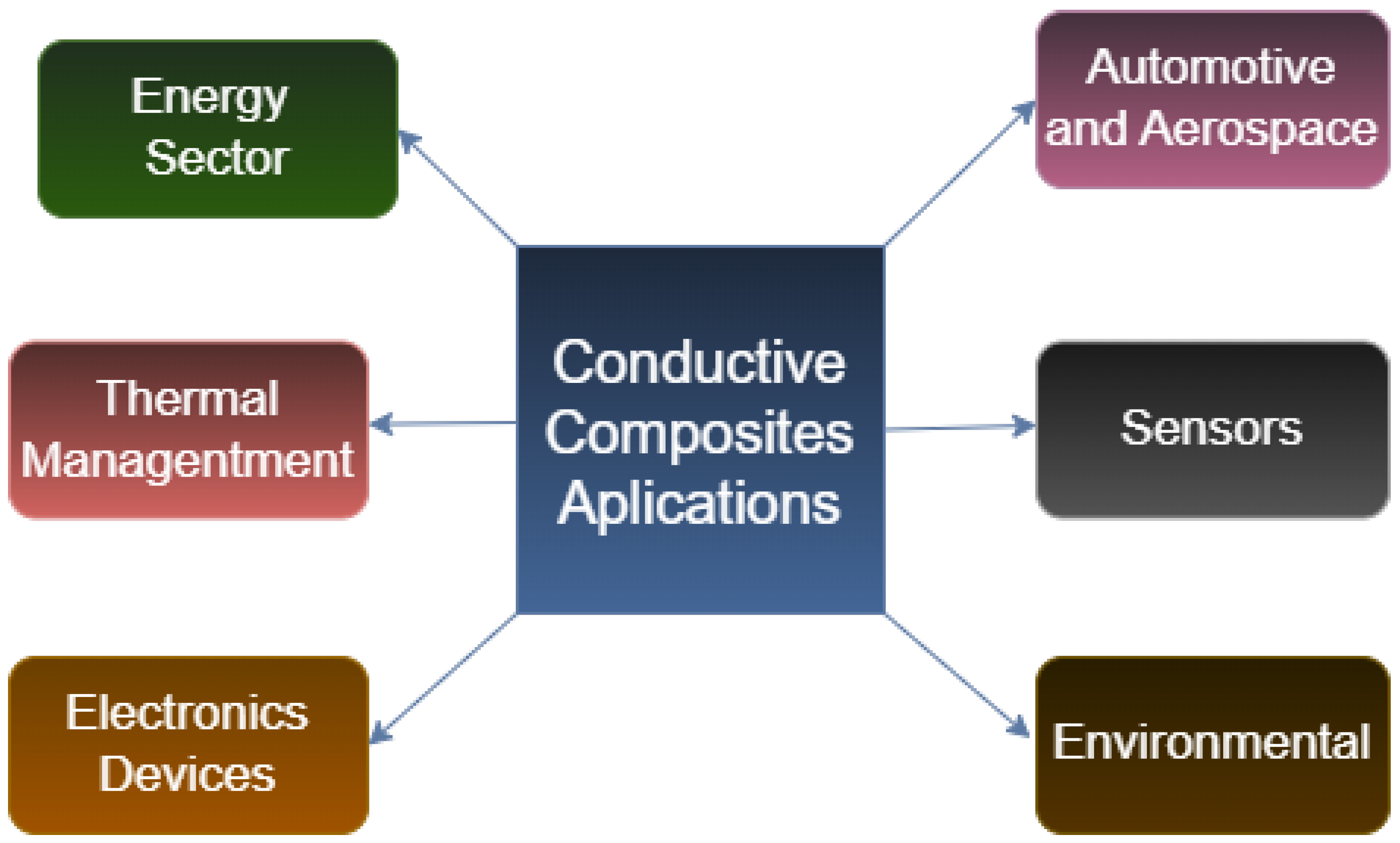
Figure 1. Diagram of the potential application areas of composites designed to exploit their electrical properties. SOURCE: Author.
Jcs 09 00438 g001
Figure 2. (a) Photomicrograph of a tungsten carbide-cobalt (WC-Co). (b) SEM image showing spherical carbon reinforcement particles in a synthetic rubber tire. SOURCE: [30].
Jcs 09 00438 g002
Figure 3. Macrostructures of different composites: (a) intermediate layers with corn starch (CS50); (b) intermediate layers with under-sintering (NSA); and (c) intermediate layers of B 4 C B N . Black layers: porous; gray layers: dense. SOURCE: [37].
Jcs 09 00438 g003
Figure 4. (a) Unidirectional, (b) cross-ply, (c) angle-ply, and (d) multidirectional. SOURCE: [30].
Jcs 09 00438 g004
Figure 5. Sandwich-type composite. Inner layer in honeycomb shape with adhesives to secure the upper and lower layers. SOURCE: [38].
Jcs 09 00438 g005
Figure 6. The white arrow showing carbon-coated silicon nanoparticles on the surface of the composite granules by SEM. SOURCE: [42].
Jcs 09 00438 g006
Figure 7. Representative figure of a simple cubic system as well as the restructuring of lattice parameters. SOURCE: [30].
Jcs 09 00438 g007
Figure 8. Schematic representation of typical band diagrams for (a) electrical conductors (e.g., metals), (b) semiconductors, and (c) insulators. Eg: band gap; BV: valence band; BC: conduction band; Ef: Fermi level at 298.15 K; The gray shading points to the presence of occupied states with charge transport capability. SOURCE: [49].
Jcs 09 00438 g008
Figure 9. Simplified diagram of electron energy states versus the interatomic separation of a cluster of 12 atoms. SOURCE: [30].
Jcs 09 00438 g009
Figure 10. Schematic representation of a band diagram for extrinsic semiconductors (a) n-type and (b) p-type compared to (c) an intrinsic one. BC: conduction band; BV: valence band; Ef: Fermi level of the intrinsic semiconductor; Efn: Fermi level of the n-type semiconductor; Efp: Fermi level of the p-type semiconductor; SBD: donor sub-band; SBA: acceptor sub-band. Schematic diagram represented at room temperature ( T 298.15 K). SOURCE: [49].
Jcs 09 00438 g010
Figure 11. Chemical illustration of the assembly process of the photothermal composite and deposition on a TE device. (a) Preparation of Ga particles. (b) Synthesis of MPI ink (TA–Fe3+–Ti4+). (c) The fabrication process of the LM-MPI composite. (d) MPI deposition over the LM particle layer. (e) The final architecture of the LM-MPI photothermal composite. (f) Illustration of the LM-MPI STEG under sunlight. SOURCE: [89].
Jcs 09 00438 g011
Figure 12. Characterization of Ga LM particles and MPI ink (TA-Fe3+-Ti4+). (a) SEM image of Ga LMs dispersion. (b) UV-vis absorption spectra of MPI, TA-Fe3+, TA-Ti4+, and pure TA. (c) Raman spectra of TA-Fe3+-Ti4+ ink and pure TA. XPS spectra of TA-Fe3+-Ti4+ ink. (d) Ti 2p core level. (e) Fe+2 3p3/2 core level. (f) Photograph of LM-MPI on TE device. (g) Cross-sectional SEM image of LM-MPI composite. (h) EDS analysis of LM-MPI cross-section. (i) Photograph of LM-MPI composite on flexible substrates. SOURCE: [89].
Jcs 09 00438 g012
Figure 13. Photothermal performance of composites. (a) Absorbance spectra of LM dispersion, LM-MPI, MPI, and Peltier in the 250–2000 nm wavelength range. (b) Reflectance of LM, LM-MPI, and MPI particles in the 2.0–25 μ m band. (c) Temperature profiles of LM, MPI, and LM-MPI composite on glass under 1 Sun irradiation. (d) Infrared thermal images of the glass coating under 1 Sun irradiation. (e) Temperature profiles of TE devices coated with LM, MPI, and LM-MPI composite under 1 Sun irradiation. (f) Infrared thermal images of the hot side of the TE under 1 Sun irradiation. SOURCE: [89].
Jcs 09 00438 g013
Figure 14. Solar thermoelectric performance of LM-MPI. (a) Open-circuit voltage (VOC) generated by the integrated STEG under 1 Sun irradiation. (b) Short-circuit current (ISC) generated by the embedded STEG under 1 Sun irradiation. (c) Comparison of power density output under 1 Sun irradiation. (d) VOC, (e) ISC, and (f) comparison of power density output under 2 Sun irradiation. Stability determination in cyclic tests: STEG performance exposed to 1 Sun irradiation in terms of (g) VOC and (h) ISC output. (i) Comparison of power density output with similar systems reported in the literature. SOURCE: [1,2,3,4,5,6,7,8,9,10,11,89].
Jcs 09 00438 g014
Figure 15. Electrical conductivity of Cu-Ni sintered composites with different wt.% of Y 2 O 3 . SOURCE: [98].
Jcs 09 00438 g015
Figure 16. Nyquist plot for data collected at 30 °C for LATP-0.1LASO composite sintered at 800 °C, 900 °C, and 1000 °C for 2 h. SOURCE: [104].
Jcs 09 00438 g016
Figure 17. Arrhenius plots of total ionic conductivity for LATP-×LASO composites sintered at 1000 °C for 2 h, 6 h, or 12 h. SOURCE: [104].
Jcs 09 00438 g017
Figure 18. Different polarization mechanisms. SOURCE: [125].
Jcs 09 00438 g018
Figure 19. Different polarization mechanisms. SOURCE: [125].
Jcs 09 00438 g019
Figure 20. Electronic bands and chemical structures illustrating (a) undoped, (b) polaron, (c) bipolaron, and (d) fully doped states of PPY. Source [139].
Jcs 09 00438 g020
Figure 21. Electronic band and chemical structure of PTh polymer with (a) p-type and (b) n-type doping. SOURCE: [139].
Jcs 09 00438 g021
Figure 22. (a) Graphical representation of intrinsically conductive polymers and (b) p-type doping process. SOURCE: Modified [143].
Jcs 09 00438 g022
Figure 23. Simplified scheme of a conjugated structure: a chain containing alternating single and double bonds. SOURCE: Modified [147].
Jcs 09 00438 g023
Figure 24. Current density versus voltage (CV) curves for (a) MnO2/S-PANI/P-RGO (4:1:2), (b) MnO2/S-PANI/P-RGO (2:1:1), and (c) MnO2/S-Aerogels PANI/P-RGO (2:2:1) at different scan rates; (d) curves of all MnO2/S-PANI/P-RGO samples at a scan rate of 10 mV/s. SOURCE: [160].
Jcs 09 00438 g024
Figure 25. Two-dimensional structure of the composite. Source: [172].
Jcs 09 00438 g025
Figure 26. Logarithmic graph of conductivity versus AC source frequency. Source: [172].
Jcs 09 00438 g026
Figure 27. Logarithmic graphs of dielectric constant and frequency for PVA/Cs with and without Ag NPs. (a) real part ( ε ) and (b) imaginary part ( ε ). Source: [172].
Jcs 09 00438 g027
Table 1. Electrical Applications.
CompositeApplicationsRefs.
MetallicVarious electronic components and household appliances[60,61]
CeramicElectrical insulators, sensors, and semiconductor devices[62,63]
PolymericLightweight electrical cables and insulators for electronic components[64,65]
Nano-reinforcementsCan improve electrical conductivity and other composite properties[66,67]
Table 2. Electrical conductivity with metal addition. Source: Modified from [79].
CompositeMetal ContentElectrical Conductivity (S/cm)Ref.
Pure Cu100 wt% 7 × 10 5 [80]
Pure Al100 wt% 3.54 × 10 5 [80]
Pure Ni100 wt% 1.43 × 10 5 [80]
Fe/EP/GO5 phr 8.07 × 10 4 [81]
Al/PS40 wt% 7.27 × 10 7 [82]
Cu/PS40 wt% 2.53 × 10 7 [83]
Cu/EP40 wt% 4.30 × 10 9 [84]
Ni/EP45 vol% 1.00 × 10 10 [85]
Cu/EP45 vol% 3.16 × 10 11 [85]
Cu/PVC45 vol% 6.31 × 10 12 [85]
Ni/PVC45 vol% 5.01 × 10 12 [85]
Cu/PVC18.7 wt% 4.76 × 10 13 [86]
Table 3. Different oxides for solid electrolyte applications. Source: Modified from [104].
TypeAbbreviationMolecular FormulaReference
PerovskiteLLTO L i 3 x L a 2 / 3 x T i O 3 [109,110]
GarnetLLZO L i 7 L a 3 Z r 2 O 12 [111,112,113]
NASICONLATP L i 1 + x A l x T i 2 x ( P O 4 ) 3 [114,115,116,117]
LISICON—— L i 3 + x P 1 x G e x O 4 [118,119]
Anti-Perovskite—— L i 2 + x O H 1 x C l [120,121]
Lithium-ion conducting oxide—— L i T a 2 O 8 [122,123,124]
Table 4. Conductive polymers. SOURCE: [139,140].
NamePolymerConductivity (S/cm)
PACJcs 09 00438 i001 10 3 to 10 6
PANIJcs 09 00438 i00210 to 10 3
PPyJcs 09 00438 i003600
PThJcs 09 00438 i004500
polyphenyleneJcs 09 00438 i005200
poly(p-phenylene vinylene)Jcs 09 00438 i0061
Disclaimer/Publisher’s Note: The statements, opinions and data contained in all publications are solely those of the individual author(s) and contributor(s) and not of MDPI and/or the editor(s). MDPI and/or the editor(s) disclaim responsibility for any injury to people or property resulting from any ideas, methods, instructions or products referred to in the content.