Abstract
Additive manufacturing (AM) has the potential to revolutionize the fabrication of continuous carbon fiber-reinforced polymer composites (CCFRPCs). Among AM techniques, direct ink writing (DIW) with ultraviolet (UV) curable resin shows promise for creating CCFRPCs with high manufacturing speed, high fiber volume fraction, and low energy consumption. However, issues such as incomplete curing and weak interfacial bonding, particularly in dense fiber bundles, limit the mechanical performance. This study addressed these challenges using pre-impregnated systems (PISs), which is a process developed to impregnate dry fiber bundles with partially cured resin before being used for DIW printing, to enhance resin-fiber adhesion and fiber–fiber bonding within fiber bundles. By optimizing resin viscosity and curing conditions in the PIS process, samples treated by PIS achieved improved mechanical properties. Tensile and bending tests revealed significant performance gains over non-PIS treated samples, with tensile stiffness increasing by at least 39% and bending stiffness by 45% in 3K fiber bundles. Tensile samples with thicker fiber bundles (6K and 12K) exhibited similar improvements. On the other hand, while all samples exhibit enhanced mechanical properties under bending deformation, the improvement of flexural stiffness and strength with thicker fiber bundles is shown to be less significant than those with 3K fiber bundles. Overall, composites made with PIS-treated fibers can enhance mechanical performance compared with those made with non-PIS-treated fibers, offering the scaling capability of printing thicker fiber bundles to reduce processing time while maintaining improved properties. It emphasizes the importance of refining the pre-processing strategies of large continuous fiber bundles in the AM process to achieve optimal mechanical properties.
1. Introduction
Additive manufacturing (AM) has the potential to revolutionize the fabrication of complex structures across various industries [1,2]. Unlike traditional subtractive manufacturing, AM builds components layer by layer, enabling complex geometries and material customization [3], offering many advantages such as reduced material waste, enhanced design flexibility, and rapid prototyping [4]. In addition to these benefits, the AM techniques—DIW and DLP—offer significantly lower energy requirements during fabrication. This is largely due to the absence of high-temperature ovens or autoclaves, as these processes typically operate at or near room temperature and utilize localized UV light for resin curing. Compared with thermal-based AM processes or conventional composite manufacturing methods, this substantially reduces energy consumption during both fiber impregnation and matrix consolidation [5]. However, it is important to note that many AM processes still require the use of support structures and post-processing—such as surface finishing, heat treatment, or support removal—to achieve the final part quality and mechanical integrity [4,6]. These benefits have established AM as a critical technology in fields ranging from aerospace to healthcare [7,8,9]. In recent years, the development of AM has expanded beyond single-material systems to include composites, particularly polymer matrix composites reinforced with continuous fibers [10,11]. The continuous carbon fiber-reinforced polymer composites (CCFRPCs) represent a groundbreaking class of materials, combining the lightweight and design versatility of polymers with the exceptional strength and stiffness of carbon fibers [12]. These materials are particularly well-suited for high-performance applications where mechanical efficiency and weight reduction are critical. Real-world examples include structural components in aerospace engineering—such as aircraft wing spars, fuselage skin panels, and internal frames—where weight savings directly translate to fuel efficiency and payload capacity [7]. In the automotive sector, CCFRPCs are increasingly used in chassis frames, suspension control arms, and crash structures, offering improved energy absorption and rigidity without compromising vehicle weight [13].
Integrating 3D printing and composite manufacturing offers unique benefits compared with traditional composite fabrication methods, such as autoclaving and hand layup [14]. Firstly, 3D printing enables localized reinforcement, allowing carbon fibers to be precisely deposited in areas subjected to high stresses [15]. This tailored material placement enhances the mechanical efficiency of structures [16]. Secondly, AM stimulates the production of complex, topology-optimized geometries, which are challenging or impossible to achieve using conventional approaches [17,18]. Additionally, it minimizes waste and reduces production times, making it a sustainable option for composite fabrication [19].
Fused filament fabrication (FFF) is a widely used technique where thermoplastic filaments are heated and extruded through a nozzle to build parts layer by layer [20]. For CCFRPC fabrication, the process involves the co-extrusion of a polymer filament and continuous carbon fiber [21]. This technique is favored for its simplicity and scalability [22]. However, the challenge lies in achieving uniform fiber alignment and strong interfacial bonding between the fiber and the polymer matrix, which are critical for enhancing mechanical properties [23]. Ye et al. addressed key challenges associated with material viscosity and fiber feeding by embedding continuous carbon fiber into thermoplastic polyimide during printing [16]. Their method not only improves the printing success rate but also significantly enhances the interfacial bonding strength between the carbon fiber and the polymer matrix. This approach has been widely adopted for fabricating CCFRPCs by embedding continuous carbon fibers into thermoplastic during the printing process [24]. Several studies have advanced the understanding of pre-impregnation techniques for thermoplastic composites in additive manufacturing. Shin et al. [25] demonstrated a reactive processing approach using partially polymerized polymethyl methacrylate (PMMA) with carbon fiber reinforcement, enabling low-temperature and low-pressure consolidation with minimal porosity. Wang et al. [26] developed continuous carbon fiber-reinforced polylactic acid (PLA) prepreg filaments optimized for independent extrusion, achieving significant mechanical improvements with a tensile strength of 620 MPa in printed parts. Garofalo and Walczyk [27] introduced an in situ pre-impregnator system for thermoplastic composites, improving fiber impregnation and reducing void content through pultrusion-based methods. The effects of heat and moisture on carbon fiber-reinforced polyamide-6 prepregs have also been investigated to highlight the susceptibility of mechanical properties to environmental conditions [28,29].
Direct ink writing (DIW) employs a viscous resin or ink, typically containing carbon fibers or other fillers for composite AM [30]. DIW provides precise control over fiber orientation, making it an excellent candidate for manufacturing highly tailored composites [31]. Compared with other additive manufacturing techniques, such as FFF and SLA, DIW offers unique advantages in the fabrication of continuous fiber-reinforced composites. While FFF is favored for its simplicity and scalability, it often struggles with achieving effective fiber impregnation due to the rapid solidification of thermoplastic materials during deposition. SLA, on the other hand, provides high-resolution features but is limited in directly integrating continuous fibers due to constraints in resin flow and curing kinetics. DIW bridges this gap by enabling continuous fiber deposition with fine control over placement and alignment, along with the ability to tune resin viscosity for better fiber wetting. These characteristics make DIW particularly well-suited for producing high-performance composites with controlled microstructures and mechanical anisotropy. Recent studies have highlighted the potential of DIW in processing thermosetting polymer composites reinforced with continuous fibers. For example, research employing 3K continuous carbon fibers combined with a phenolic epoxy resin demonstrates the ability of DIW to enhance mechanical properties through controlled fiber alignment and distribution [32]. The use of a curing agent, such as 2-ethyl-4-methylimidazole, alongside a low-temperature extrusion process allows for the successful impregnation of fibers and optimal resin viscosity during printing. Such advancements underscore the DIW process’s suitability for creating high-performance materials with precise fiber orientation and predictable structural properties [33].
Furthermore, innovations in DIW have extended to hybrid composite systems. For example, Lewicki et al. [34] demonstrated the use of shear forces to align short carbon fibers within a bisphenol-F epoxy resin matrix, enabling the creation of composites with tailored and predictable mechanical properties. Similar approaches have been adapted for ceramic reinforcement, such as boron nitride-reinforced ceramic composites, demonstrating the versatility of DIW in fabricating complex and multifunctional structures [35]. DIW and Digital Light Processing (DLP) processes complement each other in the fabrication of high-performance resin-fiber composites. DIW is particularly effective in depositing continuous fibers, ensuring precise placement of fiber [36,37]. Meanwhile, DLP adds another layer of resin, embedding the fibers through its high-resolution curing process. The integrated process of DIW for fiber placement and DLP for matrix curing creates an innovative way to 3D print high-resolution, fully dense CCFRPC. When both processes use compatible photo-sensitive resins, their chemical and physical properties align together, minimizing interfacial defects and enhancing cohesive material behavior throughout the composite structure. Together, DIW and DLP enable precise control over fiber placement, resin infiltration, and curing, resulting in improved composite performance. The resin remains in a liquid state before curing [38], which can infiltrate gaps between the DIW-printed continuous fibers, promoting the most optimal adhesion and load transfer at the interfaces. Moreover, the choice of photo-sensitive resin over epoxy as the thermoset material for DIW offers an additional advantage: compatibility with the DLP matrix resin [39]. When the same photo-sensitive resin is used for both the DIW and DLP processes, the chemical and physical properties of the materials align, leading to optimal bonding results [40]. It was found that adding nano clays to phenolic resin in the pre-impregnation of continuous carbon fiber can enhance the mechanical properties [41]. This integration minimizes the risk of interfacial defects and ensures cohesive material behavior throughout the composite structure.
Despite significant advancements in resin-based 3D printing for the fabrication of CCFRPCs, challenges remain in optimizing the mechanical properties of DIW-printed fiber bundles with ultraviolet (UV) sensitive resin. These challenges of improving fiber–fiber bounding become particularly pronounced for fiber bundles with a high number of fibers, such as 12K fiber tows. Existing research was mainly focusing on low-density fiber bundles such as 1K and 3K fibers. Further investigation is needed to understand and address the limitations of resin curing inside thick fiber bundles. The advantage of printing higher-density fiber bundles, such as 12K, is that it can offer significant time efficiency, as a single 12K fiber bundle contains the equivalent fiber content of twelve 1K bundles. This approach reduces printing time and processing complexity, making it a practical solution for scaling up production. However, it is more difficult to uniformly impregnate resin with each single fiber in higher-density fiber bundles. This research developed a pre-impregnated system (PIS) to improve the impregnation and ultimately enhance the mechanical stiffness and strength of fiber-reinforced photo-sensitive polymers. Addressing these challenges is essential for unlocking the full potential of DIW-printed composites for high-performance applications. This research investigated the optimal combination of PIS resin systems to achieve improved material properties. By comparing PIS-treated CCFRPCs with non-PIS-treated CCFRPCs as a control group, this work seeks to establish a scalable, efficient pathway for producing high-performance composites using 3D printing.
2. Materials and Methods
2.1. PIS-Based Fiber Processes
This PIS process involves multiple resin impregnation and curing steps to improve resin penetration and bonding, as shown in Figure 1. The UV resin used is Phrozen Aqua Clear Resin (Phrozen Technology, Taiwan, China), selected for its moderate viscosity cPs), excellent UV transparency, and reliable curing performance under 405 nm light. In the first step, fibers are drawn from spools through an initial resin vat and then pass through a flat curing chamber equipped with 30 UV lights arranged in two sets—15 above and 15 below the chamber. Each UV LED emits at a wavelength of 405 nm with an intensity of approximately applied to the fiber bundle. Each light in this chamber operates at 10.2 V and 13.2 mA, providing controlled partial curing. This configuration ensures that the fibers are cured in a flat orientation, maximizing the surface area exposed to the resin and allowing more fibers within the bundle to be impregnated and partially cured. The goal of this stage is to achieve an intermediate cure level, where the resin remains pliable enough for the flattened fiber bundle to be reshaped later in the process.
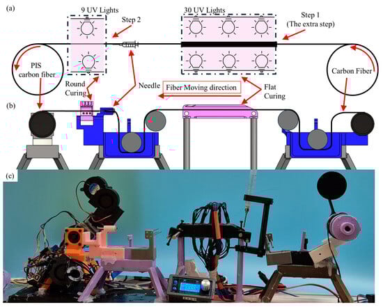
Figure 1.
(a) Schematic, (b) CAD design, and (c) machine setup of the pre-impregnation process to prepreg continuous fibers with photo-sensitive resin.
After the initial curing stage, the fibers are drawn through a second resin vat for re-impregnation, followed by a rounded curing chamber. Here, the fibers undergo a second curing step using 12 V and 20 mA per light, with nine lights in total. Each UV LED emits at a wavelength of 405 nm with an intensity of approximately applied to the fiber bundle. This second curing chamber also features a needle and nozzle mechanism to reshape the fiber bundle from a flat to a round cross-section, a geometry more suitable for DIW printing. The intermediate curing achieved in the first chamber is critical for this reshaping step, as insufficient curing would lead to structural instability, while over-curing would prevent the fiber bundle from conforming to the desired rounded shape.
The process settings were further refined to account for the size of the fiber bundle. Thicker bundles, such as 12K tows, require slower movement speeds, 5 mm/s (3K), 4 mm/s (6K), 3 mm/s (12K), from the stepper motor to ensure sufficient exposure time under the UV lights in each curing chamber. This adjustment compensates for the increased volume of resin required to penetrate the bundle and ensures consistent partial and full curing.
2.2. DLP- DIW Printer Setup
The 3D printing system utilized in this research is an in-house hybrid DLP-DIW printer, which combines DLP for resin curing with DIW for continuous fiber deposition [42]. Its design allows the integration of the two printing technologies, enabling the fabrication of complex geometries with tailored fiber reinforcement. The printer comprises a DLP projector for layer-by-layer photopolymerization and a DIW extrusion system equipped with a 3 mL syringe for precise placement of continuous fibers; the printing process is shown in Figure 2c. The resin vat, located beneath the printing platform, holds photo-sensitive resin that cures upon exposure to 405 nm UV light. The DIW system is used to deposit continuous carbon fibers (CST The Composites Store, Inc., Los Angeles, CA, USA), which are in-nuzzle impregnation with high-viscosity resin mixed with Al2O3 (XFnano, Inc., Nanjing, China). The nozzle diameter is selected based on the fiber bundle size: a 12-gauge nozzle (2.16 mm inner diameter) for 12K bundles, 15-gauge (1.37 mm) for 6K, and 17-gauge (1.07 mm) for 3K bundles. To ensure proper curing, three optical fibers deliver targeted UV light to the deposition area, dynamically controlled to prevent premature curing ahead of the nozzle. The printer’s motion is governed using a modified microcontroller that synchronizes the movement of the printing head and the activation of the optical fibers. This setup ensures precise placement and efficient curing of the resin and fibers, resulting in mechanically robust, continuous-fiber-reinforced structures.
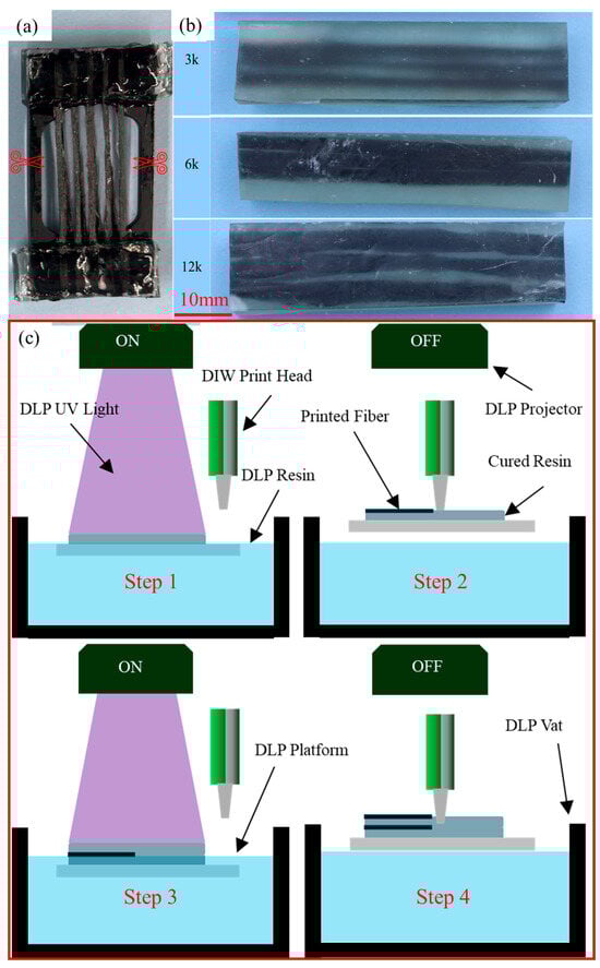
Figure 2.
(a) Samples made for PIS-treated fiber tensile test, (b) DIW-DLP printed CCFRPCs with PIS-treated fiber for tensile and bending tests (3K, 6K, 12K from top to bottom), and (c) DIW-DLP 3D printing process.
2.3. Samples Fabrication
2.3.1. Fiber-Only Samples
The fiber-only sample is to test the mechanical properties of PIS-treated carbon fiber compared with non-PIS-treated carbon fiber. It can reveal the mechanical behavior of fiber with impregnation resin only and exclude the influence of the resin matrix. To prepare fiber-only samples for tensile testing, the fibers were manually wrapped around a hollow block and secured to the jaws of a tensile testing machine. The PIS-treated samples included resin on the fiber cores and surfaces introduced during the multiple impregnation and curing steps of the PIS process. In contrast, the non-PIS-treated samples only had resin applied from the printing nozzle, resulting in minimal resin coverage on the fiber surfaces. This preparation ensured that the tensile testing isolated the mechanical properties of the fibers themselves, independent of a fully embedded resin matrix. After securing the fibers, a cutter was used to carefully remove the edges from the hollow block, leaving only the fiber segments for testing. The samples were then tested using a standard testing machine to establish baseline mechanical properties, as shown in Figure 2a.
Fiber-only samples are essential for evaluating the intrinsic mechanical performance of the treated fibers without the confounding influence of a resin matrix but also offer insights into how PIS treatment parameters, such as fiber bundle size and resin viscosity, influence the mechanical performance of carbon fiber bundles. By isolating the fibers, the effects of the PIS treatment on fiber strength can be directly assessed, allowing observed improvements to be attributed solely to the treatment process rather than to fiber–matrix interactions.
2.3.2. DLP-DIW Samples
To evaluate the mechanical performance of DLP-DIW composite samples and to assess the effectiveness of the PIS-treated fibers within a resin matrix, two types of DLP-DIW composite samples were fabricated for mechanical testing: tensile and bending specimens, as shown in Figure 2b. These tests were designed to simulate practical loading conditions and to quantify how the PIS process improves resin-fiber bonding and the mechanical properties of the composite material. By subjecting the samples to tensile and bending tests, this study aimed to determine the extent to which the PIS-treated fibers enhance stiffness and strength compared with their non-PIS-treated counterparts.
Tensile Test Samples (L, W, H: 60 mm, 10 mm, 3 mm): These samples consisted of a single layer of fibers containing three continuous fiber bundles embedded in a photopolymer resin matrix. The resin thickness above and below the fiber bundles was maintained to be equal, ensuring uniform stress distribution during tensile testing.
Bending Test Samples (L, W, H: 60 mm, 10 mm, 8 mm): For bending tests, the layout of the fiber bundles was identical to that of the tensile samples, but the resin matrix thickness varied. The resin layer above the fiber bundles was significantly thicker than the layer below. The fibers were under tensile and shear stress during the bending test. The shear stress could cause sliding of fiber if the bonding between fiber and matrix was not strong.
3. Results
The tensile and bending tests were conducted by MTS C43 mechanical tester (MTS Systems, Eden Prairie, MN, USA) with a 30 kN load cell. The testing speed was set to 1 mm/min for the quasi-static testing. The gauge length of fiber-only samples and tensile test samples is 20 mm. The strain of the tensile test is measured by LX Laser Extensometers (MTS Systems, Eden Prairie, MN, USA).
3.1. Pre-Impregnation Steps Investigation
In the PIS workflow, Step 1 involves flattening the fiber bundles and ensuring the resin penetrates thoroughly into each fiber within the bundle. Subsequently, Step 2 involves consolidating the material to produce the final PIS process. A comparison between composite samples made with one-step (without Step-1 in Figure 1a) PIS-treated fiber and two-step treated (as in Figure 1a) fiber was made to test the effectiveness of flattening the fiber bundles. The absence of this initial step in the one-step process often results in incomplete resin impregnation and uneven fiber wetting, particularly for tightly packed fiber bundles.
Bending samples introduced in Section 2.3.2 were printed and tested to measure flexural stiffness. The importance of the two-step PIS process is highlighted in Figure 3a, which shows the bending test results for 12K fiber bundles prepared using a simplified one-step PIS process. The one-step process lacks the flattening curing chamber included in the two-step design. The flexural modulus of the one-step PIS samples is approximately 25% lower than that of the two-step PIS samples. This reduction in performance is attributed to the absence of the flattening step, which limits resin penetration and curing consistency within the fiber bundle. The unoptimized one-step process results in weaker fiber-matrix bonding and an uneven distribution of stress under flexural loads, highlighting the critical role of the two-step design in achieving improved mechanical performance. It was also shown in Figure 3b that for low-density fiber bundles (3K), the improvement of two-step impregnation is not as significant as high-density fiber bundles (6K and 12K), which indicated that the two-step process could improve the under-infiltration of resin in high-density fiber bundles. By systematically optimizing parameters such as curing intensity, resin viscosity, fiber bundle size, and motor speed, the two-step PIS process ensures improved resin impregnation, consistent curing, and enhanced resin-fiber bonding.
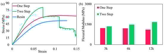
Figure 3.
(a) The bending test results comparison of one and two-step(s) PIS process on 12K fiber bundles. (b) Flexural Modulus of 3, 6, and 12K bundles with one- and two-step(s) PIS process.
3.2. Fiber-Only Tensile Test
The testing results of fiber-only tensile samples are shown in Figure 4. The results demonstrated clear distinctions in tensile behavior between non-PIS-treated and PIS-treated fibers, as well as the impact of resin viscosity on the strength of PIS-treated bundles. As the fiber bundle size increases, the gap between PIS-treated and non-PIS-treated fibers’ peak load increases.
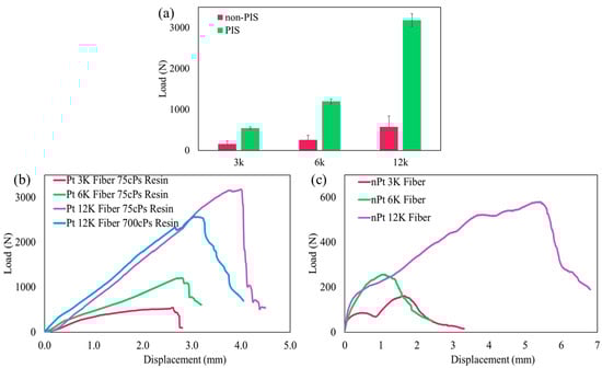
Figure 4.
(a) PIS-treated and non-PIS-treated fiber peak load plot of 3K, 6K, and 12K fiber. (b) Tensile test results comparison of fibers after PIS treatment on bundle size of 3K, 6K, 12K, and 12K but higher viscosity resin. (c) Tensile test results comparison of without PIS treatment on bundle size of 3, 6K, 12K.
3.2.1. Different Bundle Size Fiber
The peak load values for non-PIS-treated and PIS-treated fiber bundles are shown in Figure 4a. For all fiber sizes, PIS-treated samples exhibited significantly higher peak loads than their non-PIS-treated counterparts. Specifically, the 3K, 6K, and 12K PIS-treated samples achieved peak loads of approximately 655.7 N, 1297.3 N, and 3158.9 N, respectively. These values increased significantly with the application of PIS, highlighting the role of pre-impregnation in enhancing fiber–fiber bundle bonding. The trend also indicates that thicker bundles, while naturally able to carry greater loads due to their higher fiber content, benefit more substantially from the PIS process.
The load-displacement behavior of the tested fiber bundles, shown in Figure 4b,c, further underscores the performance improvements afforded by PIS. The PIS-treated samples exhibited steeper slopes as the bundle size increased in the load-displacement curves, reflecting greater stiffness and more efficient load transfer.
3.2.2. Under Different Viscosity of Resin
The influence of PIS resin viscosity on the tensile performance of 12K fiber bundles is presented in Figure 4b. The resin for the PIS process is Phrozen Aqua Clear Resin because of its lower viscosity (75 cps at 25 °C).
As shown in Figure 4b, the lower-viscosity resin results in a noticeably higher peak load in the 12K fiber bundles. This improvement is attributed to the improved ability of the low-viscosity resin to penetrate densely packed fibers, achieving better impregnation and more uniform resin distribution throughout the bundle. In contrast, the high-viscosity resin shows limited penetration, resulting in incomplete wetting and weaker fiber–fiber bonding, especially toward the core of the bundle.
While stiffness (slope of the curve) does not vary significantly between the two resins, the differences in peak load clearly reflect the impact of resin viscosity on load-bearing capacity. These results reinforce that optimizing resin viscosity is crucial for maximizing the effectiveness of the PIS process in high-density fiber systems.
The control group with higher viscosity resin is Siraya Tech Blu clear (Siraya Tech, San Gabriel, CA, USA) with a higher viscosity (700 cps at 25 °C). Samples impregnated with lower-viscosity resins consistently exhibited higher peak loads compared with those using higher-viscosity resins. At the same time, the stiffness did not show much difference samples made with low-viscosity and high-viscosity resins. The results indicated that the low viscosity resin can better penetrate the fiber bundles than high viscosity resin and improve the bonding between fibers and resins.
3.3. Tensile and Bending Test for DLP- DIW Made Samples
The standard deviation percentages (Std %) reported in Table 1 provide important insight into the consistency and repeatability of mechanical performance across different sample types and fiber bundle sizes. In both tensile and bending tests, PIS-treated samples consistently exhibited lower variation compared with non-PIS-treated samples, indicating more stable and uniform processing outcomes. For example, in tensile tests, the Std % for PIS-treated samples remained below 7% across all bundle sizes, while the untreated groups showed notably higher variation, particularly in the 12K group (25.12%). A similar trend was observed in bending, where the untreated 12K samples exhibited the highest variability (42.33%), suggesting less consistent resin infiltration and interfacial bonding. In contrast, PIS-treated samples maintained more controlled mechanical responses, even with thicker fiber bundles. These differences in statistical variation highlight the improved process control and repeatability achieved through the PIS method, establishing a reliable basis for evaluating the mechanical performance presented in the following sections.

Table 1.
Average tensile and bending modulus of PIS-treated and non-PIS-treated composite samples across different fiber bundle sizes, with corresponding standard deviation percentages (Std %) indicating variation in mechanical performance.
3.3.1. Tensile Test
The tensile test results provided a detailed assessment of the stiffness and strength of PIS-treated and non-PIS-treated fiber bundles, highlighting the influence of fiber bundle size and pre-impregnation on mechanical performance. Figure 5 summarizes the strain-stress behavior and Young’s modulus for both PIS-treated and non-PIS-treated samples. Figure 5a presents the strain-stress curves for 3K, 6K, and 12K fiber bundles with and without PIS treatment. The slopes of the strain-stress curves, which correspond to the stiffness of the samples, are significantly steeper for PIS-treated samples compared to non-PIS-treated samples of the same bundle size. This indicates that PIS treatment greatly enhances the fiber-matrix bonding, resulting in more efficient load transfer and higher stiffness. For non-PIS-treated samples, the non-ideal fiber-matrix interface leads to sliding between the fiber bundle and matrix, reducing the overall stiffness of the material. Figure 5b compares Young’s modulus of PIS-treated and non-PIS-treated samples across different bundle sizes. The PIS-treated samples have 253% (3K), 52% (6K), and 80% (12K) higher Young’s modulus than non-PIS-treated samples. This consistency demonstrates the effectiveness of the PIS process in achieving uniform fiber-matrix bonding, regardless of bundle size. The difference between non-PIS-treated and PIS-treated samples is more significant for 12K fiber bundles than 3K and 6K fiber bundles, which is attributed to incomplete resin penetration and weaker interfacial bonding, particularly in the core of the bundle where fibers remain largely unbonded.
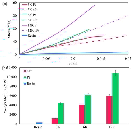
Figure 5.
(a) The strain-stress curve of tensile test of fiber samples made by 3, 6, and 12K (non-)PIS-treated fiber. (b) The bar chart of Young’s modulus of 3, 6, and 12K (non-)PIS-treated fiber.
3.3.2. Bending Test
The bending tests provided critical insights into the performance of composites made with PIS-treated and non-PIS-treated fiber bundles under flexural loads. Figure 6a highlights the bending behavior of PIS-treated and non-PIS-treated fiber samples with different fiber bundle sizes (3K, 6K, and 12K). For the 12K fiber samples, a sequential failure mode is observed during the bending test. The flexural modulus comparison for PIS-treated and non-PIS-treated fiber samples is shown in Figure 6b. PIS-treated samples consistently outperform non-PIS-treated samples across all bundle sizes, demonstrating the effectiveness of the pre-impregnation process. The PIS-treated samples have 15% (3K), 16% (6K), and 42% (12K) higher Young’s modulus than non-PIS-treated samples. However, the flexural modulus did not increase proportionally to the fiber bundle size increase. Thicker bundles, such as the 6K and 12K samples, exhibit greater deviations due to the challenges of achieving uniform curing throughout the bundle, which restricted the improvement of the flexural properties of the composites.
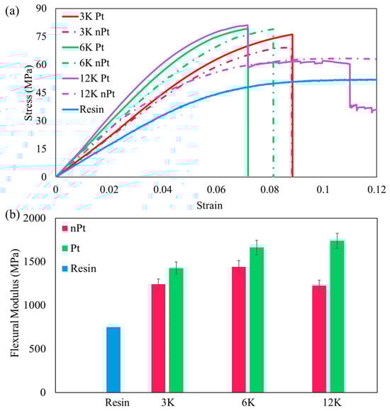
Figure 6.
(a) The strain-stress curve of bending test of fiber samples made by 3, 6, and 12K (non-)PIS-treated fiber. (b) The bar chart of flexural modulus of 3, 6, and 12K (non-)PIS-treated fiber (Pt refers to PIS-treated, and nPt refers to non-PIS-treated in the figures).
3.4. Failure Mode Analysis
To further investigate the resin-fiber bonding behavior, post-fracture analysis was conducted on both PIS-treated and non-PIS-treated samples using optical microscopy and scanning electron microscopy (SEM). Representative images are presented in Figure 7a, the zoom in view of the broken fiber bundle (white) and the pulled-out section (black).
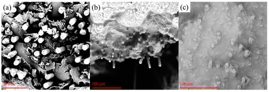
Figure 7.
(a) The overview of SEM inspection of the failure study, (b) non-PIS-treated samples, and (c) PIS-treated samples.
In non-PIS-treated samples, as shown in Figure 7b, the fracture surfaces exhibited extensive fiber pull-out, resin cracking, and visible voids around the fibers. This indicates poor interfacial bonding, allowing fibers to slide or separate from the resin under load.
By contrast, the PIS-treated samples (Figure 7c) showed clean fracture lines with fibers well embedded in the resin. Very few fibers exhibited pull-out, and the surrounding matrix appeared to be tightly bound to the fiber surfaces, suggesting stronger adhesion and improved load transfer. These observations are consistent with the higher stiffness and strength values measured in tensile and bending tests.
The microstructural differences in failure modes confirm that the PIS process enhances impregnation and bonding quality, particularly for high-density fiber bundles.
4. Discussion
PIS has significantly improved the mechanical strength of CCFRPCs. However, the extent of these enhancements is influenced by several key factors, including the PIS process (one-step or two-step), the number of fibers in the bundles, and the choice of PIS resin. The findings of this study indicate that a two-step PIS process and the use of low-viscosity resins result in much better material performance. The tensile tests of fiber-only samples highlight the improvements achieved through PIS treatment, with PIS-treated samples exhibiting higher stiffness, higher peak loads, and more cohesive failure mechanisms. The marked increase in peak load for 12K bundles is particularly noteworthy, as it indicates enhanced fiber–fiber bonding in addition to improved fiber-matrix bonding. This stronger fiber–fiber interaction reduces sliding and load redistribution within the bundle, enabling the composite to sustain higher loads before failure. In a two-step PIS process, the initial curing stage can flatten the individual carbon fibers, transforming their cross-section from a circular shape into a more flattened sheet before going into the curing chamber. This increased surface area enhances fiber exposure to UV light, facilitating better curing of the resin around the fibers. In contrast, in a one-step process, the limited surface exposure and UV penetration result in incomplete curing, particularly at the center of the fiber bundles. This is due to the opacity of carbon fibers, which prevents UV light from penetrating deep into the bundle. As the size of the fiber bundles increases, the challenges of achieving complete curing and impregnation become more pronounced. Thicker bundles have a higher proportion of fibers at their center that remain unexposed to UV light during the curing process. This results in a hard outer shell of cured resin surrounding a soft, uncured core. Lower-viscosity PIS resins further improve impregnation by readily infiltrating tightly packed fibers, enhancing fiber-matrix and fiber–fiber bonding. These benefits are particularly evident in 12K fiber bundles, where low-viscosity resins reduce uncured regions and increase tensile strength and stiffness.
In DIW-DLP composite samples, the sliding between individual fibers within the bundle plays a significant role in the discrepancy between theoretical and experimental mechanical performance. This sliding is exacerbated in non-PIS-treated samples, where the uncured core allows fibers to move independently under load, leading to inefficient load transfer. Conversely, PIS-treated samples exhibit reduced fiber sliding due to the improved interfacial bonding within the bundle, bringing the experimental results closer to theoretical predictions. In ideal cases, the fibers should break cleanly in conjunction with the surrounding matrix, maintaining integrity across the fracture plane. However, the results deviate from this ideal scenario, particularly as fiber bundle size increases. This is attributed to the uncured core within thicker bundles, where inadequate UV penetration during the PIS process results in weaker resin-fiber bonding. Under load, these uncured fibers are less likely to fail cohesively with the matrix, leading to sliding or pull-out instead of clean breakage. This phenomenon is particularly evident in non-PIS-treated samples, where the resin does not sufficiently penetrate the fiber bundle, leaving the core fibers minimally bonded and more prone to remaining intact after fracture. During the tensile test, PIS-treated samples consistently exhibit fewer unbroken fibers compared with non-PIS-treated samples, indicating that the pre-impregnation process significantly enhances fiber-matrix bonding, as shown in Figure 8. The improved adhesion achieved through the PIS process results in more cohesive failure, where fibers break in unison with the matrix. This finding aligns with the stress-strain test results, which show higher ultimate strengths and moduli for PIS-treated samples compared with their non-PIS-treated counterparts.
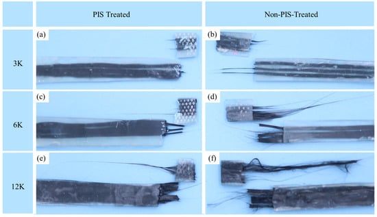
Figure 8.
The tensile failure samples: (a) 3K PIS-treated fiber, (b) 3K non-PIS-treated fiber, (c) 6K PIS-treated fiber, (d) 6K non-PIS-treated fiber, (e) 12K PIS-treated fiber, and (f) 12K non-PIS-treated fiber.
In tensile testing, the loading is primarily uniaxial, and the clamping force from the test jaws ensures that the fiber bundles remain tightly gripped. This can prevent significant sliding between the fibers within the bundle and between the bundle and the matrix, mitigating the effects of the uncured core. In bending tests, however, the loading conditions are more complex, involving a combination of tensile, compressive, and shear stresses. This non-uniform stress distribution can exacerbate the effects of incomplete curing in the core of thicker fiber bundles. In the bending test results shown in Figure 9, both PIS-treated and non-PIS-treated samples exhibited more unbroken fibers than their tensile counterparts, regardless of the bundle density. The uncured fibers within the bundle may slide or pull out under load as they are less effectively bonded to the matrix. This led to more unbroken fibers after fracture in bending tests, especially in samples with thicker fiber bundles. This phenomenon arose from the complex loading environment in three-point bending tests, which imposes a combination of axial, compressive, and shear stresses. As a result, tensile tests may not fully reveal the impact of incomplete curing.
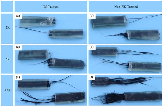
Figure 9.
The bending failure samples: (a) 3K PIS-treated fiber, (b) 3K non-PIS-treated fiber, (c) 6K PIS-treated fiber, (d) 6K non-PIS-treated fiber, (e) 12K PIS-treated fiber, and (f) 12K non-PIS-treated fiber.
As the fiber bundle density increases, post-test inspection reveals a clear distinction between PIS-treated and non-PIS-treated samples. In high-density bundles, the uncured fibers in PIS-treated samples are thinner and predominantly aligned along the axial direction. This alignment is attributed to the bundling effect of the PIS process, which ensures that more fibers are impregnated and cured, reducing lateral sliding. In contrast, non-PIS-treated samples exhibit thicker uncured fibers that are misaligned and point in multiple directions. This lack of alignment further weakens the composite by increasing the likelihood of fiber sliding and inconsistent load transfer.
A cross-sectional analysis of the samples, shown in Figure 10a,b, confirms the presence of a soft core in high-density fiber bundles, characterized by its darker color and reflective wet appearance compared with the solidified resin shell. This contrast shows that the core retains a degree of unreacted or partially cured resin, in contrast to the outer shell, which appears more rigid and solidified. The formation of this core-shell structure likely results from differential resin infiltration and curing dynamics, where the outer layers experience complete polymerization due to increased exposure to UV lights while the inner regions remain less fully cured. Such a phenomenon can significantly influence the mechanical properties of the composite.
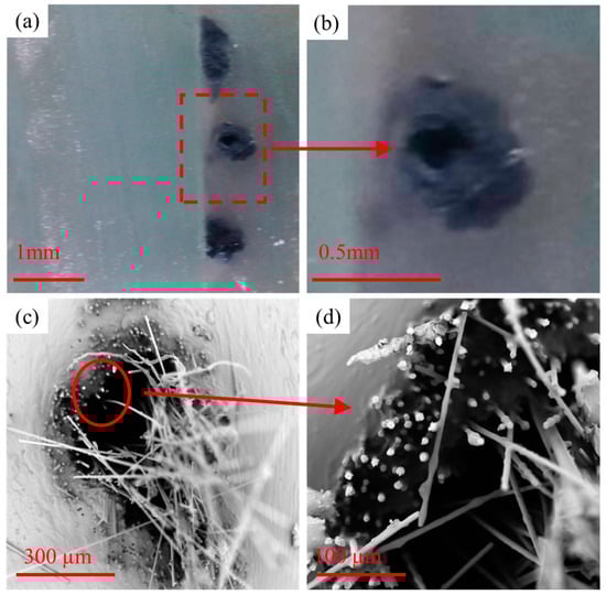
Figure 10.
Uncured 12K fibers pulled out from non-PIS-treated samples after (a) the cross-sectional cut of samples with uncured soft core fiber bundle, (b) zoom-in view of (a), and (c) SEM inspection of the fiber bundle failure model, (d) zoom-in view of (c).
Figure 10c,d presents SEM images that further elucidate the failure mechanisms associated with insufficient curing in non-PIS-treated samples. In these images, regions of bright contrast correspond to fractured fibers, indicating sites of tensile failure, while the darker regions represent areas where fibers were pulled out from the matrix—an outcome typically associated with poor interfacial bonding due to inadequate resin curing. The prevalence of these dark zones suggests significant regions within the bundle where the resin did not fully cure, thereby failing to anchor the fibers effectively.
This pull-out behavior is symptomatic of weak fiber-matrix adhesion, which compromises load transfer efficiency and contributes to premature failure under stress. In contrast to the PIS-treated counterparts, which demonstrate more cohesive failure modes and cleaner fracture surfaces, the non-PIS-treated samples reveal a heterogeneous failure profile marked by fiber debonding and matrix separation. The enlarged view in Figure 10d clearly illustrates the distinction between the clean break surfaces of fully cured fibers and the smeared or ragged regions surrounding the pulled-out fibers.
5. Conclusions
This study highlights the significant advantages of PIS in the fabrication of CCFRPC via AM. The results demonstrated that PIS treatment enhances the mechanical performance of fiber bundles by improving fiber-matrix and fiber–fiber bonding. Specifically, the two-step PIS process, combined with low-viscosity resin, ensured better resin penetration and curing uniformity, addressing challenges such as incomplete curing and weak interfaces in thicker fiber bundles. Tensile and bending tests consistently showed improved performance for PIS-treated samples compared with non-PIS-treated samples. In tensile tests, PIS-treated fibers exhibited significantly higher stiffness and minimal deviations between theoretical and experimental results, regardless of bundle size. Conversely, non-PIS-treated samples displayed increasing performance losses with thicker bundles, highlighting the limitations of resin penetration during the printing process alone. Bending tests revealed more complex failure modes, particularly in thicker bundles, where the hard shell-soft core structure of incompletely cured fibers led to a sequential failure and greater deviations from theoretical predictions.
These findings pointed out the importance of optimizing PIS parameters, including resin viscosity, curing design, and bundle size, to achieve the desired mechanical properties. While PIS-treated 3K and 6K bundles showed near-ideal performance, challenges remained in scaling up to thicker bundles such as 12K, where fiber-matrix and fiber–fiber bonding must be further improved to minimize sliding and ensure cohesive failure under complex loading conditions.
This study confirms that a two-step PIS, combined with low-viscosity resin, significantly enhances the mechanical performance of CCFRPCs produced via additive manufacturing. Improved resin infiltration and curing uniformity led to higher stiffness, strength, and more cohesive failure behavior, especially in high-density bundles. These findings were supported by mechanical testing, statistical analysis, and SEM imaging. However, limitations remain, including restricted UV penetration in thick bundles and the use of a single resin system. Future work will explore advanced curing strategies, optimized resin formulations, in situ monitoring, and long-term durability testing to enable scalable, high-performance composite manufacturing for structural applications. Also, refining the PIS process to enhance curing consistency in thicker bundles and investigating advanced resin formulations that improve interfacial bonding and mechanical properties. By addressing these challenges, PIS-based methods can provide a scalable, efficient pathway for manufacturing high-performance CCFRPCs for a range of engineering applications.
6. Patents
A provisional application was filed for the printing process introduced in this paper. This provisional patent was filed to the United States Patent and Trademark Office.
Author Contributions
Conceptualization, G.D. and Y.W.; methodology, G.D. and Y.W.; validation, Y.W. and Y.D.; formal analysis, Y.W.; investigation, Y.W.; resources, K.Y. and G.D.; data curation, Y.W.; writing—original draft preparation, Y.W. and Y.D.; writing—review and editing, G.D. and K.Y.; visualization, Y.W.; supervision, G.D. and K.Y.; project administration, G.D.; funding acquisition, G.D. All authors have read and agreed to the published version of the manuscript.
Funding
This research was funded by the University of Colorado Denver, the Seed Grant.
Data Availability Statement
Data are available upon request.
Conflicts of Interest
The authors declare no conflicts of interest.
References
- Balletti, C.; Ballarin, M.; Guerra, F. 3D printing: State of the art and future perspectives. J. Cult. Herit. 2017, 26, 172–182. [Google Scholar] [CrossRef]
- Attaran, M. The rise of 3-D printing: The advantages of additive manufacturing over traditional manufacturing. Bus. Horiz. 2017, 60, 677–688. [Google Scholar] [CrossRef]
- Goel, S.A.; Sharma, S. 3D Printing and its Future in Medical World. J. Med. Res. Innov. 2018, 3, e000141. [Google Scholar]
- Ngo, T.D.; Kashani, A.; Imbalzano, G.; Nguyen, K.T.Q.; Hui, D. Additive manufacturing (3D printing): A review of materials, methods, applications and challenges. Compos. Part B Eng. 2018, 143, 172–196. [Google Scholar] [CrossRef]
- Invernizzi, M.; Natale, G.; Levi, M.; Turri, S.; Griffini, G. UV-Assisted 3D Printing of Glass and Carbon Fiber-Reinforced Dual-Cure Polymer Composites. Materials 2016, 9, 583. [Google Scholar] [CrossRef]
- Rocha, V.G.; Saiz, E.; Tirichenko, I.S.; García-Tuñón, E. Direct ink writing advances in multi-material structures for a sustainable future. J. Mater. Chem. A 2020, 8, 15646–15657. [Google Scholar] [CrossRef]
- Wang, Y.; Ding, Y.; Yu, K.; Dong, G. Innovative polymer-based composite materials in additive manufacturing: A review of methods, materials, and applications. Polym. Compos. 2024, 45, 15389–15420. [Google Scholar] [CrossRef]
- Kang, H.-W.; Lee, S.J.; Ko, I.K.; Kengla, C.; Yoo, J.J.; Atala, A. A 3D bioprinting system to produce human-scale tissue constructs with structural integrity. Nat. Biotechnol. 2016, 34, 312–319. [Google Scholar] [CrossRef]
- Hou, Z.; Lu, H.; Li, Y.; Yang, L.; Gao, Y. Direct Ink Writing of Materials for Electronics-Related Applications: A Mini Review. Front. Mater. 2021, 8, 647229. [Google Scholar] [CrossRef]
- Quan, C.; Han, B.; Hou, Z.; Zhang, Q.; Tian, X.; Lu, T.J. 3d printed continuous fiber reinforced composite auxetic honeycomb structures. Compos. Part B Eng. 2020, 187, 107858. [Google Scholar] [CrossRef]
- Wang, X.; Jiang, M.; Zhou, Z.W.; Gou, J.H.; Hui, D. 3D printing of polymer matrix composites: A review and prospective. Compos. Part B Eng. 2017, 110, 442–458. [Google Scholar] [CrossRef]
- Yang, Y.; Yang, B.; Chang, Z.; Duan, J.; Chen, W. Research Status of and Prospects for 3D Printing for Continuous Fiber-Reinforced Thermoplastic Composites. Polymers 2023, 15, 3653. [Google Scholar] [CrossRef] [PubMed]
- Tey, J.Y.; Ding, W.O.; Yeo, W.H.; King, Y.J.; Saw, L.H. 3D printing of continuous kevlar reinforced polymer composite through coextrusion method. IOP Conf. Ser. Earth Environ. Sci. 2020, 463, 012091. [Google Scholar] [CrossRef]
- Kabir, S.M.F.; Mathur, K.; Seyam, A.-F.M. Seyam, A critical review on 3D printed continuous fiber-reinforced composites: History, mechanism, materials and properties. Compos. Struct. 2020, 232, 111476. [Google Scholar] [CrossRef]
- Zhuo, P.; Li, S.; Ashcroft, I.A.; Jones, A.I. Material extrusion additive manufacturing of continuous fibre reinforced polymer matrix composites: A review and outlook. Compos. Part B Eng. 2021, 224, 109143. [Google Scholar] [CrossRef]
- Ye, W.; Lin, G.; Wu, W.; Geng, P.; Hu, X.; Gao, Z.; Zhao, J. Separated 3D printing of continuous carbon fiber reinforced thermoplastic polyimide. Compos. Part A Appl. Sci. Manuf. 2019, 121, 457–464. [Google Scholar] [CrossRef]
- Anisoprint. Available online: https://anisoprint.com/ (accessed on 19 February 2025).
- Le Duigou, A.; Barbé, A.; Guillou, E.; Castro, M. 3D printing of continuous flax fibre reinforced biocomposites for structural applications. Mater. Des. 2019, 180, 107884. [Google Scholar] [CrossRef]
- Parandoush, P.; Lin, D. A review on additive manufacturing of polymer-fiber composites. Compos. Struct. 2017, 182, 36–53. [Google Scholar] [CrossRef]
- Mazurchevici, A.D.; Nedelcu, D.; Popa, R. Additive manufacturing of composite materials by FDM technology: A review. Indian J. Eng. Mater. Sci. 2020, 27, 179–192. [Google Scholar]
- Han, X.; Yang, D.; Yang, C.; Spintzyk, S.; Scheideler, L.; Li, P.; Li, D.; Geis-Gerstorfer, J.; Rupp, F. Carbon Fiber Reinforced PEEK Composites Based on 3D-Printing Technology for Orthopedic and Dental Applications. J. Clin. Med. 2019, 8, 240. [Google Scholar] [CrossRef]
- Popescu, D.; Zapciu, A.; Amza, C.; Baciu, F.; Marinescu, R. FDM process parameters influence over the mechanical properties of polymer specimens: A review. Polym. Test. 2018, 69, 157–166. [Google Scholar] [CrossRef]
- Tian, X.; Liu, T.; Yang, C.; Wang, Q.; Li, D. Interface and performance of 3D printed continuous carbon fiber reinforced PLA composites. Compos. Part A Appl. Sci. Manuf. 2016, 88, 198–205. [Google Scholar] [CrossRef]
- Sandford, H.J.C.; Tang, Y.; Dong, G. Investigation of fiber waviness in fused deposition modeling printed continuous fiber-reinforced polymers. Int. J. Adv. Manuf. Technol. 2024, 130, 3771–3780. [Google Scholar] [CrossRef]
- Shin, J.H.; Kim, D.; Centea, T.; Nutt, S.R. Thermoplastic prepreg with partially polymerized matrix: Material and process development for efficient part manufacturing. Compos. Part A Appl. Sci. Manuf. 2019, 119, 154–164. [Google Scholar] [CrossRef]
- Wang, Q.; Zhang, Q.; Kang, Y.; Wang, Y.; Liu, J. An investigation of preparation of continuous carbon fiber reinforced PLA prepreg filament. Compos. Commun. 2023, 39, 101530. [Google Scholar] [CrossRef]
- Garofalo, J.; Walczyk, D. In situ impregnation of continuous thermoplastic composite prepreg for additive manufacturing and automated fiber placement. Compos. Part A Appl. Sci. Manuf. 2021, 147, 106446. [Google Scholar] [CrossRef]
- Liang, B.; Hamila, N.; Peillon, M.; Boisse, P. Analysis of thermoplastic prepreg bending stiffness during manufacturing and of its influence on wrinkling simulations. Compos. Part A Appl. Sci. Manuf. 2014, 67, 111–122. [Google Scholar] [CrossRef]
- Ma, Y.; Jin, S.; Ueda, M.; Yokozeki, T.; Yang, Y.; Kobayashi, F.; Kobayashi, H.; Sugahara, T.; Hamada, H. Higher performance carbon fiber reinforced thermoplastic composites from thermoplastic prepreg technique: Heat and moisture effect. Compos. Part B Eng. 2018, 154, 90–98. [Google Scholar] [CrossRef]
- Saadi, M.A.S.R.; Maguire, A.; Pottackal, N.T.; Thakur, S.H.; Ikram, M.M.; Hart, A.J.; Ajayan, P.M.; Rahman, M.M. Direct Ink Writing: A 3D Printing Technology for Diverse Materials. Adv. Mater. 2022, 34, e2108855. [Google Scholar] [CrossRef]
- Rahman, M.A.; Hall, E.; Gibbon, L.; Islam, M.Z.; Ulven, C.A.; La Scala, J.J. A Mechanical Performance Study of Dual Cured Thermoset Resin Systems 3D-Printed with Continuous Carbon Fiber Reinforcement. Polymers 2023, 15, 1384. [Google Scholar] [CrossRef]
- Xiao, H.; He, Q.; Duan, Y.; Wang, J.; Qi, Y.; Ming, Y.; Zhang, C.; Zhu, Y. Low-temperature 3D printing and curing process of continuous fiber-reinforced thermosetting polymer composites. Polym. Compos. 2023, 44, 2322–2330. [Google Scholar] [CrossRef]
- Ding, Y.; Gracego, A.X.; Wang, Y.; Dong, G.; Dunn, M.L.; Yu, K. Embedded 3D printing of UV-curable thermosetting composites with continuous fiber. Mater. Horiz. 2024, 11, 4378–4392. [Google Scholar] [CrossRef] [PubMed]
- Lewicki, J.P.; Rodriguez, J.N.; Zhu, C.; Worsley, M.A.; Wu, A.S.; Kanarska, Y.; Horn, J.D.; Duoss, E.B.; Ortega, J.M.; Elmer, W.; et al. 3D-Printing of Meso-structurally Ordered Carbon Fiber/Polymer Composites with Unprecedented Orthotropic Physical Properties. Sci. Rep. 2017, 7, 43401. [Google Scholar] [CrossRef] [PubMed]
- Kemp, J.W.; Hmeidat, N.S.; Compton, B.G. Boron nitride-reinforced polysilazane-derived ceramic composites via direct-ink writing. J. Am. Ceram. Soc. 2020, 103, 4043–4050. [Google Scholar] [CrossRef]
- Bakis, G.; Wendel, J.-F.; Zeiler, R.; Aksit, A.; Häublein, M.; Demleitner, M.; Benra, J.; Forero, S.; Schütz, W.; Altstädt, V. Mechanical Properties of the Carbon Nanotube Modified Epoxy–Carbon Fiber Unidirectional Prepreg Laminates. Polymers 2021, 13, 770. [Google Scholar] [CrossRef]
- Matsuzaki, R.; Ueda, M.; Namiki, M.; Jeong, T.-K.; Asahara, H.; Horiguchi, K.; Nakamura, T.; Todoroki, A.; Hirano, Y. Three-dimensional printing of continuous-fiber composites by in-nozzle impregnation. Sci. Rep. 2016, 6, 23058. [Google Scholar] [CrossRef]
- Pizzorni, M.; Lertora, E.; Parmiggiani, A. Adhesive bonding of 3D-printed short- and continuous-carbon-fiber composites: An experimental analysis of design methods to improve joint strength. Compos. Part B Eng. 2022, 230, 109539. [Google Scholar] [CrossRef]
- Lim, N.-K.; Shin, S.-Y. Bonding of conventional provisional resin to 3D printed resin: The role of surface treatments and type of repair resins. J. Adv. Prosthodont. 2020, 12, 322. [Google Scholar] [CrossRef]
- Yin, J.; Lu, C.; Fu, J.; Huang, Y.; Zheng, Y. Interfacial bonding during multi-material fused deposition modeling (FDM) process due to inter-molecular diffusion. Mater. Des. 2018, 150, 104–112. [Google Scholar] [CrossRef]
- Asaro, L.; Rivero, G.; Manfredi, L.; Alvarez, V.; Rodriguez, E. Development of carbon fiber/phenolic resin prepregs modified with nanoclays. J. Compos. Mater. 2015, 50, 1287–1300. [Google Scholar] [CrossRef]
- Wang, Y.; Ding, Y.; Yu, K.; Dong, G. Innovative integration of digital light processing and direct ink writing for continuous fiber reinforced photopolymer. Polym. Compos. 2025, 1–17. [Google Scholar] [CrossRef]
Disclaimer/Publisher’s Note: The statements, opinions and data contained in all publications are solely those of the individual author(s) and contributor(s) and not of MDPI and/or the editor(s). MDPI and/or the editor(s) disclaim responsibility for any injury to people or property resulting from any ideas, methods, instructions or products referred to in the content. |
© 2025 by the authors. Licensee MDPI, Basel, Switzerland. This article is an open access article distributed under the terms and conditions of the Creative Commons Attribution (CC BY) license (https://creativecommons.org/licenses/by/4.0/).