1. Introduction
Composite materials find various structural applications due to their high strength-to-weight ratio, for cylindrical-shaped parts with common applications being pressure vessels, pipes, as well as drive shafts in machine tools [
1,
2,
3]. These structures are required to provide high strength properties considering high loads as well as fulfilling a sealing function. The used composites also have superior corrosion resistance and, in the case of GFRP, they are both nonmagnetic, as well as dielectric.
1.1. Relevance for Electric Motors
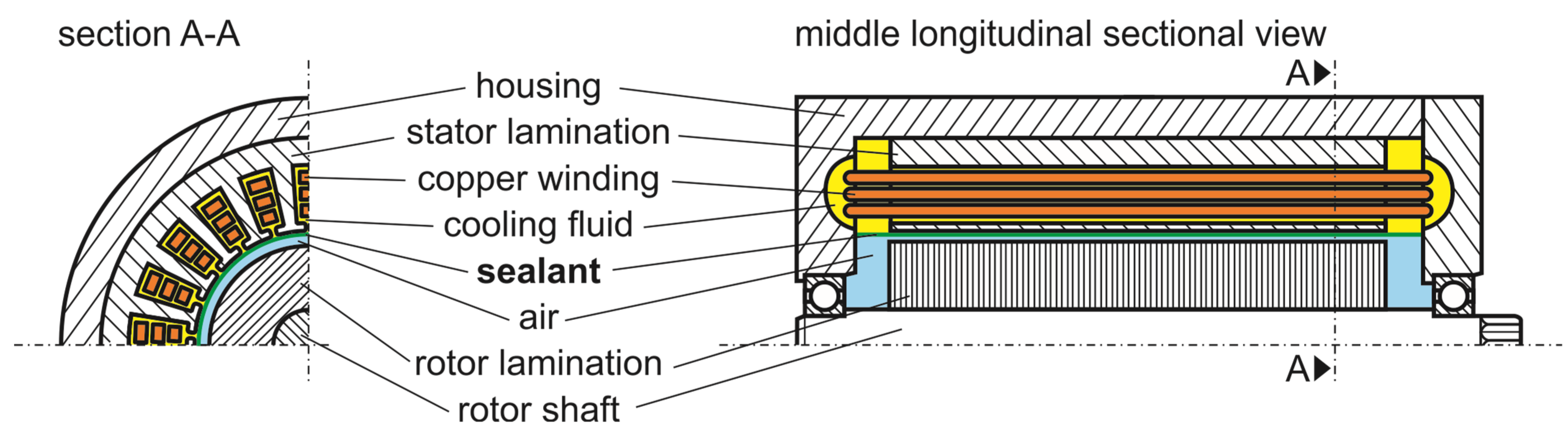
The outlined properties make them well-suited as a stator sealant in an electric motor, as shown in
Figure 1.
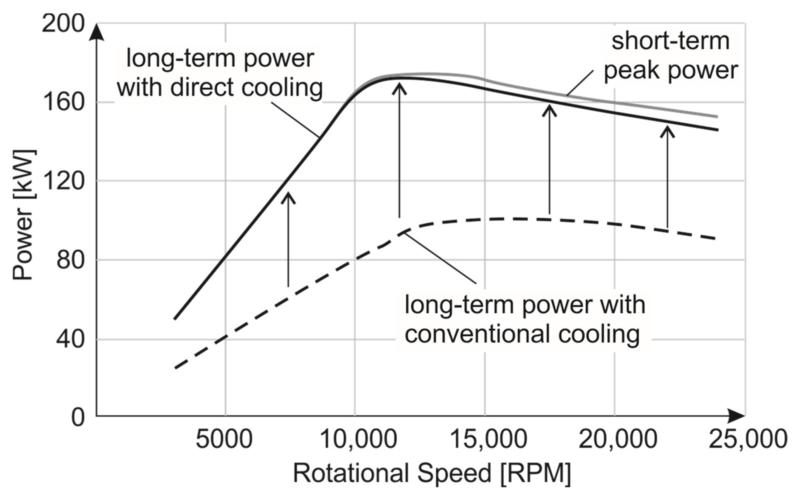
Sealing the stator provides the option of directly cooling the main heat source of the motor, i.e., the copper winding. Directly cooled electric motors are advantageous because their continuous power performance is close to their peak performance [
4,
5,
6] (see
Figure 2), and they reduce the overall losses of the motor. Because the cooling fluid is in direct contact with electric conductors, e.g., with the copper winding, it has to be dielectric as well. A cooling fluid fulfilling these requirements is, for example, polyalphaolefin (PAO) oil.
The influence of a glass fiber reinforced sealant on the performance of an electric motor is minimal under the following three premises according to [
7]: (1) the liner is not electrically conductive, (2) it fits into the existing airgap between the rotor and stator, and therefore, (3) its electromagnetic influence is similar to that of the airgap. The chosen material fulfills premises (1) and (3). Premise (2) requires the minimal possible wall thickness, which is determined by the mechanical loads. Regarding mechanical loads, the following two load cases have to be considered.
The first load case is the pressure of the cooling fluid applied to the outside of the sealant. To increase the sealants stability and stress resistance, it can be laminated onto the stator lamination for maximum pressure resistance [
8]. In this context, an extensive series of investigations of pressure-based blister tests are presented in [
9]. The herein presented results are taken as a given regarding thin-walled GFRP liners, which are glued to a metallic specimen using the laminates epoxy resin in a co-curing process.
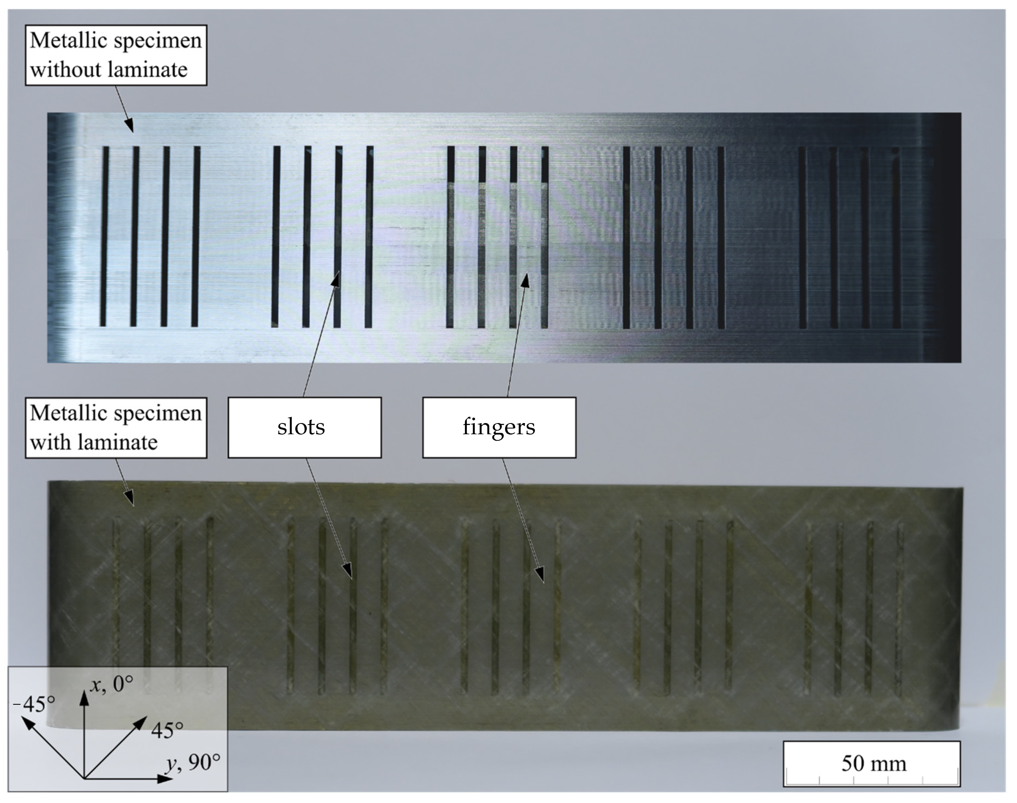
Figure 3 shows the used metallic specimen without a sealing laminate, as well as the metallic specimen sealed with a laminate. The specimens represent a stator lamination with its slots. The slots are pressured in the blister test with PAO oil at different temperatures. As a consequence, the GFRP layers have to withstand biaxial thermal strain states introduced by the specimen and a biaxial stress state created by the biaxial bending under internal pressure.
The second load case arises from the residual stresses due to the differences in the CTEs between the stator lamination and the sealant. In this research, we consider the second load case as a possible cause for the loss of the sealing function and examine it theoretically (see
Section 3). An advantage of anisotropic composite materials over isotropic materials is that a composite laminate can be designed according to specific structural requirements, such as a CTE corresponding to the substrate in order to minimize residual stress in the laminate.
1.2. Learnings from Pressure Vessels
A well-known application of fiber reinforced plastics under biaxial stress states and permeability issues are pressure vessels. Multiple concepts for pressure vessels are still the object of research [
10,
11]. To achieve good fiber utilization, IFF must be admitted. This requires additional components to guarantee impermeability for gas or fluid. The phenomenon is known as weeping [
12,
13].
The following section provides an overview of liners in pressure vessels, which face stress states comparable to the biaxial stress states occurring in the liner on a heat sink.
A common approach is to achieve impermeability, either with a metallic or thermoplastic liner [
14,
15], as well as chopped fibers [
13]. While the carbon fiber reinforced plastic (CFRP) structure suits structural purposes, the liner guarantees impermeability. But of course, the metallic liner reduces lightweight potential. In addition, a multilateral mixture leads to residual stresses due to differences in the CTEs. A potential variant is to produce pressure vessels without liner [
16,
17]. Impermeability is achieved through thick structural CFRPs, which, however, leads to poor fiber utilization.
Several authors have examined leakage in the context of propellant tanks since CFRP was first considered to be used for such tanks [
18,
19,
20,
21]. Kumazawa studied extensively the leakage of helium gas through CFRP with flat laminate specimens consisting of eight or more plies under mechanical loading at room temperature [
22,
23]. Kumazawa detected IFF cracking qualitatively with ultrasonic C-scanning in all plies. He distinguished IFF density due to the induced strain on the specimen. He showed that the leakage onset depended on the stacking sequence. Yokozeki evaluated gas leakage through composite liners with helium, also using flat specimens, and compared leakage at room temperature and under cryogenic conditions [
24]. He found that low temperatures themselves did not influence leakage, while mechanical loading during testing influenced the leakage significantly. Yokozeki discussed the dependence of the crack angle with a permeability model and found that a smaller crack intersection angle led to more leakage [
25]. Bechel examined leakage with helium gas after thermocycling and found a significant influence of the laminate stacking sequence [
19]. Mertiny presented a method for weeping investigations with fluid in tubular specimens with several layups and fiber angles at room temperature [
26], as well as elevated temperatures [
27]. Majid found different leakage rates for bismaleimide and epoxies at elevated temperatures [
28]. Flanagan described helium-based tests with thermoplastic matrices in the context of propellant tanks [
29]. Sebaey presented a study about leakage after low-velocity impact with different fiber angles and found good resistance with fiber angle mismatch [
30]. Multiple authors described analytical, as well as simulative, investigations in order to describe leakage [
31,
32,
33,
34,
35], as well as a micro RVE approach [
36]. A good overview of pressure vessels with weeping is presented by Prabhakar et al. [
37].
The literature overview shows a variety of investigations with extensive test setups with gas. Testing with gas has the significant advantage that it can be quantified comparably easily. The employed testing gas is usually helium due to its small molecular structure and inflammability. Most of the investigations examined multiple laminate designs with six or more plies. The following study examines leakage with PAO oil, which is colored (specified in
Section 2), on thin-walled laminates with only two plies. Testing with the cooling fluid, i.e., the PAO oil, is necessary to represent the given real application. Leakage with any given liquid, however, is more difficult to quantify. Therefore, the following study chooses visual inspection to assess leakage of the PAO oil, as suggested in [
27]. In addition, a dye penetrant is used to visualize cracks on the laminate specimens.
1.3. Main Contributions of the Investigation
The main contributions of our investigations are twofold. Firstly, two innovative test setups were developed (see
Section 2) and validated by the weeping investigations (see
Section 5). These test setups are simple and efficient, especially for qualifying the sealing function of stator sealants as well as localizing leakage and therefore weeping. Their essential principles, therefore, can be used to develop product-specific testing apparatuses, as was done, for example, in [
38].
Secondly, the weeping investigation of the laminates provides the requirements for a thin-walled, two-layered laminate composite seal for a stator lamination. It is shown that either at least one ply has to be flawless or, alternatively, an additional third sealing layer has to be added. These results have influenced subsequent developments in respect of flawlessness in production e.g., in [
39,
40].
Through both these contributions, this paper presents formerly unknown knowledge.
1.4. Premises for the Investigation
In general, for each application, its own leakage criteria needs to be defined. The required leakage tightness in this application is fulfilled if no visible leakage occurs within 5 min. This is referred to as technical tightness in the following. A preliminary study showed that, if leakage occurs, it does so within the first minute, for a two-layered laminate. Representative specimens without leakage are tested exemplarily over a period of 72 h, with no change in permeability.
Additionally, IFF was deliberately induced into the specimens, which were produced for this investigation (see
Section 4).
2. Developed Test Setups
Two test setups were developed to qualify the leakage through thin-walled GFRP stator seals. These setups are realized as compact test benches in order to perform the weeping test (see
Section 5). Before the test setups are described in detail, the testing media are briefly introduced as a preliminary insight.
2.1. Testing Media
In the two test benches, three test media were used. The main testing medium is the given cooling fluid, a PAO oil. All tests were performed at room temperature (23 °C), so the temperature-dependent viscosity of the oil was approximately 9 MPas. For better visual detection, the oil was colored with Unisol Liquid Red BHF by United Color.
To further enhance the visualization of cracks, a liquid dye penetrant was used, which was colored contrast penetrant Type 2.
As a third testing medium, surrounding air was used in the vacuum test setup. The boundary conditions were 144 m above sea level and 23 °C.
2.2. Test Setup for Pressure Tests
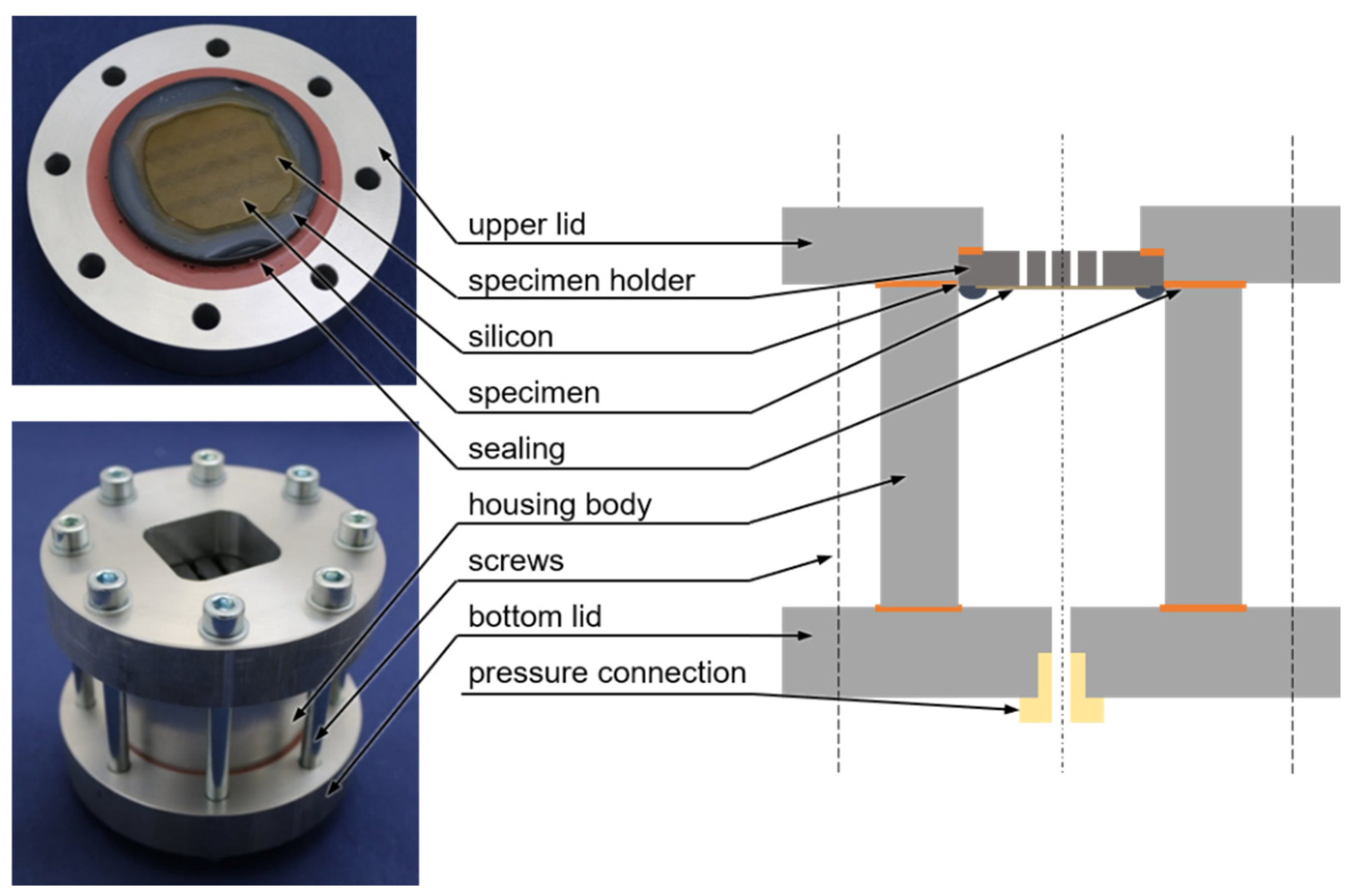
For performing permeability tests of test specimens, a test setup was developed for pressures up to 5 bar.
Figure 4 shows the setup in detail. It consisted of 2 lids around a housing body. The specimen was glued with a sealing silicon to the specimen holder. The specimen holder was 3D-printed in order to have the possibility to test different supporting structures. In this case, the specimen holder had a gap width of 2 mm with a gap spacing of 7 mm, based on [
8]. The test setup was pressured only with colored PAO oil as a test medium through the pressure connection on the bottom.
The test bench design allows for a quick change of specimen in the holder. The setup allows also the observation of the specimen while being tested.
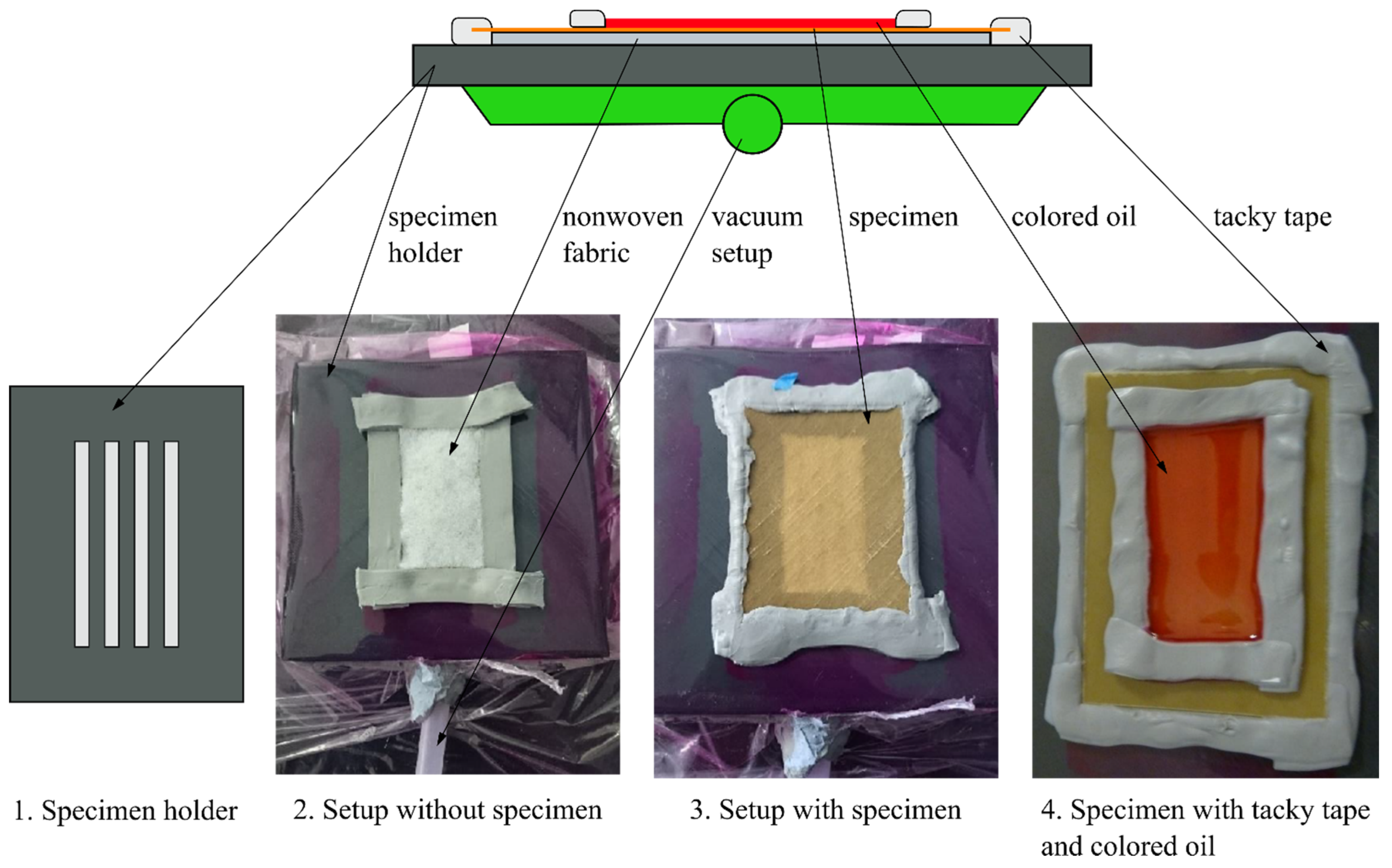
2.3. Test Setup for Vacuum Tests
In general, the advantage of a vacuum test setup is, theoretically, that it allows a first quantification of leakage, especially if different test media are used. Its disadvantage compared with the pressure test is obviously its limit of the pressure difference to test values below 1 bar.
Figure 5 shows an overview of the vacuum test bench setup. The basis is the specimen holder with the same gap pattern, as being used for the specimen holder in the pressure test bench. For enhanced visual leakage detection, a white nonwoven thermoplastic fabric can cover the specimen holder. Around the specimen, a thermoplastic vacuum film ensures that no leakage occurs, circumventing the specimen. Tacky tape seals the specimen and holds it in place. In order to reduce oil flow around the specimen, one additional tacky tape barrier seals the specimen. For leakage detection, the test media (colored PAO oil, dye penetrant, or air) are poured onto the specimen in the recess formed by the tacky tape. The test bench is operated with a Trivac D4A vacuum pump by Leybold Heraeus. The pump reaches a stable pressure plateau of 2 mbar in 2 min in this setup. The vacuum setup also enables the detection of air leakage by not using a fluid.
3. Analytical and Numerical Considerations for the Laminates
The following considerations are based on predevelopment material properties [
41] (properties of actually used laminates to be found in
Section 4.1). The GFRP laminate considerations employ Classical Laminate Theory [
42,
43]. The GFRP liner is subjected to pressure load stemming from the cooling fluid, as well as thermal loading. The thermal loads derive from the CTEs of the laminate and of the substrate.
Pressure loading leads to interlaminar shear and bending of the laminate, depending on the aspect ratio of the slot width. In order to keep IFF exertion at a minimum, the fiber direction of at least one ply needs to be placed with a small bridging width over the gap (90°). The second ply is mainly necessary to protect the first ply from handling and manufacturing influences. In addition, the second ply reduces creeping at high temperatures. For different aspect ratios between gap length and gap width, a second ply is suitable to cover the second bending direction.
Figure 3 (
Section 1.1) shows the fiber orientation of the laminate with respect to the main strain direction in the
x-direction. Quantitatively, a pressure of a maximum of 5 bar leads to neglectable exertion as long as not all layers are parallel to the slots (0°).
Another premise is a 90° angle between the two plies of the laminate under investigation. This angle was chosen for two reasons. Firstly, it is favorable for a perspective industrialized application, as commercially available prefabricated fiber layups come with fiber angles of 90°. Secondly, the induction of IFF into such composite specimens is distinct, as well as homogeneous (see
Section 4.2).
Setting aside the pressure from the cooling fluid, which was investigated in [
9], in the given setup, the temperature load dominates the laminate design. The temperature load arises from the difference between the operation temperature and the stress-free temperature of the laminate. The stress-free temperature depends on assumptions between
Tcure,
Tg,onset,
Tg,onset-20 K, and two-thirds of
Tg,onset [
44] after manufacturing. For the purpose of the analytical considerations, the stress-free temperature is assumed to be 160 °C. In general, time-dependent relaxation effects ease this exertion. Time-dependent relaxation effects are neglected in all considerations in this paper, which is a conservative assumption, thus representing the worst possible case.
The substrate, i.e., the stator lamination of the electric motor, has a CTE of 35 × 10
−6 K
−1 in the global
x-direction (i.e., the longitudinal direction parallel to the drive axis of the motor) and 13 × 10
−6 K
−1 in the
y-direction (i.e., radial around the longitudinal direction of the motor), thus effectively being an orthotropic structure. Assuming that the given supporting structure is by magnitudes stiffer than the liner, a premise is that the supporting structure dominates the overall structural behavior. This assumption is valid for compliant, thin-walled GFRP laminates on the rather thick stator lamination consisting mainly of a metal. Therefore, the supporting structure induces strains from the difference in thermal expansions into the GFRP laminate. In the following, the stresses in the GFRP laminate due to differing thermal expansions of the substrate and GFRP laminate are evaluated in each ply. Strains are transformed to the overall direction of the ply. Laminate stresses are evaluated using unidirectional material properties. IFF exertion is evaluated by employing the failure criteria according to Puck [
45].
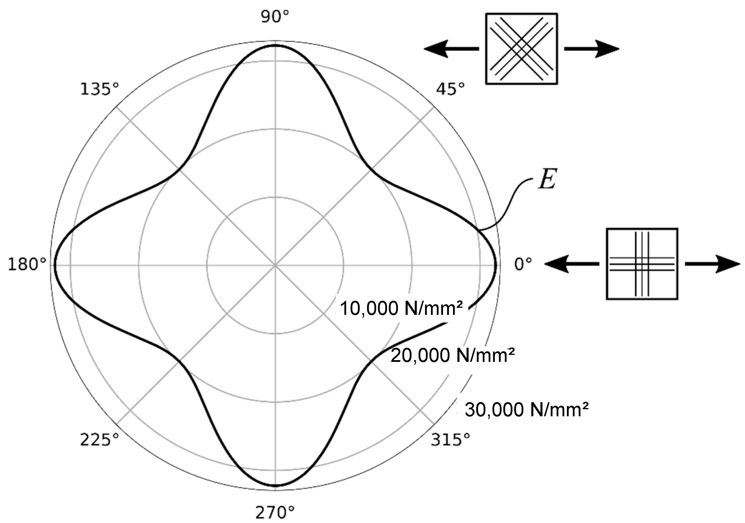
Since the stator lamination has a rather high CTE in the longitudinal direction, the main strain in the laminate will occur in this direction. Therefore, it is favorable to choose the ply orientations [+45°/−45°]. because the same strain will occur in both layers of the laminate.
This will guarantee that both plies have similar IFF exertions due to the strain induced by thermal strain.
Figure 6 shows the resulting stiffness in the form of the effective modulus of elasticity of the laminate dependent on the fiber orientation. The membrane stiffness reduces up to two-thirds compared with a [0°/90°] laminate.
With this, the CTE of the GFRP can be computed. The CTE of a ply is assumed to be 4.3 × 10
−6 K
−1 in the (1)-direction and 26 × 10
−6 K
−1 in the (2)-direction after [
34], wherein the (1)-direction is the fiber direction, and the (2)-direction is the in-plane direction perpendicular to the fibers. The (1)-direction of the outer ply equals +45° direction, while −45° equals the (2)-direction. An overview of the employed coordinate system orientation is given in
Figure 3 (
Section 1.1). The global CTE of the laminate becomes 13 × 10
−6 K
−1, both in the
x- and
y-directions of the application.
Figure 7 shows the IFF exertion in one ply of a [0°/90°] laminate subjected to the resulting strain difference between the substrate and the GFRP laminate with a temperature difference from the stress-free temperature of 160 °C to 20 °C. The IFF exertion becomes small when the fiber direction equals the small strain direction (0°/180°). The fiber failure exertion is at about 0.3. The IFF exertion does not become zero because of constraints imposed on the transverse expansion. It becomes 0.1 with strain normal to the fiber direction.
These analytical considerations show that [+45°/−45°] is a suitable layup for a laminate with a sealing function, as required in the current application.
4. Specimen Preparation for Weeping Investigations
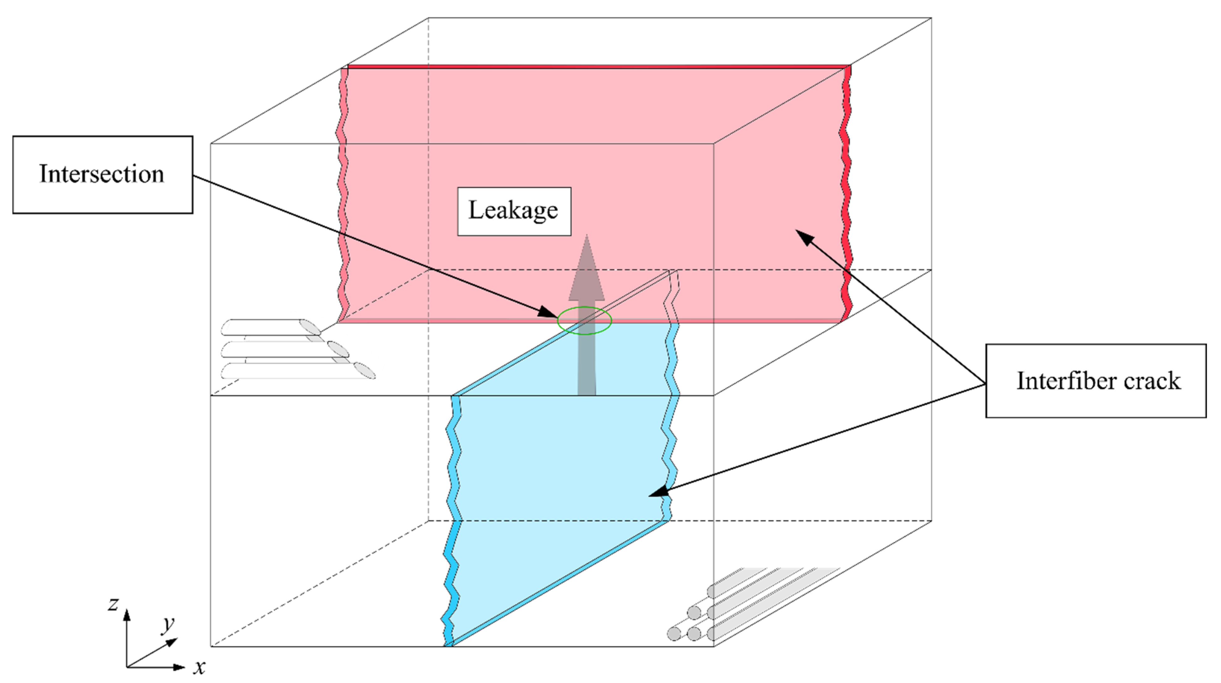
In order to conduct the weeping investigations of
Section 5, specimens with cracks due to IFF have to be provided. The working theory regarding weeping of a two-layered laminate is that weeping occurs if IFF cracks of both plies intersect according to the schematic sketch in
Figure 8.
The specimen size is 50 mm by 70 mm in accordance with DIN EN ISO 14125 [
46]. In the following subsections, the initial specimens, the induction of IFF cracks, and the specimen with a sealing layer are described.
4.1. Initial Specimens
As presented in
Section 3, specimens with two plies and fiber angle differences of 90° are considered for weeping investigations. The specimens have the layups [0°/90°] and [+45°/−45°], respectively. The specimens were manufactured using two different prepreg systems. The first prepreg system was the amin-based MTC400-1 with E-glass fiber PPG1062 by SHD Composite Materials (Sleaford, UK). The second system was a prepreg made of an inhouse-developed epoxy system. It is an anhydride-hardened epoxy with an E-glass fiber S2300 by Owens Corning (Toledo, OH, USA).
Figure 9 shows the elastic and strength properties of both systems, which were determined according to DIN standards with ten specimens each and are published in more detail in [
9].
The specimens were processed in an autoclave process as presented in [
47] (see page 70, materials being defined as systems S1 and S2) and [
48] (materials being defined as systems C and D). The SHD Composite Material was cured with a pressure of 6 bar plus vacuum at 130 °C for 1 h and post-cured at 180 °C for 2 h. The inhouse-developed prepreg was cured with a pressure of 6 bar plus vacuum at 130 °C for 2 h and post-cured at 180 °C for 2 h.
4.2. Inducing IFF
The specimens were pre-loaded mechanically to induce IFF damage. The intended configurations of IFF were: (a) no IFF, (b) IFF in one ply, (c.1) IFF in both plies with a few intersections of cracks, and (c.2) IFF in both plies with multiple intersections of cracks.
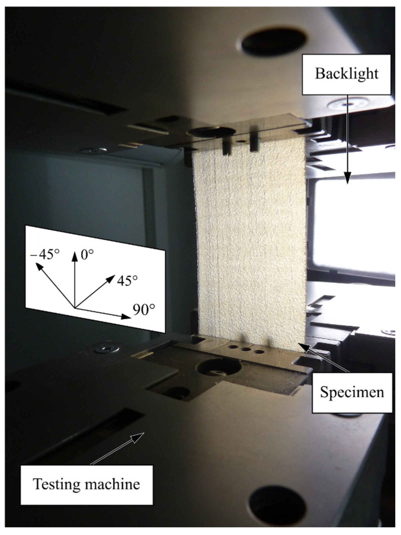
The specimens were prepared for performing the weeping tests by the application of mechanical loads to generate IFF cracks. Two methods for applying mechanical loads are presented. The first method is the application of a tensile load on a flat specimen with a standard testing machine Zwick 1475 (ZwickRoell, Ulm, Germany) (
Figure 10), which is operated in accordance with DIN EN ISO 527 [
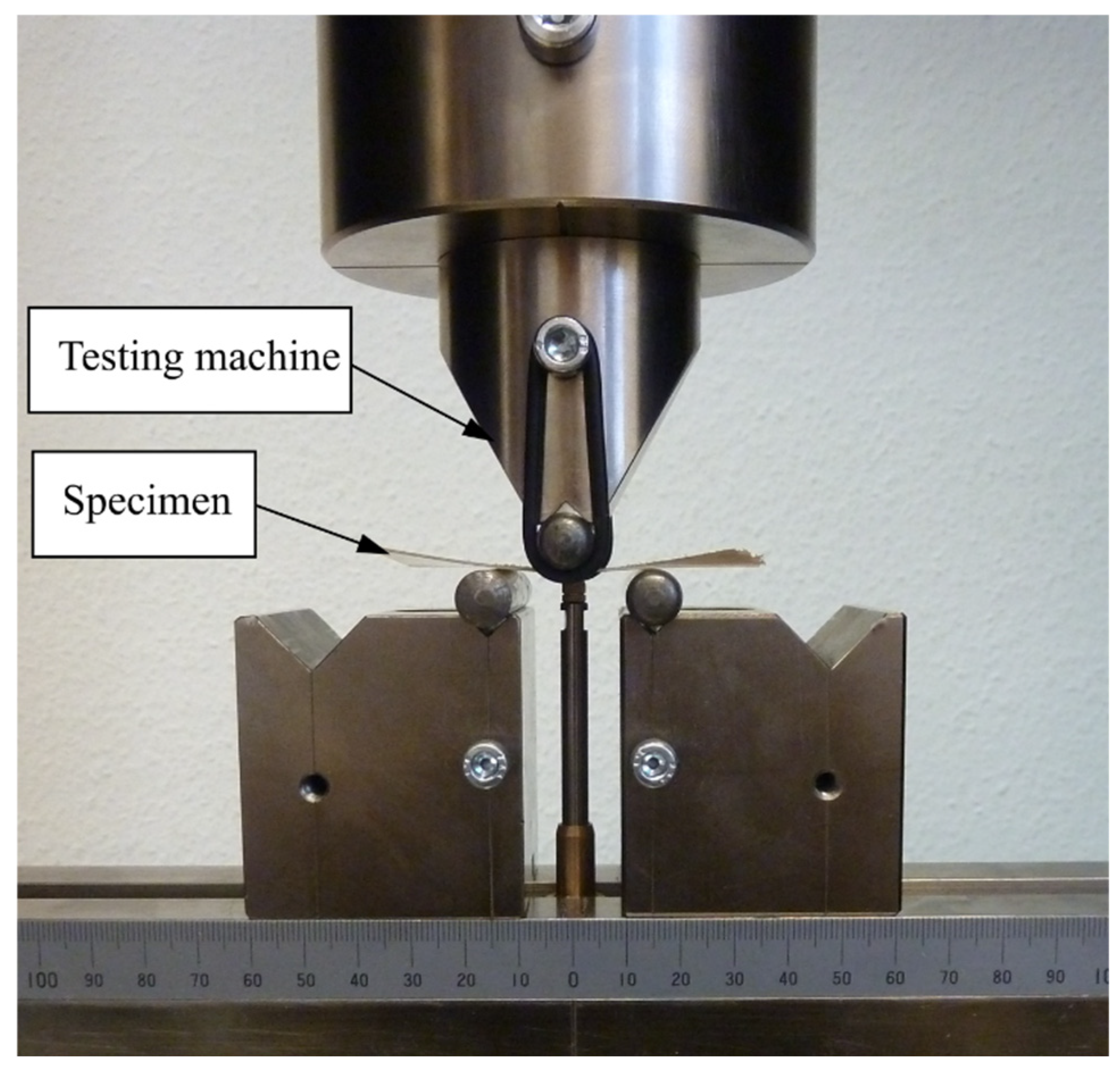
49]. The second method is a three-point-bending test on a flat specimen (
Figure 11) in accordance with DIN EN ISO 14125 (2011). In both cases, the load was applied with 1 mm/min.
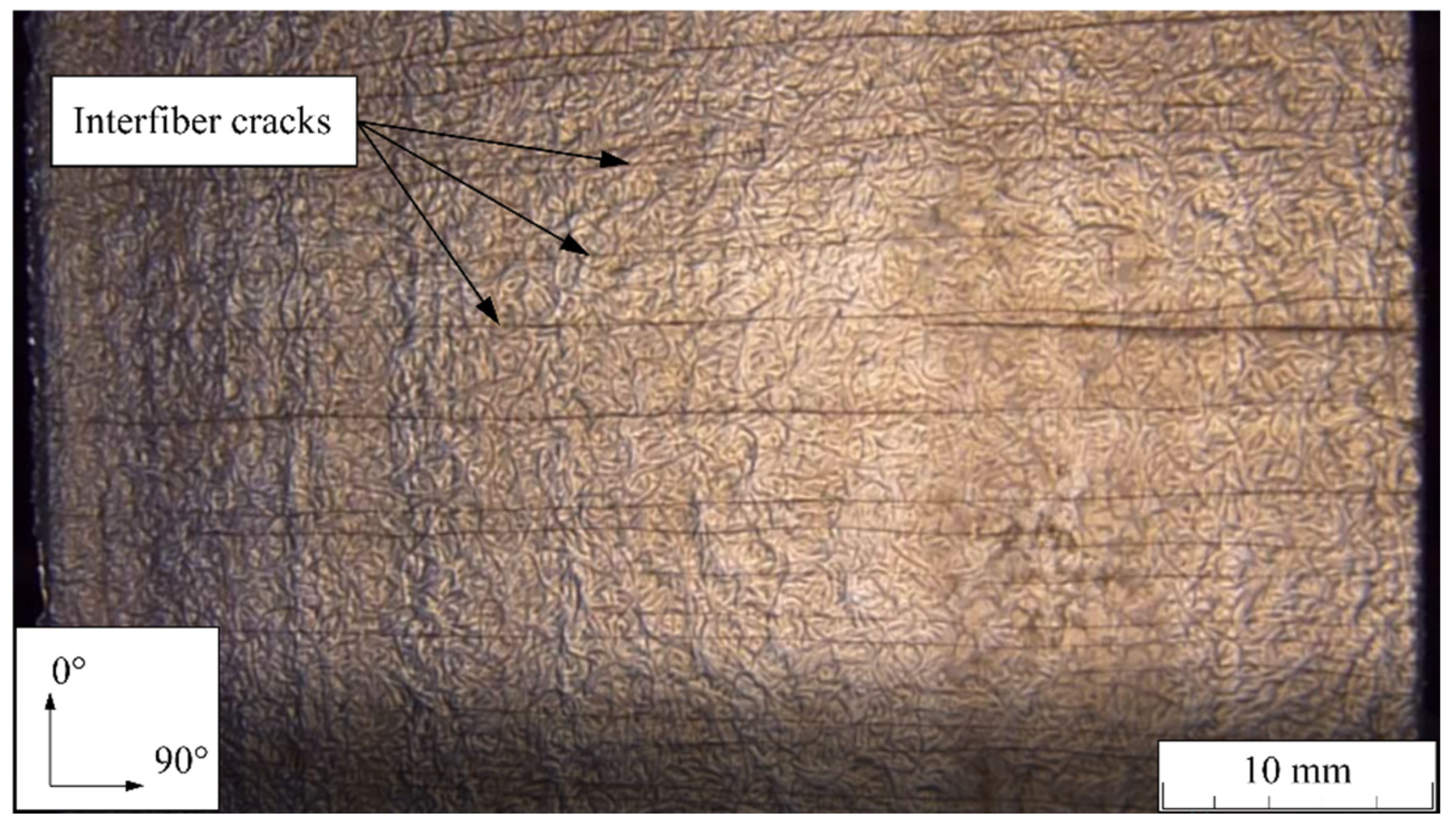
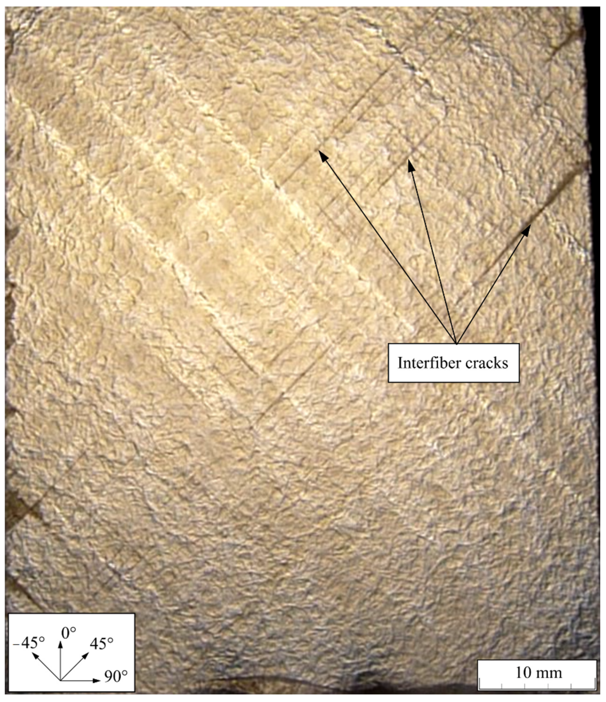
Inducing IFF by applying a tensile load worked well for [0°/90°]-specimens. It induced IFF in the 90°-layer homogeneously without damaging the 0° layer. The [+45°/−45°]-specimens, however, were damaged in both layers when this kind of load application was employed. IFF cracks spread all over the specimen, starting from the free edges with clamping. IFF accumulated at the edges and thus did not warrant an equal IFF crack distribution. Once IFF was initiated, the IFF cracks spread through the specimens in an unstable manner with little increase in the load.
Figure 12 and
Figure 13 show the results of loading the specimens under tension.
Figure 12 shows the homogeneous IFF crack distribution in the 90° layer in contrast with the rather inhomogeneous crack distribution in [+45°/−45°]-specimens, as given in
Figure 13.
The second method is inducing IFF by performing three-point bending tests. Three-point-bending works well on both layups. Therefore, bending was used for the [+45°/−45°]-specimens in order to induce IFF on a predefined area.
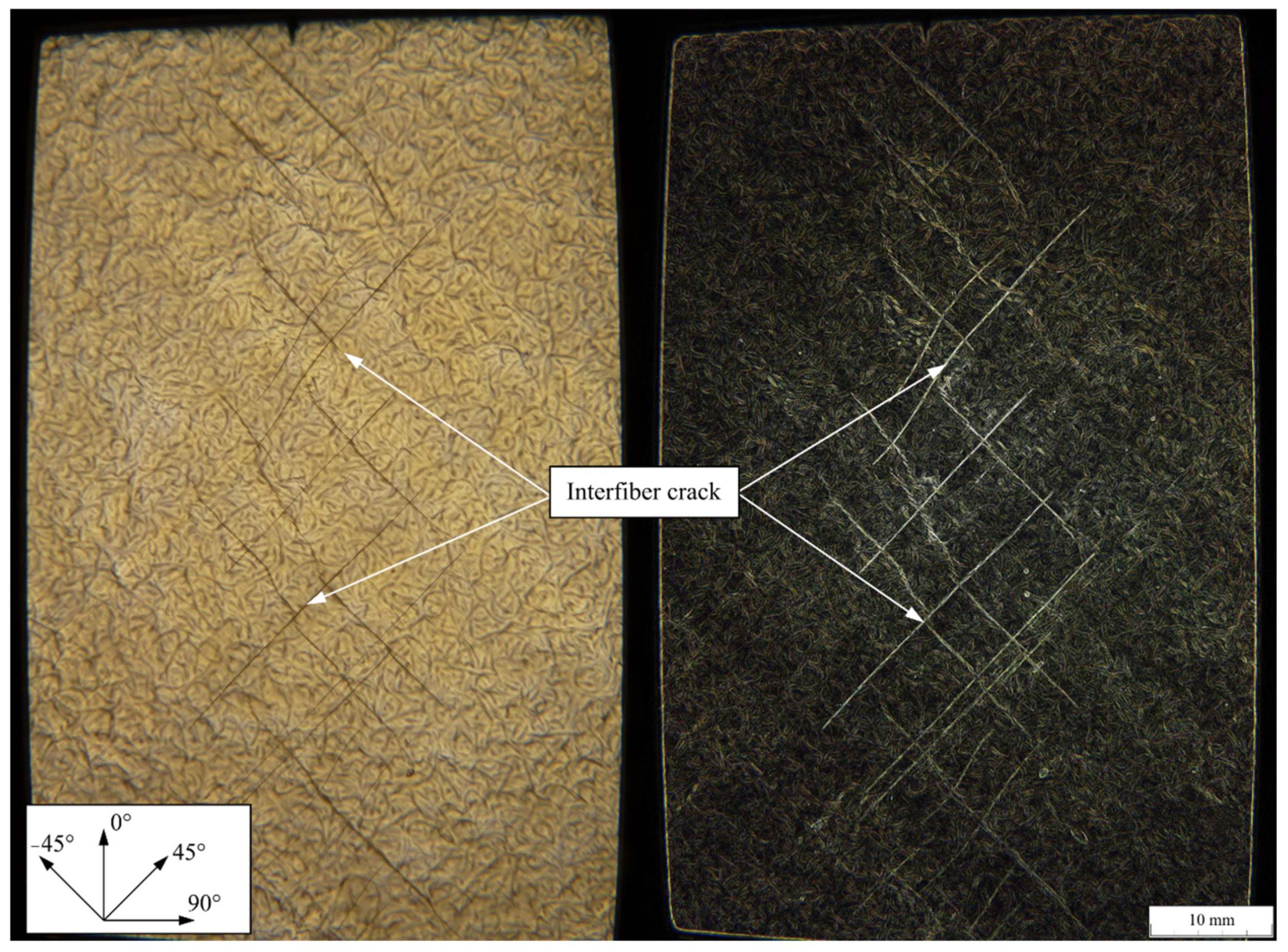
Figure 14 on the left shows cracks resulting from three-point-bending. Through applying bending load, the layer on the tensile side of the specimens showed IFF cracks. The layer on the compressive side remained undamaged due to the higher strength in compression of the employed fiber-reinforced plastics. In order to induce IFF in the other ply, the specimen was flipped and subjected to the 3-point bending again. To simplify the detection of IFF cracks, the contrast of each picture was enhanced with the Sobel algorithm as a built-in function of GIMP [
50] in
Figure 14 on the right. The Sobel algorithm has proven to be an adequate tool, especially for optical edge detection (see for example [
51]); it can therefore be used to process images of fibers, as shown for example in [
52,
53], or lightning damage to a composite [
54]. Since visible cracks come with edges, the Sobel algorithm yields good results in visualizing cracks due to IFF and was therefore used in this research.
This enabled the identification of IFF cracks in an automated manner and also the detection of crack lengths, as well as intersections of cracks. All of the tested specimens were visually checked in order to guarantee that they only exhibited the intended induced IFF cracks.
4.3. Specimen with Additional Sealing Layer
One supplementary laminate design was tested with an additional sealing layer. The additional layer consisted of a thermoplastic film. The layer was placed between the two laminate plies. The specimen was saturated with IFF in both plies according to specification (c.2).
5. Weeping Investigations
The two test setups were validated by the weeping investigations of the prepared specimens. The following two subsections are each dedicated to one of the two setups. The third subsection presents the findings for the specimen with the additional sealing layer, and the fourth subsection analyses the crack width.
5.1. Results of the Pressure Tests
The developed test setup and testbench achieved are described in
Section 2.2, and the specimens and their nominations a, b, c.1 c.2 are described in
Section 4.2. The tests were conducted with at least three specimens of each type for sufficient statistical validity.
The test procedure was as follows: the specimen was glued to the specimen holder and added to the upper lid, the setup was assembled and filled with the colored PAO oil, and the pressure was raised with a ramp of 1 bar per minute up to 5 bar. The setup was tested for technical tightness with a flawless reference specimen (a) without IFF. In this case, no technical leakage was visible after 15 min with a pressure of 5 bar.
For a specimen with no IFF (a) and IFF in one ply (b), no visible leakage occurred. No visible leakage occurred in (a) and (b). It was found that, as long as at least one ply had no IFF cracks, the specimen withstood at least 5 bar without visible leakage.
The results for the specimen with IFF in both plies showed leakage with no qualitative difference between specimens with a few intersections of cracks (c.1) or saturated with cracks in both plies (c.2). It therefore can be stated that, as soon as at least one intersection of cracks is present, oil leaks through the two plies, independent of the applied pressure. Visible leakage starts with pressure below 1 bar. From this finding, it can be deduced that it is valid to also use a vacuum test setup.
5.2. Results of the Vacuum Tests
Similar to the pressure test, the vacuum test (
Section 2.3) can be employed for a visual qualification of weeping. It also allows for an easy first quantification of leakage.
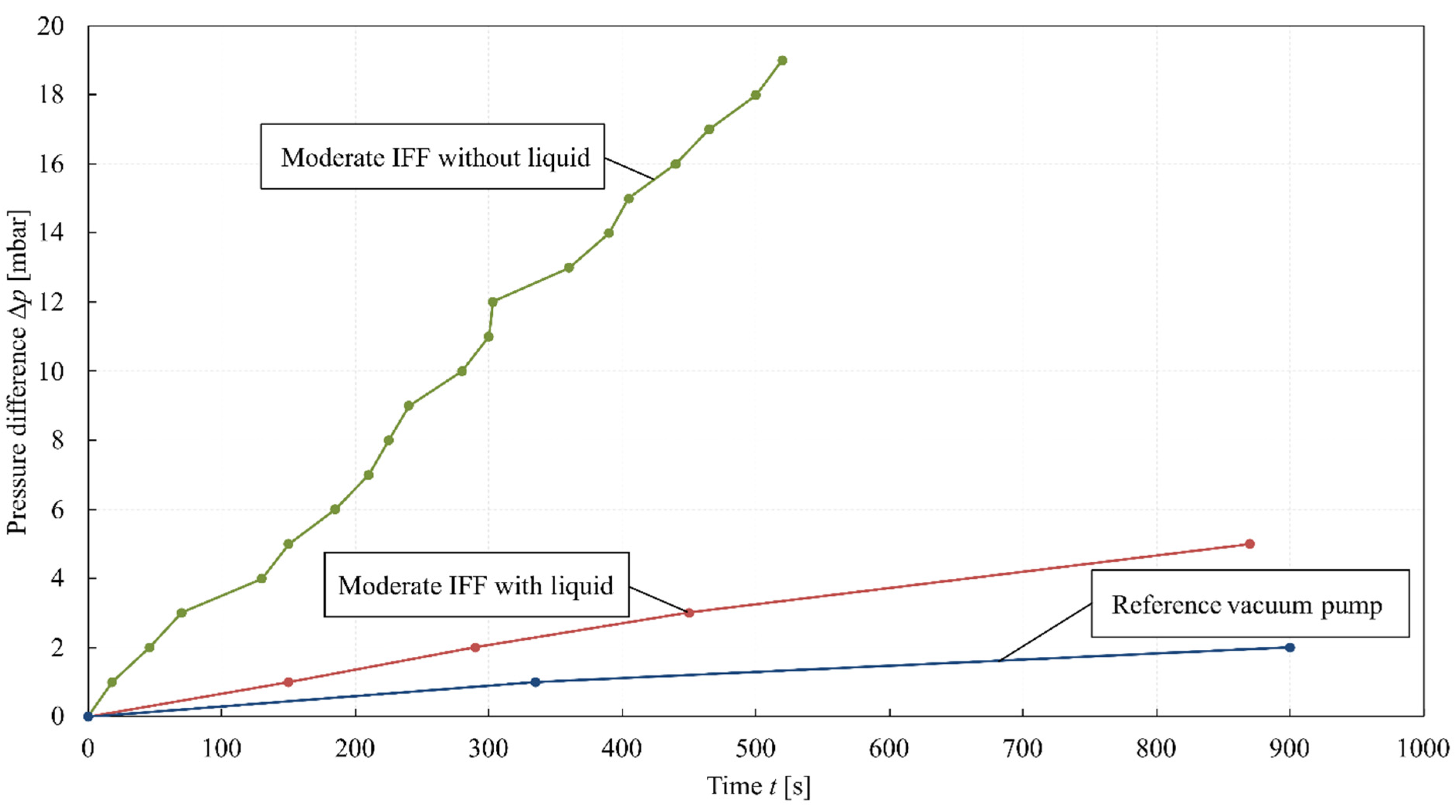
Figure 15 shows a representative pressure difference over time for several specimens after the pump is switched off. The dark-blue graph is the reference for the vacuum setup. In this reference, a thermoplastic film seals the setup instead of a specimen. The total increase in pressure in the reference vacuum test setup of about 2.5 mbar over 15 min is deemed to be sufficient for this investigation.
The green graph shows a specimen with moderate IFF density in both plies without a liquid on it. The red graph shows the same specimen in an additional test with a liquid on it. For the liquid, the increase in pressure between PAO oil and dye penetrant is negligible.
It can be observed that the increase in pressure over time was reduced by the liquid. This can be explained by the viscosity of the liquid being higher than the viscosity of air. Obviously, oil and dye penetrant have the same effect; both seal the network of cracks to an extent against airflow and therefore reduce the decrease in vacuum over time.
Different IFF densities of the specimen are not shown because they led to similar increases in pressure over time. Therefore, quantifying the density of IFF by quantifying the pressure difference over time is not possible.
For obvious reasons, the localization of cracks cannot be accomplished by using air as a testing medium. Accordingly, the two liquid test media, POA oil and dye penetrant, were used to detect the location of IFF cracks. The specimens of different IFF densities (a), (b), (c.1), and (c.2) showed qualitatively similar behavior regarding weeping, as can be seen in the pressure test up to 5 bar.
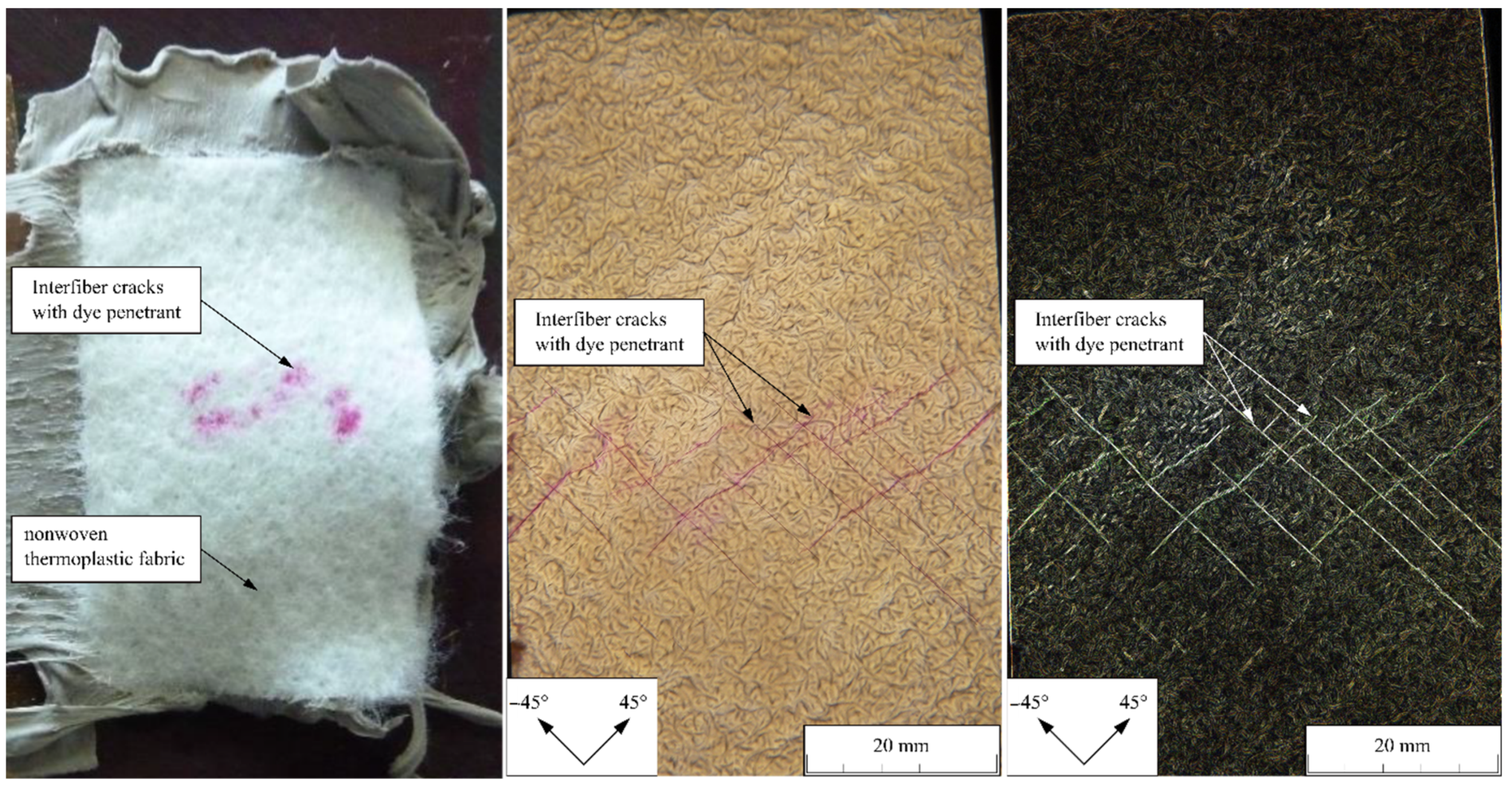
The results for both liquids were also qualitatively the same, but the dye penetrant offered a good visualization of cracks, especially when compared with pictures processed with the Sobel algorithm. This can be seen, for example, in
Figure 16.
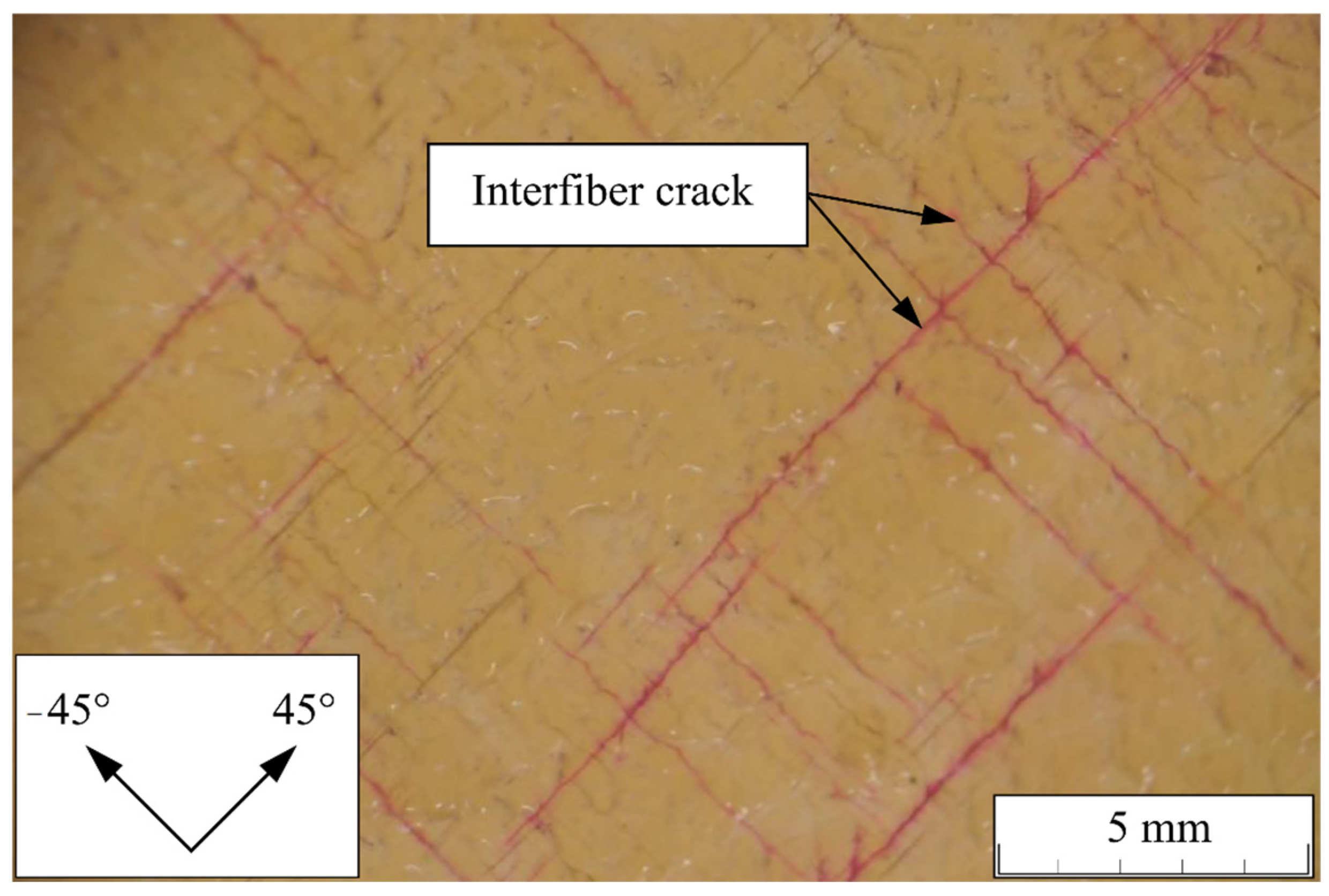
The dye penetrant additionally allows the identification of weeping through the specimens by a reflected-light microscope. In
Figure 17, dye penetrant can be seen in IFF cracks of both plies of a specimen in the same picture.
5.3. Vacuum Test of Specimens with an Additional Sealing Layer
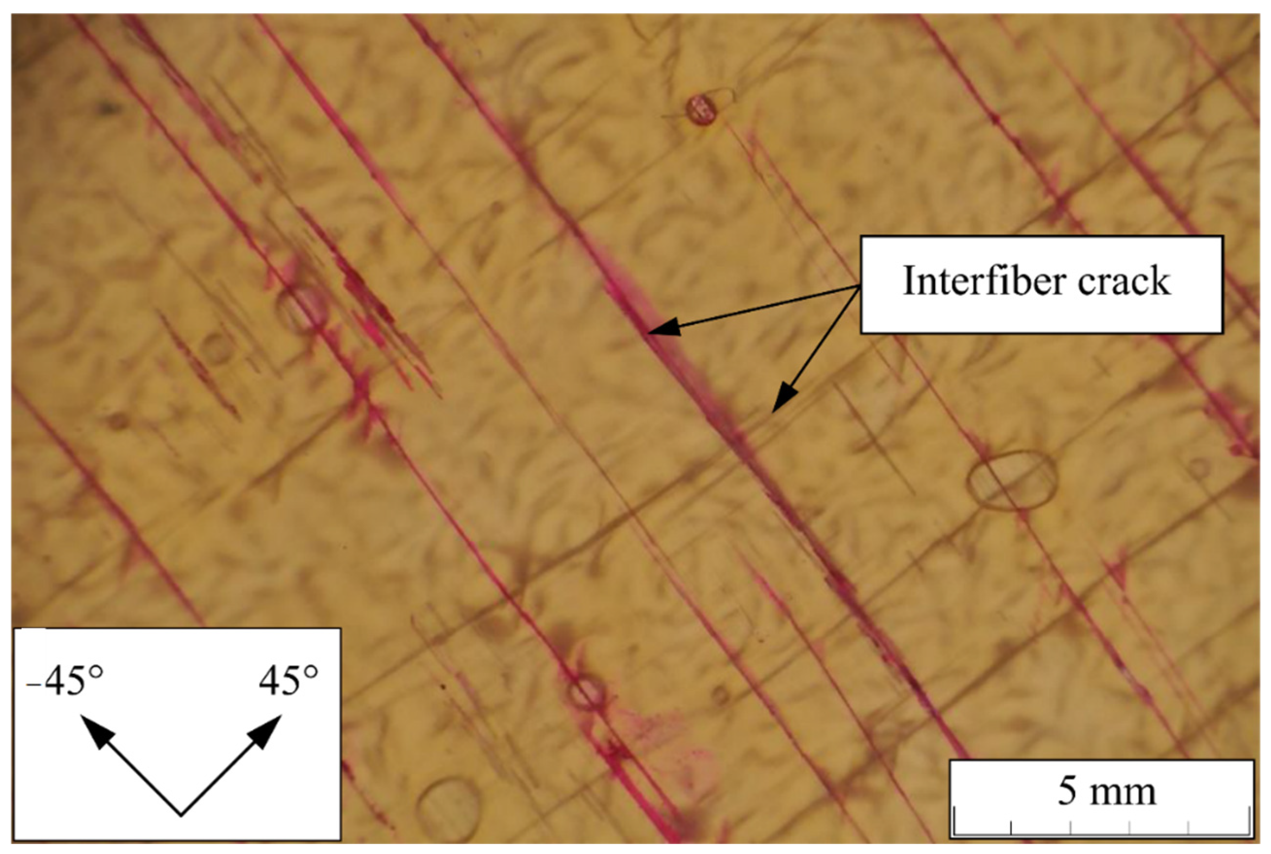
The specimens saturated with cracks in both plies (c.2) and a thermoplastic sealing layer between the two plies were tested with the vacuum test bench. In this case, no weeping could be detected.
Figure 18 shows a microscopic picture of such a specimen after testing with IFF cracks in both plies. In comparison with
Figure 17 the IFF cracks in the −45°-ply were filled with dye penetrant, while the IFF cracks in the +45°-ply contained none. This investigation shows that thermoplastic film between plies is valid to avoid leakage, if both plies have IFF cracks.
5.4. Determination of Crack Sizes
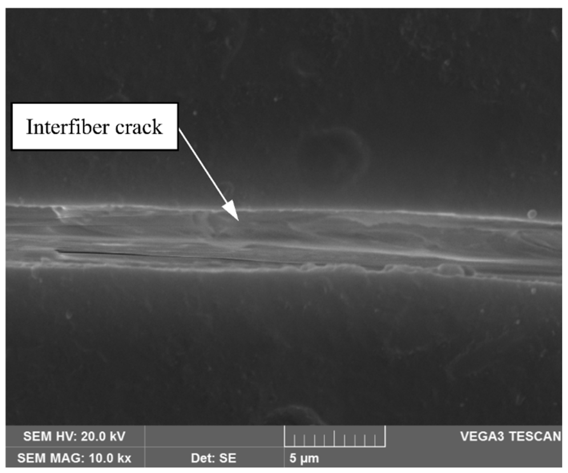
The investigations above show that small cracks already allow for significant gas flow through the resulting network of cracks.
Figure 19 shows a representative scanning electron microscope (SEM) image of a crack. The IFF crack size varied between 1.5 µm and 4 µm. IFF cracks remained unclosed, even if the specimens were not exposed to additional stress while the SEM image was taken. The width of the crack increased with additional stress.
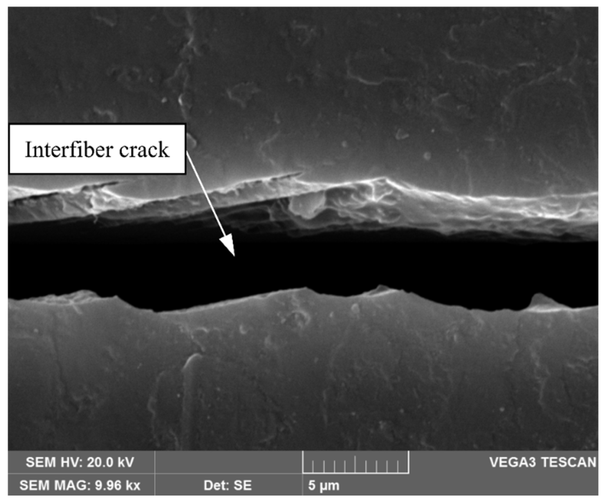
Figure 20 shows an SEM image with the specimen bent over a metallic tube segment with a curvature of 0.0139 mm
−1 (radius 72 mm). This resulted in crack sizes between 3 μm and 7 μm.
6. Summary and Conclusions
The two suggested test setups succeed in qualifying a two-layered laminate regarding weeping. The following conclusions can be drawn regarding the test setups:
The two developed test setups, a high-pressure test with cooling fluid and a vacuum test with air, cooling fluid, or dye penetrant, produce valid results regarding weeping;
The advantage of the pressure test bench is the possibility for testing with high pressures, if required. The advantage of the vacuum test setup is the enhanced visual control during the test. The vacuum test setup additionally is comparably simple to perform and requires less equipment;
The difference in viscosity of the two used fluids has been shown to play a less important role. Both the colored PAO oil and dye penetrant show similar weeping behavior;
The vacuum setup is not suitable to quantify the IFF density of a laminate.
The aim to design an efficient testing method has been met and has been considered for specialized testing apparatuses [
38]. Subsequently, the recommendations for further investigations are as follows:
For a more detailed quantitative evaluation, an additional test setup needs to be developed with the ability to generally quantify technical leakage of a laminate using a fluid test medium. Future investigations should also consider more specimens, ideally with automated evaluation of crack densities, and their influence on leakage of fluid through a two-layered laminate.
For the sealing of a stator lamination with a two-layered laminate as a sealant, the main findings from the presented investigations of this study are summarized as follows:
Undamaged two-layered laminates do not leak as well as laminates with IFF in only one ply;
Two-layered laminates leak as soon as IFF occurs in both plies and IFF crack intersection between the two plies occurs;
Laminates with intersecting cracks do not leak when a sealing layer is used e.g., a thermoplastic foil.
A [+45°/−45°] layup for the sealant provides the same strain due to thermomechanical-induced stresses in both plies of the laminate; it also is a suitable solution for the sealant;
A 90° angle between the two plies of the [+45°/−45°] laminate results in a CTE for the laminate approximately equivalent to the CTE in the radial direction of the stator lamination.
From these findings, the following conclusions and recommendations for future investigations can be drawn:
In order to seal a stator with a two-plie laminate, it is necessary to (A) choose a state of stress in which no IFF occurs, or (B) choose a state of stress in which IFFs only occur in one ply and do not intersect. If intersecting cracks occur, an additional sealing layer can stop weeping, as shown, although its type, position in the laminate, and influence on thermal and mechanical properties have to be quantified. If IFFs occur, the crack propagation due to alternating loads (e.g., cooling fluid pressure and thermal cycling) has to be further investigated. Such an investigation should be linked to the research regarding the mechanical behavior of the composite sealant, including the specific analytic failure model, which has been published in [
55]. Further investigations should also consider time-dependent effects on the laminates. So far, thermal cycling has been performed on the combination of stator and sealant, and can be found in [
47]. The degradation of both epoxy systems due to media exposure at elevated temperatures can be found in [
48].
In order to further reduce the residual stresses due to the difference in the CTEs of both the laminate and the stator, the fiber angle of the laminate can be adapted. The optimum angle is dependent on the CTEs of both the laminate and the stator, which both are, in themselves, anisotropic. For the combination of laminate and stator given in this paper, the angle between the two plies can be set larger, e.g., [+50/−50], thus lowering radial CTE and increasing the longitudinal CTE of the laminate. The required fiber angle can be computed in accordance with the methodology presented in
Section 3 above.


 ,
, 