Article

Analysis of the Deformation Mechanisms of Fabrics Based on rCF Staple Fiber Yarns for Thermoset Composite Applications

Institute of Textile Machinery and High Performance Material Technology, TUD Dresden University of Technology, 01062 Dresden, Germany
*
Author to whom correspondence should be addressed.
J. Compos. Sci. 2025, 9(4), 173; https://doi.org/10.3390/jcs9040173
Submission received: 2 March 2025 / Revised: 28 March 2025 / Accepted: 31 March 2025 / Published: 2 April 2025
(This article belongs to the Special Issue Feature Papers in Journal of Composites Science in 2025)

Abstract

:
The draping of textile semi-finished products for complex geometries is still prone to errors, e.g., wrinkles, gaps, and fiber undulations, leading to reduced mechanical properties of the composite. Reinforcing textiles made from carbon fiber (CF) rovings (i.e., endless continuous fibers) can be draped mainly based on their ability to deform under in-plane shearing. However, CF rovings are hardly stretchable in the fiber direction. These limited degrees of freedom make the production of complex shell-shaped geometries from standard CF-roving fabrics challenging. Contrary to continuous rovings, this paper investigates the processing of spun yarns made of recycled carbon fibers (rCFs), which are discontinuous staple fibers with defined lengths. rCFs are obtained from end-of-life composites or production waste, making them a sustainable alternative to virgin carbon fibers in the high-performance components of, e.g., automobiles, boats, or sporting goods. These staple fiber-spun yarns are considerably more stretchable, which is due to the ability of the individual fibers to slide against each other when deformed, resulting in improved formability of fabrics made from rCF yarns, enabling the draping of much more complex structures. This study aims to develop and characterize woven fabrics based on previous studies of rCF yarns for thermoset composites. In order to investigate staple fiber-spun yarns, a previous micro-scale modeling approach is extended. The formability of fabrics made from those rCF yarns is investigated through experimental forming tests and meso-scale simulations.

1. Introduction

Carbon fiber-reinforced polymers (CFRPs) offer many advantages compared to traditional construction materials such as metals, e.g., an outstanding strength-to-weight ratio, fatigue resistance, and design flexibility. Textile reinforcement structures provide an excellent balance between the simplicity of manufacturing preforms in the exact shape of the final 3D components and the ability to optimize material properties for specific applications. Unlike isotropic construction materials, textiles allow the alignment of fibers in the direction of applied loads, enhancing composite performance. However, the draping of textile semi-finished products for complex geometries is still prone to errors, e.g., wrinkles, gaps, and fiber undulations, leading to reduced mechanical properties of the composite and the need for oversizing the reinforcement structure [1,2]. The drapability of a textile semi-finished product refers to its capability to conform to a specific three-dimensional geometry under the influence of external forces. Achieving a requirement-oriented preform depends on two key factors: minimizing draping errors and ensuring the necessary load-adapted fiber orientations are attained.
Reinforcing textiles made from carbon fiber (CF) rovings (i.e., endless continuous fibers) can be draped mainly based on their ability to deform under in-plane shearing. However, CF rovings are hardly stretchable in the fiber direction (tensile strain below 2%). These limited degrees of freedom make the production of complex shell-shaped geometries from standard CF roving fabrics challenging. Depending on the textile structure and the preform geometry, undesirable distortions may occur. Contrary to continuous rovings, this paper investigates the processing of spun yarns made of recycled carbon fibers (rCFs), which are discontinuous staple fibers with a defined length or fiber length distribution.
The use of CF has been steadily increasing and is expected to further rise in the following years. In 2024, the average global demand for CF was estimated at 126,500 t, with aerospace, transport, sports, and wind energy being the main demand drivers [3]. While CF offers an exceptional strength-to-weight ratio and durability, its production and disposal have severe negative implications. The negative environmental impact of the production of virgin CF contradicts its positive influence on resource saving (e.g., fuel saving in cars or airplanes) due to lightweight construction, with the amount of energy needed for the production of CF being estimated to be in the range of 195–459 MJ/kg CF [4,5,6,7,8]. Additionally, the creation of CRFP waste due to decommission of composite structures is expected to rise in the future. In the European wind industry alone, a total of 350,000 tons of blade waste is expected by 2030 [9]. Although CFRPs have been declared non-hazardous in European waste directives, the landfilling of composites is prohibited in multiple European countries [10]. Therefore, methods to recycle carbon fibers for further use in new CFRPs are in demand.
Unlike rovings, staple fiber-spun yarns are considerably more stretchable, allowing the production of complex components with significantly fewer fabric blanks and cuts in the reinforcing textile. This capability comes from the deformability of staple fiber yarns, as individual fibers of finite length can slide against each other during deformation [11]. The improved formability of fabrics made from rCF yarns, resulting from yielding effects and the high extensibility of the yarns, enables the production of more complex-shaped CFRP components compared to conventional CF filament yarns. Preliminary tests by Goergen et al. [12] with tension rods demonstrated an elastic–plastic formability of the staple fiber composite material of up to 25%.
Previously, rCFs were used as short fiber reinforcements in thermoplastic compounds for injection molding [13,14], non-woven fabrics [15,16], and tape structures [17,18]. Such applications led to relatively poor mechanical properties. Spinning rCFs together with thermoplastic fibers into hybrid yarns has proven to have strong potential for achieving high fiber orientation and compactness, resulting in high fiber-volume content Vf. Such hybrid yarns were developed by means of roving frames [16], wrap spinning [12,19,20,21], and friction-spinning technologies [22]. Goergen et al. [11,12,23] manufactured organo sheets from rCF/PA6 staple fiber yarns (wrap yarns) and achieved a tensile strength of 800 MPa (Vf = 45%) [11,23]. In tempered tensile tests of wound UD specimens, a high deformability of up to 50% was found [23]. This elastic–plastic deformation is made possible by the inter-fiber sliding of staple fibers in the matrix.
Most investigations on rCFs relate to thermoplastic composites. Although their share has increased in recent years, thermoplastic-based composites only account for 28.8% of the total CFRP market [24]. The rest of the market is occupied by thermoset-based composites, which are characterized by better mechanical properties, higher thermal resistance, and lower costs in comparison to thermoplastics [25]. Therefore, in order for rCFs to be widely available on the market, a process chain for the production of thermoset-based CFRPs is required. Although the demand for thermoset-based rCF composites is high, the range of investigation on this topic is sparse. Yu et al. noted a tensile strength of 1509 MPa (Vf = 55%) from an rCF–epoxy composite based on the HiPerDiF (high-performance discontinuous fiber) method [26], while Rimmel et al. reached 600 MPa (Vf = 50%) using tapes [18].
In our previous studies [22,27], the fabrication of yarn structures comprising rCFs and low-melting co-polyamide fibers, with rCFs constituting over 90% by weight, was investigated using a DREF-3000 friction-spinning machine. Such yarns can be applied in thermoset composites. The yarn structure features a core composed entirely of rCF and a sheath formed from low-melting co-polyamide fibers, with a core-to-sheath weight ratio of 93:7. Both the carded and drawn slivers utilized in the process are exclusively composed of rCFs. The influence of spinning parameters on the tensile properties of yarns and the effects of spinning parameters on the tensile properties of unidirectional thermoset composites were analyzed [27]. A tensile strength of 1181 ± 71 MPa was found for UD thermoset composites with Vf = 41.3% [27].
Recently, different publications have described micro-scale models of spun yarn, e.g., [28,29,30]. However, those investigations dealt with cotton or polyester materials. In our prior studies [31,32], micro-scale models of ring-spun hybrid yarns (rCF/ PA6) and friction-spun rCF yarns were developed, respectively. The unit cell geometry of the yarn was modeled as a stochastic fiber network and the variability in the fiber geometry (e.g., length) was included in form of statistical distributions [31]. For the friction-spun yarns with high rCF-content, a three-dimensional finite element model consisting of core and sheath fibers was developed [32].
In the field of textile simulation, both continuum mechanical models (macro-scale models) and discrete models (micro- and meso-scale models) have been developed [33,34]. Macroscopic approaches treat textiles as continua with homogenized properties, where equivalent stiffness parameters are introduced to enable the formulation of shell elements [35,36,37,38,39,40,41,42]. This approach aims to accurately capture the flexible behavior of textiles. Conversely, discrete models have been developed to represent the textile structure at the yarn or filament level, allowing for the inclusion of detailed structural characteristics within the simulations [40,41,43,44,45].
Despite the advancements in staple fiber-spun yarn production, a systematic investigation into the utilization of their advanced deformability for the production of preforms for 3D composite components has not yet been carried out. The relationship between yarn properties and the structural characteristics of draped preforms and resulting components remains largely unexplored. Consequently, a comprehensive understanding of drapability is essential to fully use the potential of staple fiber composites with advanced material properties. This study aims to develop and characterize woven fabrics based on previous studies of rCF yarns for thermoset composites. In order to investigate staple fiber-spun yarns that are considerably more stretchable than rovings with continuous fibers, a previous micro-scale modeling approach is extended. The formability of fabrics made from those rCF yarns is investigated through experimental forming tests and a meso-scale model.

2. Materials and Methods

2.1. Materials

Staple rCFs with a fiber length of 60 mm were derived from cutting residual yarn spools (Tenax®-E IMS65 E23 24K, Teijin Carbon Europe GmbH, Wuppertal, Germany). To form a core–sheath yarn structure, low-melting co-polyamide staple fibers KA 115 (melting temperature: 123 °C) from EMS-Griltech (Domat/Ems, Switzerland) served as the sheath. The tensile properties of the fiber materials are summarized in Table 1 [27].
A card sliver was first produced on a modified carding machine with 100% rCF. The sliver was then drawn on the draw frame using a modified leveling unit. The drawn sliver was used for the core of the yarns, which were produced as core–sheath structures on a DREF-3000 friction-spinning machine (Fehrer AG, Linz, Austria). The yarn-spinning parameters were selected based on parameter studies carried out in [22] and were as follows: suction air pressure, −30 mbar; yarn delivery speed, 50 m/min; opening roller, 4500 r/min; and spinning drum, 2000 r/min. Yarns with a core–sheath weight ratio of 93:07 were produced with 800 and 1600 tex. Details of the production of yarn structure are reported in [27]. The structural and mechanical properties of the yarns as well as the filament-based references (from [46]) are given in Table 2 and Figure 1 (30 samples per type of yarn). The yarn properties have a stochastic character. Because of the core–sheath geometry consisting of staple fibers, frictional contacts between the core fibers occurring during sliding are the driving factor of the tensile forces in the yarn. Friction spinning with a high core–sheath ratio results in uneven coverage of the core by the sheath fibers, which leads to varying compaction of the core fibers along the yarn axis during axial deformation and thereby varying friction forces. Combined with the variation in staple fiber length, the occurrence of thin sections with high deformation, analogous to the Weibull theory of weakest links, is promoted.
Friction-spun yarns were further processed to woven fabrics with a width of 50 cm on a rapier-weaving loom of Lindauer DORNIER GmbH (Lindau, Germany). Then, 2/2 twill-weave patterns were produced with warp and weft densities of 3.9/cm and 4.0/cm (Figure 2). Figure 3 presents the top views of 800 and 1600 tex finished fabrics, respectively. The cross-sectional images show that the yarns have a circular cross-section in the fabric due to their high compactness. In addition, a 2/2 twill fabric (3.7 threads/cm) made from 800 tex CF rovings was selected to compare the properties of the rCF fabric with those of conventional fabrics.

2.2. Experimental Characterization of Woven Fabrics

The fabrics were characterized by tension, cantilever bending, and in-plane shear (Figure 4). Tensile tests were carried out following standard DIN EN ISO 13934-1, i.e., fabrics of a size of 50 mm × 200 mm were tested in weft and warp direction on a Zwick Z2.5 testing machine (ZwickRoell GmbH & Co. KG, Ulm, Germany). The bending properties of the fabrics were characterized on a bending testing device ACPM 200 (Cetex Institut GmbH, Chemnitz, Germany) according to DIN 53362 (cantilever bending). The machine automatically pushes the fabric over an edge, which then bends due to its own weight. When the front edge of the sample reaches a line running at 41.5° to the edge, the overhang length is determined, and bending stiffness can be calculated thereof. The shear properties were determined using a picture frame initially developed by Orawattanasrikul [47]. The fabric is loosely fixed to the picture frame with needles, which is then clamped in a uniaxial tensile testing machine and sheared into a rhombus. The textile shears in a constrained manner analog to the frame geometry. The force F applied in the shear tensile test and the traverse path d are recorded. The shear angle θ can then be calculated with the known leg length of the picture frame L = 200 mm. From the shear curves, the shear locking angle was determined following [48]. The friction properties of the fabrics on a metal surface were also determined according to DIN EN ISO 8295. All experiments were carried out under standard conditions according to DIN EN ISO 139.
The drapability of the textiles was analyzed on the boomerang testing setup [49]. The boomerang geometry features a free-form surface based on a segment of an automobile’s lamp top. Several individually controllable blank holder segments ensured adapted material guidance (Figure 5) and were systematically varied during the tests. The tests were carried out on a single 500 × 500 mm2 sheet of fabric.
After the drape test, the shape of the deformed textile was fixed using polyvinyl acetate for further handling. The textiles were optically evaluated for defects, and their yarn paths were determined for further validation.

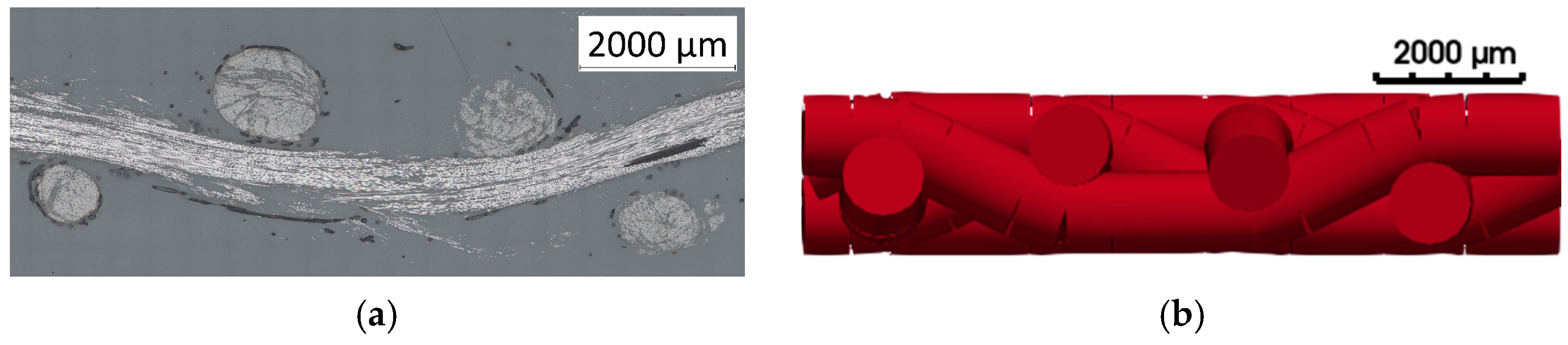
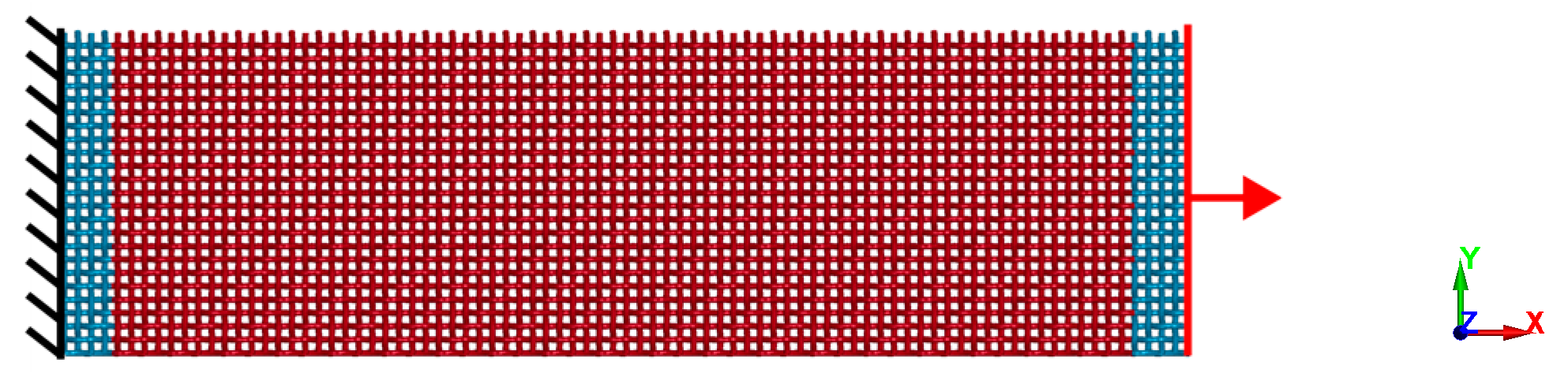
2.3. Meso-Scale Modeling of Textiles Made from Recycled Staple Fiber Yarns

For the prediction of textile deformation during the draping process, a meso-scale model was developed. An initial fabric geometry was achieved with the help of micrographs (Figure 6a). Since the yarns had a circular cross-section in the fabric, beam elements were used to model the yarn paths. The final realistic woven fabric geometry was reached by applying an additional compaction step. During the compaction step, virtual strains were applied to the yarns, resulting in shrinkage and reorientation and thereby generating realistic model geometry. Periodic boundary conditions applied on the nodes on the model boundaries ensured continuous yarn paths for periodic transformations.
As the yarns show a capability of high plastic deformation (Figure 11) because of fiber–fiber sliding mechanisms in their core, an elastic–plastic material model was used to replicate the yarns’ mechanical behavior in the axial direction. To model the pre-peak behavior of the yarns, a tri-linear elastoplastic material model was applied. Because of the high core-to-sheath ratio, the yield stress was assumed to be low in comparison to the maximum stress.
To model the post-peak behavior, the GISSMO damage model was applied [50]. The GISSMO model introduces a damage variable D for proportional loading (Equation (1))
D = ε p ε f n
with the accumulated plastic strain ε p , the fracture strain ε f and the damage exponent n . The apparent stress σ is further computed from the undamaged stress tensor σ using the damage variable and an additional fading exponent m (see Equation (2)).
σ = 1 D D c r i t   1 D c r i t m σ
To decouple the yarn’s bending stiffness and its tensile stiffness, a custom cross-section-integration rule was used and calibrated to experimental results.
Due to the stochastic character of the yarns, they exhibit a non-negligible variation in their mechanical properties (Figure 1). Thus, material properties were varied in the model based on the experimental data. An exponential Weibull distribution (Equation (3)) was selected to fit the maximum forces in the material model to the experimental data.
F x , a , k , λ = 1 e ( x / λ ) k a
Thus, the parameters a , k are the shape parameters of the distribution function, while λ represents the scale of the Weibull function. An additional location parameter l o c is included to offset the distribution. In the context of maximum force, the l o c parameter sets the lower limit of the variates generated by the distribution. The selected parameters for the Weibull distribution are provided in Table 3 with the resulting cumulative distribution function and the experiments depicted in Figure 7.
The Young’s modulus was kept constant (E = 1600 MPa) and linear damage behavior was implemented with a fading and damage exponent set to −11.5 MPa. The fracture strain was determined by introducing a constant post-peak modulus E d e s c , which was set to −11.5. In comparison to yarn tensile tests, the tensile behavior results could be sufficiently validated as is shown in Figure 8.
The previously described stochastic material model was applied to create models with randomized material properties in LS-DYNA. The models were further used in virtual tensile tests and draping simulations. For the tensile test simulations, a meso-scale model with the same dimension as in the experiments was generated. In the models, each element chain was assigned varying maximum stress. To prevent premature failure in the simulation due to the boundary effect, the dummy elements near the boundary were implemented using a linear elastic material model without damage and failure conditions. For the yarn-to-yarn interactions, a beam-to-beam contact model was established. A boundary condition was applied to the model following the experiments by fixing the nodes at the lower boundary in the x direction and applying a displacement on the upper x boundary (Figure 9). The force–strain curves were used for further validation.
For the draping simulations, a model setup was devised containing the same components (i.e., a stamp, blank holder, and die) for the experiments (Figure 10). Similarly to the tensile tests, a textile model with the same dimensions as in the experiments (500 × 500 mm2) was included. For the stamp, blank holders, and die, shell elements with rigid material models were introduced. During the simulation, first, a predefined load in the z direction was applied on the blank holders while fixing the holders’ displacement in the x and y direction. Afterward, a continuous displacement of the stamp in the z direction up until the end stop at the die was applied. The die was fixed in all directions.
From the simulations, the results were examined for damage in the beam element. Beam element orientations were extracted for further comparison to experimental results.

3. Results

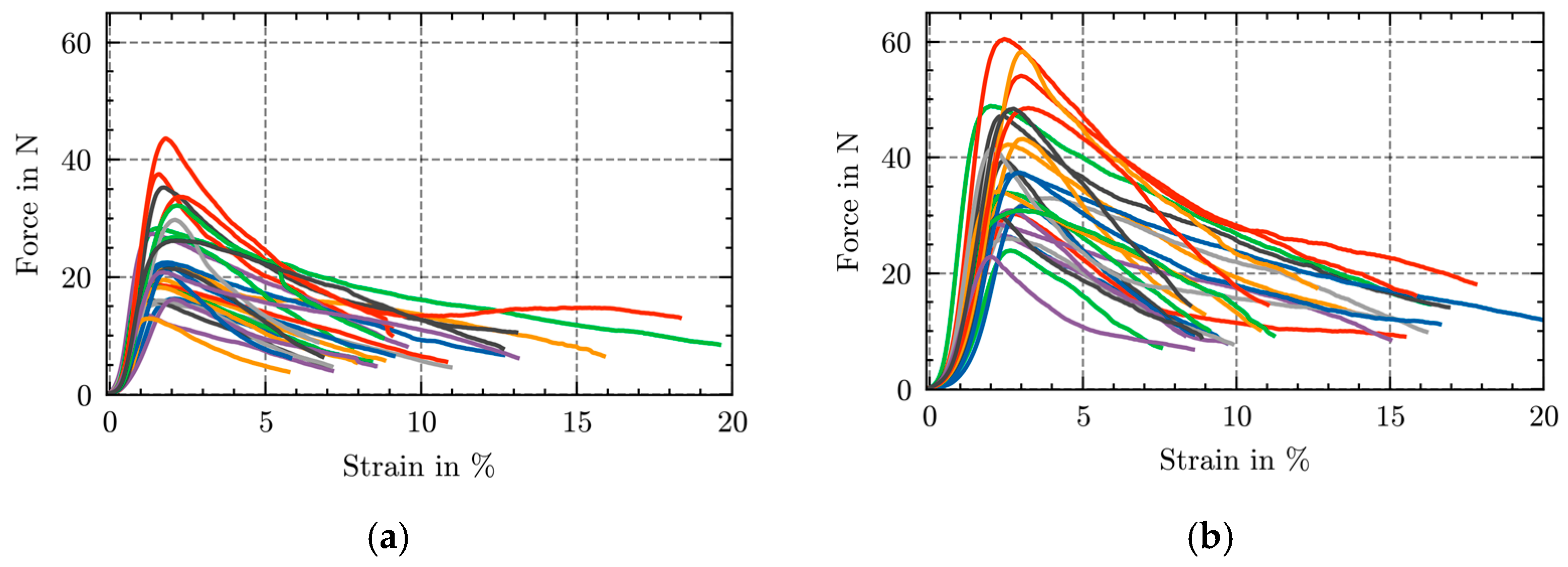
3.1. Fabric Characteristics

Following the previously described approach, tensile tests of the woven textile in warp and weft directions were carried out. The maximum force in the warp direction was 528.4 ± 120.9 N at an elongation of 3.40 ± 0.43%, while that in the weft direction was 558.2 ± 95.3 N at 8.71 ± 1.55%. Elongation at break in the warp direction was 22.63 ± 4.17%, and in the weft direction, it was 27.02 ± 2.25. An overview of the tensile properties in both directions is provided in Table 4, with respective curves in Figure 11. The results show a difference in tensile properties between the warp and weft directions. While the warp specimens reached their load maximum at lower strains compared to the weft specimens, the maximum value was lower than in the weft direction. The results indicate differences in yarn undulation. During weaving, a difference in warp and weft tension leads to variations in the densities in the warp/weft direction. Resulting from these differences, the yarns undergo larger structural deformation, orienting them along the loading direction before an axial deformation of the yarns occurs.
The textile shear properties were determined using the previously described approach. Figure 12 shows the measured shear curves. The maximum shear forces of the tested textiles were 15.08 ± 5.53 N and the shear locking angle was determined to be 34.38 ± 0.41°. Although the fabrics exhibited a large variation in maximum forces during shearing, shear locking occurred at the same angle. In comparison with filament-based woven fabrics, the rCFs’ shear forces were larger at lower angles. This is due to the surface structure of the friction-spun yarns, which enforces higher yarn-to-yarn friction in comparison with the even filament rovings.
The cantilever bending properties of the woven fabrics were determined as follows (Table 5). In the warp direction, the mean overhang length was measured to be 157.6 ± 11.3 mm, and in the weft direction, it was 137.2 ± 4.5 mm. On this basis, the bending stiffness was determined to be 291.4 ± 53.4 mNcm in the warp direction and 188.4 ± 19.3 mNcm in the weft direction. Here, the difference in yarn orientation resulted in a difference in bending stiffness.
The frictional properties between the textile and a steel surface were determined as follows (Table 6). In the warp direction, the static friction coefficient of rCF-DREF yarns was measured to be 0.312 ± 0.015 and the dynamic friction coefficient was found to be 0.306 ± 0.010. In the weft direction, the static coefficient was determined to be 0.305 ± 0.008 and the dynamic coefficient was 0.307 ± 0.010. Figure 13 shows the load–displacement curves during friction testing. In comparison to CF yarns, the frictional coefficients were larger. The reason for the difference can also be found in the inhomogeneity of the DREF yarns compared to filament-based yarns.
With the textiles, draping tests were carried out. The deformed textiles were further analyzed for damage in the yarn (i.e., breakage, unraveling) and the fabric. Figure 14 shows an example of the draping test results with detailed views of damage-prone sections. Based on the optical evaluation, no damage to the yarns could be determined, though the analysis was challenging due to the inhomogeneous occurrence of the yarns.
Gap formation could be identified for the draped variants with no blank holders applied (Figure 14b,c). These defects did not occur for the variants with blank holder forces applied. Although highly sheared areas occurred in the draped textiles, no out-of-plane buckling was identified. A reason for this could be the difference in the deformation mechanisms working in the axial yarn direction, where fiber sliding prevails over buckling. On the top plane of the textiles, the fiber orientations with respect to the initial warp and weft directions were determined.

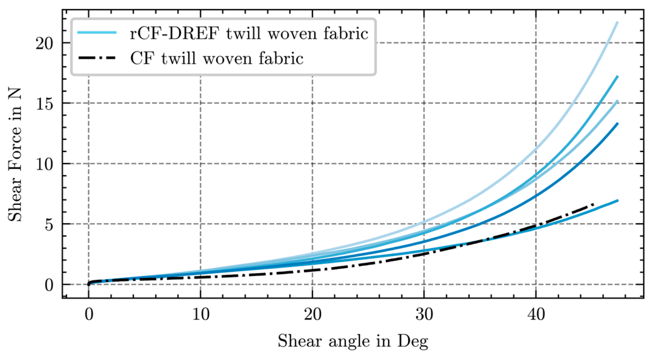
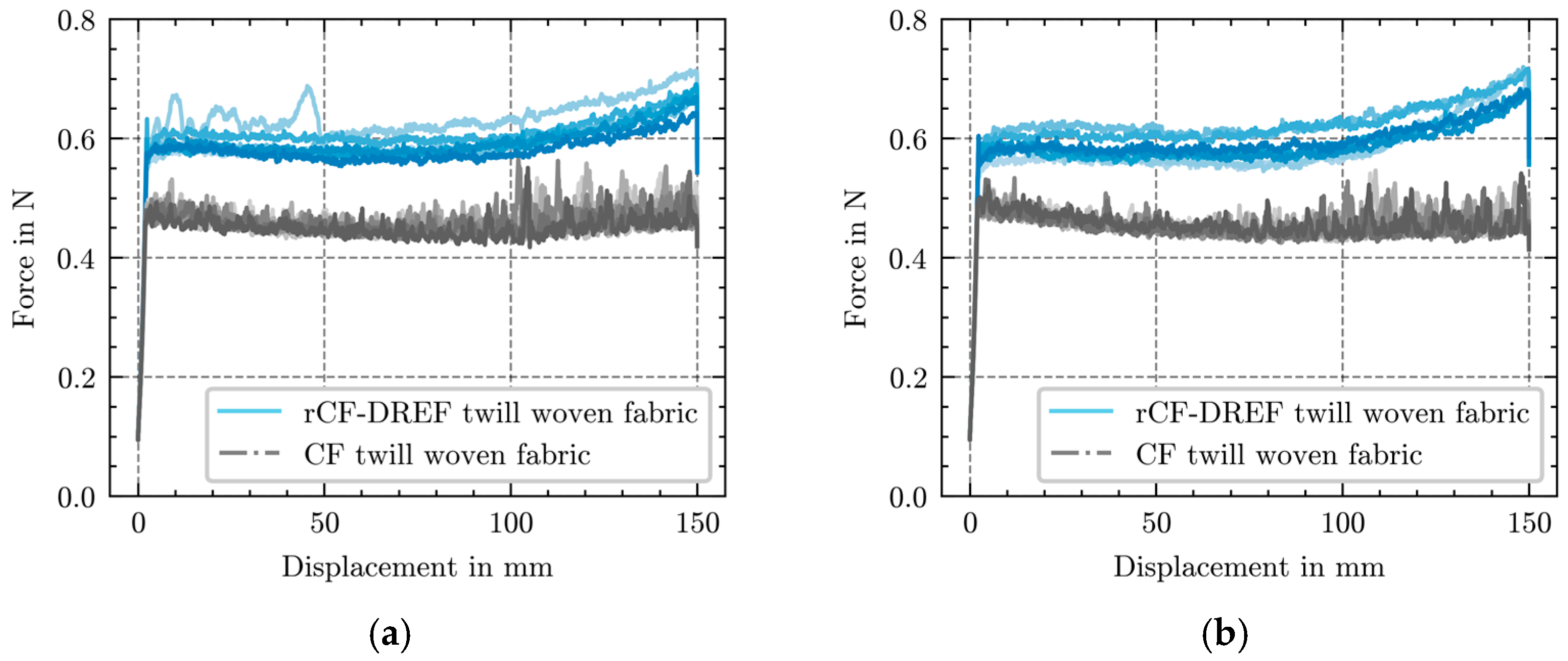
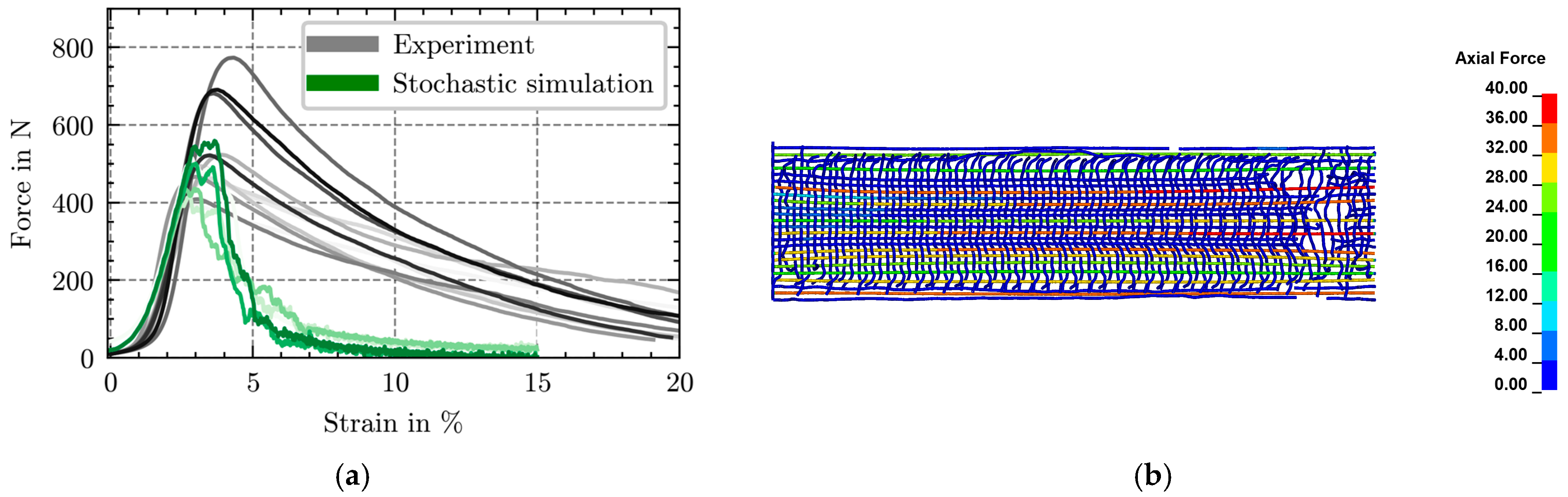
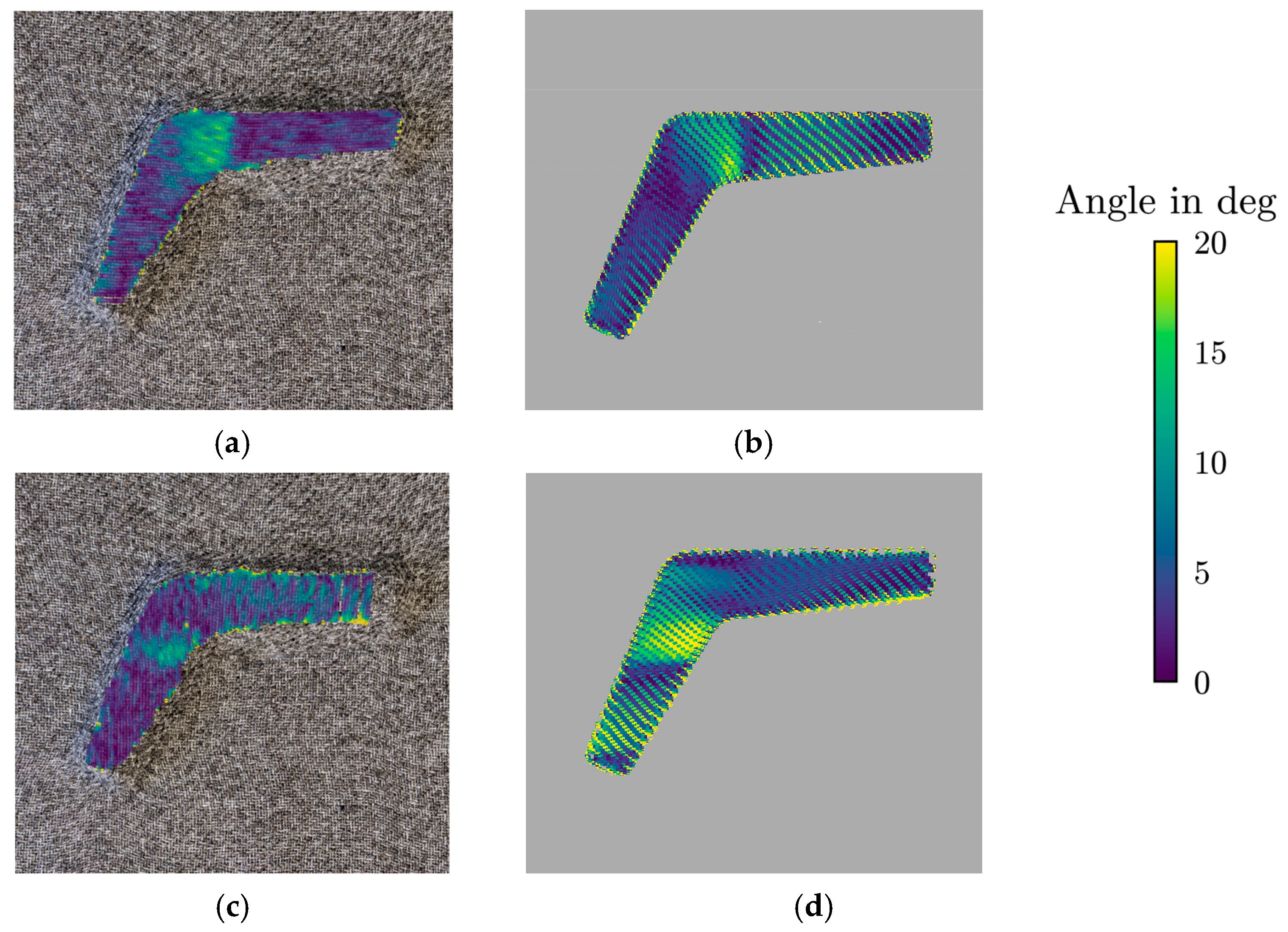
3.2. Simulation Results

Simulation models of the tensile test were carried out following the previously described approach. To identify stochastic properties, five distinct simulations were carried out. The results are depicted in Figure 15.
In comparison to the experiments, the simulation model showed some discrepancies in its post-peak behavior. In the simulation, brittle damage behavior could be observed in the yarns (Figure 15b).
This is due to differences in the tensile behavior of single yarns compared to yarns in woven fabric. As the post-peak behavior is also mainly influenced by frictional contacts in the core, perpendicular compression plays a vital role in the occurring frictional forces. During single-yarn tensile tests, the perpendicular compression in the yarn occurs only due to the axial elongation of the sheath fibers. In the fabric, perpendicular yarn-to-yarn contacts exist due to the interlacing of the yarns during the weaving process. When the textile is deformed in the plane in the warp or weft direction, the initially undulated yarns in the deformation direction are reoriented. During reorientation, contacts occur between the perpendicular weft or warp yarns, leading to a compression of the yarn cross-section in the contact vicinity. The compression of the yarn cross-section cannot be considered in the simulation model due to the idealistic assumptions of the employed beam elements.
To identify the effect, the post-peak behavior of the material was investigated. An overview of tensile test results under varied post-peak behavior is provided in Figure 16. By varying   E d e s c , a more ductile damage behavior, which is more consistent with the experiments, was achieved.
Based on the previous results, draping test simulations were carried out. Figure 17 shows the comparison between experimental and simulation results. On the top of the textiles, the fiber orientations with respect to the initial warp and weft directions are shown. Simulations show good agreement with the experiments in terms of shear angles.

4. Conclusions

It was shown that staple-fiber fabrics exhibit larger deformability in tension as well as higher shear forces compared to filament-based fabrics. Extensive fabric testing has shown the properties of twill-woven fabrics made from spun yarns. The new yarns, as well as the woven textiles based on them, exhibit higher ductility in tension in comparison to conventional filament-woven fabrics.
Modeling was carried out in parallel. A meso-scale model of woven fabrics with stochastic properties was established. Comparisons with experiments validated the approach up to the maximum load. After the maximum, a steeper decrease in the forces was observed in the simulations. These differences were attributed to perpendicular compressions on the yarn due to the woven structure. The perpendicular loads increased the friction in the yarn core during fiber-to-fiber slipping, forcing a smaller drop in forces. To improve the simulation results, a compression-dependent material model could be implemented in further studies. Nonetheless, the model can be used for further analyses of the draping process of fabrics made of staple fiber-spun yarns. Although the capabilities of rCF DREF-based fabrics have only been shown for 2/2 twill-woven fabrics, the high deformability of rCF yarns leads to much more benign failure behavior during formation compared to conventional filament-based fabrics. In the future, the use of these new yarns could not only promote the use of recycled carbon fibers in highly stressed components but also enable the low-waste production of complex geometries. Thereby, the production of recycled carbon fibers paves the way for further applications of thermoset carbon composites with high mechanical properties.

Author Contributions

Conceptualization, M.M.B.H. and T.G.L.; methodology, M.M.B.H. and T.G.L.; software, T.G.L.; validation, M.M.B.H. and T.G.L.; formal analysis, M.M.B.H. and T.G.L.; investigation, M.M.B.H. and T.G.L.; resources, M.M.B.H. and T.G.L.; data curation, M.M.B.H. and T.G.L.; writing—original draft preparation, T.G.L. and T.G.; writing—review and editing, M.M.B.H., A.A. and C.C.; visualization, T.G.L.; supervision, A.A., T.G. and C.C.; project administration, C.C., A.A. and T.G.; funding acquisition, T.G. and C.C. All authors have read and agreed to the published version of the manuscript.

Funding

This research was funded by the Deutsche Forschungsgemeinschaft (DFG, German Research Foundation)–442070201.

Data Availability Statement

The original contributions presented in this study are included in the article material. Further inquiries can be directed to the corresponding author.

Conflicts of Interest

The authors declare no conflicts of interest. The funders had no role in the design of the study; in the collection, analyses, or interpretation of data; in the writing of the manuscript; or in the decision to publish the results.

References

  1. Lightfoot, J.S.; Wisnom, M.R.; Potter, K. Defects in woven preforms: Formation mechanisms and the effects of laminate design and layup protocol. Compos. Part A Appl. Sci. Manuf. 2013, 51, 99–107. [Google Scholar] [CrossRef]
  2. Kulkarni, P.; Mali, K.D.; Singh, S. An overview of the formation of fibre waviness and its effect on the mechanical performance of fibre reinforced polymer composites. Compos. Part A Appl. Sci. Manuf. 2020, 137, 106013. [Google Scholar] [CrossRef]
  3. Sauer, M. Market Report 2024. 2025. Available online: https://composites-united.com/en/composites-united-market-report-2024-published-overview-of-the-current-composites-market-environment/ (accessed on 21 March 2025).
  4. Das, S. Life cycle assessment of carbon fiber-reinforced polymer composites. Int. J. Life Cycle Assess. 2011, 16, 268–282. [Google Scholar] [CrossRef]
  5. Arnold, U.; Palmenaer, A.d.; Brück, T.; Kuse, K. Energy-Efficient Carbon Fiber Production with Concentrated Solar Power: Process Design and Techno-economic Analysis. Ind. Eng. Chem. Res. 2018, 57, 7934–7945. [Google Scholar] [CrossRef]
  6. Liddell, H.; Brueske, S.; Carpenter, A.; Cresko, J. Manufacturing Energy Intensity and Opportunity Analysis for Fiber-Reinforced Polymer Composites and Other Lightweight Materials. In Proceedings of the American Society for Composites: 31st Technical Conference, Williamsburg, VA, USA, 19–22 September 2016. [Google Scholar]
  7. Suzuki, T.; Takahashi, J. LCA of Lightweight Vehicles by Using CFRP for Mass-Produced Vehicles. In Proceedings of the Fifteenth International Conference on Composite Materials, Durban, South Africa, 27 June–1 July 2005. [Google Scholar]
  8. Liddell, H.; Dollinger, C.; Fisher, A.; Brueske, S. Bandwidth Study on Energy Use and Potential Energy Saving Opportunities in U.S. Carbon Fiber Reinforced Polymer Manufacturing, United States. 2017. Available online: https://www.osti.gov/biblio/1513860 (accessed on 21 March 2025).
  9. Spini, F.; Bettini, P. End-of-Life wind turbine blades: Review on recycling strategies. Compos. Part B Eng. 2024, 275, 111290. [Google Scholar] [CrossRef]
  10. Beauson, J.; Laurent, A.; Rudolph, D.P.; Pagh Jensen, J. The complex end-of-life of wind turbine blades: A review of the European context. Renew. Sustain. Energy Rev. 2022, 155, 111847. [Google Scholar] [CrossRef]
  11. Goergen, C.; Schommer, D.; Duhovic, M.; Mitschang, P. Deep drawing of organic sheets made of hybrid recycled carbon and thermoplastic polyamide 6 staple fiber yarns. J. Thermoplast. Compos. Mater. 2020, 33, 754–778. [Google Scholar] [CrossRef]
  12. Goergen, C.; Baz, S.; Mitschang, P.; Gresser, G.T. Recycled carbon fibers in complex structural parts—Organic sheets made of rCF staple fiber yarns. KEM 2017, 742, 602–609. [Google Scholar] [CrossRef]
  13. Connor, M.L. Characterization of Recycled Carbon Fibers and Their Formation of Composites Using Injection Molding. Master Thesis, North Carolina State University, Raleigh, NC, USA, 2008. [Google Scholar]
  14. Stoeffler, K.; Andjelic, S.; Legros, N.; Roberge, J.; Schougaard, S.B. Polyphenylene sulfide (PPS) composites reinforced with recycled carbon fiber. Compos. Sci. Technol. 2013, 84, 65–71. [Google Scholar] [CrossRef]
  15. Wölling, J.; Schmieg, M.; Manis, F.; Drechsler, K. Nonwovens from Recycled Carbon Fibres—Comparison of Processing Technologies. Procedia CIRP 2017, 66, 271–276. [Google Scholar] [CrossRef]
  16. Abdkader, A.; Khurshid, M.F.; Hasan, M.M.B.; Cherif, C. Recent developments in yarn formation technology for producing innovative hybrid yarn structures from staple carbon and thermoplastic fibers for high-performance composites. J. Compos. Mater. 2023, 57, 1343–1362. [Google Scholar] [CrossRef]
  17. Ishikawa, T.; Amaoka, K.; Masubuchi, Y.; Yamamoto, T.; Yamanaka, A.; Arai, M.; Takahashi, J. Overview of automotive structural composites technology developments in Japan. Compos. Sci. Technol. 2018, 155, 221–246. [Google Scholar] [CrossRef]
  18. Rimmel, O.; May, D.; Goergen, C.; Poeppel, A.; Mitschang, P. Development and validation of recycled carbon fiber-based binder tapes for automated tape laying processes. J. Compos. Mater. 2019, 53, 3257–3268. [Google Scholar] [CrossRef]
  19. Akonda, M.H.; Lawrence, C.A.; Weager, B.M. Recycled carbon fibre-reinforced polypropylene thermoplastic composites. Compos. Part A Appl. Sci. Manuf. 2012, 43, 79–86. [Google Scholar] [CrossRef]
  20. Akonda, M.H.; EL-Dessouky, H.M.; Lawrence, C.A.; Weager, B.M. A novel non-crimped thermoplastic fabric prepreg from waste carbon and polyester fibres. J. Compos. Mater. 2014, 48, 843–851. [Google Scholar] [CrossRef]
  21. Wellekötter, J.; Baz, S.; Schwingel, J.; Gresser, G.T.; Middendorf, P.; Bonten, C. Recycling of composites—A new approach minimizes downgrading. AIP Conf. Proc. 2019, 2055, 60009. [Google Scholar] [CrossRef]
  22. Abdkader, A.; Bachor, S.; Hasan, M.M.B.; Cherif, C. Development of yarns from recycled carbon fiber based on friction spinning technology with specific properties for thermoset composites. Text. Res. J. 2024, 94, 12–23. [Google Scholar] [CrossRef]
  23. Goergen, C.; Baz, S.; Reichert, O.; Mitschang, P.; Gresser, G.T. Tiefziehbare Organobleche aus recycelten Carbonfasern. Z. Kunststofftechnik 2019, 15, 54–94. [Google Scholar] [CrossRef]
  24. Shehab, E.; Meiirbekov, A.; Amantayeva, A.; Tokbolat, S. Cost Modelling for Recycling Fiber-Reinforced Composites: State-of-the-Art and Future Research. Polymers 2022, 15, 150. [Google Scholar] [CrossRef]
  25. Leon, A.d.; Sweat, R.D. Interfacial Engineering of CFRP Composites and Temperature Effects: A Review. Mech. Compos. Mater. 2023, 59, 419–440. [Google Scholar] [CrossRef]
  26. Yu, H.; Potter, K.D.; Wisnom, M.R. A novel manufacturing method for aligned discontinuous fibre composites (High Performance-Discontinuous Fibre method). Compos. Part A Appl. Sci. Manuf. 2014, 65, 175–185. [Google Scholar] [CrossRef]
  27. Hasan, M.M.; Bachor, S.; Abdkader, A.; Cherif, C. Tensile properties of thermoset composites based on yarn structures from recycled carbon fibre and low melting temperature Co-polyamide fibre. J. Compos. Mater. 2024, 58, 55–64. [Google Scholar] [CrossRef]
  28. Wang, J.; Tayari Akankwasa, N.; Zhang, Y.; Shi, Q.; Li, L. The three-dimensional model of staple yarn formation simulated from randomly assembled fibers. Text. Res. J. 2020, 90, 866–876. [Google Scholar] [CrossRef]
  29. Deng, W.; Wang, X.; Ke, W.; Wang, C.; Deng, Z. Parametric 3D simulations of spun yarns and fabrics. J. Text. Inst. 2024, 115, 1413–1422. [Google Scholar] [CrossRef]
  30. Zhang, H.; Jabbar, A.; Li, A.; Wang, X.; Yang, D.; Tausif, M. Image-based finite element modelling of fibre dynamics in polyester staple spun yarns. Compos. Sci. Technol. 2025, 261, 111036. [Google Scholar] [CrossRef]
  31. Lang, T.G.; Hasan, M.M.B.; Abdkader, A.; Cherif, C.; Gereke, T. Micro-scale model of rCF/PA6 spun yarn composite. J. Compos. Sci. 2023, 7, 66. [Google Scholar] [CrossRef]
  32. Lang, T.G.; Hasan, M.M.B.; Abdkader, A.; Cherif, C.; Gereke, T. Micromechanical Modelling of the Deformation Mechanisms of Friction-Spun Yarn from Recycled Carbon Fibres. MSF 2024, 1117, 47–53. [Google Scholar] [CrossRef]
  33. Gereke, T.; Cherif, C. A review of numerical models for 3D woven composite reinforcements. Compos. Struct. 2019, 209, 60–66. [Google Scholar] [CrossRef]
  34. Wielhorski, Y.; Mendoza, A.; Rubino, M.; Roux, S. Numerical modeling of 3D woven composite reinforcements: A review. Compos. Part A Appl. Sci. Manuf. 2022, 154, 106729. [Google Scholar] [CrossRef]
  35. Döbrich, O.; Gereke, T.; Diestel, O.; Krzywinski, S.; Cherif, C. Decoupling the bending behavior and the membrane properties of finite shell elements for a correct description of the mechanical behavior of textiles with a laminate formulation. J. Ind. Text. 2013, 44, 70–84. [Google Scholar] [CrossRef]
  36. Boisse, P.; Colmars, J.; Hamila, N.; Naouar, N.; Steer, Q. Bending and wrinkling of composite fiber preforms and prepregs. A review and new developments in the draping simulations. Compos. Part B Eng. 2018, 141, 234–249. [Google Scholar] [CrossRef]
  37. Thompson, A.J.; Belnoue, J.P.-H.; Hallett, S.R. Modelling defect formation in textiles during the double diaphragm forming process. Compos. Part B Eng. 2020, 202, 108357. [Google Scholar] [CrossRef]
  38. Chen, B.; Colmars, J.; Naouar, N.; Boisse, P. A hypoelastic stress resultant shell approach for simulations of textile composite reinforcement forming. Compos. Part A Appl. Sci. Manuf. 2021, 149, 106558. [Google Scholar] [CrossRef]
  39. Boisse, P.; Akkerman, R.; Carlone, P.; Kärger, L.; Lomov, S.V.; Sherwood, J.A. Advances in composite forming through 25 years of ESAFORM. Int. J. Mater. Form. 2022, 15, 39. [Google Scholar] [CrossRef]
  40. Sun, X.; Belnoue, J.P.-H.; Thompson, A.; Said, B.E.; Hallett, S.R. Dry Textile Forming Simulations: A Benchmarking Exercise. Front. Mater. 2022, 9, 831820. [Google Scholar] [CrossRef]
  41. Boisse, P.; Hamila, N.; Madeo, A. Modelling the development of defects during composite reinforcements and prepreg forming. Philos. Trans. R. Soc. A Math. Phys. Eng. Sci. 2016, 374, 20150269. [Google Scholar] [CrossRef] [PubMed]
  42. Coutandin, S.; Brandt, D.; Heinemann, P.; Ruhland, P.; Fleischer, J. Influence of punch sequence and prediction of wrinkling in textile forming with a multi-punch tool. Prod. Eng. Res. Devel. 2018, 12, 779–788. [Google Scholar] [CrossRef]
  43. Döbrich, O.; Gereke, T.; Cherif, C. Modeling the mechanical properties of textile-reinforced composites with a near micro-scale approach. Compos. Struct. 2016, 135, 1–7. [Google Scholar] [CrossRef]
  44. Döbrich, O.; Gereke, T.; Hengstermann, M.; Cherif, C. Microscale finite element model of brittle multifilament yarn failure behavior. J. Ind. Text. 2018, 47, 870–882. [Google Scholar] [CrossRef]
  45. Daelemans, L.; Faes, J.; Allaoui, S.; Hivet, G.; Dierick, M.; van Hoorebeke, L.; van Paepegem, W. Finite element simulation of the woven geometry and mechanical behaviour of a 3D woven dry fabric under tensile and shear loading using the digital element method. Compos. Sci. Technol. 2016, 137, 177–187. [Google Scholar] [CrossRef]
  46. Teijin Limited. Tenax Filament Yarn: Product Data Sheet. 2024. Available online: https://dragonplate.com/images/uploaded/pdfs/fiberspecs/filament-product_programm__eu__v27_2018-06-27_en.pdf (accessed on 21 March 2025).
  47. Orawattanasrikul, S. Experimentelle Analyse der Scherdeformationen Biaxial Verstärkter Mehrlagengestricke. Ph.D. Thesis, TU Dresden, Dresden, Germany, 2006. [Google Scholar]
  48. Taha, I.; Abdin, Y.; Ebeid, S. Comparison of picture frame and Bias-Extension tests for the characterization of shear behaviour in natural fibre woven fabrics. Fibers Polym. 2013, 14, 338–344. [Google Scholar] [CrossRef]
  49. Nosrat Nezami, F.; Gereke, T.; Cherif, C. Analyses of interaction mechanisms during forming of multilayer carbon woven fabrics for composite applications. Compos. Part A Appl. Sci. Manuf. 2016, 84, 406–416. [Google Scholar] [CrossRef]
  50. Andrade, F.X.C.; Feucht, M.; Haufe, A.; Neukamm, F. An incremental stress state dependent damage model for ductile failure prediction. Int. J. Fract. 2016, 200, 127–150. [Google Scholar] [CrossRef]
Figure 1. Force–strain behavior of (a) rCF-DREF 800 tex and (b) rCF-DREF 1600 tex yarns; colors represent test of individual yarns.
Jcs 09 00173 g001
Figure 2. Manufacturing of woven fabric using rCF yarn: (a) creeling, (b) shading, and (c) take-up process.
Jcs 09 00173 g002
Figure 3. Top views of manufactured twill-woven fabrics with (a) 800 tex yarns and (b) 1600 tex yarns.
Jcs 09 00173 g003
Figure 4. Peformed tests of woven fabrics: (a) tensile test, (b) cantilever bending test, and (c) picture frame shear test.
Jcs 09 00173 g004
Figure 5. Draping test setup for boomerang geometry: (a) configuration of blank holders and (b) experimental setup.
Jcs 09 00173 g005
Figure 6. Geometry of rCF-DREF 800 tex twill-woven fabric: (a) micrograph and (b) model after compaction step.
Jcs 09 00173 g006
Figure 7. Cumulative distribution of exponential Weibull for maximum stress.
Jcs 09 00173 g007
Figure 8. Validation of material model of rCF-DREF 800 tex yarn tensile test; experiments are shown in different shades of gray, simulations are shown in different shades of green, different color shades represent tests and simulations of individual yarns, respectively.
Jcs 09 00173 g008
Figure 9. Tensile simulation test setup.
Jcs 09 00173 g009
Figure 10. Draping simulation test setup.
Jcs 09 00173 g010
Figure 11. Force–strain behavior of rCF-DREF 800 tex twill-woven fabric in (a) warp and (b) weft direction; colors represent test of individual fabrics.
Jcs 09 00173 g011
Figure 12. Shear response curves of rCF-DREF 800 tex and CF 800 tex twill-woven fabric.
Jcs 09 00173 g012
Figure 13. Friction test curves in (a) warp and (b) weft direction.
Jcs 09 00173 g013
Figure 14. Twill-woven fabric after draping (blank holder forces): (ac) 0 N; (df) 20 N: (a,d) top view; (b,e) detailed view of right nose; and (c,f) detailed view of bend.
Jcs 09 00173 g014aJcs 09 00173 g014b
Figure 15. Simulation of tensile test of rCF-DREF 800 tex twill-woven fabric in warp direction: (a) force–strain curves and (b) axial forces in the beam elements at 6% strain; in (a): experiments are shown in different shades of gray, simulations are shown in different shades of green, different color shades represent tesst and simulations of individual yarns, respectively.
Jcs 09 00173 g015
Figure 16. Tensile test results with varied E d e s c : (a) −11.5 MPa; (b) −8 MPa; (c) −6 MPa; and (d) −4 MPa; experiments are shown in different shades of gray, simulations are shown in different shades of green, different color shades represent tests and simulations of individual yarns, respectively.
Jcs 09 00173 g016
Figure 17. Yarn orientation after draping (blank holder forces 20 N): (a) experiment warp, (b) simulation warp, (c) experiment weft, and (d) simulation weft.
Jcs 09 00173 g017
Table 1. Tensile properties of the fiber materials used for yarn production as mean value (standard deviation).
Type of FiberFiber LengthLinear DensityDiameterTensile StrengthYoung’s ModulusElongation at Break
(mm)(dtex)(μm)(cN/Tex)(MPa)(GPa)(%)
rCF60 (5)0.5 (0.1)5.8 (3.0)220.0 (55.6)3868 (1368)268.9 (59.6)1.6 (0.3)
Co-polyamide 100 (2)11.2 (0.6)36.6 (8.8)25.1 (1.8)268 (20)0.5 (0.1)147.9 (13.9)
Table 2. Tensile properties of the yarns used for fabric production as mean value (standard deviation), N = 30.
Type of YarnFmax (N)Elongation at Fmax (%)Elongation at Break (%)
rCF-DREF 800 tex23.4 (7.9)1.74 (0.31)9.96 (3.58)
rCF-DREF 1600 tex 37.6 (10.6)2.64 (0.43)12.26 (3.77)
CF roving 800 tex [46] 20111.81.8
CF roving 1600 tex [46]40221.81.8
Table 3. Parameters for the exponential Weibull distribution of maximum yarn stress.
Parameterak λ Location
Value4.8780.9345.5497.692
Table 4. Tensile properties of the twill-woven fabrics as mean value (standard deviation).
Type of YarnTest DirectionFmax (N)Elongation at Fmax (%)Elongation at Break (%)
rCF-DREF 800 texWarp direction528.4 (120.9)3.40 (0.43)22.63 (4.17)
Weft direction 558.2 (95.3)8.71 (1.55)27.02 (2.25)
CF 800 texWarp direction10,278.8 (300.5)0.95 (0.10)-
Weft direction 9414.2 (745.6)1.04 (0.16)-
Table 5. Cantilever test results of rCF-DREF 800 tex twill-woven fabric as mean value (standard deviation).
DirectionOverhang Length (mm)Bending Stiffness (mN cm)
Warp157.6 (11.3)291.4 (53.4)
Weft 137.2 (4.5)188.4 (19.3)
Table 6. Friction test results of rCF-DREF and CF 800 tex twill-woven fabric to steel as mean value (standard deviation).
DirectionStatic Friction CoefficientDynamic Friction Coefficient
rCF Warp0.312 (0.015)0.306 (0.010)
rCF Weft 0.305 (0.008)0.307 (0.010)
CF Warp0.255 (0.008)0.233 (0.003)
CF Weft 0.261 (0.005)0.232 (0.001)
Disclaimer/Publisher’s Note: The statements, opinions and data contained in all publications are solely those of the individual author(s) and contributor(s) and not of MDPI and/or the editor(s). MDPI and/or the editor(s) disclaim responsibility for any injury to people or property resulting from any ideas, methods, instructions or products referred to in the content.

