Article

Axial Compressive Behavior of CFRP and MWCNT Incorporated GFRP Confined Concrete Cylinders after Exposure to Various Aggressive Environments

by
Sruthi Sreekumar Kavitha
1,2,
Mini K. Madhavan
3,*,
Karingamanna Jayanarayanan
1,2,* and
Prabir Kumar Sarker
4
1
Department of Chemical Engineering and Materials Science, Amrita School of Engineering, Amrita Vishwa Vidyapeetham, Coimbatore 641 112, India
2
Center of Excellence in Advanced Materials and Green Technologies (CoE-AMGT), Amrita School of Engineering, Amrita Vishwa Vidyapeetham, Coimbatore 641 112, India
3
Department of Civil Engineering, Amrita School of Engineering, Amrita Vishwa Vidyapeetham, Coimbatore 641 112, India
4
Civil Engineering Discipline, School of Civil and Mechanical Engineering, Curtin University, Perth, WA 6102, Australia
*
Authors to whom correspondence should be addressed.
J. Compos. Sci. 2024, 8(8), 313; https://doi.org/10.3390/jcs8080313
Submission received: 24 July 2024 / Revised: 2 August 2024 / Accepted: 6 August 2024 / Published: 9 August 2024

Abstract

Fiber-reinforced polymer confinement is considered to be effective in the retrofitting of concrete structures. The current study explores the effectiveness of one- and two-layer carbon fiber reinforced polymer (CFRP) and multiwalled carbon nanotube (MWCNT) incorporated three-layer glass fiber reinforced polymer (GFRP) confinement on concrete cylinders under aggressive exposures, such as acid, alkaline, marine, water, and elevated temperatures. At 1 wt.% MWCNT by weight of the epoxy matrix, mechanical characteristics of the laminate show a significant improvement. In the case of acid exposure, the axial load-carrying capacity of concrete specimens with single-layer CFRP confinement was equal to that of MWCNT incorporated three-layer GFRP confinement (GF3C1-AC). The axial strain of GF3C1-AC was 23% and 12% higher than one and two-layer CFRP confinement. After exposure at 400 °C, in comparison with one- and two-layer CFRP confinement, the axial strain of MWCNT incorporated three-layer GFRP confined specimens increased by 50% and 20%, respectively, which proved the efficacy of MWCNT as a heat-resistant nanofiller. The ultrasonic pulse velocity (UPV) test indicates that the confinement system protects the concrete core from sudden failure by impeding crack propagation. The test results proved that the MWCNT incorporated FRP system can be considered as a prospective substitute for CFRP systems for retrofitting applications in severe environmental conditions.

1. Introduction

Structural members used in the construction sector are prone to aggressive environmental impacts, which can affect their performance during service life. Retrofitting is a process of modifying the existing structure to improve its performance, functionality, safety, and energy efficiency [1]. Retrofitting and maintenance of concrete structures help to increase the load-carrying capacity, durability, and resistance to various environmental factors. Retrofitting and rehabilitation using fiber-reinforced polymer (FRP) as an external jacket are considered as an effective approach for prolonging the service life of structural members [2]. FRPs are light in weight, resistant to corrosion, economical, and offer high tensile properties which makes them a practical solution for the deterioration problems in the infrastructure industry. Many investigations [3,4,5,6] proved that proper design and installation of FRP ensure the effectiveness, lifespan, and performance of structural elements. Confinement improves the contact area between FRP and concrete surface, distributing the load uniformly. The widespread use of the FRP system might also be related to its cost-effectiveness and maintenance compared to other methods [7].
The reinforcement phase of the FRP system includes various types of natural and synthetic fibers, which contribute to the flexural, toughness, and overall performance of the composites. One of the traditional reinforcement techniques is the use of carbon fiber reinforced polymer (CFRP), which has an exceptionally high tensile strength and modulus of elasticity. However, carbon fiber is very expensive in comparison with other fibers and attempts are being made to analyze the application of fibers, including glass [8], sisal [9], basalt [10], etc. Pan and Yan [11] reported the considerable enhancement in the confinement effectiveness of CFRP. However, due to the high cost of carbon fiber, confinement was limited to two layers. Weiwen Li [12] carried out a study on the failure behavior of partially confined CFRP on ultra-high-performance concrete. The confinement was limited due to the high cost of carbon fiber. Economic comparison of carbon and glass fiber confined concrete cylinders was studied by Haj Seiyed [13]. Here, samples were subjected to compressive testing and test results revealed that carbon and glass fibers improved the compressive strength and seismic properties of concrete. However, economic research suggested that glass fiber is more cost-effective than carbon fiber in improving the concrete qualities, especially for one layer of FRP. Glass fiber reinforced polymer (GFRP) is an excellent material for the infrastructure sector because of its high tensile strength and low thermal conductivity [14]. According to the extensive literature review, it is evident that the construction industry is on the quest for the replacement of expensive CFRP with suitable alternate materials for the strengthening of concrete structures.
Epoxy resin is utilized as a matrix material in FRP systems owing to its excellent tensile properties, strength-to-weight ratio, and chemical stability. Epoxy degrades during its service life due to harsh environmental conditions, resulting in a decline in the thermomechanical characteristics of the FRPs produced. Incorporation and better diffusion of nanofillers in the FRP systems can improve the performance of composites. Numerous studies [15,16] have reported the effect of adding multi-walled carbon nanotubes (MWCNTs) in the thermomechanical attributes of the composites. MWCNTs consist of multiple layers of graphene arranged concentrically which have unique properties due to their nanoscale structure. The outcomes of these studies revealed that the integration of MWCNTs into the epoxy matrix and using them with various FRP systems enhanced the tensile strength, fracture toughness, flexural properties, and Young’s modulus. The uniform distribution of MWCNTs is the primary contributor to the excellent mechanical characteristics. When the MWCNTs percentage is high, nanoparticle aggregation occurs due to the van der Waals forces of attraction, causing a reduction in the desired properties [17]. The presence of fiber and nanofiller in multiscale composites can significantly inhibit crack propagation and bendability [18]. Beyond the optimal percentage, the resistance of crack propagation decreased due to agglomeration. Studies discovered that epoxy multiscale composites improved the axial load-carrying capacity of confinement [19]. Wahab and Hussain conducted a study on the functionality of concrete structures wrapped with a jute–polyester hybrid fiber-reinforced polymer (JPHFRP) composite [20]. Lower-strength specimens with round sections had a substantial effect on wrapping. Polyester jackets affect the peak stress–strain behavior of high-strength specimens due to their high rupture strain. Various studies proved that ductile behavior and fracture energy were greatly enhanced by FRP wrapping and varied substantially with the number of FRP layers and MWCNT alteration [21].
In addition to the mechanical properties, the durability characteristics of confined and unconfined concrete specimens exposed to harmful environments were also studied [22]. In recent decades, extensive studies have been conducted on the long-term behavior of fiber-reinforced polymers. The external elements that impact FRP’s durability are high temperature, moisture, alkali, acid, salt, temperature, stress, fatigue, and UV radiation [23]. The application of FRP has been restricted owing to the unpredictability of its behavior in high-temperature conditions and that it releases harmful gases under such circumstances. Researchers looked at the effectiveness of confined concrete cylinders subjected to high temperatures compared to unconfined cylinders [24]. Limited studies have been carried out on FRP-confined concrete structures at elevated temperatures. While some fiber types may withstand harsh environments, the FRP system’s matrix is likely to degrade as a result of these exposures. Several artificial fibers like carbon fiber can withstand temperatures up to 800 °C; however, due to the involvement of the epoxy matrix, a significant decrease in characteristics was experienced [25]. The mechanical attributes of FRP composite at extreme temperatures depend considerably on the properties of the matrix material [26]. Polymer resin weakens at temperatures around its glass transition temperature (Tg), restricting stress transfer between fiber and matrix. It is reported that the mechanical properties of FRP composites degrade rapidly at Tg of their constituent resin. FRP-confined concrete cylinders deteriorate quickly with increasing temperature, finally causing the delamination of FRP from the concrete structure [27]. Concrete structures manufactured with ordinary Portland cement concrete rapidly react with attacking acids, lose their strength, and are damaged quickly [28]. An evaluation of the impact of seawater on the ductility and compressive strength of concrete cylinders [29] revealed that FRP material can be employed as a retrofit material for structural elements in marine environments. Several studies [30,31] were conducted to assess the effect of sulfate resistance on confined and unconfined concrete cylinders. The outcomes of the studies were important for the cylinders exposed to sulfate attack and the system can be adopted to improve the service life of structures.
A different approach to CFRP retrofitting is required, as indicated by the extensive literature survey. Confinement using multi-walled carbon nanotube (MWCNT) incorporated GRFP is considered an effective technique, which is yet to be documented, to the best of the authors’ knowledge. The study utilizes epoxy as a matrix for concrete cylinder confinement and examines the mechanical and durability characteristics of CFRP, GFRP, and multi-walled carbon nanotube (MWCNT) incorporated GRFP. The effectiveness of the single and double-layer CFRP confinement systems is evaluated, and the outcomes are compared with the three-layer GFRP incorporated MWCNT system. The uniform dispersion of nanofiller can be ascertained from transmission electron microscopy and mechanical properties of composite laminates are being evaluated from tensile properties analysis. Ultimate compressive stress and strain of concrete specimens confined using different FRP systems subjected to varied environmental situations are studied and the failure patterns are identified.

2. Materials and Methods

2.1. Materials

The concrete is prepared according to IS 10262-2009 [32]; the mix proportions of cement, fine aggregate, and coarse aggregate were set at 1:1.5:2.58 with a water-to-cement ratio of 0.45 to obtain a target strength of 25 MPa. The specifications of materials utilized in the concrete mix are listed in Table 1.
Bi-directional carbon fiber and glass fiber (plain W1-A E) of 200 g/m2 procured from Go Green Products, India were employed for the study. The tensile strength and modulus of carbon fabric were 5516 MPa and 250 GPa, respectively. Glass fiber has a tensile strength of 3448 MPa and modulus of 72 GPa. The elongation at break of carbon fiber and glass fiber was 4.7% and 2.2%, respectively.
In FRP, epoxy resin serves as the binding agent. For the two-part system, hardener (HY991) and resin (LY556) were purchased from Covai Seenu Products, India. To produce a consistent mix, the manufacturer suggested mixing the ingredients in a ratio of 100:15.
The MWCNT treated with carboxylic acid (-COOH) with a 97% purity was acquired from Platonic Nano Tech Private Ltd., Jharkhand, India. Based on information supplied by the provider, the length varied from 2 to 10 μm, the outside diameter was between 5 and 20 nm, and the specific surface area was between 250 and 270 m2/g.

2.2. Methods

2.2.1. FRP Composite Preparation

Different compositions of epoxy nanocomposites and multiscale composites were prepared using the hand lay-up method. The required quantity of MWCNT was uniformly dispersed in the epoxy resin using an ultrasonic probe sonicator set to 20 kHz for 30 min. The hardening agent was mixed with the sonicated resin system following the manufacturer’s instructions, maintaining a consistent weight ratio of 15 parts hardening agent to 100 parts epoxy resin. The epoxy–MWCNT nanocomposites were made using several weight percentages of the nanofiller by the weight of epoxy, namely 0.5 wt.%, 1 wt.%, 1.5 wt.%, and 2 wt.%, in order to maximize the MWCNT content [33]. The nanocomposite slabs prepared by the hand lay-up method were allowed to cure at room temperature for 72 h.

2.2.2. Confinement of FRP on the Cylindrical Concrete Specimen

FRP-confined concrete cylinders with dimensions of, 100 mm diameter and 200 mm height were prepared using M25 grade concrete. Two types of matrix systems were used in the study, neat epoxy matrix and MWCNT incorporated epoxy matrix. Carbon fiber and glass fiber were cut to specific dimensions. Confinement details of each fiber system are explained in Section 2.2.3.
Before wrapping, surface roughening was carried out on concrete cylinders to improve the adhesion of FRP with concrete substrate. The required amount of epoxy resin was mixed with hardener along with a sufficient quantity of MWCNT, and an initial coat was applied to the cylinder surface. To provide a confinement effect, resin-impregnated fiber was wrapped around the radial surface in the hoop direction. To avoid direct axial loading on the confinement, a 20 mm gap was left at the top and bottom of the cylinder during wrapping. Air pockets were removed from the FRP layers by exerting uniform pressure with a roller. The confined cylinders were then allowed to cure at room temperature for seven days [4,34].

2.2.3. Test Specimens

A total of 120 cylinders with circular cross-sections of 100 mm diameter and 200 mm height were prepared. For the investigation, five specimens from each composition of epoxy–nano and epoxy–multiscale composites were tested. The nomenclature of each specimen exposed to various environmental conditions is given in Table 2. ‘CS’ denotes the control specimen, and ‘N’, ‘AC’, ‘AL’, ‘M’, and ‘W’ denote normal condition, acid, alkaline, marine, and water, respectively. ‘CF’ and ‘GF’ signify carbon fiber and glass fiber, respectively, with the suffix indicating the number of layers used for the laminates. The numbers 100 to 400 denote the range of temperature exposure.

2.2.4. Durability Studies

Different sets of FRP-confined and unconfined concrete cylinders were exposed to various environmental conditions prior to uniaxial compressive strength testing in order to assess their durability characteristics [35]. Five samples from each composition listed in Table 2 were exposed to acid, alkaline, marine, and water environments for 120 days, and in elevated temperature conditions up to 400 °C [36]. Following ASTM C267 test requirements, the specimens were submerged in a 5% sulfuric acid solution per liter of water to establish an acidic environment. The marine habitat was established by immersing the specimens in a 3.5% NaCl solution per liter of water, while an alkaline atmosphere was produced using a 7% solution of NaOH per liter of water [37]. Schematic illustrations of FRP preparation, confinement, and durability exposure are given in Figure 1.

3. Results

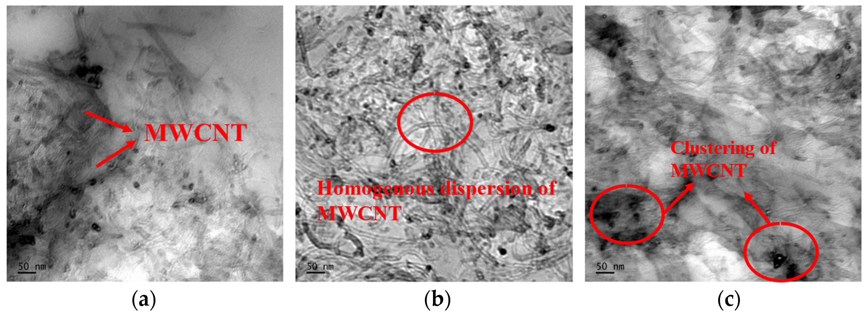
3.1. Morphology and Mechanical Properties of Composite Laminates

Transmission electron microscopy (TEM) is a highly efficient method for examining the morphology, dispersion, and particle size of nanofillers. TEM images of epoxy–MWCNT nanocomposites of varied weight percentages of the MWCNTs, especially 0.5 wt.%, 1 wt.%, and 1.5 wt.%, are shown in Figure 2. The uniform dispersion of nanofiller is only evident in certain spots at 0.5 wt.% because of the low quantity of MWCNTs in the polymer matrix [38]. The homogeneous nanoparticle dispersion and the CNTs’ capacity to retain their tubular shape even after sonication is evident in the microstructure of the 1 wt.% CNT dispersed samples [39]. The morphology of 1.5 wt.% clearly shows that the nanoparticles are clustered in various places. At 1.5 wt.%, agglomerates develop as a result of the interparticle van der Waals forces [40]. The aggregation of nanofillers may result in a very low interparticle distance between the nanoparticles [41].
According to composite theory, the tensile performance of the composite is primarily achieved by the reinforcing fibers. Tensile properties of epoxy–nano and epoxy–multiscale composites are studied as per ASTM D638 [42] and listed in Table 3. The nomenclature used here is such that, ‘E’ is epoxy and ‘C’ represents the nanofiller (MWCNT) with a suffix indicating the percentage of MWCNT utilized. Based on the observed results, the tensile properties of the composite laminates improved significantly with the addition of MWCNTs [43]. The effective load transfer was achieved by the uniform dispersion of nanoparticles, further contributing to the improvement of laminates’ mechanical characteristics. At higher weight percentages of nanoparticles, agglomerates are formed due to low interparticle distance and affect the tensile properties of composites [44]. Accordingly, in multiscale composites, the nanofiller content was maintained at 1 wt.%. The multiscale composite, a three layer glass fiber with 1 wt.% of MWCNT integrated epoxy (EC1GF3) laminates were made and compared with one and two layers of carbon fiber laminates (ECF1 and ECF2), and three layers of GFRP (EGF3) laminates.
A noticeable ductile behavior was displayed by multiscale composites, manifested by their significant elongation before failure. In comparison to the EGF3 laminate, the EC1GF3 laminate demonstrated a 32% increase in tensile strength and a 60% increase in Young’s modulus. At higher weight percentages, the tensile properties were reduced due to the coalescence of the nanofiller. In multiscale composites, mechanical interlocking creates a bridge effect by transferring stress from low-modulus matrix material to high-modulus MWCNTs [45]. Thus, the incorporation of MWCNTs helped to improve the tensile characteristics of composites. The optimum MWCNT content was found at 1 wt.%, where uniform dispersion of MWCNTs is visible and is considered as the optimum weight percentage of nanofiller for the confinement process.

3.2. Axial Compressive Behavior

The compressive strength of confined concrete specimens was evaluated using a uniaxial compression test following ASTM C39 [46]. Linear variable differential transducers (LVDTs) attached to the specimens were utilized to measure axial deformations, and related stress versus strain graphs were plotted. Table 4 displays the compressive test results of concrete cylinders jacketed with various composite systems. The confinement effectiveness ratio is expressed as f′cc/f′co, where f′co and f′cc are the compressive strengths of confined and unconfined cylinders, respectively. Axial strain is denoted as ε′co for unconfined specimens and ε′cc for confined examples. Carbon fiber in varying layers (one to two) and glass fiber in three layers were confined to the concrete cylinders. The test results demonstrated that the FRP-confined specimen’s compressive strength and ductility were improved significantly. When a load is applied, cracks propagate with small characteristic noises, and then they collapse with an explosive sound at the point of failure to signify the rupture of the FRP [34]. A different break pattern was noticed for the cylinder confined with MWCNT incorporated three-layer GFRP systems and a notable confinement effect was exhibited as a primary factor in the increased load-bearing capacity. When the load was applied, the inner FRP layer tended to rupture first and the outer layer remained resilient. It was found that specimens with single-layer CFRP confinement had an axial load-bearing capacity that was equivalent to specimens with 1 wt.% MWCNT incorporated three-layer GFRP wrapping. GF3C1-N exhibited 15% greater axial compressive strength than GF3-N. On the other hand, GF3C1-N confined specimens showed an improvement in the strain capacity as compared to CF1-N and CF2-N. GF3C1-N confined specimens had an axial strain that was 75% greater than CF1-N and 12% greater than CF2-N. The strength of GF3C1-N specimens was found to be 42% stronger than that of GFRP confined specimens, with a confinement effectiveness of 1.4. The inclusion of MWCNTs considerably boosted the strength of confined cylinders. The mechanical interaction of the nanotubes and polymer chains is responsible for the transfer of stress from low-modulus epoxy material to high-modulus MWCNT material [47].
The stress–strain behavior of both confined and unconfined concrete cylinders is demonstrated in Figure 3. The brittle nature of concrete caused unconfined concrete specimens to fail at the first stage. Due to the ductility provided by FRP, the confined specimens fail after yielding. The unconfined specimens’ stress–strain curves showed a single linear regime, while the FRP-confined specimens exhibited a distinct trend [3]. The stress–strain curve in confined specimens initially resembled that of unconfined specimens. FRP wrapping has a negligible effect in the initial phase of loading due to the minimal lateral distortion of the concrete core. The stress produced at the maximum compressive load led to the emergence of tiny cracks and a transitional zone was formed [48]. When the maximum compressive strength is reached, a confinement effect is manifested in the next phase of the stress–strain curve. Unconfined specimens failed at the early stage due to their brittle nature; however, FRP laminate provides the confinement effect during the transition period, and the second stage has a telling effect due to the combined qualities of concrete and FRP. The inclusion of 1 wt.% MWCNT in the matrix resulted in increased axial strain and considerable plastic deformation before failure. Furthermore, the transition zone in GF3C1-N stress–strain curves is similar to that of the GFRP confined specimen [49,50]. FRP and nanofillers improved the axial load-bearing capabilities of concrete cylinders and their compressive strength. The compressive strength of the confined cylinder depends on the fiber/fabric strength and the interfacial bond between epoxy and fiber, as well as epoxy and concrete [51].

3.3. Effect of Acid Exposure

The specimens were submerged in a 5% sulfuric acid solution per liter of water to create an acidic environment. Confined and unconfined concrete cylinders were completely immersed in the acidic solution and kept for 120 days. Table 5 represents the compressive strength and axial strain of specimens exposed to the acid environment. Deterioration and change in the appearance of the concrete surface were observed during the exposure period. Specimens were cleaned and dried after the exposure period to remove any chemical reaction products from their surface. From Figure 4, it is evident that the color of unconfined specimens was changed to yellow. Due to surface etching, the texture of the concrete surface was roughened and affected the visual appearance of the cylinders. The acid present in the solution reacted with the calcium hydroxide in the concrete and reduced the strength of the concrete. During visual inspection, a white, powdery substance appeared on the concrete cylinder’s surface. This formation was caused by efflorescence, which decreases the structure’s strength and durability of concrete specimens [28]. Concrete is susceptible to attack by acids due to the highly alkaline nature of Portland cement. Sulfuric acid is particularly aggressive due to the sulfate ion participating in the reaction, in addition to the dissolution caused by the hydrogen ion. Sulfur compounds are formed as a result of the sulfuric acid–cement paste reaction, which accelerates the disintegration of the concrete [52,53]. The axial compressive strength of the acid-exposed concrete cylinder was 7 MPa. FRP confinement was essential in preventing acid exposure damage to concrete cylinders. When a compressive force was applied, tiny cracks appeared on top of the FRP, and the FRP layers ruptured, causing the concrete core to collapse. FRP materials are resistant to acids due to the chemical inertness of the polymer matrix and reinforcing fibers. The presence of FRPs prevents the acid penetration to the concrete substrate and reduces the degradation to a large extent. Confinement using one layer of CFRP wrapping improved the compressive strength to 29.6 MPa.
The addition of one more layer improved the properties of concrete cylinders significantly. Comparing GFRP-wrapped specimens to unconfined specimens, the compressive strength of the former increased to 25.6 MPa. In the case of MWCNT integrated GFRP wrapped specimens, the compressive strength increased to 29.9 MPa. The composite material’s ability to withstand acidic conditions was augmented by the addition of nanofillers. On comparing GF3C1-AC with GF3C1-N, the percentage drop was approximately 5%, which indicates the resistance offered by MWCNTs. Hence, when compared to unconfined specimens, the performance of MWCNT incorporated GFRP confined specimens was excellent, exhibiting a great resistance against acid attack [31].
The stress–strain curve of FRP-confined systems exposed to the acidic environment is exhibited in Figure 5. The ultimate axial strain of confined specimens was higher compared to unconfined specimens. The axial strain of MWCNT incorporated GFRP confinement was 23% and 12% higher than one-layer and two-layer CFRP confinement, respectively. With respect to unconfined specimens, multiscale FRP confinement could significantly yield prior to failure even in severe environmental circumstances.

3.4. Effect of Alkaline Exposure

An alkaline environment was created using a 7% NaOH solution per liter of water. For a period of four months, both confined and unconfined concrete cylinders were completely submerged in the prepared solution. A small layer of efflorescence was noticed on the outermost surface of the cylinders. Even after 120 days, the outer layer of wrapped FRPs remained intact. Minor deterioration started on the surface of the concrete and continued to the inner core of the specimens. The influence of NaOH exposure on the specimens confined with FRP was found to be less than unconfined specimens due to the inherent high resistance of carbon and glass fiber to alkaline attack. Alkaline exposure has a minor effect on the FRP due to the sensitive nature of the epoxy matrix. During the early loading stages, the gradual rupture of FRP fabrics occurs with a sudden loud noise that was immediately followed by a pre-failure cracking noise. Failure started at the middle portion of the specimen where the FRP fabrics overlapped and then spread to the top and bottom portions of the specimens. The presence of the FRP layer prevented the concrete expansion and developed a confinement effect in the circumferential direction of the cylinder. In the confined specimens, concrete cylinders failed due to crushing, followed by the rupture of the FRP layer at the center of the cylinder, which progressed to the top and bottom regions [30]. The compressive strength and axial strain of specimens exposed to an alkaline environment are presented in Table 6. After analysis, it was discovered that unconfined specimens’ compressive strength decreased by 6% when exposed to an alkaline environment. In the case of compressive strength, concrete cylinders confined with one and two layers of CFRP were not affected by the exposure of NaOH solution. The compressive strength of three-layer GFRP confined specimens was 24.7 MPa, which is 10% less than unexposed GFRP confined specimens. Incorporation of MWCNTs enhanced the compressive strength and axial strain drastically to 30.1 MPa and 1.7 respectively, which experienced a minor percentage difference with the unexposed specimens. Figure 6 depicts the stress–strain curve of specimens exposed to an alkaline environment and subjected to compressive loading. The compressive strength of CF1-AL is almost similar to GF3C1-AL and the axial strain of GF3C1-AL was 70% and 30% higher than CF1-AL and CF2-AL, respectively. The mechanical features of the FRP system contribute to the improvement in strain [40]. The presence of MWCNT acts as a barrier to the diffusion of alkali ions, which resist the chemical attack to an extent. Specimens GF3C1-AL exhibited a 15% decrease in the axial strain when compared to GF3C1-N, which indicates the ductility of MWCNT incorporated specimens even in harsh environmental conditions.

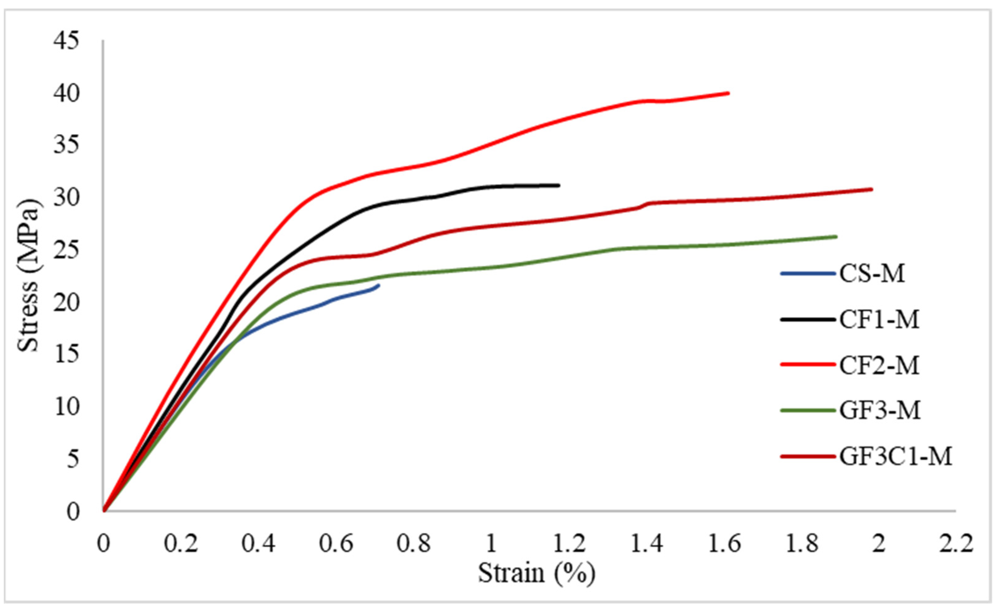
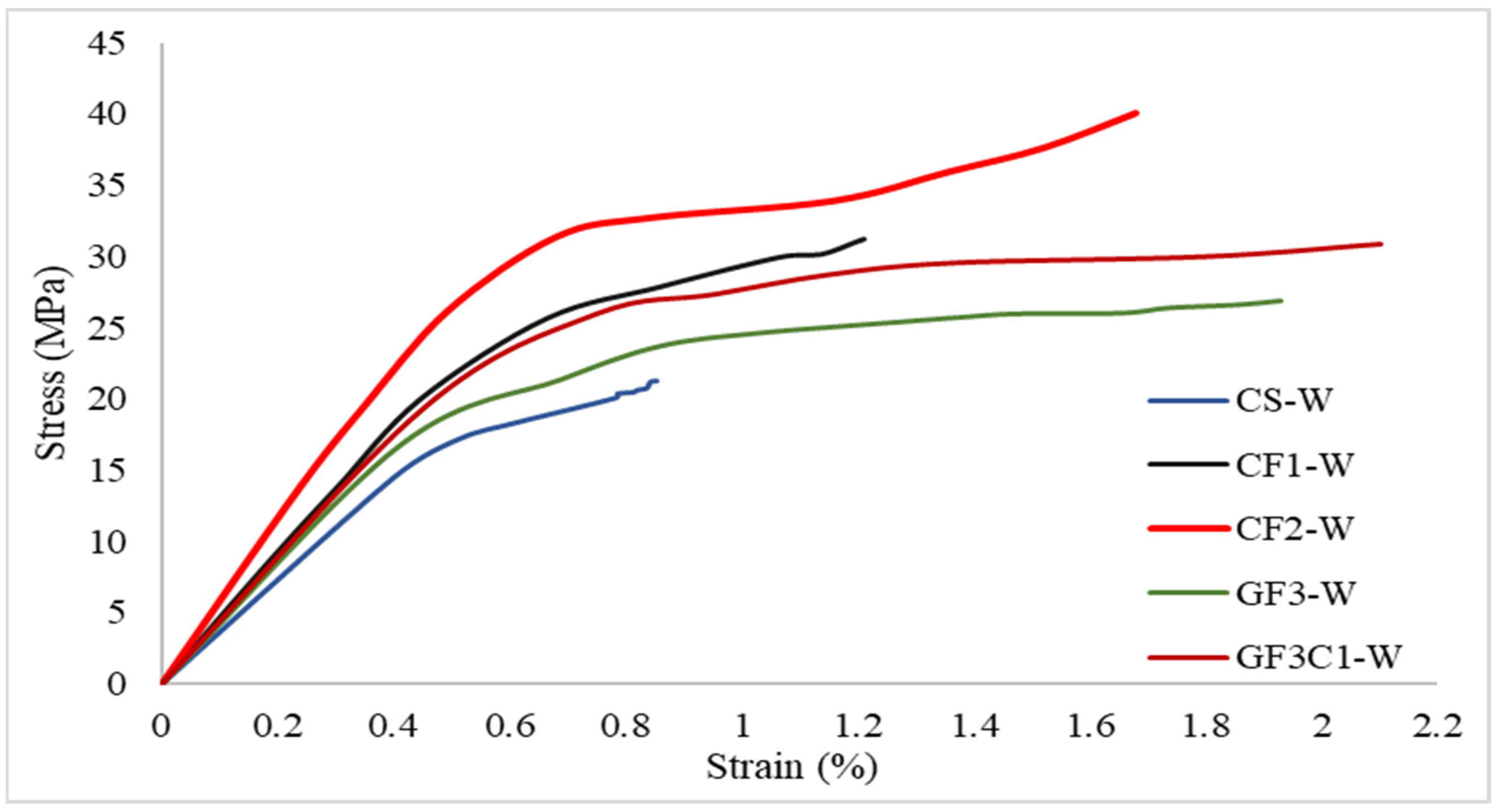
3.5. Effect of Marine and Normal Water

In order to simulate a marine environment, 3.5% by weight of NaCl per liter of water was prepared. Concrete cylinders, both confined and unconfined, were fully immersed in the solution for a duration of four months. Compared to unexposed specimens, the compressive strength of marine water-exposed specimens was slightly lower than that of normal specimens. During the compression loading, at ultimate load, a clicking sound was heard from the cylinder and the failure occurred with a loud noise. Early loading phases caused the FRP fabrics to gradually rupture, which was accompanied by an abrupt, loud noise and a pre-failure cracking noise [54]. FRP fabrics overlapped at the specimen’s intermediate height, where failure began to extend to the top and bottom of the structures. The crack was initially noticed near the end portions of the cylinder, and later moved to the middle section, before failure. The outer layer of FRP showed a longer time to fail and the inner layer tended to rupture first when the load was applied. The failure patterns clearly show that the type and time of exposure had a significant effect on unconfined cylinders and limited effects on confined cylinders. The ultimate compressive load of unconfined specimens was 21.5 MPa, which is slightly less than the ambient condition. Exposure to NaCl had no appreciable effect on the strength of the FRP-confined specimens. The stress–strain response of marine water-exposed specimens is given in Figure 7. The stress–strain behavior of both confined and unconfined specimens had no major impact by exposure to saltwater. Compared to confined specimens, there was a small percentage drop in the compressive stress and strain of unconfined specimens. The presence of NaCl in the water reduced the tensile strength of the fiber and thereby decreased the ultimate strength of the cylinder [23]. The compressive stress of one-layer CFRP specimens was equivalent to three-layer MWCNT incorporated GFRP specimens, but the axial strain of GF3C1-M was 69% and 22% higher than CF1-M and CF2-M, respectively. This percentage increase was due to the combined effect of MWCNT and GFRP systems, which resisted the attack of salty ions present in the water. Test results of specimens exposed to marine and normal water environments are given in Table 7 and Table 8.
In the case of normal water, the concrete cylinders were immersed in normal water conditions for 120 days. The compressive strength and strain of exposed specimens were similar to unexposed specimens. The stress–strain behavior of both confined and unconfined concrete specimens is depicted in Figure 8. The findings demonstrate that, in comparison to unconfined examples, the FRP-confined concrete specimens demonstrated superior resistance to normal water. The maximum compressive strength of GF3C1-W is 45% higher than the control specimen and similar to CF1-W. The axial compressive strain of GF3C1-W was not affected by the exposure to normal water for a period of 4 months. Also, GF3C1-W showed a higher axial strain and considerable plastic deformation before failure, which improved the structure’s ductility [54]. The presence of FRP systems and nanofillers improved the axial compressive strength and ductility of concrete specimens [55].

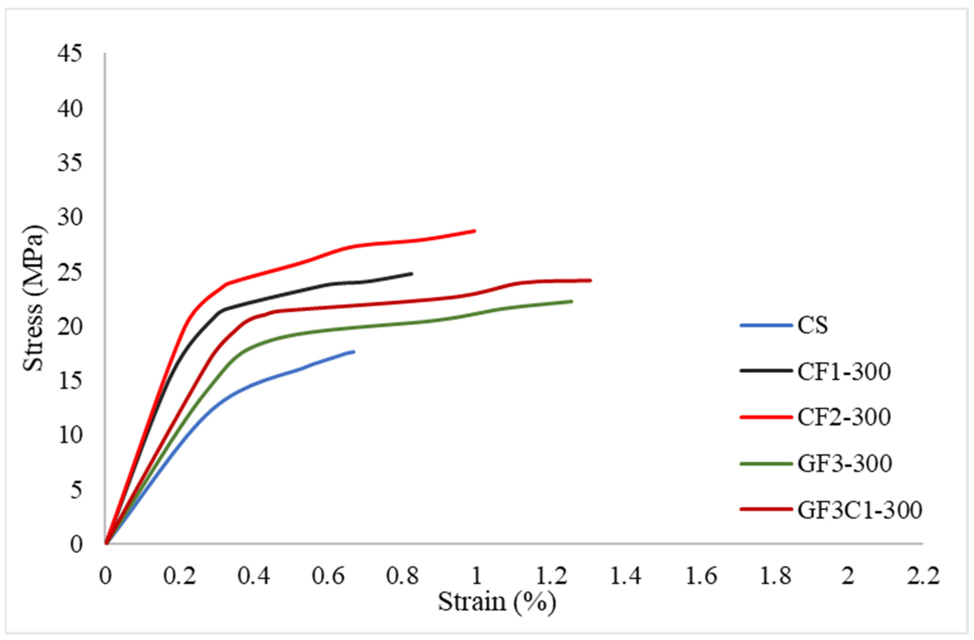
3.6. Elevated Temperature

The properties of FRP-confined concrete cylinders deteriorate when exposed to high temperatures. The specimens were exposed to 100, 200, 300, and 400 °C separately for a period of 2 h. After the exposure, cylinders were allowed to cool at ambient temperature for 1 day and subjected to axial compressive loading. The axial stress and strain were recorded for all specimens. Before the failure, cracking sounds were noticed, which indicated the beginning of stress transfer from concrete to the FRP jacket. In the center portion of the specimen, the concrete core was crushed due to the loading followed by the rupture of the FRP jacket [26]. Several cracks and concrete spalling were observed on the surface of the specimens. Compared to specimens at normal temperatures, the failure mechanism of FRP-confined specimens exposed to high temperatures was more rapid and explosive. Confined and unconfined cylinders subjected to 100 °C and 200 °C did not show any major damage. Compressive stress and axial strain of those specimens were similar to unexposed specimens and did not show any percentage drop in the properties even after the exposure.
The axial compressive strength of specimens exposed to 300 °C is given in Table 9 and the stress–strain pattern is illustrated in Figure 9. Unconfined concrete cylinders after exposure showed a reduction of 21% in compressive strength compared to the ambient condition. Due to the temperature exposure, some microcracks were visible in the surface of the concrete, and during the loading process, existing cracks were propagated vertically to the middle part of the specimen and failed due to crushing. The FRP jacket ruptured in the case of the confined concrete cylinders. When an axial force is applied, a tiny clicking sound is heard due to the lateral expansion of concrete and the activation of the FRP confinement [56].
The failure mode of FRP-wrapped specimens altered as the temperature increased. Failure patterns of specimens exposed to 400 °C are given in Figure 10. Table 10 shows the axial compressive strength of specimens subjected to 400 °C and the stress–strain pattern is presented in Figure 11. Following that, at ultimate compressive force, the FRP jacket broke with an explosive noise, accompanied by concrete crushing and a decrease in applied force. The matrix material was stable at low temperatures. However, at high temperatures, epoxy began to degrade due to its low glass transition temperature, and epoxy-dominated failures were observed at higher temperatures. It was found that the ultimate compressive strength and axial strain of CFRP confinement are enhanced with the number of CFRP layers [1]. When the GFRP confined cylinders were exposed to temperatures of around 300 °C and 400 °C, they lost around 18% and 25% of their initial ultimate strength. The compressive strength of MWCNT integrated GFRP confined cylinders was 27% and 24% greater than exposed unconfined samples, respectively, even after exposure to temperatures of 300 °C to 400 °C [57]. The stress–strain pattern is not significantly affected by temperature exposure. In both curves, the concrete specimens exhibit a linear portion and hardening zone, which is connected by a transition zone [58]. The transition zone of MWCNT incorporated GFRP specimens is longer than CFRP and GFRP confined specimens. At 300 °C, the axial strain of GF3C1-300 is 30% and 38% higher than CF1-300 and CF2-300, respectively. This can be considered as an improvement in the structure’s ductility parameters. In the case of 400 °C, when compared with CF1-400 and CF2-400, the axial strain of GF3C1-400 increased by 50% and 20%, respectively. The incorporation of MWCNT improved the axial strain significantly at elevated temperatures, which may be due to the softened FRP layer or lower confinement pressure offered by the concrete core at higher temperatures. The test results suggest that the characteristics of confined specimens were significantly influenced by the type of FRP system and the quantity of MWCNTs.

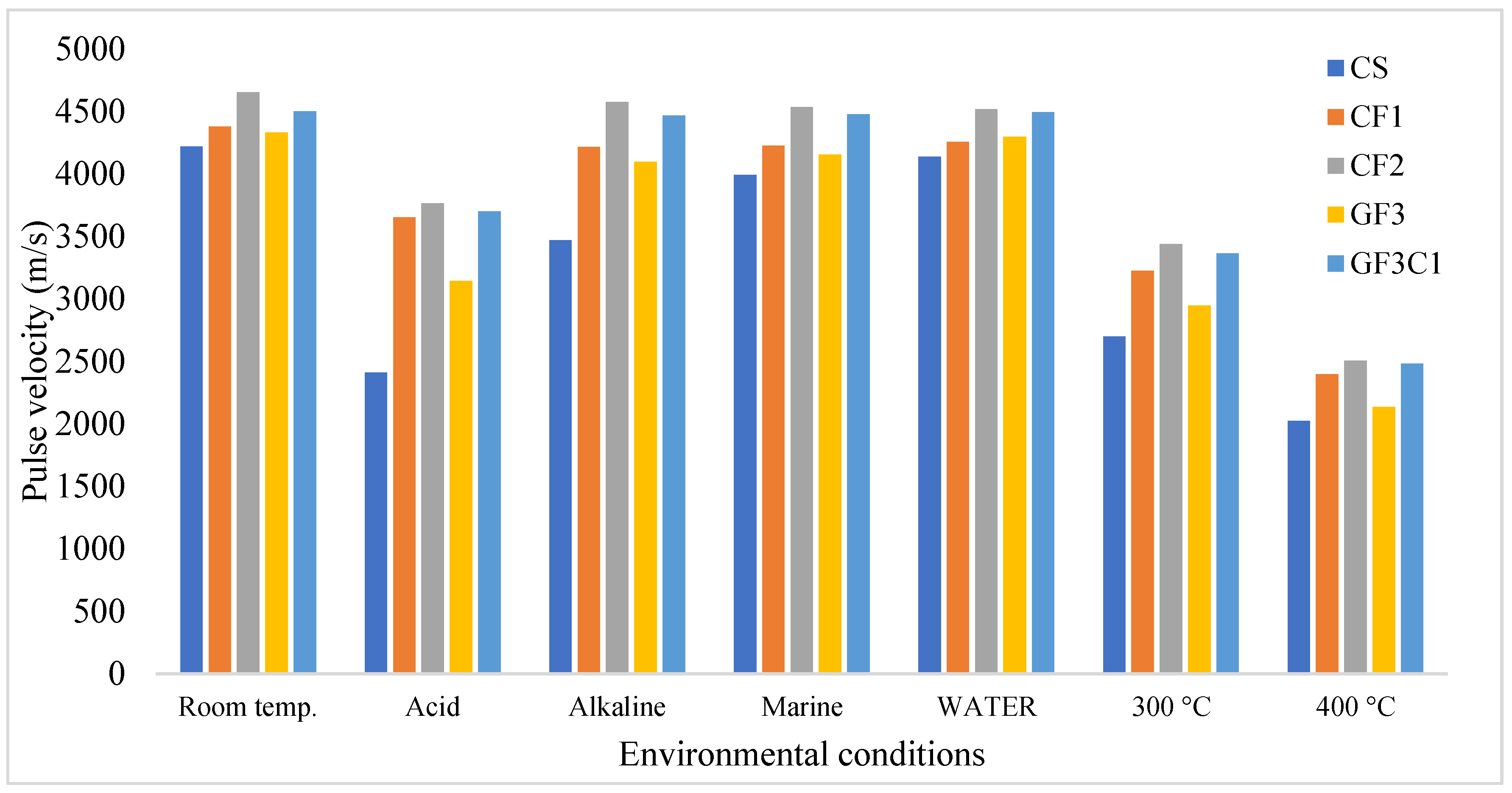
3.7. Ultrasonic Pulse Velocity Test

The ultrasonic pulse velocity test is intended to determine the extent of internal damage in a post-load concrete structural part. UPV testing is utilized to evaluate the confinement effect of various FRP systems on the inner concrete core of specimens. A transmitter and receiver are placed on the upper and bottom sides of the concrete specimens in accordance with IS: 13311-1 (1992) [59], in order to measure the ultrasonic pulse velocity and duration. Ultrasonic pulses are sent into the concrete core by the transmitter, and the receiver, which is positioned on the other side of the specimen, receives the pulses [60]. Concrete’s age, moisture content, and composition significantly affect the pulse velocity. Figure 12 displays the UPV readings of specimens exposed to different environmental conditions and subjected to compressive loading. The velocity ranges between 4000 to 5000 m/s, indicating the better quality of the concrete core. The pulse velocity ranges from 2000 to 2500 m/s, indicating the presence of cracks and faults in the inner core of the concrete. The drop in pulse velocity is determined by the number and width of the internal cracks generated when exposed to a severe environment. Meanwhile, the confinement offered great resistance to the propagation of cracks in the specimens. Under acid exposure, unconfined specimens exhibited a high reduction in pulse velocity, and better pulse velocity was displayed by the confined specimens. Concrete cylinders confined with a one-layer CFRP specimen experienced lower pulse velocity than a three-layer MWCNT incorporated GFRP specimen. The internal resistance of concrete cores to breaking was enhanced by confinement, and the effectiveness of confinement was enhanced by the presence of MWCNTs. The incorporation of MWCNTs helped to form a mechanical interlocking with epoxy chains, which allowed the transmission of stress from low-modulus matrix material to high-modulus reinforcement fabrics. Upon the compression, cracks were formed in the central section of the concrete specimen and when loading continued, the formed crack was transferred to the FRP layers [61,62].

4. Conclusions

The current research focuses on the evaluation and comparison of the strength and durability properties of one and two-layer CFRP, three-layer GFRP, and MWCNT incorporated GFRP confined concrete specimens. The major conclusions drawn are given below:
  • Optimized percentage of MWCNT incorporated GFRP confinement increased the load-carrying capability and thereby the compressive strength of confined cylinders. The axial strain of GF3C1-AC was 75% higher than that of CF1-N and 12% higher than that of CF2-N;
  • When comparing GF3C1-AC and GF3C1-N, the percentage drop in compressive strength of GF3C1-AC was approximately 5%, indicating the resistance offered by MWCNTs. The axial strain of GF3C1-AC was 23% and 12% higher than that of CF1-AC and CF2-AC, respectively. The compressive stress of CF1-AL is almost similar to that of GF3C1-AL and the axial strain of GF3C1-AL was 70% and 30% higher than CF1-AL and CF2-AL, respectively;
  • The compressive stress of one-layer CFRP specimens was equivalent to three-layer MWCNT incorporated GFRP specimens, whereas the axial strain of GF3C1-M was 69% and 22% higher than CF1-M and CF2-M, respectively;
  • The compressive strength of MWCNT integrated GFRP confined cylinders was 27% and 24% greater than exposed unconfined samples, respectively, even after exposure to temperatures of 300 °C to 400 °C. At 300 °C, the axial strain of GF3C1-300 is 30% and 38% higher than CF1-300 and CF2-300, respectively. This can be considered as an improvement in the structure’s ductility parameters. In the case of 400 °C, when compared with CF1-400 and CF2-400, the axial strain of GF3C1-400 increased by 50% and 20%, respectively.
From the above test results, it can be inferred that retrofitting of concrete cylinders can be efficiently carried out using MWCNT incorporated GFRP confined specimens and can be considered as a substitute for costly CFRP systems. This can be used in applications where medium load-bearing capacity is needed, which can resist various chemical attacks and high-temperature exposure.

Author Contributions

Conceptualization, K.J., M.K.M. and S.S.K.; methodology, K.J., M.K.M. and S.S.K.; validation, S.S.K.; formal analysis, K.J., M.K.M., P.K.S. and S.S.K.; investigation, K.J. and M.K.M.; resources, K.J. and M.K.M.; data curation, S.S.K.; writing—original draft preparation, S.S.K.; writing—review and editing, K.J., M.K.M. and P.K.S.; visualization, S.S.K.; project administration, K.J. and M.K.M. All authors have read and agreed to the published version of the manuscript.

Funding

This research received no external funding.

Data Availability Statement

Data are contained within the article.

Acknowledgments

The authors would like to thank the Department of Mechanical Engineering, Amrita School of Engineering, Coimbatore for the tensile tests of the composite laminates.

Conflicts of Interest

The authors declare no conflicts of interest.

References

  1. Akogbe, R.-K.; Liang, M.; Wu, Z.-M. Size Effect of Axial Compressive Strength of CFRP Confined Concrete Cylinders. Int. J. Concr. Struct. Mater. 2011, 5, 49–55. [Google Scholar] [CrossRef]
  2. Issa, M.A.; Alrousan, R.Z.; Issa, M.A. Experimental and Parametric Study of Circular Short Columns Confined with CFRP Composites. J. Compos. Constr. 2009, 13, 135–147. [Google Scholar] [CrossRef]
  3. Padanattil, A.; Karingamanna, J.; Mini, K.M. Novel Hybrid Composites Based on Glass and Sisal Fiber for Retrofitting of Reinforced Concrete Structures. Constr. Build. Mater. 2017, 133, 146–153. [Google Scholar] [CrossRef]
  4. Joseph, L.; Kumar, P.S.; Deeraj, B.D.S.; Joseph, K.; Jayanarayanan, K.; Mini, K.M. Modification of Epoxy Binder with Multi Walled Carbon Nanotubes in Hybrid Fiber Systems Used for Retrofitting of Concrete Structures: Evaluation of Strength Characteristics. Heliyon 2022, 8, e09609. [Google Scholar] [CrossRef] [PubMed]
  5. Sreekumar Kavitha, S.; Joseph, L.; Madhavan, M.K.; Jayanarayanan, K. Comparative Study of Carbon and Glass Fiber Reinforced Polymer Composites for the Confinement of Concrete Columns. Mater. Today Proc. 2023; in press. [Google Scholar] [CrossRef]
  6. Li, D.; Cui, S.; Zhang, J. Experimental Investigation on Reinforcing Effects of Engineered Cementitious Composites (ECC) on Improving Progressive Collapse Performance of Planar Frame Structure. Constr. Build. Mater. 2022, 347, 128510. [Google Scholar] [CrossRef]
  7. Hariharan, H.; Rajeshkumar, G. Investigation of Mechanical Properties of Sisal Fiber and Sugar Palm Fiber Reinforced Hybrid Composites. Qeios 2024, 1–15. [Google Scholar] [CrossRef]
  8. Ramesh, M.; Palanikumar, K.; Reddy, K.H. Mechanical Property Evaluation of Sisal–Jute–Glass Fiber Reinforced Polyester Composites. Compos. Part B Eng. 2013, 48, 1–9. [Google Scholar] [CrossRef]
  9. Sen, T.; Paul, A. Confining Concrete with Sisal and Jute FRP as Alternatives for CFRP and GFRP. Int. J. Sustain. Built Environ. 2015, 4, 248–264. [Google Scholar] [CrossRef]
  10. Chaiyasarn, K.; Hussain, Q.; Joyklad, P.; Rodsin, K. New Hybrid Basalt/E-Glass FRP Jacketing for Enhanced Confinement of Recycled Aggregate Concrete with Clay Brick Aggregate. Case Stud. Constr. Mater. 2021, 14, e00507. [Google Scholar] [CrossRef]
  11. Pan, Y.; Yan, D. Study on the Durability of GFRP Bars and Carbon/Glass Hybrid Fiber Reinforced Polymer (HFRP) Bars Aged in Alkaline Solution. Compos. Struct. 2021, 261, 113285. [Google Scholar] [CrossRef]
  12. Li, W.; Li, W.; Lu, Y.; Hu, B.; Zhou, Y.; Wu, H.; Wang, P.; Ke, L.; Yu, J. Axial Compressive Behavior and Failure Mechanism of CFRP Partially Confined Ultra-High Performance Concrete (UHPC). Constr. Build. Mater. 2024, 426, 136104. [Google Scholar] [CrossRef]
  13. Haj Seiyed Taghia, S.A.; Darvishvand, H.R.; Pourhasan, M. An Economic Approach to the Confinement of Different Concrete Classes with Carbon and Glass Fibers Reinforced Polymers. Int. J. Eng. 2023, 36, 776–787. [Google Scholar] [CrossRef]
  14. Benzaid, R.; Mesbah, H.; Chikh, N.E. FRP-Confined Concrete Cylinders: Axial Compression Experiments and Strength Model. J. Reinf. Plast. Compos. 2010, 29, 2469–2488. [Google Scholar] [CrossRef]
  15. Anand, P.B.; Nagaraja, S.; Jayaram, N.; Sreenivasa, S.P.; Almakayeel, N.; Khan, T.M.Y.; Kumar, R.; Kumar, R.; Ammarullah, M.I. Kenaf Fiber and Hemp Fiber Multi-Walled Carbon Nanotube Filler-Reinforced Epoxy-Based Hybrid Composites for Biomedical Applications: Morphological and Mechanical Characterization. J. Compos. Sci. 2023, 7, 324. [Google Scholar] [CrossRef]
  16. Ghaleb, Z.; Mariatti, M.; Ariff, Z. Synergy Effects of Graphene and Multiwalled Carbon Nanotubes Hybrid System on Properties of Epoxy Nanocomposites. J. Reinf. Plast. Compos. 2017, 36, 685–695. [Google Scholar] [CrossRef]
  17. Zhang, J.; Zhuang, R.; Liu, J.; Mäder, E.; Heinrich, G.; Gao, S. Functional Interphases with Multi-Walled Carbon Nanotubes in Glass Fibre/Epoxy Composites. Carbon 2010, 48, 2273–2281. [Google Scholar] [CrossRef]
  18. Abadel, A.; Abbas, H.; Almusallam, T.; Alshaikh, I.M.H.; Khawaji, M.; Alghamdi, H.; Salah, A.A. Experimental Study of Shear Behavior of CFRP Strengthened Ultra-High-Performance Fiber-Reinforced Concrete Deep Beams. Case Stud. Constr. Mater. 2022, 16, e01103. [Google Scholar] [CrossRef]
  19. Smith, S.T.; Kim, S.J.; Zhang, H. Behavior and Effectiveness of FRP Wrap in the Confinement of Large Concrete Cylinders. J. Compos. Constr. 2010, 14, 573–582. [Google Scholar] [CrossRef]
  20. Wahab, N.; Srinophakun, P.; Hussain, Q.; Chaimahawan, P. Performance of Concrete Confined with a Jute–Polyester Hybrid Fiber Reinforced Polymer Composite: A Novel Strengthening Technique. Fibers 2019, 7, 72. [Google Scholar] [CrossRef]
  21. Zhang, Q.; Wu, J.; Gao, L.; Liu, T.; Zhong, W.; Sui, G.; Zheng, G.; Fang, W.; Yang, X. Dispersion Stability of Functionalized MWCNT in the Epoxy–Amine System and Its Effects on Mechanical and Interfacial Properties of Carbon Fiber Composites. Mater. Des. 2016, 94, 392–402. [Google Scholar] [CrossRef]
  22. Feng, C.; Yu, F.; Fang, Y. Mechanical Behavior of PVC Tube Confined Concrete and PVC-FRP Confined Concrete: A Review. Structures 2021, 31, 613–635. [Google Scholar] [CrossRef]
  23. Li, Y.-L.; Zhao, X.-L.; Raman, R.S. Durability of Seawater and Sea Sand Concrete and Seawater and Sea Sand Concrete–Filled Fibre-Reinforced Polymer/Stainless Steel Tubular Stub Columns. Adv. Struct. Eng. 2021, 24, 1074–1089. [Google Scholar] [CrossRef]
  24. Cleary, D.B.; Cassino, C.D.; Tortorice, R.; Newell, J.A.; Tyers, B.W. Effect of Elevated Temperatures on a Fiber Composite Used to Strengthen Concrete Columns. J. Reinf. Plast. Compos. 2003, 22, 881–895. [Google Scholar] [CrossRef]
  25. Cerniauskas, G.; Tetta, Z.; Bournas, D.A.; Bisby, L.A. Concrete Confinement with TRM versus FRP Jackets at Elevated Temperatures. Mater. Struct. 2020, 53, 58. [Google Scholar] [CrossRef]
  26. Al-Salloum, Y.A.; Elsanadedy, H.M.; Abadel, A.A. Behavior of FRP-Confined Concrete after High Temperature Exposure. Constr. Build. Mater. 2011, 25, 838–850. [Google Scholar] [CrossRef]
  27. Li, Y.; Liu, X.; Wu, M. Mechanical Properties of FRP-Strengthened Concrete at Elevated Temperature. Constr. Build. Mater. 2017, 134, 424–432. [Google Scholar] [CrossRef]
  28. Xiang, Z.; Tong, Y.; Niu, J.; Yin, L.; Zhou, J. Experimental Study on the Axial Compressive Mechanical Performance of Concrete Short Columns Jointly Confined with CC and CFRP after Sulfate Attack. J. Build. Eng. 2024, 95, 110342. [Google Scholar] [CrossRef]
  29. Alzeebaree, R.; Çevik, A.; Mohammedameen, A.; Niş, A.; Gülşan, M.E. Mechanical Performance of FRP-Confined Geopolymer Concrete under Seawater Attack. Adv. Struct. Eng. 2020, 23, 1055–1073. [Google Scholar] [CrossRef]
  30. Zhou, Y.; Li, M.; Sui, L.; Xing, F. Effect of Sulfate Attack on the Stress–Strain Relationship of FRP-Confined Concrete. Constr. Build. Mater. 2016, 110, 235–250. [Google Scholar] [CrossRef]
  31. Alzeebaree, R.; Çevik, A.; Nematollahi, B.; Sanjayan, J.; Mohammedameen, A.; Gülşan, M.E. Mechanical Properties and Durability of Unconfined and Confined Geopolymer Concrete with Fiber Reinforced Polymers Exposed to Sulfuric Acid. Constr. Build. Mater. 2019, 215, 1015–1032. [Google Scholar] [CrossRef]
  32. IS 10262; Guidelines for Concrete Mix Design Proportioning. Indian Standard: New Delhi, India, 2009.
  33. Sarath Kumar, P.; Jayanarayanan, K.; Deeraj, B.D.S.; Joseph, K.; Balachandran, M. Synergistic Effect of Carbon Fabric and Multiwalled Carbon Nanotubes on the Fracture, Wear and Dynamic Load Response of Epoxy-Based Multiscale Composites. Polym. Bull. 2022, 79, 5063–5084. [Google Scholar] [CrossRef]
  34. Ispir, M.; Dalgic, K.D.; Ilki, A. Hybrid Confinement of Concrete through Use of Low and High Rupture Strain FRP. Compos. Part B Eng. 2018, 153, 243–255. [Google Scholar] [CrossRef]
  35. Micelli, F.; Mazzotta, R.; Leone, M.; Aiello, M.A. Review Study on the Durability of FRP-Confined Concrete. J. Compos. Constr. 2015, 19, 04014056. [Google Scholar] [CrossRef]
  36. Kodur, V. Properties of Concrete at Elevated Temperatures. ISRN Civ. Eng. 2014, 2014, 468510. [Google Scholar] [CrossRef]
  37. El-Hacha, R.; Green, M.F.; Wight, G.R. Effect of Severe Environmental Exposures on CFRP Wrapped Concrete Columns. J. Compos. Constr. 2010, 14, 83–93. [Google Scholar] [CrossRef]
  38. Rasana, N.; Jayanarayanan, K. Experimental and Micromechanical Modeling of Fracture Toughness: MWCNT-Reinforced Polypropylene/Glass Fiber Hybrid Composites. J. Thermoplast. Compos. Mater. 2019, 32, 1031–1055. [Google Scholar] [CrossRef]
  39. Tehrani, M.; Boroujeni, A.Y.; Hartman, T.B.; Haugh, T.P.; Case, S.W.; Al-Haik, M.S. Mechanical Characterization and Impact Damage Assessment of a Woven Carbon Fiber Reinforced Carbon Nanotube–Epoxy Composite. Compos. Sci. Technol. 2013, 75, 42–48. [Google Scholar] [CrossRef]
  40. Xue, Y.; Wu, W.; Jacobs, O.; Schädel, B. Tribological Behaviour of UHMWPE/HDPE Blends Reinforced with Multi-Wall Carbon Nanotubes. Polym. Test. 2006, 25, 221–229. [Google Scholar] [CrossRef]
  41. Tiwari, M.; Billing, B.K.; Bedi, H.S.; Agnihotri, P.K. Quantification of Carbon Nanotube Dispersion and Its Correlation with Mechanical and Thermal Properties of Epoxy Nanocomposites. J. Appl. Polym. Sci. 2020, 137, 48879. [Google Scholar] [CrossRef]
  42. D638 Standard Test Method for Tensile Properties of Plastics. Available online: https://www.astm.org/d0638-14.html (accessed on 14 June 2024).
  43. Parameswaranpillai, J.; Gopi, J.A.; Pathak, C.; Rashmi; Dominic, C.D.M.; Ganguly, S.; Radoor, S.; Krishnasamy, S. Mechanical Properties of Epoxy/Carbon Nanotube Composites. In Synthetic and Natural Nanofillers in Polymer Composites; Elsevier: Amsterdam, The Netherlands, 2023; pp. 75–87. ISBN 978-0-443-19053-7. [Google Scholar]
  44. Chandran, A.R.; Radhika, N. Investigation on Mechanical Properties and Wear Behaviour of Chopped Carbon-Basalt Epoxy Hybrid Composite. Mater. Res. Express 2019, 6, 105303. [Google Scholar] [CrossRef]
  45. Sarath Kumar, P.; Jayanarayanan, K.; Balachandran, M. Thermal and Mechanical Behavior of Functionalized MWCNT Reinforced Epoxy Carbon Fabric Composites. Mater. Today Proc. 2020, 24, 1157–1166. [Google Scholar] [CrossRef]
  46. Compressive Strength Test (IS: 4031 (Part 6)—1988). Available online: https://www.scribd.com/document/481271038/Testing-of-CEMENT-2 (accessed on 14 June 2024).
  47. Joseph, L.; Sarath Kumar, P.; Chakravarthi, E.K.; Mogal, A.; Jayanarayanan, K.; Madhavan, M.K. Experimental and Statistical Investigation on Synergistic Effect of Nano Based Epoxy Hybrid FRP on Strength and Durability of Circular Concrete Columns. Dev. Built Environ. 2023, 14, 100163. [Google Scholar] [CrossRef]
  48. Ali Dadvar, S.; Mostofinejad, D.; Bahmani, H. Strengthening of RC Columns by Ultra-High Performance Fiber Reinforced Concrete (UHPFRC) Jacketing. Constr. Build. Mater. 2020, 235, 117485. [Google Scholar] [CrossRef]
  49. Rousakis, T.C. Inherent Seismic Resilience of RC Columns Externally Confined with Nonbonded Composite Ropes. Compos. Part B Eng. 2018, 135, 142–148. [Google Scholar] [CrossRef]
  50. Rousakis, T.C.; Kouravelou, K.B.; Karachalios, T.K. Effects of Carbon Nanotube Enrichment of Epoxy Resins on Hybrid FRP–FR Confinement of Concrete. Compos. Part B Eng. 2014, 57, 210–218. [Google Scholar] [CrossRef]
  51. Pimanmas, A.; Hussain, Q.; Panyasirikhunawut, A.; Rattanapitikon, W. Axial Strength and Deformability of Concrete Confined with Natural Fibre-Reinforced Polymers. Mag. Concr. Res. 2019, 71, 55–70. [Google Scholar] [CrossRef]
  52. Gu, L.; Bennett, T.; Visintin, P. Sulphuric Acid Exposure of Conventional Concrete and Alkali-Activated Concrete: Assessment of Test Methodologies. Constr. Build. Mater. 2019, 197, 681–692. [Google Scholar] [CrossRef]
  53. Arjomandi, A.; Mousavi, R.; Tayebi, M.; Nematzadeh, M.; Gholampour, A.; Aminian, A.; Gencel, O. The Effect of Sulfuric Acid Attack on Mechanical Properties of Steel Fiber-Reinforced Concrete Containing Waste Nylon Aggregates: Experiments and RSM-Based Optimization. J. Build. Eng. 2023, 64, 105500. [Google Scholar] [CrossRef]
  54. Yan, L. Plain Concrete Cylinders and Beams Externally Strengthened with Natural Flax Fabric Reinforced Epoxy Composites. Mater. Struct. 2016, 49, 2083–2095. [Google Scholar] [CrossRef]
  55. Toutanji, H.; Deng, Y. Strength and Durability Performance of Concrete Axially Loaded Members Confined with AFRP Composite Sheets. Compos. Part B Eng. 2002, 33, 255–261. [Google Scholar] [CrossRef]
  56. El-Gamal, S.; Al-Jabri, K.; Al-Mahri, A.; Al-Mahrouqi, S. Effects of Elevated Temperatures on the Compressive Strength Capacity of Concrete Cylinders Confined with FRP Sheets: An Experimental Investigation. Int. J. Polym. Sci. 2015, 2015, 549187. [Google Scholar] [CrossRef]
  57. Pitchan, M.K.; Bhowmik, S.; Balachandran, M.; Abraham, M. Effect of Surface Functionalization on Mechanical Properties and Decomposition Kinetics of High Performance Polyetherimide/MWCNT Nano Composites. Compos. Part A Appl. Sci. Manuf. 2016, 90, 147–160. [Google Scholar] [CrossRef]
  58. Liu, J.; Huo, J.; Wang, H.; Tang, Z.; Zhang, Q.; Yi, S. Experimental Study on Dynamic Mechanical Performance of Post-Fire Concrete Confined by CFRP Sheets. Materials 2024, 17, 2076. [Google Scholar] [CrossRef] [PubMed]
  59. IS 13311-1; Method of Non-Destructive Testing of Concret, Part 1: Ultrasonic Pulse Velocity. Indian Standard: New Delhi, India, 1992.
  60. Mirmiran, A.; Wei, Y. Damage Assessment of FRP-Encased Concrete Using Ultrasonic Pulse Velocity. J. Eng. Mech. 2001, 127, 126–135. [Google Scholar] [CrossRef]
  61. Sasmal, S.; Basu, S.; Himakar, C.V.V.; Kundu, T. Detection of Interface Flaws in Concrete-FRP Composite Structures Using Linear and Nonlinear Ultrasonics Based Techniques. Ultrasonics 2023, 132, 107007. [Google Scholar] [CrossRef]
  62. Rabehi, B.; Ghernouti, Y.; Li, A.; Boumchedda, K. Comparative Behavior under Compression of Concrete Columns Repaired by Fiber Reinforced Polymer (FRP) Jacketing and Ultra High-Performance Fiber Reinforced Concrete (UHPFRC). J. Adhes. Sci. Technol. 2014, 28, 2327–2346. [Google Scholar] [CrossRef]
Figure 1. Schematic illustration of the casting, FRP wrapping, and durability exposure of concrete cylinders.
Jcs 08 00313 g001
Figure 2. TEM images of epoxy–MWCNT composite with (a) 0.5 wt.% (EC0.5), (b) 1 wt.% (EC1), and (c) 1.5 wt.% (EC1.5) MWCNTs.
Jcs 08 00313 g002
Figure 3. Axial compressive stress–strain behavior of different FRP-confined cylinders.
Jcs 08 00313 g003
Figure 4. Failure pattern of concrete specimens exposed to acid exposure: (a) CS-AC; (b) GF3C1-AC.
Jcs 08 00313 g004
Figure 5. Axial compressive stress–strain behavior of FRP-confined cylinders exposed to acid environment.
Jcs 08 00313 g005
Figure 6. Axial compressive stress–strain behavior of FRP-confined cylinders exposed to alkaline environment.
Jcs 08 00313 g006
Figure 7. Axial compressive stress–strain behavior of FRP-confined cylinders exposed to marine environment.
Jcs 08 00313 g007
Figure 8. Axial compressive stress–strain behavior of FRP-confined cylinders exposed to normal water.
Jcs 08 00313 g008
Figure 9. Axial compressive stress–strain behavior of FRP-confined cylinders in elevated temperature (at 300 °C).
Jcs 08 00313 g009
Figure 10. Failure pattern of concrete specimens CS-400 and GF3C1-400 (a) before compression and (b) after compression.
Jcs 08 00313 g010
Figure 11. Axial compressive stress–strain behavior of FRP-confined cylinders in elevated temperature (at 400 °C).
Jcs 08 00313 g011
Figure 12. Ultrasonic pulse velocity of unconfined and confined specimens for different environmental conditions.
Jcs 08 00313 g012
Table 1. Properties of materials used in concrete.
MaterialsProperties
CementSpecific gravity—2.9
Initial setting time—45 min
Final setting time—540 min
Fine aggregate—river sand (Zone II)Specific gravity—2.64
Fineness modulus—2.82
Bulk density—1691 kg/m3
Water absorption—0.8%
Coarse aggregate
(20 mm size)
Specific gravity—2.65
Water absorption—1.8%
Bulk density—1697 kg/m3
Table 2. Specimen nomenclature.
Exposure Environment/Elevated Temp.Composition
Control SpecimenCFRP—1 LayerCFRP—2 LayerGFRP—3 LayerMWCNT Incorporated 3 Layer GFRP
Normal ConditionCS-NCF1-NCF2-NGF3-NGF3C1-N
AcidCS-ACCF1-ACCF2-ACGF3-ACGF3C1-AC
AlkalineCS-ALCF1-ALCF2-ALGF3-ALGF3C1-AL
MarineCS-MCF1-MCF2-MGF3-MGF3C1-M
WaterCS-WCF1-WCF2-WGF3-WGF3C1-W
100 °CCS-100CF1-100CF2-100GF3-100GF3C1-100
200 °CCS-200CF1-200CF2-200GF3-200GF3C1-200
300 °CCS-300CF1-300CF2-300GF3-300GF3C1-300
400 °CCS-400CF1-400CF2-400GF3-400GF3C1-400
Table 3. Tensile characteristics of multiscale and epoxy nanocomposites.
SampleTensile Strength (MPa)Strain at Break (%)Young’s Modulus (GPa)
E 26.7   ± 0.1 2.1   ± 0.3 1.6   ± 0.1
EC0.5 30.8   ± 0.4 2.3   ± 0.3 1.8   ± 0.2
EC1 50.6   ± 0.3 2.4   ± 0.1 4.5   ± 0.4
EC1.5 29.6   ± 0.1 2.2   ± 0.2 2.6   ± 0.1
EC2 29.3   ± 0.2 2.5   ± 0.5 2.3   ± 0.2
ECF1 89.5   ± 0.3 4.5   ± 0.2 6.4   ± 0.1
ECF2 134.4   ± 0.2 6.2   ± 0.3 6.7   ± 0.3
EGF3 71.3   ± 0.5 5.1   ± 0.2 3.1   ± 0.1
EC0.5GF3 76   ± 0.1 5.2   ± 0.1 3.2   ± 0.2
EC1GF3 94.3   ± 0.3 5.3   ± 0.2 4.7   ± 0.1
EC1.5GF3 71.8   ± 0.3 5.2   ± 0.3 3.5   ± 0.1
EC2GF3 65.4   ± 0.1 4.7   ± 0.1 3.8   ± 0.3
Table 4. Axial compressive behavior of FRP-confined cylinders in ambient environment.
Concrete SpecimenCompressive
Strength (f′co or f′cc) (MPa)
Strength
Enhancement (%)
Confinement Effectiveness (f′cc/f′co)Axial Strain (%)
CS-N 22.3   ± 0.4-- 0.9   ± 0.1
CF1-N 31.9   ± 0.2431.43 1.2   ± 0.1
CF2-N 40.2   ± 0.181.31.8 1.7   ± 0.2
GF3-N 27.4   ± 0.3231.22 2   ± 0.1
GF3C1-N 31.7   ± 0.4421.41 2.1   ± 0.4
Table 5. Axial compressive strength of FRP-wrapped cylinders in acid environment.
Concrete
Specimen
Compressive
Strength (f′co or f′cc) (MPa)
Strength
Enhancement (%)
Confinement Effectiveness (f′cc/f′co)Axial Strain
(%)
CS-N 22.3   ± 0.2 - 0.9   ± 0.1
CS-AC 7.1   ± 0.3 - 0.3   ± 0.4
CF1-AC 29.6   ± 0.43171.3 0.9   ± 0.1
CF2-AC 37.8   ± 0.34321.7 1.1   ± 0.2
GF3-AC 21.31   ± 0.22601.1 1.1   ± 0.3
GF3C1-AC 29.9   ± 0.13211.3 1.3   ± 0.2
Table 6. Axial compressive behavior of FRP-wrapped cylinders in alkaline environment.
Concrete SpecimenCompressive
Strength (f′co or f′cc) (MPa)
Strength
Enhancement (%)
Confinement Effectiveness (f′cc/f′co)Axial Strain (%)
CS-N 22.3   ± 0.2-- 0.9   ± 0.1
CS-AL 20.9   ± 0.1-- 0.6   ± 0.2
CF1-AL 30.7   ± 0.2471.4 1.0   ± 0.1
CF2-AL 39.1   ± 0.3871.7 1.3   ± 0.2
GF3-AL 24.7   ± 0.4181.1 1.4   ± 0.1
GF3C1-AL 30.1   ± 0.1441.3 1.7   ± 0.3
Table 7. Axial compressive strength of FRP-wrapped cylinders in marine environment.
Concrete SpecimenCompressive
Strength (f′co or f′cc) (MPa)
Strength Enhancement (%)Confinement Effectiveness (f′cc/f′co)Axial Strain (%)
CS 22.2   ± 0.2-- 0.9   ± 0.1
CS-M 21.3   ± 0.3-- 0.7   ± 0.2
CF1-M 31.1   ± 0.4441.4 1.1   ± 0.3
CF2-M 39.8   ± 0.2851.8 1.6   ± 0.1
GF3-M 26.2   ± 0.1221.2 1.9   ± 0.4
GF3C1-M 30.7   ± 0.2431.4 2   ± 0.2
Table 8. Axial compressive strength of FRP-wrapped cylinders in normal water.
Concrete SpecimenCompressive
Strength (f′co or f′cc) (MPa)
Strength Enhancement (%)Confinement Effectiveness (f′cc/f′co)Axial Strain (%)
CS 22.2   ± 0.2 - 0.9   ± 0.2
CS-W 21.5   ± 0.1 - 0.8   ± 0.4
CF1-W 31.2   ± 0.4461.4 1.2   ± 0.1
CF2-W 40.1   ± 0.5881.8 1.6   ± 0.3
GF3-W 26.8   ± 0.2261.2 1.9   ± 0.2
GF3C1-W 30.9   ± 0.3451.4 2.1   ± 0.1
Table 9. Axial compressive strength of FRP-wrapped cylinders in elevated temperature (at 300 °C).
Concrete SpecimenCompressive
Strength (f′co or f′cc) (MPa)
Strength Enhancement
Compared to CS-300 (%)
Confinement Effectiveness (f′cc/f′co)
Axial Strain (%)
CS 22.3   ± 0.2 - 0.9   ± 0.1
CS-300 17.5   ± 0.1-- 0.6   ± 0.2
CF1-300 24.8   ± 0.3411.4 0.8   ± 0.1
CF2-300 28.6   ± 0.4631.6 0.9   ± 0.3
GF3-300 22.3   ± 0.2271.2 1.2   ± 0.1
GF3C1-300 24.2   ± 0.1381.3 1.3   ± 0.4
Table 10. Axial compressive strength of FRP-wrapped cylinders in elevated temperature (at 400 °C).
Concrete
Specimen
Compressive
Strength (f′co or f′cc) (MPa)
Strength Enhancement
Compared to CS-400 (%)
Confinement Effectiveness (f′cc/f′co)Axial Strain (%)
CS 22.3   ± 0.2-- 0.9   ± 0.1
CS-400 16.4   ± 0.1-- 0.5   ± 0.2
CF1-400 21.8   ± 0.3331.4 0.6   ± 0.1
CF2-400 26   ± 0.4581.6 1   ± 0.3
GF3-400 20.4   ± 0.1241.2 0.9   ± 0.2
GF3C1-400 21.6   ± 0.2311.3 1.2   ± 0.1
Disclaimer/Publisher’s Note: The statements, opinions and data contained in all publications are solely those of the individual author(s) and contributor(s) and not of MDPI and/or the editor(s). MDPI and/or the editor(s) disclaim responsibility for any injury to people or property resulting from any ideas, methods, instructions or products referred to in the content.

