Article

A Comparative Study between a Thermal Spray CoCrFeMnNi0.8V/WC-Co High Entropy Alloy Composite Coating and Plain CoCrFeMnNi0.8V and WC-Co Thermal Spray Coatings

by
Stavros Kiape
1,*,
Maria Glava
1,
Emmanuel Georgatis
1,
Spyros Kamnis
2,3,
Theodore E. Matikas
1 and
Alexandros E. Karantzalis
1
1
Department of Materials Science and Engineering, University of Ioannina, 45110 Ioannina, Greece
2
Computer Science and Biomedical Informatics, University of Thessaly, 35131 Lamia, Greece
3
Castolin Eutectic-Monitor Coatings Ltd., Newcastle upon Tyne NE29 8SE, UK
*
Author to whom correspondence should be addressed.
J. Compos. Sci. 2024, 8(4), 120; https://doi.org/10.3390/jcs8040120
Submission received: 2 February 2024 / Revised: 19 February 2024 / Accepted: 20 March 2024 / Published: 24 March 2024
(This article belongs to the Special Issue Metal Composites, Volume II)

Abstract

:
High entropy alloys (HEAs) have emerged as a frontier in surface engineering, challenging the status quo of traditional alloy systems with their exceptional mechanical properties and corrosion resistance. This study investigates the CoCrFeMnNi0.8V HEA, both as a standalone alloy and in a composite with WC-Co, to evaluate their potential as innovative surface coatings. The CoCrFeMnNi0.8V alloy, enriched with vanadium, demonstrates a unique microstructure with enhanced hardness and wear resistance, while the addition of WC-Co particles contributes to improved toughness and durability. By employing High Velocity Oxy-Fuel (HVOF) thermal spray techniques, coatings are deposited onto steel substrates and subjected to rigorous microstructural characterization, wear, and corrosion resistance testing. The results reveal that the CoCrFeMnNi0.8V coating exhibits impressive corrosion resistance in chloride-rich environments. The composite coating leverages the synergy between the HEA’s inherent corrosion resistance and WC-Co’s wear resistance, striking a balance that suits demanding applications. With optimized processing conditions, the composite WC-Co-reinforced high entropy alloy coating could offer a significant advancement in protective coatings technology, especially for maritime and other corrosive settings. This work not only underscores the versatility of HEAs in surface engineering applications but also opens avenues for the development of new material mixtures.

1. Introduction

1.1. High Entropy Alloys

High entropy alloys (HEAs) represent a transformative approach in material science, challenging conventional alloy design norms. These alloys are notable for their rich compositional diversity, typically comprising five or more principal elements in equiatomic or near-equiatomic ratios. This unique composition results in a high level of configurational entropy, a defining characteristic of HEAs [1,2]. The concept of HEAs deviates from traditional alloy design, which typically revolves around a primary element, enhanced with trace amounts of other elements to modify certain characteristics. In contrast, HEAs’ complex composition often leads to the formation of simple solid solution structures, such as face-centered cubic (FCC), body-centered cubic (BCC), or hexagonal close-packed (HCP) phases. This entropy-driven simplicity in structure is central to the exceptional properties of HEAs, including enhanced strength, superior resistance to wear and corrosion, and remarkable thermal stability, making them suitable for a wide spectrum of applications [3,4].
The genesis of HEAs can be traced back to key studies independently published in 2004, which laid the groundwork for this new class of materials. These studies demonstrated the potential for synthesizing single-phase materials using a multiplicity of principal elements, thereby heralding the advent of HEAs as a new paradigm in materials science [1,2]. Subsequent research on HEAs has significantly expanded, delving into their phase development, microstructure, and properties optimization. HEAs are characterized by a tendency to form solid solution phases, a phenomenon attributed to the high entropy effect. This effect, coupled with the lattice distortion, sluggish diffusion, and cocktail effect—arising from the disparate atomic sizes, melting points, and crystal structures of the constituent elements—endows HEAs with unique structural and dynamic properties [5].
While initial research on HEAs focused on single-phase structures, recent explorations have ventured into the domain of multiphase HEAs. These multiphase alloys provide a synergy of mechanical properties, such as the balance between strength and ductility. The study of multiphase HEAs employs both experimental and theoretical methods, including empirical rules, phase diagram calculations, and cutting-edge machine learning techniques [6]. In particular, machine learning has become a pivotal tool for predicting the phases and properties of HEAs. It can efficiently process complex data sets and has shown promising results in predicting HEAs’ phase and mechanical properties. However, applying machine learning to HEA design also presents challenges, such as the need for comprehensive feature descriptors and the integration of manufacturing process parameters like cooling rates in thermal spray processes [7].
In the context of surface engineering and coatings, HEAs offer innovative solutions, providing alternatives to conventional materials that might be rare, hazardous, or subject to restrictions. Their ability to be tailored to specific applications makes them particularly appealing for surface coating applications, where understanding the impact of rapid solidification and cooling rates is crucial [8].

1.2. The Need for New Alloys in Surface Engineering

Cemented carbides, widely used in surface engineering industrial applications for their hardness and wear resistance, are facing significant challenges that necessitate the exploration of new materials. One of the primary challenges is their cost. The production of cemented carbides often involves expensive raw materials and complex manufacturing processes, leading to high costs [9]. Additionally, the sourcing of these materials is geographically concentrated, making the supply chain vulnerable to geopolitical tensions and market fluctuations. This geographic concentration can lead to supply disruptions, price volatility, and dependence on specific regions for critical materials [10]. Furthermore, cemented carbides are part of a legacy of materials that have been in use for over three decades. While they have served well in numerous applications, the evolving and demanding requirements of modern technology and industry often exceed the capabilities of these traditional materials. This situation limits the application of coatings in new and demanding environments, where improved performance, such as enhanced corrosion resistance, is crucial.
In this context, high entropy alloys (HEAs) emerge as a promising alternative when used alone or in conjunction with cemented carbides in coatings. The primary allure of HEAs lies in their potential to exhibit exceptional hardness, wear resistance, and corrosion resistance, potentially surpassing traditional cemented carbides. One of the significant advantages of HEAs is the flexibility in their composition, which can be tailored from a wide range of elements [11]. This flexibility reduces reliance on specific, expensive, or geopolitically sensitive materials. By diversifying the raw material base, HEAs can offer more stable pricing and supply chains, alleviating the concerns associated with the geographic concentration of raw materials. This aspect is particularly crucial in an era where geopolitical tensions can significantly impact material availability and cost [10].
The diverse compositional possibilities of HEAs also allow for the design of alloys specifically targeted to meet the demands of modern applications. Unlike the traditional cemented carbides, HEAs can be engineered to provide a combination of high hardness, enhanced wear resistance, and superior corrosion resistance, making them suitable for a broader range of applications, including those where environmental factors or extreme conditions are a concern [12]. In the realm of coatings, HEAs offer an opportunity to move beyond the limitations of a 30-year-old legacy. The development of HEAs is not just about creating a new class of materials, it is about addressing the multifaceted challenges faced by industries relying on traditional cemented carbides.

1.3. The Rationale behind This Work

The choice of CoCrFeMnNi0.8V as the primary high entropy alloy (HEA) system for the development of new material mixtures with superior hardness, wear resistance, and corrosion resistance is driven by both machine learning insights, theoretical considerations, and experimental findings [13].
The addition of Vanadium (V) in the CoCrFeMnNi system has been identified through machine learning as a key factor in creating specialized features within the alloy. Machine learning algorithms, capable of analyzing complex material data, have indicated that the incorporation of V at a specific concentration of Nickel (0.8 in this case) significantly enhances certain properties of the alloy. This data-driven approach provides a predictive framework, enabling the identification of optimal compositions that are likely to yield desired material characteristics. Experimentally, the novel microstructure of CoCrFeMnNi0.8V, produced upon casting at a cooling rate of approximately 100 K/s, reveals a unique combination of phases. This includes a dominant globular sigma phase, an FCC matrix, and V-rich particles. This hierarchical microstructure, not previously reported for the CoCrFeMnNiV system, results in a substantial increase in hardness and wear resistance compared to the traditional CoCrFeMnNi. The presence of V-rich particles, promoted by the relatively low Ni content, leads to a higher probability of the V atoms being surrounded by Co, Cr, Fe, and Mn atoms. This phenomenon, coupled with the small particle size and heterogeneous distribution favored by the relatively high cooling rate, contributes to the overall enhanced performance of the alloy in terms of hardness [13,14].
Thermodynamically, the formation of V-rich particles and the overall microstructural evolution in CoCrFeMnNi0.8V are influenced by the heat of mixing of different element pairs. The V-Ni pair, for instance, has a more favorable heat of mixing compared to V-Cr, V-Fe, and V-Mn, suggesting a propensity for these combinations to occur within the alloy system [14].
In the context of corrosion protection, the CoCrFeMnNi0.8V system was chosen due to the synergistic effects of its constituent elements. The presence of Chromium (Cr) in the alloy is particularly significant, as Cr is known for its ability to enhance corrosion resistance. In stainless steels, Chromium is responsible for the formation of a passive, protective oxide layer that guards the metal against corrosion [15]. In the CoCrFeMnNi0.8V system, a similar mechanism can be expected, where Chromium contributes to the formation of a stable and protective passive film on the alloy’s surface. Furthermore, the addition of Vanadium (V) in the CoCrFeMnNi0.8V alloy plays a crucial role in enhancing its corrosion resistance. Vanadium can improve the passivation behavior and stability of the passive film, thereby contributing to the overall corrosion resistance of the alloy [16]. The combination of Vanadium with other elements like Cobalt (Co), Iron (Fe), Manganese (Mn), and Nickel (Ni) in the high entropy context further augments corrosion resistance. This is due to the high entropy effect, which leads to a more homogenized microstructure, potentially resulting in fewer paths for corrosion propagation and a more robust passive layer, especially in challenging environments such as acidic, basic, and chloride-rich conditions [16].
The decision to combine WC-Co (tungsten carbide-cobalt) with the CoCrFeMnNi0.8V high entropy alloy (HEA), is driven by a strategic approach to enhance material properties and overcome certain limitations of WC-Co. WC-Co is renowned for its exceptional hardness and wear resistance, making it a popular choice for cutting tools and wear-resistant applications [17]. However, it has some limitations, particularly in terms of brittleness, corrosion resistance, and the potential for environmental and cost concerns due to its cobalt content [17].
While WC-Co offers high hardness, it can be brittle, which limits its use in applications where impact resistance or structural integrity under stress is crucial [18]. The CoCrFeMnNi0.8V HEA has the potential to offer balanced mechanical properties, including improved toughness, mitigating the brittleness of WC-Co. The HEA’s multi-element composition is expected to lead to a more ductile and resilient microstructure, enhancing the toughness of the composite material. WC-Co’s corrosion resistance can be inadequate in certain environments, limiting its application scope [19]. The CoCrFeMnNi0.8V HEA, with elements like Chromium (Cr) and Vanadium (V), offers superior corrosion resistance [13]. This property is critical in corrosive environments, where WC-Co alone might fail or degrade faster.
In addition, the reliance on cobalt in WC-Co raises concerns regarding cost and supply chain stability, as cobalt is a geopolitically sensitive material [20]. By integrating the CoCrFeMnNi0.8V HEA, the composite material reduces dependence on cobalt, potentially lowering costs and mitigating supply chain risks. The combination of WC-Co with CoCrFeMnNi0.8V allows for the creation of a material with tailored properties. By adjusting the proportions and processing of the composite, it is possible to optimize the material for specific applications, leveraging the hardness and wear resistance of WC-Co and the toughness, ductility, and corrosion resistance of the produced coatings. In summary, while WC-Co alone is a valuable material for certain applications, its combination with specific high entropy alloys is expected to result in a composite material that offers a broader range of properties.
This work aims to explore and establish experimentally how enhanced performance can be achieved, extending application possibilities. This work also aims to address the limitations of using WC-Co alone in key industry sectors that require surface coating protection.

2. Materials and Experimental Methods

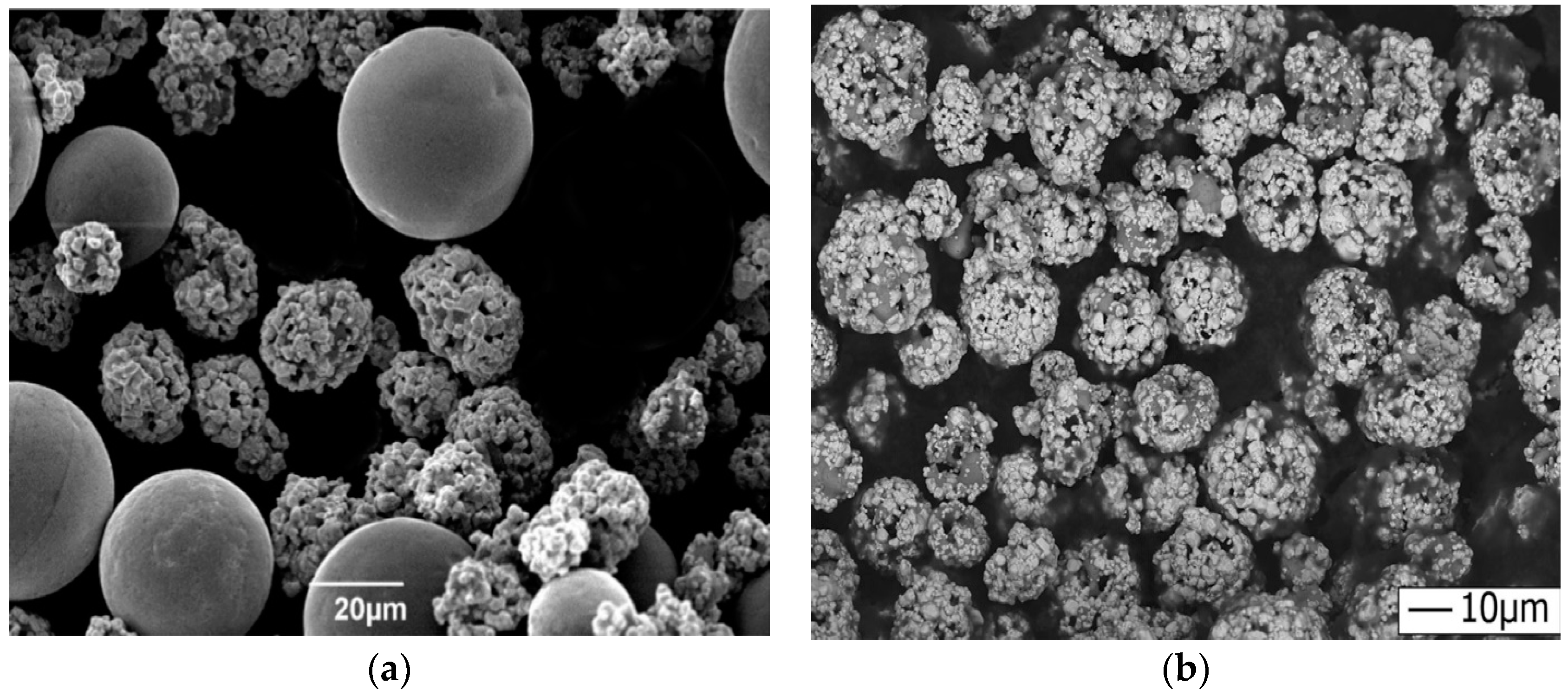
2.1. Feedstock Materials

The CoCrFeMnNi0.8V high entropy alloy (HEA) feedstock material in the form of powder is an R&D product by Castolin Eutectic. It consists of a single BCC solid solution [13]. The powder has an average size of 20–50 µm and is characterized by its lack of porosity and minimal defects. It is produced through gas atomization, a process which typically involves melting the material and then rapidly cooling it with a gas to form fine particles. The chemical composition of the powder is close to the nominal composition of the system but with slightly lower vanadium content and higher chromium content. Elemental mapping (Figure 1) indicates a good distribution of the elements [13]. The powder composition is provided in Table 1.
Scanning Electron Microscope (SEM) images (Figure 2) reveal detailed characteristics of the WC-Co powder feedstock [21]. The particles are predominantly spherical, featuring a surface layered with WC grains, and averaging about 3 μm in size. A characteristic trait of agglomerated and sintered powders is their porous structure. In contrast, the HEA particles, visually larger and greyish in their spherical form compared to WC-Co particles, exhibit non-porous characteristics.

2.2. Deposition Method

Steel substrates (SAE 1070) with dimensions of 160 × 80 × 3 mm3 were subject to a series of coating experiments. Three distinct types of coatings were applied as follows: a solely high entropy alloy (HEA) powder, a solely WC-Co powder, and a mixed composition of 75% HEA and 25% WC-Co by weight. Each coating was uniformly applied to achieve a consistent thickness of 250 µm. Prior to the coating process, the steel substrates underwent thorough preparation. This involved grit-blasting with alumina particles of a 46 µm median size at a distance of 100 mm. This step was followed by a rigorous cleaning process involving high-pressure air blasting and mechanical methods to eliminate any residual grit on the substrate’s surface.
The deposition of the coatings was executed using a patented “compact High Velocity Oxy-Fuel (HVOF)” process [22], characterized by an isentropic plug nozzle. This nozzle accelerates exhaust gases to supersonic speeds, reaching Mach 2.7. The optimization of process parameters for the HVOF gun was previously conducted in-house. This optimization aimed at achieving the best microstructure, indicated by minimal porosity and a binder mean free path, alongside a maximum WC volume percentage and the highest microhardness for the WC-Co coating. The optimization aimed at achieving minimum decarburization by decreasing the flame temperature while maintaining maximum particle impact velocity.

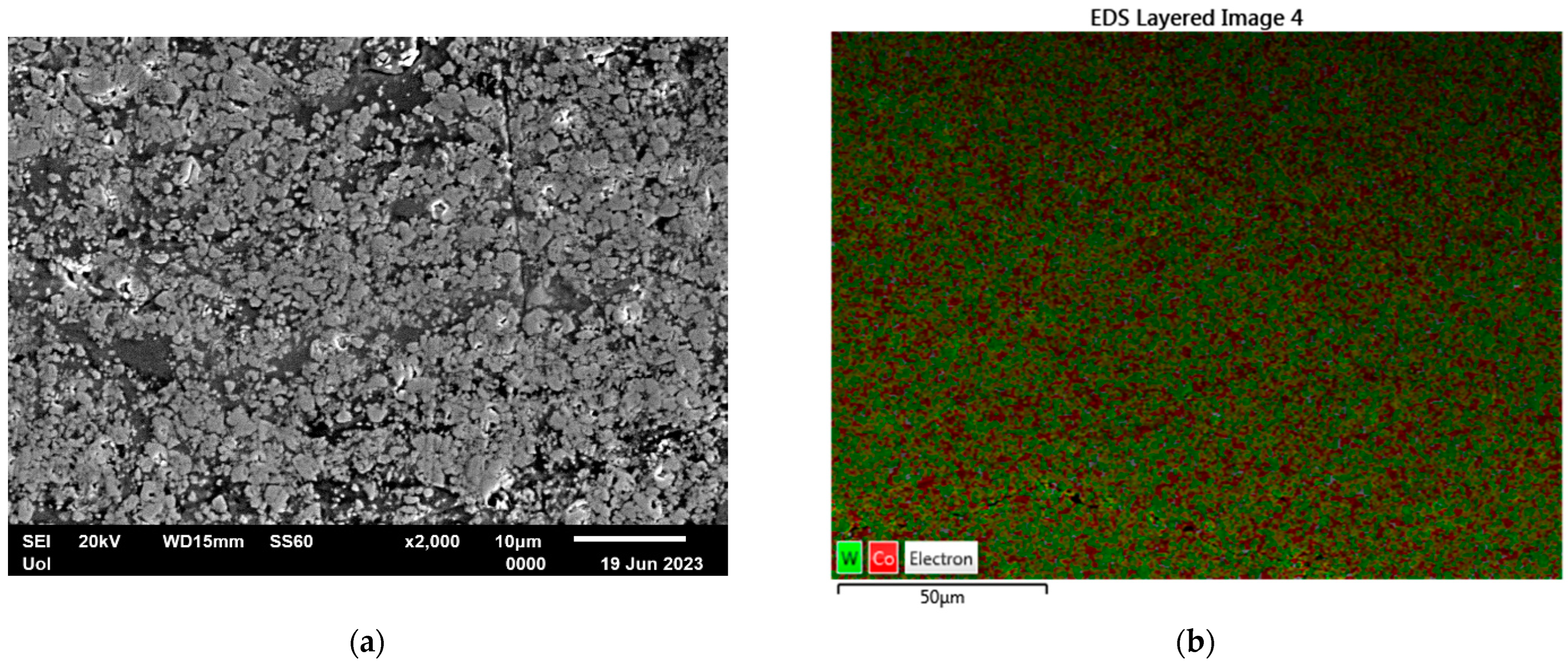
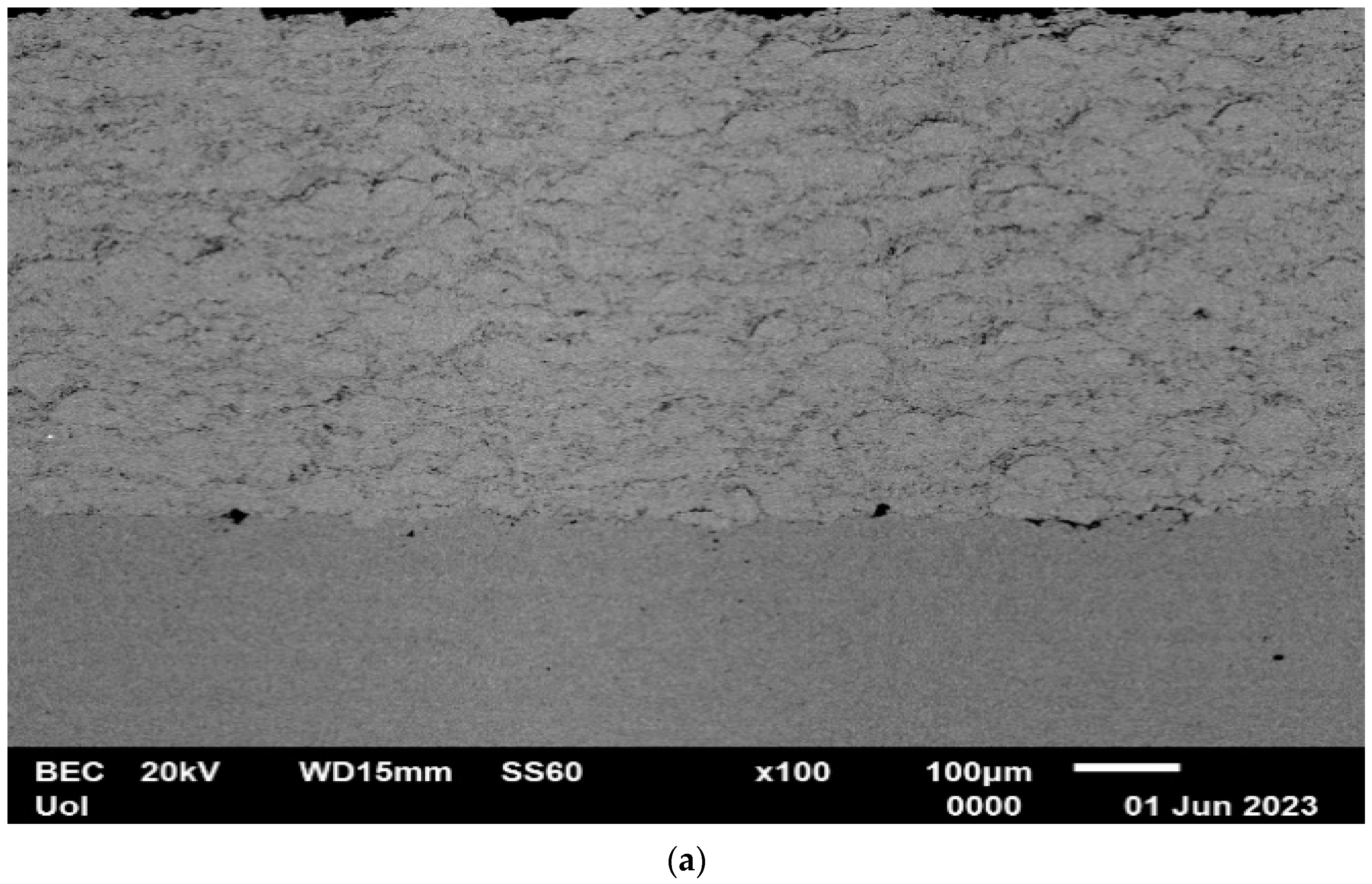
2.3. Scanning Electron Microscopy

Microstructural characterization was conducted using a Scanning Electron Microscope (JEOL 6510 LV, Tokyo, Japan), equipped with backscattered electron (BSE) and energy dispersive spectroscopy (EDS) detectors (both from Oxford Instruments, Abingdon, UK).

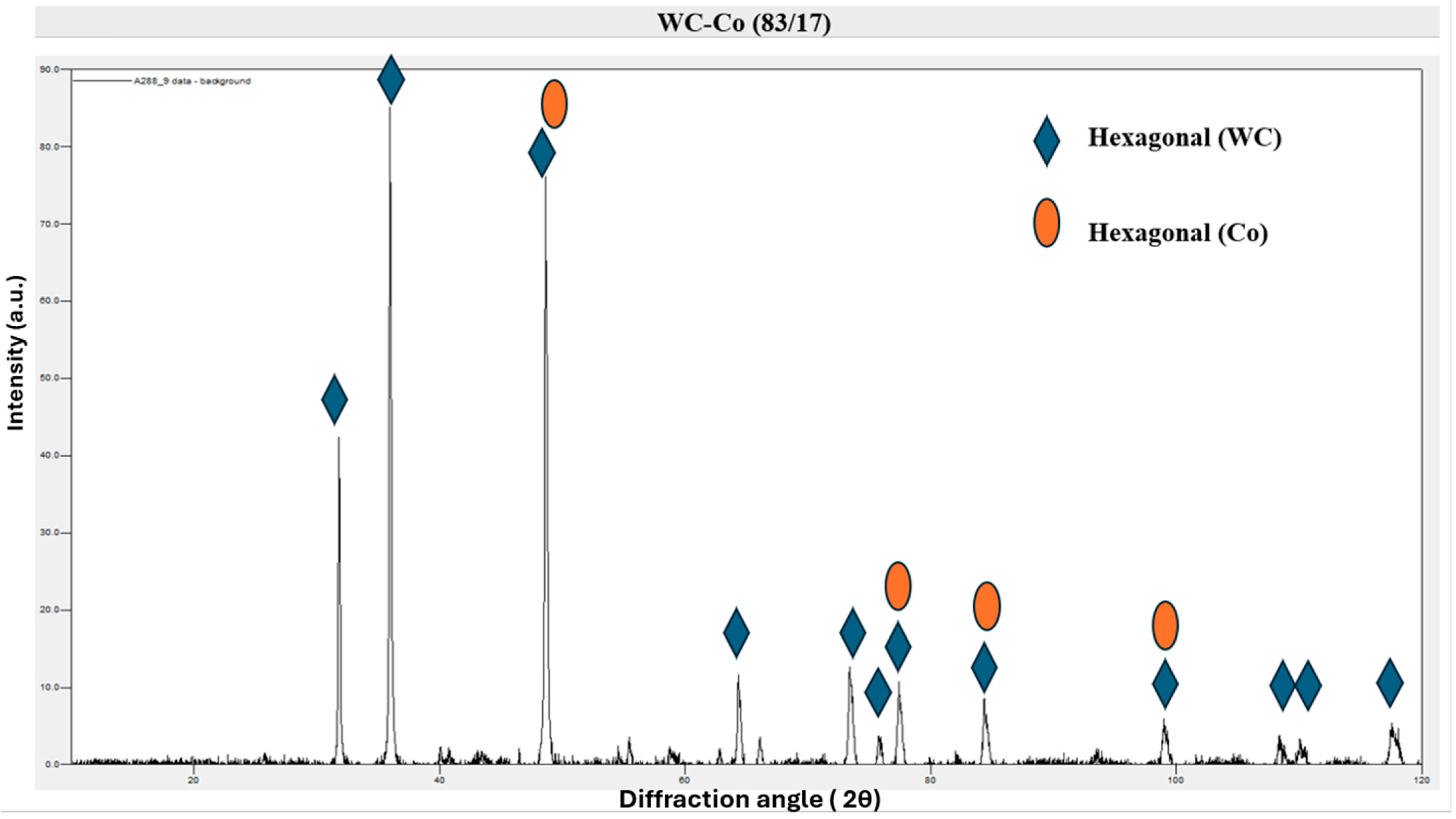
2.4. X-ray Diffraction

Additionally, an X-ray diffraction (XRD) analysis was employed, utilizing a Bruker D8 Advance X-ray diffractometer (Billerica, MA, USA). This analysis involved Cu Kα radiation with a 2θ range of 10–120° at a scanning rate of 0.01°/s.

2.5. Hardness Testing

Hardness tests were carried out with a Universal Hardness Tester (INNOVATEST IN-700), (Innovatest, Maastricht, The Netherlands), featuring a Vickers standard diamond tip. The tests were conducted with a 306 N load. Data for average values and standard deviations were derived from a minimum of ten tests per sample.

2.6. Wear Testing

Wear tests were executed using a CSM Instruments ball-on-disk tribometer (CSM Instruments tribometer, CSM Instruments, Needham, MA, USA). These tests involved a 5 N load and a linear speed of 10 cm/s, using an Al2O3 ball (6 mm diameter) as the counter-body. The total sliding distance was established as 2000 m. Prior to testing, specimens were cleaned with acetone and weighed. Testing was paused every 200 m to re-weigh the specimens and collect possible debris. Each alloy system underwent a minimum of three test runs to ensure reliable data. Finally, the mass loss and wear rate were calculated.

2.7. Corrosion Testing

The corrosion analysis was performed using the cyclic polarization method with a Gamry Reference 600 potentiostat/galvanostat, incorporating a conventional three-electrode cell configuration. In this setup, the test specimen functioned as the working electrode, while a graphite plate served as the counter electrode. For the reference electrode, a saturated calomel electrode (SCE) was utilized. These corrosion tests were conducted in a 3.5 wt.% NaCl solution, emulating the conditions of seawater. To maintain a pH of 7, a buffer solution was added to the water. The samples were immersed in this solution for 1 h to establish the open circuit potential. The polarization scans were then executed at a rate of 10 mV/min.

3. Results and Discussion

3.1. The Microstructure of the WC-Co Coating

In Figure 3a, the darker areas represent the cobalt matrix, which is the binder phase in the WC-Co coating. Cobalt acts as the ductile phase that holds the carbide grains together and provides toughness to the coating. The grey areas are the WC (tungsten carbide) particles, which are the hard phase responsible for the high wear resistance of the coating [23]. WC particles are usually distributed throughout the cobalt matrix and can vary in size and distribution. The porosity of the WC-Co coatings is generally low due to the high peening effect of the impacting particles which suppresses the formation of voids [23]. In Figure 3a, bright patches are visible indicating minor decarburization of WC particles. Decarburization is a process where carbon is lost from the tungsten carbide, leading to the formation of a phase (often W2C or metallic tungsten) that is brighter in electron images due to its different composition and structure. These areas can be more prone to wear due to reduced hardness compared to WC [24]. Despite this minor decarburization, the coating shows a uniform distribution of phases and neighboring WC particles in Figure 3b. This uniform distribution contributes to an increase in microhardness and potentially enhances wear resistance [23].
The presence of WC and Co phases are also verified by the XRD analysis which is presented in Figure 4.

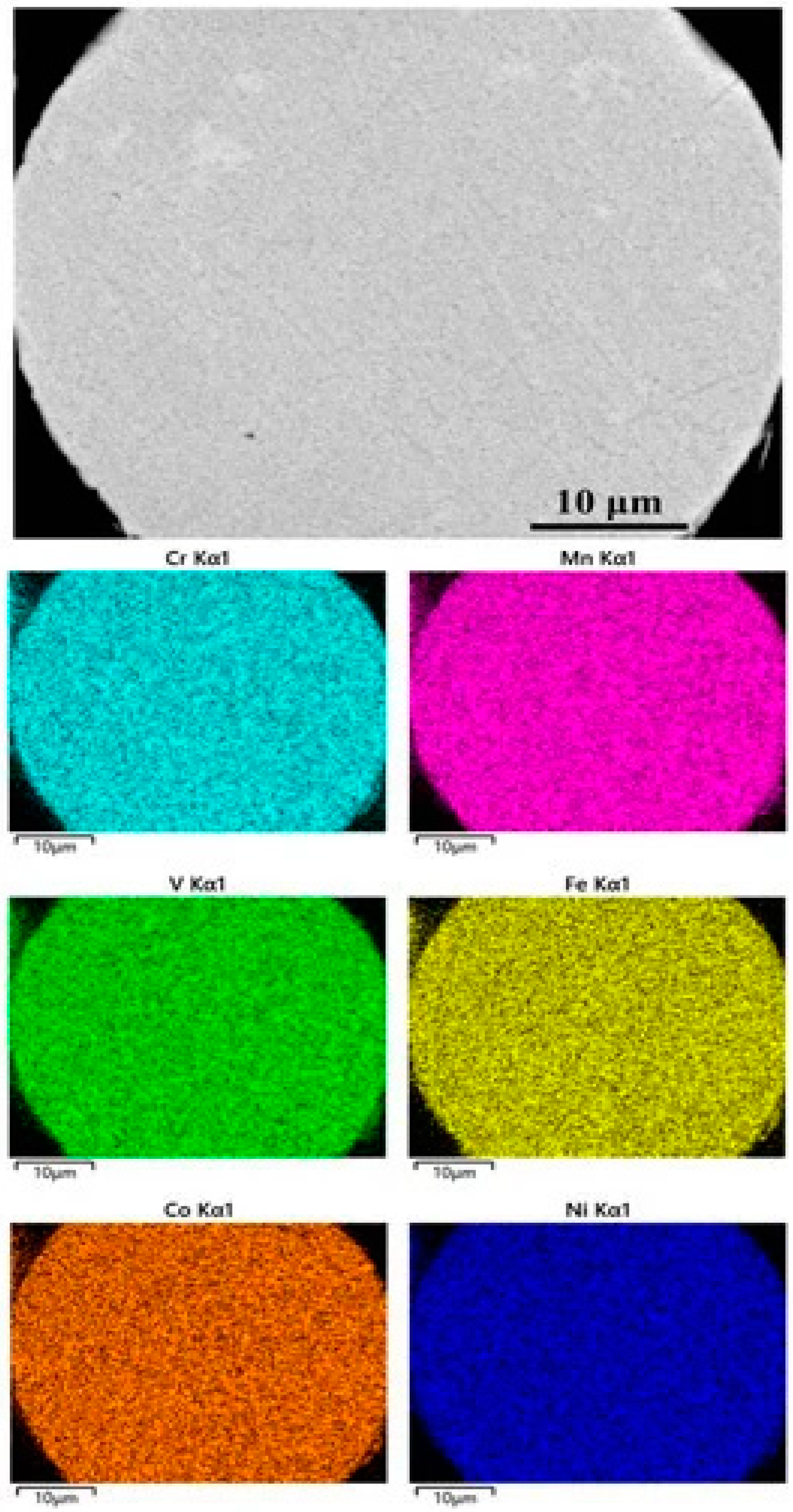
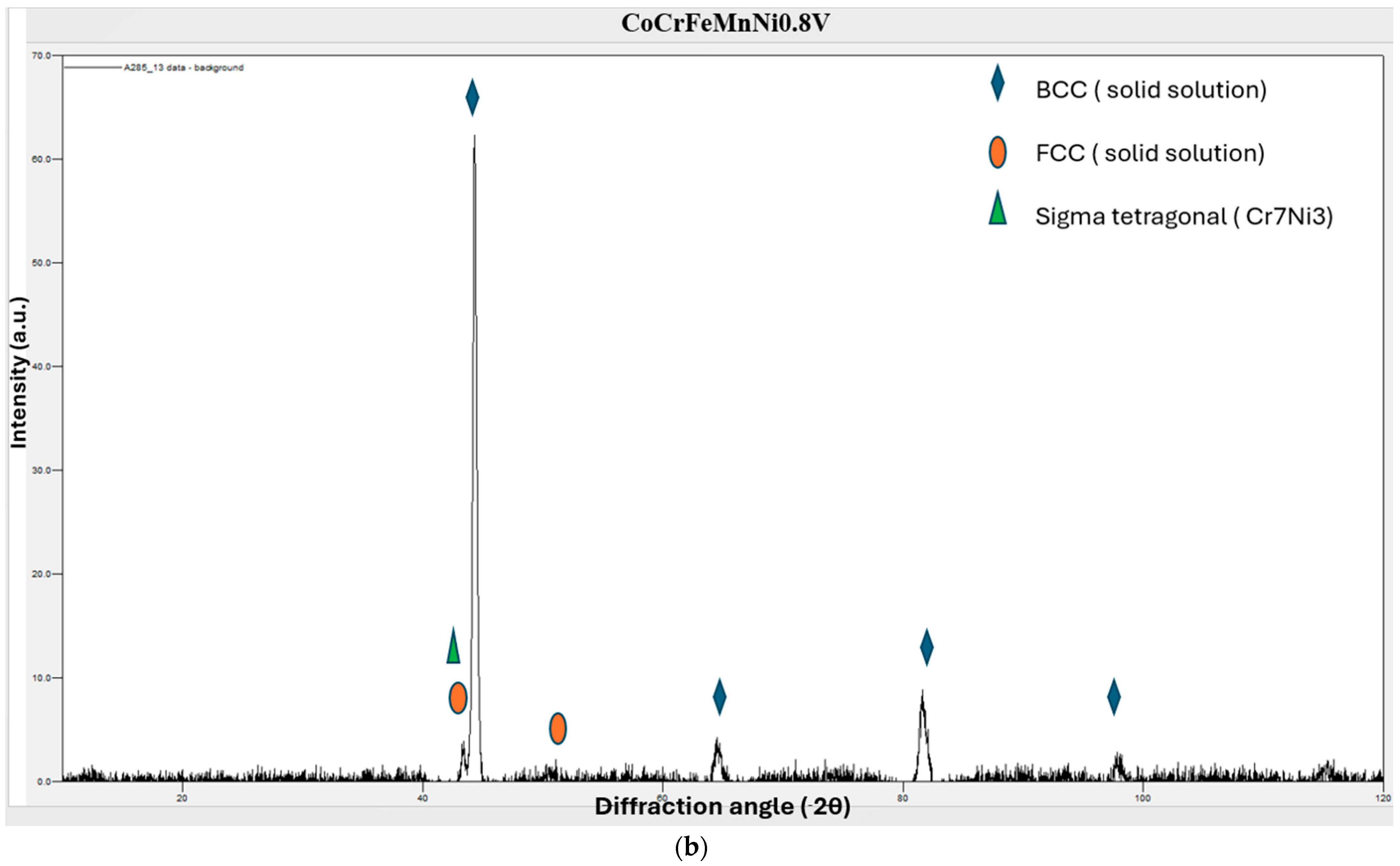
3.2. The Microstructure of the CoCrFeMnNi0.8V HEA Coating

Figure 5a shows a Scanning Electron Microscope (SEM) image of a cross section of the CoCrFeMnNi0.8V coating. The image shows a typical lamellar structure, which is characteristic of coatings applied by thermal spray techniques. The lamellar structure consists of layers or ”splats” formed by the flattening of molten or semi-molten particles as they impact the substrate. This structure suggests that the particles were effectively softened and accelerated by the HVOF process, which led to the formation of thin, overlapping layers upon impact with the substrate. The lamellar structure is beneficial for coating density and mechanical interlocking, contributing to the coating’s overall toughness and integrity [25].
Some oxidation visible at the periphery of the impacted particles can be attributed to the brief exposure of the hot particles to oxygen in the atmosphere during the spraying process. The presence of oxides at the edges of the splats is common in HVOF coatings due to the high temperature of the process [26]. The good deformation of particles seen in the image indicates that the material possesses ductility, allowing the particles to deform plastically upon impact without cracking. This property is essential for the formation of a dense coating, as ductile particles can flatten and spread out, creating a cohesive layer with good mechanical interlocking between the splats [27].
The image shows very few voids or gaps, indicating low porosity within the coating. Low porosity is a desirable attribute because it generally correlates with higher coating density, better wear resistance, and lower permeability to corrosive agents or gases. The uniform interface between the coating and the substrate with no apparent delamination or large voids suggests good adhesion. This is likely a result of the high kinetic energy of the impacting particles during the HVOF process, which promotes mechanical bonding to the substrate [28].
The observation of additional phases in Figure 5b in the coating compared to the feedstock, which has a pure BCC structure, can be attributed to the thermal spray process used in the coating application. During this process, the feedstock material is rapidly heated and then cooled as it is deposited onto a substrate. This rapid heating and cooling can lead to differences in phase composition between the coating and the original feedstock. The thermal history during the spray process can result in the formation of new phases, which are not present in the feedstock material. More specifically, large particles are not fully molten during spray, allowing for the maintenance of the original feedstock crystal structure. Smaller particles may completely melt inflight and resolidify on the substrate. A slower cooling rate may result in the formation of FCC structures or even intermetallic secondary phases [13].

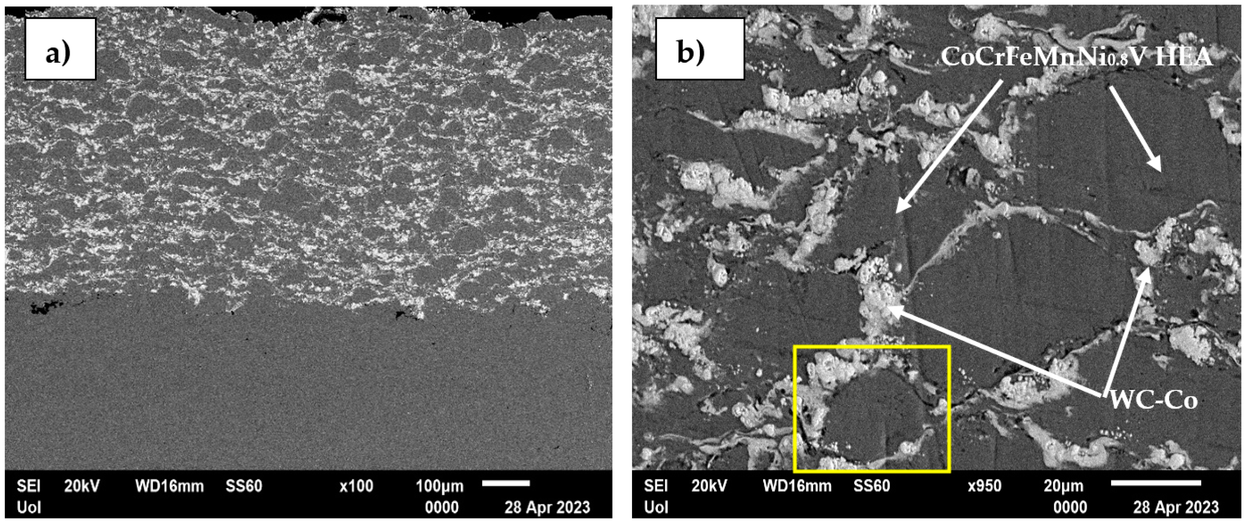
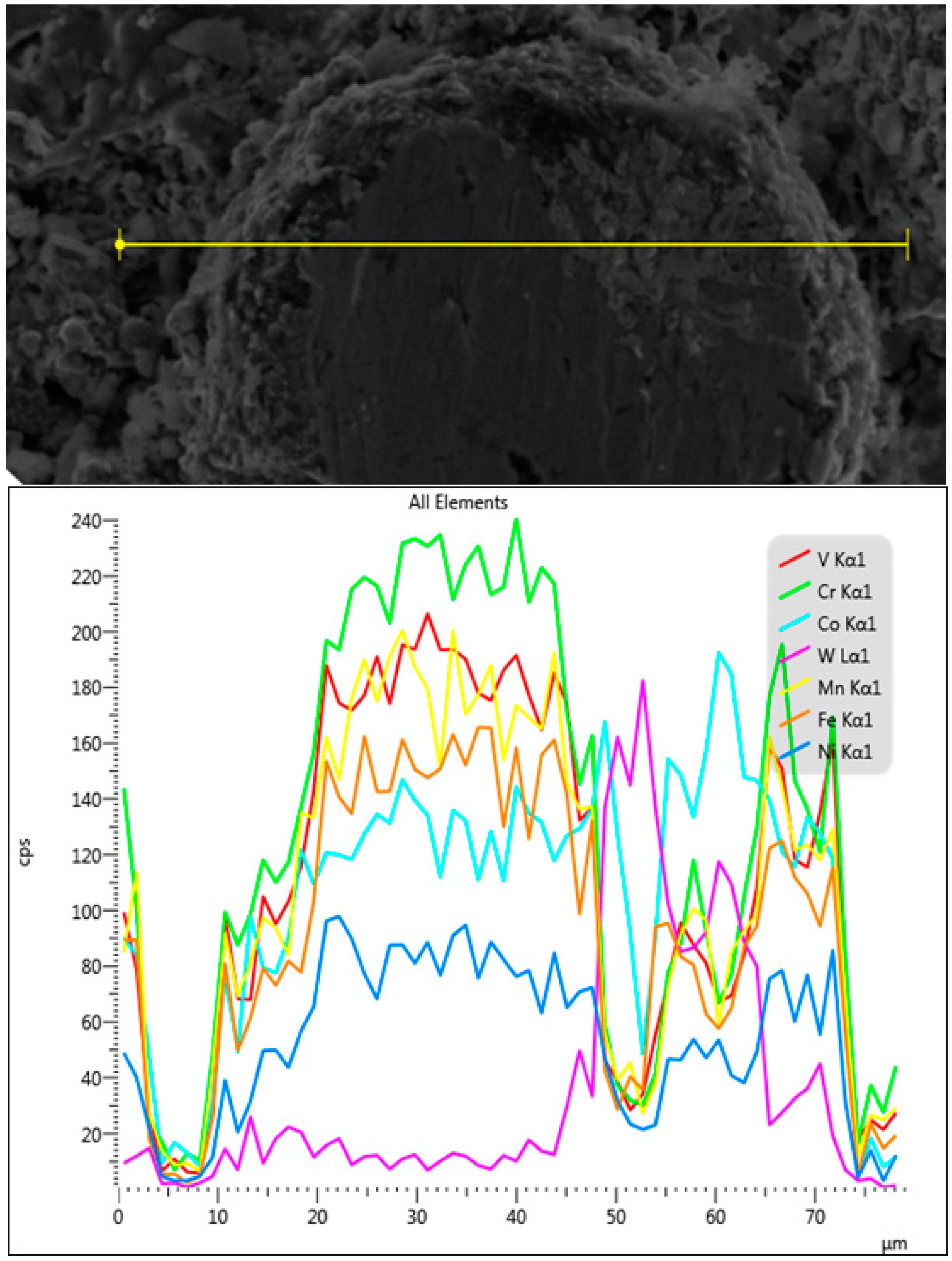
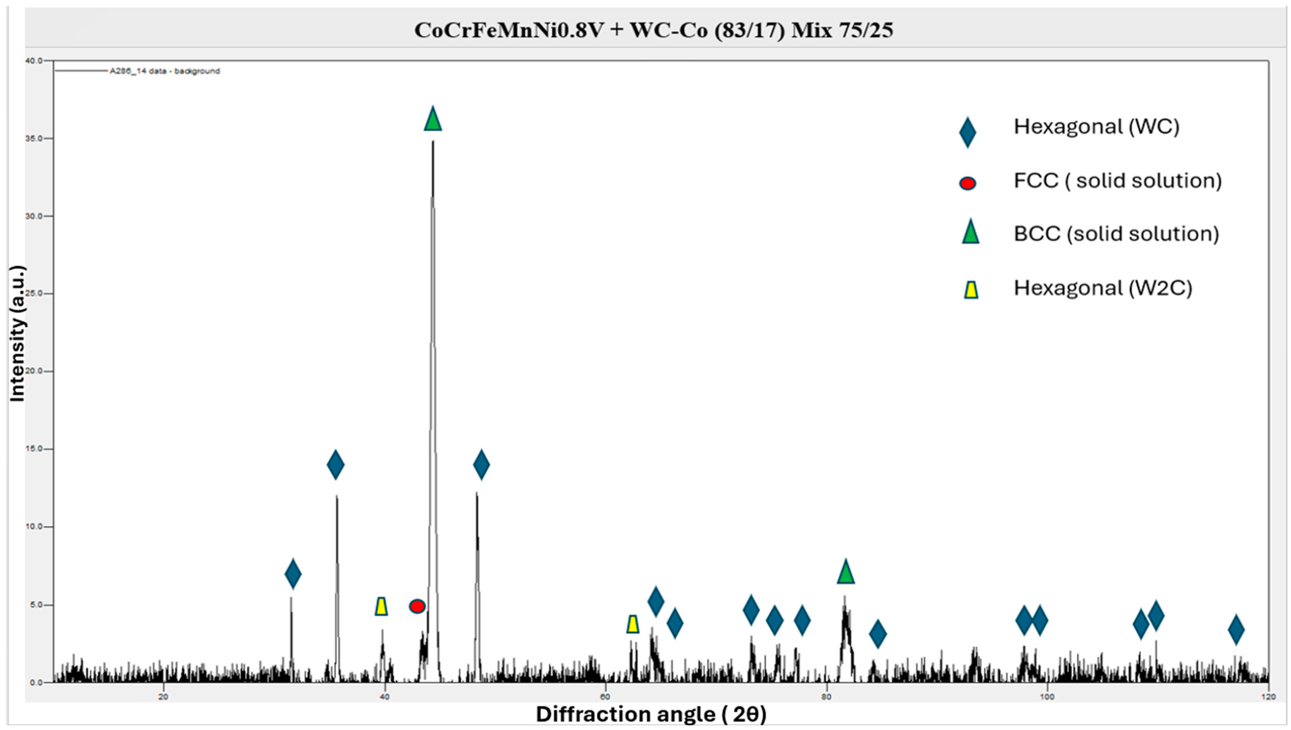
3.3. The Microstructure of the Composite Coating

Figure 6a,b unveil that the coatings possess densely packed structures without any visible cracks, indicating strong adhesion to the substrate. This lack of cracking or delamination at the interface is a clear testament to the coatings’ structural integrity. The measured thickness of the composite coating is within the range of 500–550 μm. Within the microstructure of the coating, the presence of splats from the HEA alloy and WC-Co particles is noticeable. Intriguingly, many of the HEA alloy splats maintain their spherical shape. The average diameter of these spherical HEA alloy splats, based on the measurement of 10 such splats from cross-sectional BSE images, is found to be roughly 40 to 50 μm. It’s important to note that these measurements could vary depending on the sample preparation process.
In addition, the coatings exhibit thin, string-like phases with a bright contrast, evident throughout the microstructure. An Energy Dispersive X-ray (EDX) line scan conducted across one of these sites provided further insights and is presented in Figure 7. The darker contrast areas in the scan (Figure 6b and Figure 7) show high concentrations of HEA and relatively low amounts of W and Co. Interestingly, even the brighter contrast regions still contain measurable quantities of HEA, with a central point showing approximately 15% CoCrFeMnNi0.8V. This suggests some level of mixing between the two distinct powder types used in the coatings, although the exact nature of this mixing, whether due to the EDX generation region being larger than the measured phase or some other reason, remains uncertain. What is also important to mention is the fact that, as Figure 6b and Figure 7 depict, it seems that the cermet phase forms a type of cell that engulfs the HEA phase. If we take into consideration the strong refractory character of the cermet phase, especially due to its WC content, it is logical to assume that this cell may comprise a potential thermal barrier which inhibits heat transfer towards the HEA particles and, as such, they remain partially unmolten, preserving, thus, their initial spherical shape.
X-ray Diffraction (XRD) diffractograms of the sprayed coatings were analyzed as shown in Figure 8. The WC peaks as expected imply a well-formed WC phase. The presence of both FCC and BCC phases indicates a complex solidification history and phase stability influenced by the cooling rate. The presence of decarburized phases in the alloy are indicated by the yellow peak, and the other minor peaks being present possibly indicate the formation of amorphous or nanocrystalline phases during the spray process. These minor, nevertheless, peaks attributed to minor phases contained within the HEA alloy can be seen to have reduced in intensity in the sprayed coating in comparison to the powder feedstock; likely these crystalline phases that were not detected in the powder formed a solid solution during the spray process and had insufficient time to fully recrystallize when the particle was quenched on impact with the substrate.

3.4. Sliding Wear Response

3.4.1. WC-Co Coating

Figure 9a–c show the Scanning Electron Microscope (SEM) image of a worn surface from a WC-Co coating. The image shows a relatively rough surface texture with grooves and scratches, which are indicative of abrasive wear [29]. This wear could be caused by hard particles sliding or rolling over the coating, removing material primarily from the softer cobalt matrix between the harder WC particles.
The EDS analysis (Figure 9c) provides insight into the elemental distribution within the wear track. The presence of elements like aluminum and calcium, which are not inherent to the WC-Co system, suggests the involvement of external materials in the wear process. Aluminum could indicate either material transfer from a counterpart or the presence of third-body particles contributing to abrasive wear. Calcium could be indicative of environmental contamination or a byproduct of chemical reactions during wear, which could be indicative of tribochemical wear.
The lower magnification SEM image (Figure 9a) shows a broad view of the wear track, where areas of contrast are observed likely corresponding to different wear phases or debris embedded in the wear track. The wear appears to be non-uniform, which might suggest that different regions have undergone different wear intensities or mechanisms. The presence of lighter areas typically corresponding to harder WC particles suggests that these areas resisted wear, while the darker matrix (cobalt) has been worn away, pointing to abrasive wear as a key mechanism. At a higher magnification, the SEM image reveals the fine details of the wear track. Visible cracks within the cobalt matrix suggest fatigue wear from cyclic stresses [30].

3.4.2. CoCrFeMnNi0.8V Coating

Figure 10a–c present the SEM images of the wear track at different magnifications along with the correspondent EDS chemical mapping analysis. The SEM image at a lower magnification (Figure 10a) shows a wear track that appears relatively uniform, with no distinct features such as grooves or scratches that would indicate a specific wear mechanism like abrasive wear. The homogeneity of the wear could suggest adhesive wear [31]. The SEM image at a higher magnification (Figure 10b) shows a more granular surface, with contrasts that suggest the presence of different phases or materials. The light areas could be oxidized material that resisted wear, while the darker regions indicate where the material was removed more significantly. The microstructure seems relatively intact without signs of severe deformation, which might suggest that while wear has occurred, the coating has retained some of its integrity. The EDS analysis (Figure 10c) provides information on the elemental composition of the wear track. The distribution of elements such as cobalt (Co), iron (Fe), manganese (Mn), chromium (Cr), and vanadium (V) is relatively uniform. This could suggest that the wear mechanism has affected the entire material evenly, which is more characteristic of oxidative or uniform wear rather than localized wear like localized delamination or abrasion.
In conclusion, the wear of the CoCrFeMnNi0.8V coating seems to be characterized by the relatively uniform removal of material without distinct wear features such as deep grooves or scratches. The EDS data do not indicate selective removal, which could mean the wear mechanism is not significantly influenced by chemical composition differences within the coating. The images do not show significant cracking or delamination, which might suggest that fatigue wear is not the dominant wear mechanism in this case.

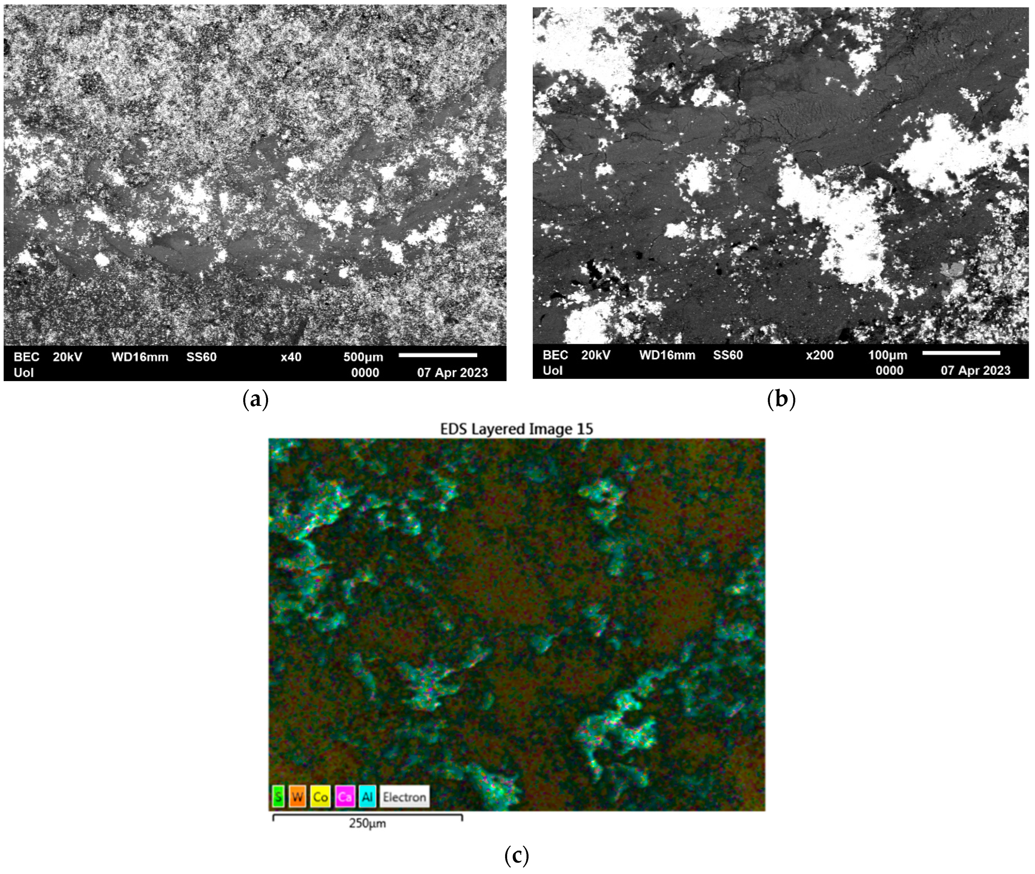
3.4.3. CoCrFeMnNi0.8V/WC-Co Composite Coating

Figure 11a–c present SEM images of the wear track at different magnifications and the related EDS chemical mapping analysis, the data of which are included within the embedded table. In Figure 11a, the SEM image shows a broad area of the coating surface. The variation in grayscale intensity suggests the presence of different phases or materials with varying electron densities. The darker areas could be regions of the CoCrFeMnNi0.8V matrix that have experienced wear, while the lighter spots may indicate the presence of WC particles which are more resistant to wear. The higher magnification image provides a closer look at the surface topography and the wear patterns. The darker regions indicate significant material removal, which could be a result of abrasive or adhesive wear. The presence of pores and craters suggests that particles have been dislodged from the matrix, which can occur in both abrasive and fatigue wear mechanisms. The EDS analysis overlays the elemental distribution onto the SEM image, highlighting where specific elements are concentrated. The distribution of elements such as Co, Fe, Mn, Cr, and Ni is relatively uniform. However, the presence of oxygen suggests some degree of oxidation, which can occur due to high-temperature exposure or corrosive wear. The elemental weight percentages provide quantitative information on the composition of the worn surface. The relatively high weight percentage of tungsten (W) suggests that the WC particles are still present and likely contribute to the wear resistance of the coating. The presence of oxygen indicates that some oxidation has occurred, which could be related to wear or environmental exposure. The presence of aluminum (Al) might be from an external source or material transfer from the counter body during wear testing.
In conclusion, as far as the wear response of the different coatings is concerned, the images and data suggest that the wear mechanism of the produced coating systems involves the following:
  • Abrasive wear: The removal of material and the presence of WC particles suggest that abrasive wear is occurring, with WC particles providing wear resistance [29].
  • Adhesive wear: The smooth wear patterns and potential material transfer indicated by aluminum’s presence may suggest adhesive wear [31].
  • Oxidative wear: The presence of oxygen suggests that oxidative wear may also be a contributing factor, potentially weakening the matrix and leading to increased wear.
  • Fatigue wear: The presence of pores and craters could be indicative of material fatigue and subsequent removal, especially under cyclic loading conditions [30].
The data provided in Table 2 outline the average specific wear rate for different coating materials and indicate the dominant wear mechanism for each. The WC-Co (83-17) coating has the lowest average specific wear rate of 0.8 × 10⁻⁷ g/Nm, which is indicative of high wear resistance. The wear mechanism identified is a combination of abrasive and fatigue wear. The hard WC particles in the coating provide resistance to abrasive wear, and the cobalt matrix can undergo cyclic stress leading to fatigue [32]. The SEM images of this material would likely show WC particles protruding from the cobalt matrix with some areas of cobalt depletion and possibly micro-cracking indicative of fatigue.
The CoCrFeMnNi0.8V coating without WC-Co reinforcement has a significantly higher average specific wear rate of 7.13 × 10⁻⁷ g/Nm. The results imply that there is no single dominant wear mechanism but rather a combination of different mechanisms. This could include abrasive, adhesive, oxidative, and fatigue wear mechanisms. The composite coating material, which combines the CoCrFeMnNi0.8V HEA with WC-Co, has an average specific wear rate of 1.97 × 10⁻⁷ g/Nm. The wear rate is higher than that of pure WC-Co but is significantly lower than the HEA alone, indicating that the addition of WC-Co improves the wear resistance of the HEA. The combined wear mechanism suggests composite benefits from the hardness and abrasion resistance of the WC particles, as well as the toughness and potential for energy dissipation from the HEA matrix, resulting in a wear profile that is a mix of the individual properties of the constituent materials.
The addition of WC-Co to the CoCrFeMnNi0.8V HEA reduces the wear rate considerably compared to the HEA alone. This is likely due to the WC particles in the composite providing increased resistance to abrasive wear, while the HEA matrix contributes to overall toughness and possibly to better resistance to fatigue wear [32]. The combination of materials in the composite aims to utilize the strengths of each constituent: the hardness of WC and the toughness and complex alloying benefits of the HEA.

3.5. Corrosion Resistance

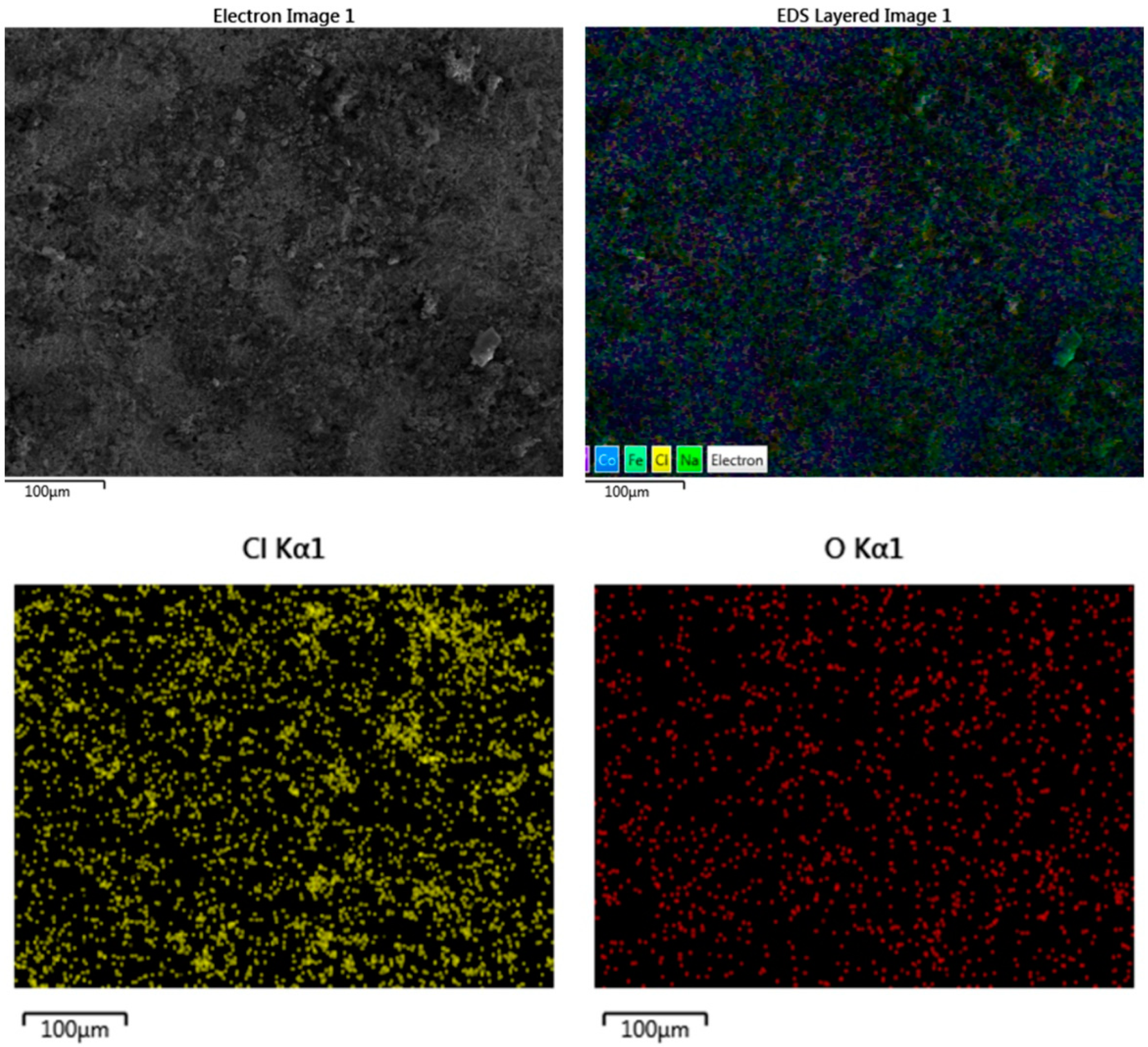
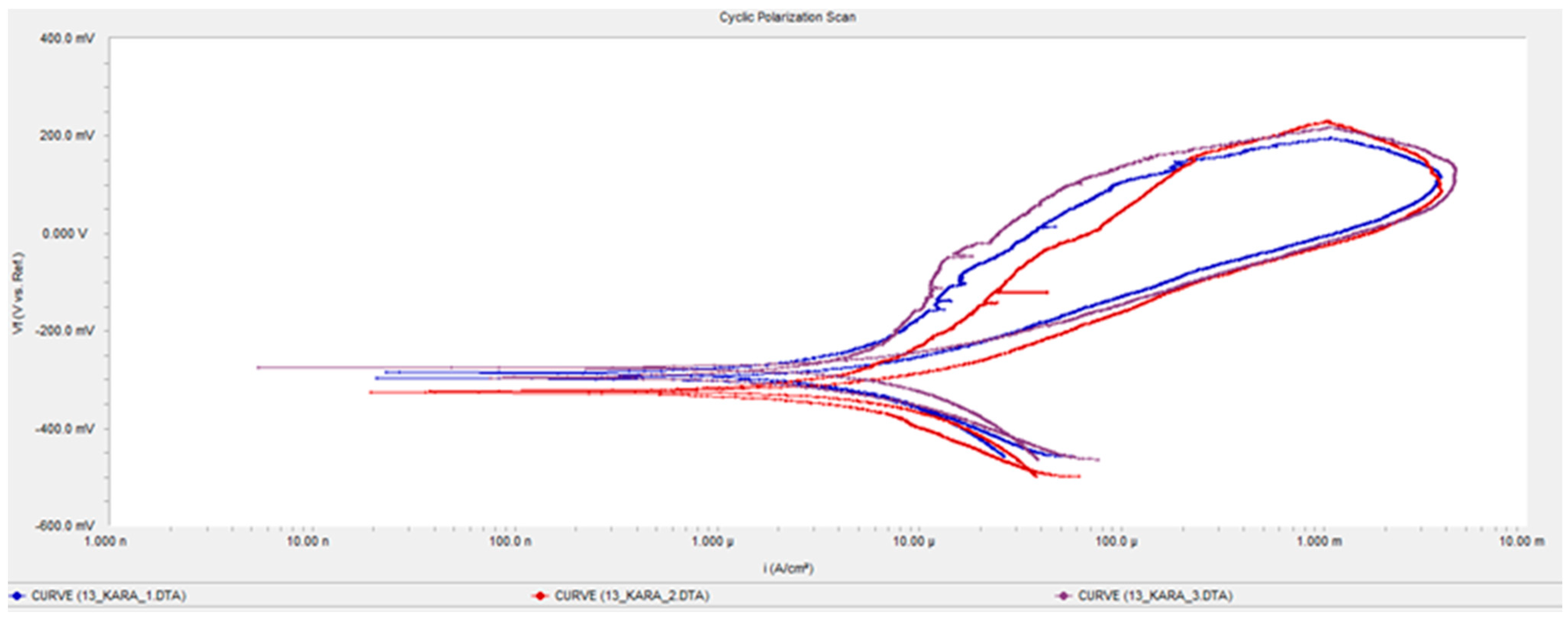
3.5.1. WC-Co (83-17) Coating

From the polarization curves shown in Figure 12, the initial low slope after the Ecorr point indicates a current rise due to the initiation of active corrosion processes. The presence of a passive region at about 0.7–1 mA/cm2 suggests the formation of a protective oxide film on the surface of the coating. This film hinders further corrosion, leading to a stable current density over a range of potentials. The reverse curves show lower currents than the forward curves which reinforces the existence of a passive region, meaning that the protective oxide film remains intact even when the potential is decreased. The third test not showing a passive area could indicate that the passive film may have been less stable or that passivation would occur at a higher current density, potentially due to variations in surface conditions or the testing environment.
The SEM/EDS analysis of the corroded surface (Figure 13), particularly the presence of chlorine and oxygen distributed across the surface, confirms that the coating has undergone general corrosion. The fact that chlorine is concentrated preferably on the carbide’s surface suggests that chloride ions in seawater may preferentially attack the carbide phases or accumulate in these areas due to electrochemical reactions.
The low Icorr values (mean value: 18.4 × 10⁻⁶ A/cm2), indicate that the WC-Co (83-17) coating exhibits excellent corrosion resistance in seawater. The coherent oxide film that develops on the surface plays a crucial role in providing this corrosion resistance. As long as this film remains intact and adherent to the substrate, it will effectively protect against further corrosive attacks. In summary, the WC-Co (83-17) coating’s corrosion resistance is characterized by the formation of a stable and protective oxide film in a seawater environment, demonstrated by the passive region in the polarization curves [33]. The presence of chlorine and oxygen across the surface indicates that general corrosion has occurred, but the low corrosion current values suggest that the coating is effectively resisting further degradation, positioning it as a good material for applications where high corrosion resistance is required, such as in marine environments.

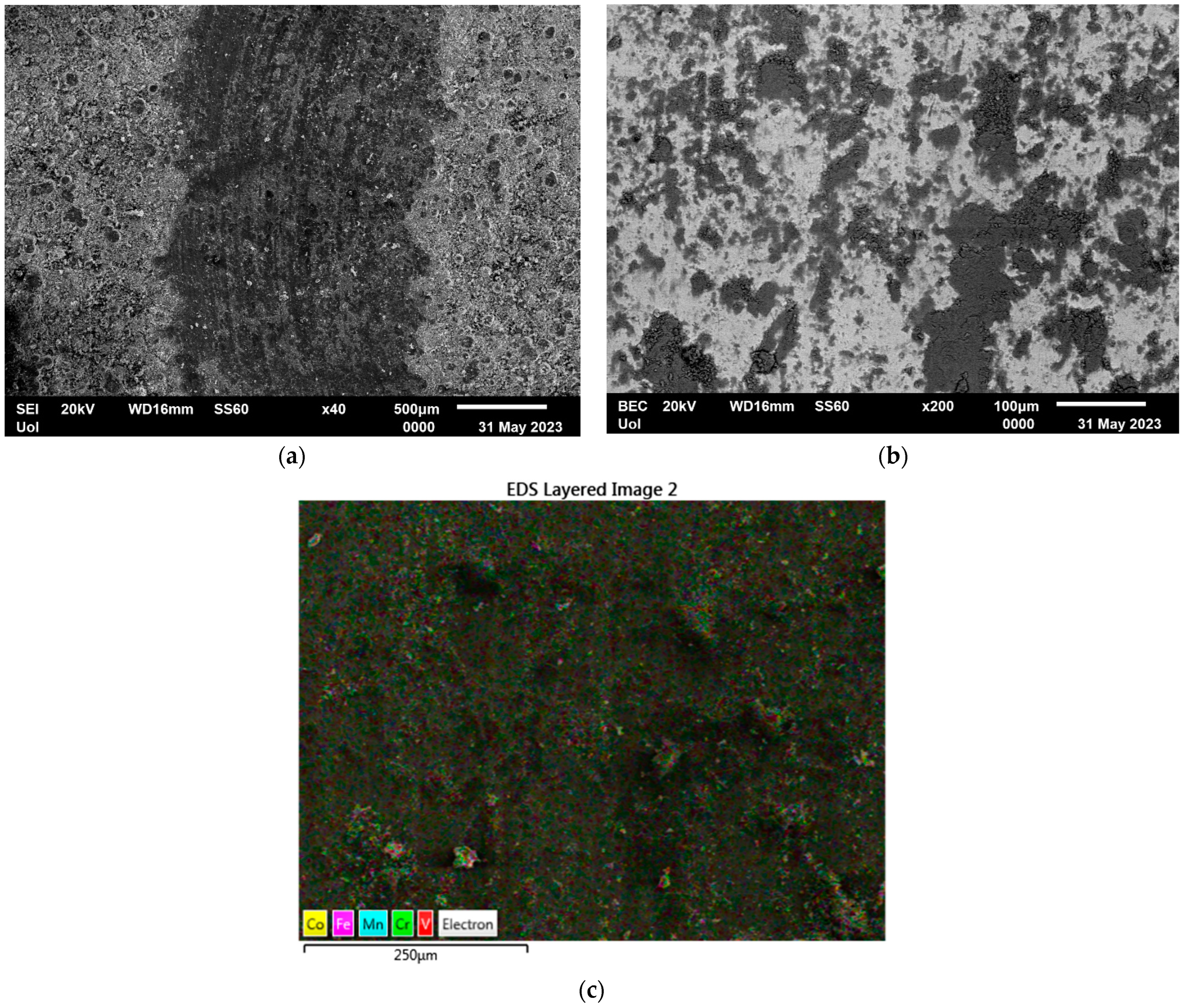
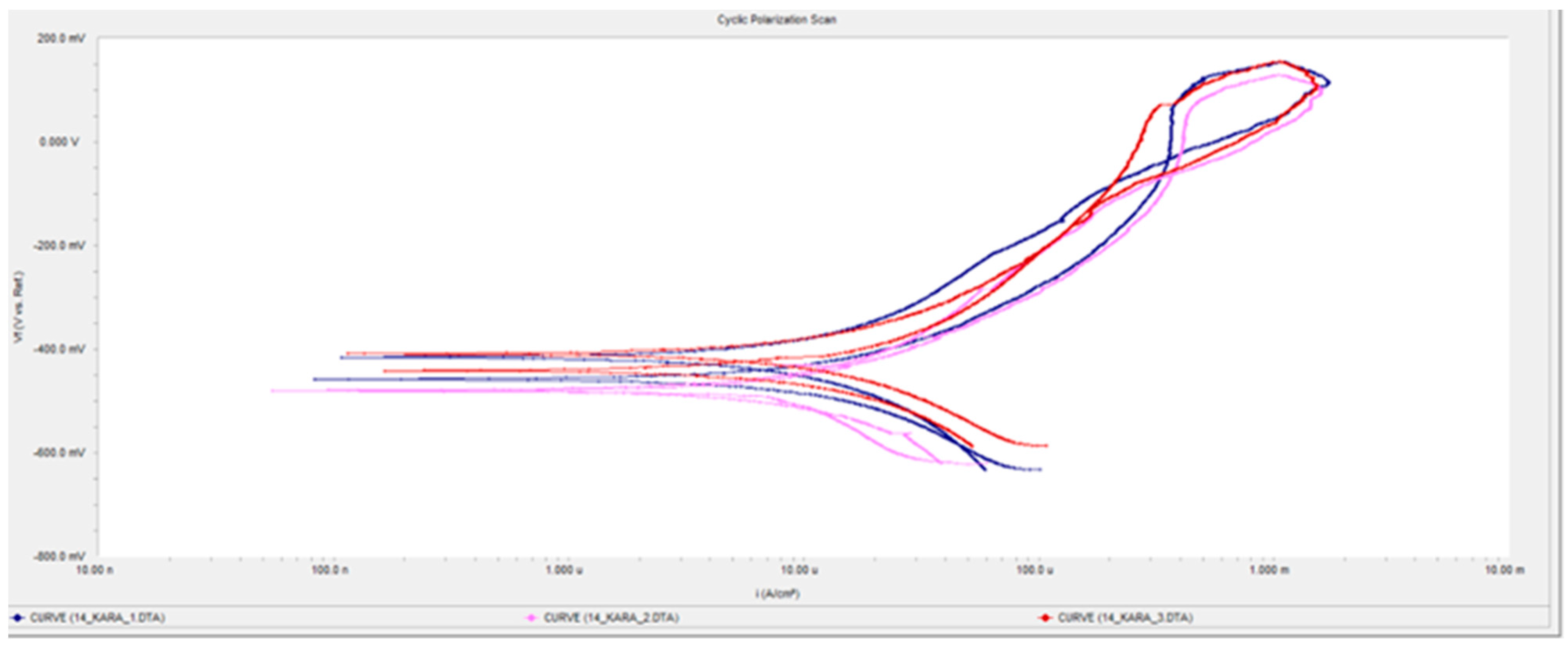
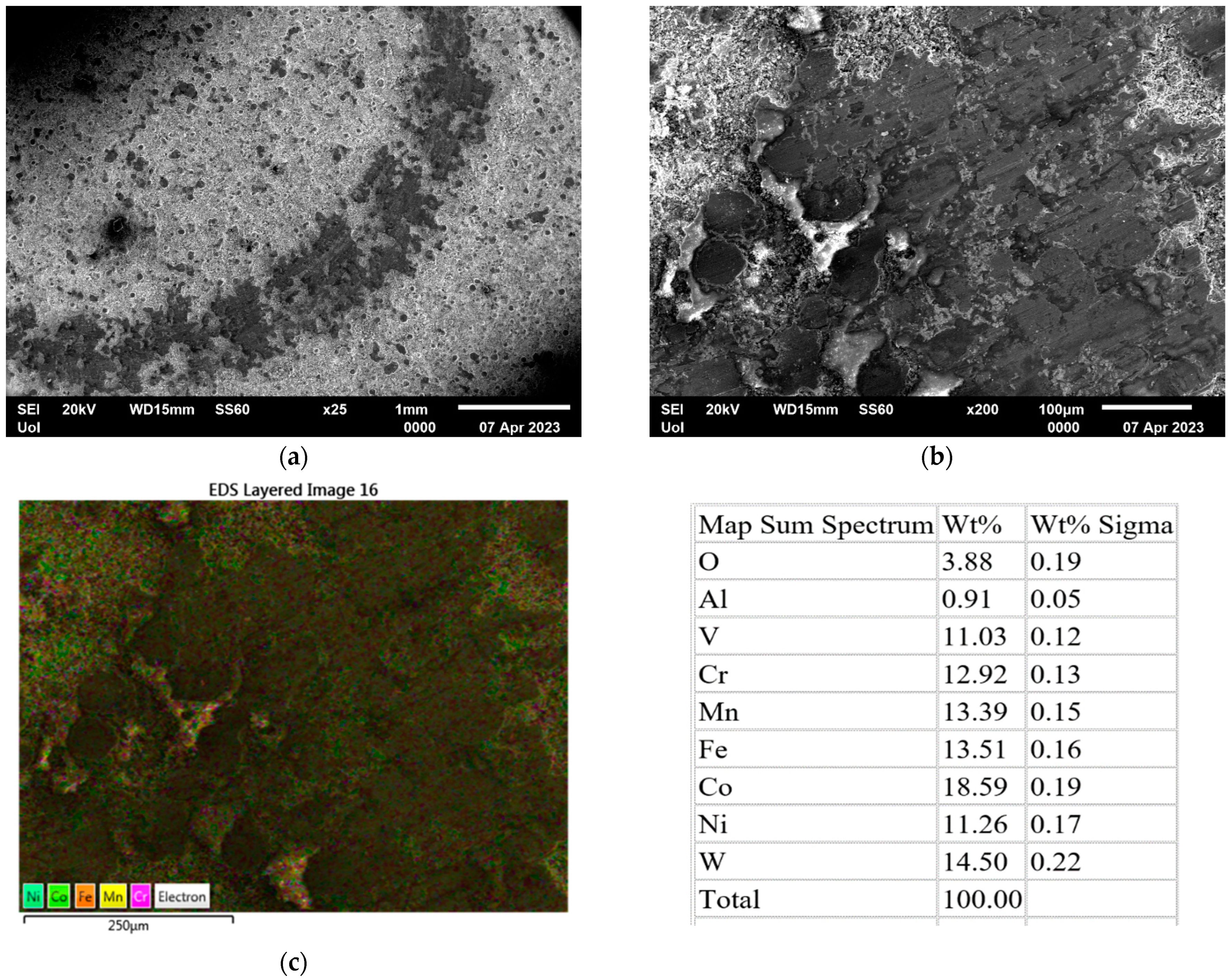
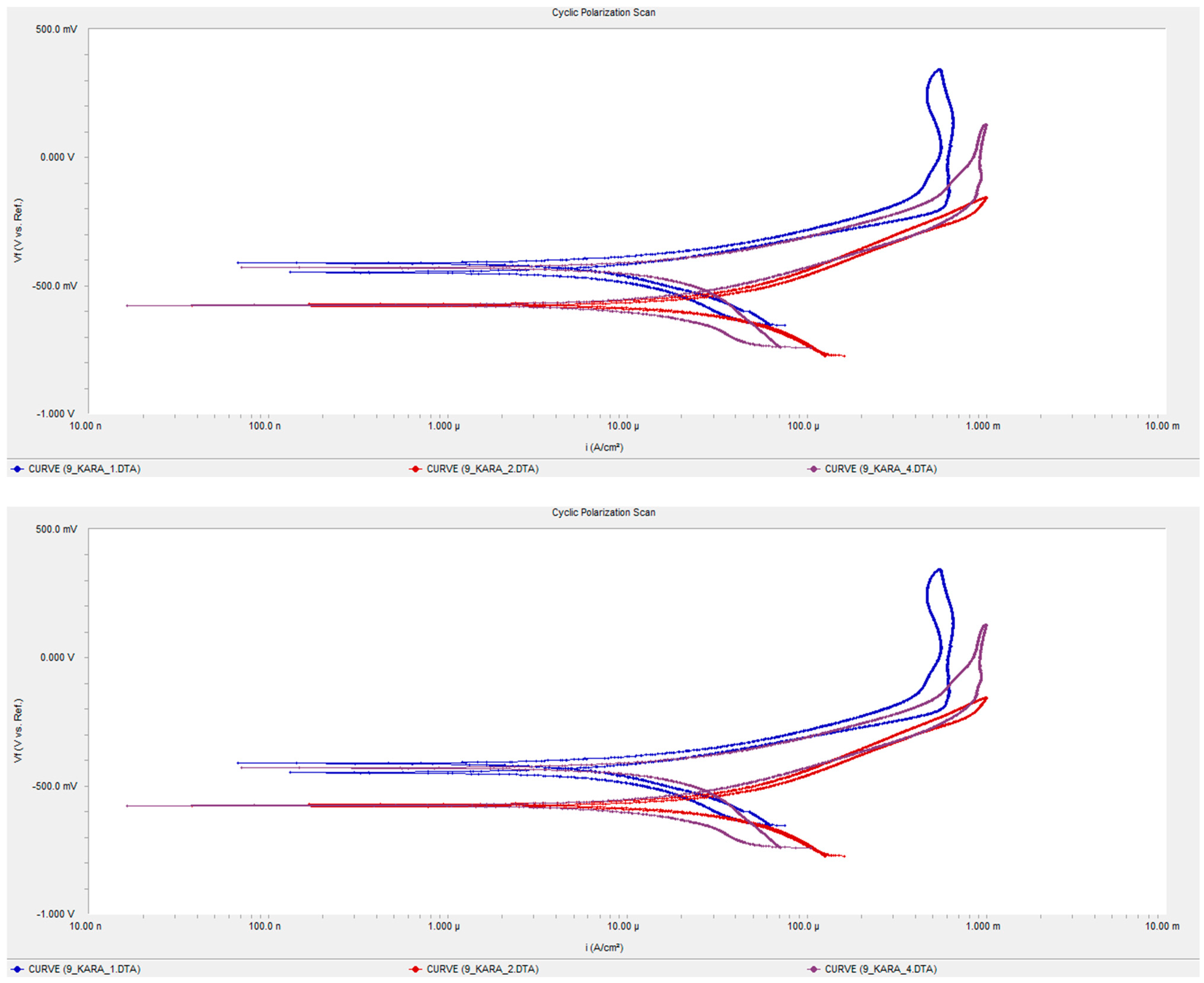
3.5.2. CoCrFeMnNi0.8V Coating

Figure 14 presents examples of the polarization curves of the CoCrFeMnNi0.8V coating system.
The polarization curves are highly repeatable, suggesting the consistent corrosion behavior for the CoCrFeMnNi0.8V coating. The forward curve shows a current rise after the Ecorr point, which is a sign of the onset of active corrosion but is followed by a decrease, indicating the formation of protective oxides. The lower currents in the reverse polarization curves compared to the forward curves suggest the passivation of the coating, which is indicative of good corrosion resistance [34].
The SEM images (Figure 15) show some phase segregation/formation on the surface, likely of uncorroded and oxidized particles. The presence of segregated HEA areas free of chloride signifies good corrosion resistance. The EDS analysis does not show significant chlorine concentration on the CoCrFeMnNi0.8V particles, as shown in Table 3, further confirming their resistance to corrosion. Localized corrosion is present, potentially due to poor interface quality between unmelted atomized HEA particles. The low Icorr values (mean value: 4.06 × 10⁻⁶ A/cm2) demonstrate excellent corrosion resistance, particularly in comparison to Inconel 625 (25.7 × 10⁻⁶ A/cm2), a material known for its superior corrosion resistance [34,35].
In conclusion, the CoCrFeMnNi0.8V coating demonstrates an excellent ability to resist corrosion, attributed to the formation of protective oxides and the inherent corrosion resistance of the HEA composition. Further improvements in the application process could potentially lead to even better performance, solidifying the CoCrFeMnNi0.8V coating as a robust choice for marine and other corrosive environments.

3.5.3. CoCrFeMnNi0.8V + WC-Co Coating

Figure 16 presents examples of the polarization curves of the CoCrFeMnNi0.8V/WC-Co coating system.
The polarization curves show good repeatability, indicating consistent corrosion resistance of the coating. The forward curves suggest that after initial oxidation (Ecorr), there is a continuous rise in current followed by a decrease, hinting at the formation of a protective oxide layer. The decrease in current following the rise could be indicative of passivation, which protects the surface from further corrosion. Reverse polarization curves shape at higher currents, suggesting a degree of localized corrosion.
The coating presents good general corrosion resistance, evidenced by the higher Ecorr of the samples during reverse polarization. Low Icorr values in comparison to Inconel 625 imply excellent corrosion resistance in a seawater environment [33,34,35]. The SEM images (Figure 17) display phase segregation on the surface, likely due to unmelted particles and oxide formation. The EDS data confirm the presence of oxides and indicate that WC-Co has been attacked by chlorine, whereas the CoCrFeMnNi0.8V particles show no trace of chlorine, suggesting their superior resistance.
Local corrosion is attributed to possible poor interfaces between HEA particles and carbides, as mentioned in the microstructure analysis. The SEM-EDS point analysis suggests that the segregation and oxide particles on the surface might be influencing the corrosion process, as they are associated with areas of localized corrosion.
The composite coating, consisting of 75% CoCrFeMnNi0.8V and 25% WC-Co, shows a good balance of wear and corrosion resistance, making it suitable for use in harsh environments like seawater. The presence of coherent oxides developed on the surface suggests that the coating’s corrosion mechanism involves the formation of a protective barrier that mitigates further material degradation.
In conclusion, the CoCrFeMnNi0.8V + WC-Co composite coating demonstrates strong corrosion resistance, comparable to high-performance alloys like Inconel 625, and shows potential for improved performance with optimization of the coating process. The coating’s microstructure, phase composition, and oxide formation play significant roles in its overall corrosion resistance in seawater environments.
In general, as shown in Table 4, the CoCrFeMnNi0.8V coating has the lowest corrosion current density, indicating the best corrosion resistance among the three, despite a higher Ecorr than the composite. The composite coating presents a middle ground with a lower Ecorr but a higher Icorr than the CoCrFeMnNi0.8V coating, suggesting it might be more prone to corrosion than the single HEA coating but less so than the WC-Co coating. The WC-Co coating shows the highest corrosion current density, indicating that it has the least corrosion resistance among the three. However, the passivation behavior suggests that after the initial corrosion, it can form a protective layer to slow down further corrosion.

3.5.4. Summary of the Corrosion Response of the Produced Coatings

The WC-Co (83-17) coating exhibits a passive region in the polarization curve, indicating the formation of a protective oxide film, which is crucial for corrosion resistance. The SEM/EDS analysis shows general corrosion with chlorine and oxygen distributed across the surface, particularly on carbides, suggesting a targeted attack by chloride ions.
The CoCrFeMnNi0.8V coating shows consistent behavior with a decrease in current after initial oxidation, suggesting protective oxide formation and good corrosion resistance. The SEM/EDS analysis indicates phase segregation but a low chlorine concentration on particles, implying resistance to chloride attacks.
The composite coating presents consistent resistance with the possibility of localized corrosion due to poor interface quality between HEA particles and carbides. The SEM/EDS analysis reveals phase segregation and oxide formation, with WC-Co being more prone to chlorine attacks compared to CoCrFeMnNi0.8V particles.

4. Conclusions

Enhanced corrosion resistance: The composite coating combines the strengths of both materials, offering a robust barrier against corrosion, especially in chloride-rich environments like seawater.
Protective oxide formation: Both components contribute to the formation of a protective oxide layer, which is crucial in mitigating further material degradation.
Balanced wear and corrosion resistance: The composite nature of the coating provides a synergy that balances wear resistance (from WC-Co) and corrosion resistance (from CoCrFeMnNi0.8V), making it suitable for application in harsh conditions.
In conclusion, the composite HEA + WC-Co coating exhibits promising characteristics for applications requiring both high corrosion resistance and durability, particularly in marine environments. The combination of the HEA’s inherent corrosion-resistant properties and WC-Co’s wear resistance makes this composite coating a significant advancement in protective coatings technology.

Author Contributions

Conceptualization, S.K. (Spyros Kamnis), A.E.K. and E.G.; methodology, S.K. (Spyros Kamnis), S.K. (Stavros Kiape), A.E.K., E.G., M.G. and T.E.M.; validation, S.K. (Spyros Kamnis), S.K. (Stavros Kiape), A.E.K., E.G. and M.G.; formal analysis, S.K. (Spyros Kamnis), S.K. (Stavros Kiape), A.E.K. and E.G.; investigation, S.K. (Stavros Kiape), M.G. and S.K. (Spyros Kamnis); resources, S.K. (Spyros Kamnis), A.E.K. and T.E.M.; data curation, S.K. (Stavros Kiape), A.E.K. and E.G.; writing—original draft preparation, S.K. (Stavros Kiape), S.K. (Spyros Kamnis) and A.E.K.; writing—review and editing, S.K. (Stavros Kiape), S.K. (Spyros Kamnis) and A.E.K.; visualization, S.K. (Stavros Kiape) and S.K. (Spyros Kamnis); supervision, A.E.K., E.G. and S.K. (Spyros Kamnis). All authors have read and agreed to the published version of the manuscript.

Funding

This research received no external funding.

Data Availability Statement

Data will be available at demand.

Conflicts of Interest

The authors declare no conflicts of interest.

References

  1. Yeh, J.W.; Chen, S.K.; Lin, S.J.; Gan, J.Y.; Chin, T.S.; Shun, T.T.; Tsau, C.H.; Chang, S.Y. Nanostructured high-entropy alloys with multiple principal elements: Novel alloy design concepts and outcomes. Adv. Eng. Mater. 2004, 6, 299–303. [Google Scholar] [CrossRef]
  2. Cantor, B.; Chang, I.; Knight, P.; Vincent, A. Microstructural development in equiatomic multicomponent alloys. Mater. Sci. Eng. A 2004, 375–377, 213–218. [Google Scholar] [CrossRef]
  3. Li, C.; Li, J.; Zhao, M.; Jiang, Q. Effect of alloying elements on microstructure and properties of multiprincipal elements high-entropy alloys. J. Alloys Compd. 2009, 475, 752–757. [Google Scholar] [CrossRef]
  4. Tsai, M.-H.; Tsai, R.-C.; Chang, T.; Huang, W.-F. Intermetallic Phases in High-Entropy Alloys: Statistical Analysis of their Prevalence and Structural Inheritance. Metals 2019, 9, 247. [Google Scholar] [CrossRef]
  5. Guruvidyathri, K.; Vaidya, M.; Murty, B. Challenges in design and development of high entropy alloys: A thermodynamic and kinetic perspective. Scr. Mater. 2020, 188, 37–43. [Google Scholar] [CrossRef]
  6. Wen, C.; Zhang, Y.; Wang, C.; Xue, D.; Bai, Y.; Antonov, S.; Dai, L.; Lookman, T.; Su, Y. Machine learning assisted design of high entropy alloys with desired property. Acta Mater. 2019, 170, 109–117. [Google Scholar] [CrossRef]
  7. Kamnis, S.; Sfikas, A.K.; Gonzalez, S.; Karantzalis, A.E.; Georgatis, E. A New Cooling-Rate-Dependent Machine Learning Feature for the Design of Thermally Sprayed High-Entropy Alloys. J. Therm. Spray Technol. 2022, 32, 401–414. [Google Scholar] [CrossRef]
  8. Wani, I.S.; Bhattacharjee, T.; Sheikh, S.; Bhattacharjee, P.P.; Guo, S.; Tsujι, N. Tailoring Nanostructures and Mechanical Properties of AlCoCrFeNi2.1 Eutectic High Entropy Alloy Using Thermo-Mechanical Processing. Mater. Sci. Eng. A 2016, 675, 99–109. [Google Scholar] [CrossRef]
  9. Slobodyan, M.; Pesterev, E.; Markov, A. A review of high-energy processing techniques applied for additive manufacturing and surface engineering of cemented carbides and cermets. J. Manuf. Process. 2023, 105, 124–186. [Google Scholar] [CrossRef]
  10. Habib, K.; Hamelin, L.; Wenzel, H. A dynamic perspective of the geopolitical supply risk of metals. J. Clean. Prod. 2016, 133, 850–858. [Google Scholar] [CrossRef]
  11. Duchaniya, R.-K.; Pandel, U.; Rao, P. Coatings based on high entropy alloys: An overview. Mater. Today Proc. 2021, 44, 4467–4473. [Google Scholar] [CrossRef]
  12. Li, J.; Huang, Y.; Meng, X.; Xie, Y. A Review on High Entropy Alloys Coatings: Fabrication Processes and Property Assessment. Adv. Eng. Mater. 2019, 21, 1900343. [Google Scholar] [CrossRef]
  13. Sfikas, A.K.; Kamnis, S.; Tse, M.C.H.; Christofidou, K.A.; Gonzalez, S.; Karantzalis, A.E.; Georgatis, E. Microstructural Evaluation of Thermal-Sprayed CoCrFeMnNi0.8V High-Entropy Alloy Coatings. Coatings 2023, 13, 1004. [Google Scholar] [CrossRef]
  14. Karpets, M.V.; Myslyvchenko, O.M.; Makarenko, O.S.; Gorban, V.F.; Krapivka, M.O.; Degula, A.I. Effect of nickel on the structure and phase composition of the VCrMnFeCoNi x high-entropy alloy. J. Superhard Mater. 2015, 37, 182–188. [Google Scholar] [CrossRef]
  15. Santos, R.F.; Ferro Rocha, A.M.; Bastos, A.C.; Cardoso, J.P.; Rodrigues, F.; Fernandes, C.M.; Sacramento, J.; Ferreira MG, S.; Senos AM, R.; Fonseca, C.; et al. The effect of Cr content on the corrosion resistance of WC-Ni-Cr-Mo composites. Int. J. Refract. Met. Hard Mater. 2021, 95, 105434. [Google Scholar] [CrossRef]
  16. Shi, Y.; Yang, B.; Liaw, P.K. Corrosion-Resistant High-Entropy Alloys: A Review. Metals 2017, 7, 43. [Google Scholar] [CrossRef]
  17. Katranidis, V.; Gu, S.; Cox, D.C.; Whiting, M.J.; Kamnis, S. FIB-SEM sectioning study of decarburization products in the microstructure of HVOF-sprayed WC-Co coatings. J. Ther. Spray Technol. 2018, 27, 898–908. [Google Scholar] [CrossRef]
  18. Chivavibul, P.; Watanabe, M.; Kuroda, S.; Shinoda, K. Effects of carbide size and Co content on the microstructure and mechanical properties of HVOF-sprayed WC–Co coatings. Surf. Coat. Technol. 2007, 202, 509–521. [Google Scholar] [CrossRef]
  19. Liu, Y.; Hang, Z.; Xi, N.; Chen, H.; Ma, C.; Wu, X. Erosion-Corrosion Behavior of HVOF WC-Co Coating in Cl and SO42− Containing Solutions. Appl. Surf. Sci. 2018, 431, 55–59. [Google Scholar] [CrossRef]
  20. Guo, Y.; Li, Y.; Liu, Y.; Zhang, H. The impact of geopolitical relations on the evolution of cobalt trade network from the perspective of industrial chain. Resour. Policy 2023, 85, 103778. [Google Scholar] [CrossRef]
  21. Katranidis, V.; Gu, S.; Reina, T.R.; Alpay, E.; Allcock, B.; Kamnis, S. Experimental Study of High-Velocity Oxy-Fuel Sprayed WC-17Co Coatings Applied on Complex Geometries. Part B: Influence of Kinematic Spray Parameters on Microstructure, Phase Composition and Decarburization of the Coatings. Surf. Coat. Technol. 2017, 328, 499–512. [Google Scholar] [CrossRef]
  22. Katranidis, V.; Kamnis, S.; Allcock, B.; Gu, S. Effects and Interplays of Spray Angle and Stand-off Distance on the Sliding Wear Behavior of HVOF WC-17Co Coatings. J. Ther. Spray Technol. 2019, 28, 514–534. [Google Scholar] [CrossRef]
  23. Sahraoui, T.; Guessasma, S.; Jeridane, M.A.; Hadji, M. HVOF sprayed WC–Co coatings: Microstructure, mechanical properties and friction moment prediction. Mater. Des. 2010, 31, 1431–1437. [Google Scholar] [CrossRef]
  24. Wang, H.; Qiu, Q.; Gee, M.; Hou, C.; Liu, X.; Song, X. Wear resistance enhancement of HVOF-sprayed WC-Co coating by complete densification of starting powder. Mater. Des. 2020, 191, 108586. [Google Scholar] [CrossRef]
  25. Lobel, M.; Lindner, T.; Mehner, T.; Rymer, L.-M.; Bjorklund, S.; Joshi, S.; Lampke, T. Microstructure and Corrosion Properties of AlCrFeCoNi High Entropy Alloy Coatings Prepared by HVAF and HVOF. J. Therm. Spray Technol. 2021, 31, 247–255. [Google Scholar] [CrossRef]
  26. Sobolev, V.V.; Guilemany, J.M. Oxidation of coatings in thermal spraying. Mater. Lett. 1998, 37, 231–235. [Google Scholar] [CrossRef]
  27. Kawakita, J.; Isoyama, K.; Kuroda, S.; Yumoto, H. Effects of deformability of HVOF sprayed copper particles on the density of resultant coatings. Surf. Coat. Technol. 2006, 200, 4414–4423. [Google Scholar] [CrossRef]
  28. Meghwal, A.; Anupam, A.; Murty, B.S.; Berndt, C.C.; Kottada, R.S.; Ang, A.S.M. Thermal Spray High-Entropy Alloy Coatings: A Review. J. Therm. Spray Technol. 2020, 29, 857–893. [Google Scholar] [CrossRef]
  29. Xie, Z.; Zhang, C.; Wang, R.; Li, D.; Zhang, Y.; Li, G.; Lu, X. Microstructure and wear resistance of WC/Co-based coating on copper by plasma cladding. J. Mater. Res. Technol. 2021, 15, 821–833. [Google Scholar] [CrossRef]
  30. Zum Gahr, K.H. Wear by hard particles. Tribol. Int. 1998, 31, 587–596. [Google Scholar] [CrossRef]
  31. Rajinikanth, V.; Venkateswarlu, K. An investigation of sliding wear behaviour of WC–Co coating. Tribol. Int. 2011, 44, 1711–1719. [Google Scholar] [CrossRef]
  32. Peng, Y.; Zhang, W.; Li, T.; Zhang, M.; Liu, B.; Liu, Y.; Wang, L.; Hu, S. Effect of WC content on microstructures and mechanical properties of FeCoCrNi high-entropy alloy/WC composite coatings by plasma cladding. Surf. Coat. Technol. 2020, 385, 125326. [Google Scholar] [CrossRef]
  33. Ghosh, G.; Sidpara, A.; Bandyopadhyay, P.P. Understanding the role of surface roughness on the tribological performance and corrosion resistance of WC-Co coating. Surf. Coat. Technol. 2019, 378, 125080. [Google Scholar] [CrossRef]
  34. Meghwal, A.; Anupam, A.; Luzin, V.; Schulz, C.; Hall, C.; Murty, B.S.; Kottada, R.S.; Berndt, C.C.; Ang, A.S.M. Multiscale mechanical performance and corrosion behaviour of plasma sprayed AlCoCrFeNi high-entropy alloy coatings. J. Alloys Compd. 2021, 854, 157140. [Google Scholar] [CrossRef]
  35. Ahmed, N.; Bakare, M.S.; McCartney, D.G.; Voisey, K.T. The effects of microstructural features on the performance gap in corrosion resistance between bulk and HVOF sprayed Inconel 625. Surf. Coat. Technol. 2010, 204, 2294–2301. [Google Scholar] [CrossRef]
Figure 1. Microstructure (BSE mode) and elemental map of CoCrFeMnNi0.8V powder, Ref. [13].
Jcs 08 00120 g001
Figure 2. (a) The SEM secondary electron image of the composite feedstock powder, (b) only WC-Co (83-17) powder.
Jcs 08 00120 g002
Figure 3. (a) WC-Co 83-17 coating microstructure, (b) EDX of coating cross section.
Jcs 08 00120 g003
Figure 4. X-ray diffraction (XRD) of WC-Co coating.
Jcs 08 00120 g004
Figure 5. (a) CoCrFeMnNi0.8V coating microstructure, (b) XRD of coated material.
Jcs 08 00120 g005aJcs 08 00120 g005b
Figure 6. (a) A cross section of the CoCrFeMnNi0.8V + WC-Co composite coating (b) a higher magnification of the composite coating indicating the involved phases. The yellow frame indicates the locus used in the analysis presented in Figure 7.
Jcs 08 00120 g006
Figure 7. An EDS line scan across a HEA splat and the related element distribution.
Jcs 08 00120 g007
Figure 8. The X-ray diffraction (XRD) of the sprayed coating.
Jcs 08 00120 g008
Figure 9. The wear tracks of the WC-Co coating ((a) lower, (b) higher magnification) along with the related EDS chemical mapping (c).
Jcs 08 00120 g009
Figure 10. The wear tracks of the CoCrFeMnNi0.8V coating ((a) lower, (b) higher magnification) along with the related EDS chemical mapping (c).
Jcs 08 00120 g010
Figure 11. The composite coating wear track ((a) lower, (b) higher magnification) and the related EDS chemical mapping (c).
Jcs 08 00120 g011
Figure 12. Examples of the polarisation curves of the WC-Co coating system.
Jcs 08 00120 g012
Figure 13. The SEM/EDS analysis from the corroded surface of the coating.
Jcs 08 00120 g013
Figure 14. The polarization curves of the CoCrFeMnNi0.8V coating.
Jcs 08 00120 g014
Figure 15. The SEM/EDS analysis from the corroded surface of the HEA coating.
Jcs 08 00120 g015
Figure 16. Polarization curves of the composite coating.
Jcs 08 00120 g016
Figure 17. The SEM/EDS analysis from the corroded surface of the composite coating.
Jcs 08 00120 g017
Table 1. Chemical composition (at%) of gas-atomized CoCrFeMnNi0.8V powder.
VCrMnFeCoNi
Nominal17.217.217.217.217.213.8
Powder15.9 ± 0.218.1 ± 0.217.9 ± 0.417.1 ± 0.417.3 ± 0.213.8 ± 0.3
Table 2. Average specific wear rates for different coating materials.
Coating SystemAverage Specific Wear Rate (×10−7 g/Nm)Coefficient of FrictionHardness (HV)Wear Mechanism
WC-Co (83-17)0.80.2991134Abrasive, Fatigue
CoCrFeMnNi0.8V7.130.595500Oxidative, Delamination, Abrasive, Fatigue
Composite (HEA-75%-WC-Co-25%)1.970.541530Oxidative, Delamination, Abrasive, Fatigue
Table 3. The atomic concentration of the elements of the corroded coating.
ElementAtomic %
Na2.83
Cl1.46
V14.96
Cr17.82
Mn15.88
Fe17.26
Co16.74
Ni13.04
Total100.0
Table 4. Polarization testing comparative summary.
Coating SystemEcorr (mV)Icorr (×10−6 A/cm2)Remarks
WC-Co (83/17)−534.0018.4General corrosion. Passivation.
CoCrFeMnNi0.8V−302.004.06Local corrosion. Very low Icorr.
CoCrFeMnNi0.8V + WC-Co (83/17) (75–25)% Mix−448.6010.80Local corrosion. Very low Icorr
Disclaimer/Publisher’s Note: The statements, opinions and data contained in all publications are solely those of the individual author(s) and contributor(s) and not of MDPI and/or the editor(s). MDPI and/or the editor(s) disclaim responsibility for any injury to people or property resulting from any ideas, methods, instructions or products referred to in the content.

