Abstract
Short basalt fibres (BFs) have recently gained significant interest in the building materials sector due to their superior mechanical characteristics and cheaper manufacturing cost than other fibre types. Drying shrinkage and the early-age cracking of concrete are the root cause of many durability issues in the long run. Including small dosages of fibres within concrete composites has been shown as an effective technique to minimise drying shrinkage rates and reduce the crack widths developed due to plastic shrinkage cracking. Nevertheless, limited research studies have investigated the influence of short and long BFs with different dosages on the drying shrinkage rates and early-age cracking of geopolymer composites. In the present study, self-compacting geopolymer concrete (SCGC) using fly ash and slag as the binder is mixed with anhydrous sodium metasilicate powder as an alkali-activator. The study aims to investigate the influence of short (12 mm), long (30 mm) and hybrid-length (1:3 (short/long)) BFs with 1%, 1.5% and 2% dosages on the drying shrinkage properties and plastic shrinkage cracking of SCGC. The study results showed that adding BFs to SCGC reduces the drying shrinkage rates compared to plain SCGC, and SCGC reinforced with a 2% dosage of hybrid-length BFs recorded the lowest drying shrinkage rate. Two methods were used to measure crack widths: manual measurement (crack width gauge) and image analysis. No plastic shrinkage cracks were identified in mixes reinforced with 12 mm (1.5% and 2% dosages), 30 mm and hybrid-length BFs.
1. Introduction
Cementitious concrete is the fundamental foundation of the modernising globe and unequivocally one of the most synthetic utilised materials in the building sector [1]. By 2050, cement production is anticipated to increase by 12–23% due to urbanisation and infrastructure expansion [2], which will consequently increase CO2 emissions by 4% [3]. The World Green Building Council (WorldGBCs) urges the construction sector to adopt sustainable construction materials to approach decarbonisation by 2050 [4,5].
Geopolymer resins were first pioneered as a novel binder group by Joseph Davidovits in 1979 [6]. The physical properties of geopolymer resins vary to meet the needs of wide applications in the building, automotive and aerospace industries [1]. Geopolymer concrete is synthesised by mixing chemical alkaline solutions such as sodium hydroxide and sodium silicate with by-products, including fly ash, slag, rice husk ash, metakaolin, etc. [7]. Utilising by-products in geopolymer concrete production minimises the by-products’ adverse effect on the environment [1] and reduces CO2 emissions by 80% compared to cementitious concrete [8]. Multiple research studies have reported that geopolymer concrete has comparable characteristics to cementitious concrete, such as adequate compressive and flexural strength [9,10], similar splitting tensile strength [10], and an outstanding bond with steel reinforcement [11,12]. Geopolymer concrete possesses improved durability and mechanical properties under extreme heat compared to cementitious concrete because of its structure’s stable connection link [13]. Better chemical resistance to sulfuric acid is more associated with geopolymer concrete than cementitious concrete [14]. Geopolymer concrete, primarily made of fly ash and slag, has a comparable freeze-thaw resistance to cementitious concrete [15].
Traditional geopolymer concrete requires high-heat curing, between 60 °C and 85 °C, for 24 h immediately after casting to gain strength [4,16]. Additionally, the alkali-activator solutions used in the geopolymer mix require special handling, and the early preparation of the solution is needed 24 h before casting [17,18]. The two hurdles mentioned above limit the expansion of geopolymer concrete beyond the precast elements in the construction industry. A new mix of self-compacted geopolymer concrete (SCGC) was recently developed at Deakin University, Australia, and is mainly produced by mixing by-products, including fly ash, slag and micro ash, with solid anhydrous sodium metasilicate powder as an alkali-activator [10]. The developed mix achieves a compressive and splitting tensile strength of 40 MPa and 3 MPa, respectively, under ambient temperature [10]. SCGC may be a potential alternative to cementitious concrete as all SCGC’s binder constituents are solid, and no heat curing is required to achieve good mechanical properties.
Even though the production ease of SCGC makes it more practicable for in-situ applications, a significant concern regarding the shrinkage property of fly-ash–slag-based geopolymer concrete (FASGC) has been identified. High shrinkage in concrete is an essential concern since it leads to the formation of cracks in concrete composition, which negatively reflects on its durability characteristics in the long term [19]. Increasing the slag content in FASGC causes an increase in drying shrinkage rates, and the formation of significant efflorescence [19]. According to Lee et al. (2013) [20], including slag content in geopolymer concrete above a 25% ratio to fly ash results in significant cracks due to drying shrinkage and consequently decreases compressive strength. Additionally, using more than 30% slag in a fly ash geopolymer concrete mixture increases the possibility of crack formation due to plastic shrinkage, as shown in Figure 1 [20]. The high percentage of slag content (more than 50%) in fly ash geopolymer concrete results in rapid efflorescence occurrence and, consequently, higher shrinkage behaviour [21]. The curing temperature of fly ash/slag geopolymer concrete significantly impacts drying shrinkage [19]. A study conducted by Marjanović et al. (2015) [22] examined the effect of the concentration of activator modulus and curing temperature on the performance of fly ash/slag with a 75/25 ratio in terms of setting time and drying shrinkage. The study results showed that FASGC cured at room temperature (25 °C) has approximately a five-times-higher drying shrinkage value (≈4500 μ/mm) compared to the same mixture cured for 24 h after casting at 95 °C (≈1000 μ/mm). Regular concrete has a drying shrinkage equal to (≈ 800 μ/mm), comparable to heat-cured fly ash/slag geopolymer concrete [22]. Geopolymer concrete has a significantly higher drying shrinkage than cementitious concrete, as water is not directly incorporated into the binder formation [19]. Hence, considerable water remains chemically unbonded to the concrete and susceptible to evaporation [23]. High shrinkage behaviour in concrete leads to the development of tension cracks and consequently weakens the concrete strength, affecting its durability in the long run. Therefore, the shrinkage behaviour of the geopolymer concrete mixture must be reduced to comply with cementitious concrete shrinkage specifications.
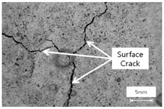
Figure 1.
Surface cracks developed in fly ash/slag geopolymer concrete [20].
For decades, the concrete industry has strived to adopt sustainable construction techniques to enhance concrete properties and durability by employing natural and innovative constituents. Incorporating short fibres into geopolymer concrete has shown to be an efficient technique for reducing drying shrinkage and plastic shrinkage cracking [23,24,25,26,27,28,29,30]. The influence of micro steel fibres and polypropylene fibres with volume contents of (0.5, 1, 2, 3, 4)% on fly ash-based geopolymer concrete’s mechanical properties and drying shrinkage was investigated [24]. Using both fibre types in geopolymer concrete effectively reduced drying shrinkage rates. Gao et al. (2017) [26] studied the effect of 6 mm and 13 mm steel fibres, up to 1% of total volume, on the workability, mechanical properties, porosity and drying shrinkage of geopolymer concrete. It was observed that 1% of short steel fibres performed slightly better than long steel fibres, as the drying shrinkage of geopolymer concrete decreased by 32% with short fibres and 27.6% with long fibres [26]. Abdollahnejad et al. (2017) [25] investigated the effect of different glass fibre lengths—10 mm, 20 mm and 30 mm—with varying percentages of volume (0.5, 1, 1.5, 2)% on the mechanical properties and drying shrinkage of self-compacting fly ash/slag geopolymer mortar and cementitious mortar. The study results indicate that adding glass fibres to fly ash/slag geopolymer mortar significantly reduces the drying shrinkage and improves the mechanical properties. The study reported that 1.5% glass fibres are the optimum dosage, as beyond this dosage, the drying shrinkage of geopolymer concrete is not affected or may decrease [25]. Abdollahnejad et al. (2018) [30] reported that adding steel fibres, PVA fibres and polypropylene fibres independently to slag-based geopolymer concrete considerably reduces shrinkage and prevents cracks formation. Including polypropylene fibres (PP) with a volume content of 0.75% in calcined kaolin–fly-ash-based geopolymer reduces the drying shrinkage by approximately 30% compared to plain mix [27]. Using fibres to strengthen the mix compositions is an efficient and relatively simple technique to decrease shrinkage and crack propagation compared to other methods.
Aside from the fibres stated above, basalt fibres (BFs) have been drawing researchers’ attention owing to their cheap manufacturing cost [31], non-corrosive properties [32], sustainability [32,33], good mechanical characteristics [32,34,35,36], and excellent chemical and temperature stability [31,34,37,38,39,40,41]. Adding micro-basalt fibres to fly ash geopolymer paste improves the mechanical properties and reduces the drying shrinkage of the mix [42]. The complete replacement of fly ash with micro-basalt fibres in the paste reduces drying shrinkage from approximately 30,000 microstrains to 10,000 microstrains [42]. Incorporating micro-basalt fibres into fly ash geopolymer paste densifies the calcium content. It results in the formation of a hybrid CNASH gel that improves the chemical bond strength and reduces the drying shrinkage [42].
Similarly, a 70% reduction in drying shrinkage was observed in geopolymer paste, where micro-basalt fibres replaced rice-husk ash entirely [43]. Xu et al. (2021) [44] evaluated the effect of two basalt fibre lengths—3 mm and 6 mm—on the drying shrinkage of slag–fly ash geopolymer grouting material. The results indicate that increased basalt fibre volume content in the mix reduces the drying shrinkage. The long fibres showed better performance in reducing the drying shrinkage than short fibres [44]. Although studies showed that including fibres can minimise the drying shrinkage property and crack propagation in geopolymer composites, there is still a significant knowledge gap regarding the performance of BF-reinforced geopolymer concrete, especially self-compacted geopolymer concrete. Moreover, further research is required to assess the effect of the hybridisation of short and long basalt fibres on the drying shrinkage and crack propagation of self-compacted geopolymer concrete.
Research Significance
Early-age cracking due to plastic and drying shrinkage is a significant cause of durability issues in concrete. Researchers have recently explored the impact of fibres on the behaviour of geopolymer composites’ drying shrinkage and crack development, resulting in various advances. Even so, limited studies have investigated the effect of the drying shrinkage and plastic shrinkage cracking of geopolymer composites reinforced with discrete basalt fibres [42,43,44]. The drying shrinkage and mechanical properties of hybrid short-/long-steel-fibre-reinforced geopolymer mortar with volume contents up to 1% were assessed against mono-steel fibre systems [26]. The hybridisation of multiscale steel fibre length showed a slight improvement in the mechanical properties of geopolymer mortar compared to the mono-steel fibre system. Steel fibre hybridisation has no apparent synergetic impact on geopolymer mortar’s drying shrinkage [26]. Heweidak et al. (2022) [1] studied the influence of mono and hybrid short/long basalt fibres on the mechanical properties of self-compacted geopolymer concrete. The study results indicate that increased BF dosage of up to 2% in SCGC enhances the mechanical properties, and mixes reinforced with hybrid short/long BFs showed better mechanical properties than mono-BF systems [1]. SCGC primarily made of fly ash and slag develops high surface-crack tension, as shown in Figure 2. Hence, further investigation is required to study the influence of single and hybrid BF lengths with different dosages of binder weight on the drying shrinkage rate and early-age cracking induced due to plastic shrinkage. The experimental investigation was carried out on SCGC reinforced with two different lengths of basalt fibres—12 mm and 30 mm—and a hybrid mix of the two lengths, with varying dosages of 1%, 1.5% and 2%.
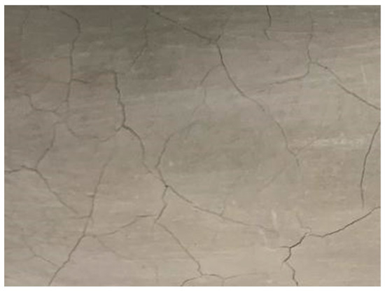
Figure 2.
Surface cracks developed in SCGC.
2. Experimental Section
2.1. Materials and Casting
SCGC comprises fly ash/slag with a ratio of 60/40 and anhydrous sodium metasilicate powder (Na2SiO3) as an alkali-activator and 5% of micro ash is added to reduce the shrinkage and lowering voids and water demand. The water content is 45% of the binder weight [10]. Cement Australia Pty Ltd. supplied fly ash with a high silica ratio that met AS/NZS 3582.1:2016 standards [45]. Micro ash of 3.5 µm fine particle size was incorporated into the mix to increase workability and concrete strength [46,47]. Independent Cement and Lime Pty Ltd. and Redox Ltd. supplied the ground slag and the sodium anhydrous metasilicate powder (Na2SiO3), respectively. The chemical composition of SCGC’s binders is presented in Table 1. Additionally, 12 mm and 30 mm BFs, as illustrated in Figure 3, were added to reinforce the SCGC mixes, with 1%, 1.5% and 2% of binder weight. The physical properties of used BFs are detailed in Table 2. Heweidak et al. (2022) reported that SCGC mixes incorporating a 3:1 ratio of hybrid long-to-short BFs have better mechanical properties than mono-fibre systems. This study uses the same ratio (of 3:1) of long-to-short BFs to investigate the effect on the development of the SCGC’s drying shrinkage and plastic shrinkage cracks compared to mono-fibre systems.

Table 1.
Chemical composition details of SCGC mixture [1].
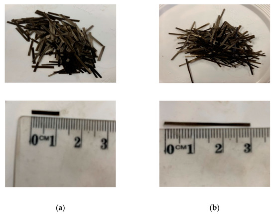
Figure 3.
Short/long basalt fibres of (a) 12 mm and (b) 30 mm were used in the SCGC mixture [1].
Table 2.
Physical properties of basalt fibres [48,49,50,51].
The SCGC mix design is presented in Table 3. Ten SCGC mixes were prepared, including the control mix and nine BF-reinforced SCGC mixes (Table 4). Reinforced SCGC mixes were developed by combining coarse and fine aggregate, all binder constituents, and basalt fibres in a concrete mixer drum for 4 min. Subsequently, water was added to the dry mixture, and the mixing process was continued for approximately 11 min.
Table 3.
Mix design of SCGC (kg per 1 m3).
Table 4.
Designation of mix composition.
A slump flow test was performed to assess the effect of BFs on the fresh-state behaviour of SCGC. Figure 4 presents the slump flow test for SCGC reinforced with a 1.5% dosage of hybrid BFs. According to the Australian Standard-Method of Testing Concrete, AS 1012.3.5:2015 [52], self-compacted concrete has spread value above 500 mm. The slump flow diameter in this study ranged from 550 mm (SCGC reinforced with 2% dosage of 30 mm BFs) to 750 mm for the SCGC control mix. Afterwards, 30 prismatic beams with dimensions of 75 mm × 75 mm × 280 mm were cast to measure the effect of BFs on the SCGC’s drying shrinkage property. Steel nails were placed at both ends of each prismatic beam specimen to measure shrinkage displacement. The drying shrinkage test was conducted according to AS 1012.13-2015 Australian standards [53]. To investigate the effect of BFs on the plastic shrinkage cracking of SCGC, the surface cracking width and area of SCGC reinforced with different BF lengths and dosages were compared to plain SCGC. The plastic shrinkage cracking test method was conducted according to ASTM C1579-06 standards [54]. The experiments were conducted at Deakin University’s structural laboratory in Australia.
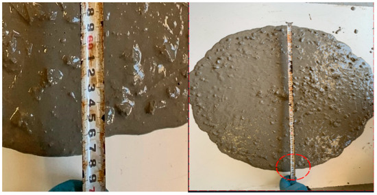
Figure 4.
Slump flow diameter for SCGC reinforced with 1.5% dosage of hybrid BFs.
Mixes represent single- and hybrid-length basalt-fibre-reinforced SCGC composites. The acronyms BF and HBF mean single and hybrid basalt fibre mixes, respectively. Furthermore, 12 and 30 indicate the used basalt fibre length, and 1, 1.5 and 2 are the BF dosage contents.
2.2. Test Setups and Procedures
2.2.1. Drying Shrinkage
Three prismatic beams with 75 mm × 75 mm × 280 mm dimensions were cast and prepared for each mixed composition, according to AS 1012.13-2015 Australian standards [53]. Steel nails were installed at the end of each prismatic beam to record specimen length change over time. As shown in Figure 5, the SCGC mixtures were poured into the drying shrinkage moulds. Afterwards, polythene plastic film was used to cover the specimens to reduce moisture evaporation. Samples were demolded after two days, and the first measurement was taken using comparator length, as shown in Figure 6. One side of the steel nails was placed on a sturdy metal base platform, and the other was positioned in a digital indicator with a precision of 0.001 mm. The Graff–Kaufman method was adopted in this study to measure the length variations of prismatic beams. The Graff–Kaufman method is relatively inexpensive, and the produced prismatic beams can be measured and stored for an extended period without occupying the measuring tool [55]. However, this method eliminates the measurements of early length changes in prismatic beams due to carbonation shrinkage [25]. Hence, in the current investigation, the overall measured shrinkage from the length comparator includes carbonation and drying shrinkage. The rate of carbonation shrinkage is affected by various parameters, including the curing process, mixture porosity, specimen size, temperature, relative humidity, CO2 concentration and length of exposure [25].
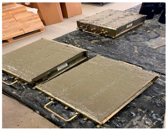
Figure 5.
Concrete shrinkage moulds.
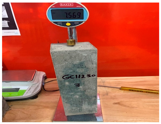
Figure 6.
Length comparator for measuring length changes.
After taking the first measurement, the specimens were placed in the environmental chamber, as shown in Figure 7, under 23 °C temperature and 49% relative humidity. The environmental chamber was used to keep all specimens at room temperature throughout the curing process. The change variations of sample lengths were high in the early days after demolding, so they were recorded daily. Over time, measurements were taken after more extended periods as fewer length variations were observed.
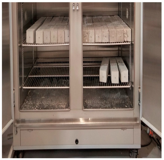
Figure 7.
Specimens to measure drying shrinkage were placed in the environmental chamber.
2.2.2. Plastic Shrinkage Cracking
The plastic shrinkage mould was manufactured using timber plywood following the ASTM C1579-06 standards [54]. As indicated in Figure 8, the mould dimensions are 560 mm (length) × 355 mm (width) × 100 mm (height). Two restraints of 32 ± 1 mm height were placed 90 ± 10 mm inward from both ends of the mould. A stress riser of 63.5 ± 1 mm was placed at the mould’s centre, as shown in Figure 8. According to ASTM C1579-06 standards [54], a minimum 1 kg/(h·m2) evaporation rate from the water surface is required to cause a crack. The standard test set a temperature, relative humidity, and wind speed of 36 ± 3 °C, 30 ± 10% and 4.7 m/s, respectively, to achieve the minimum required evaporation rate. However, a temperature of 55 °C and relative humidity of 20% was needed for a minimum evaporation rate of 1 kg/(h·m2). As shown in Figure 9, an environmental chamber was used to stimulate the required environmental conditions. The weight of each panel was measured on the scale and then placed on the bottom shelf of the humidity chamber, as shown in Figure 10a, to ensure continuous exposure to the uniformly circulated flowing air and, consequently, a higher evaporation rate from the concrete surface. Moulds to determine the final setting time were placed beside the panels in the humidity chamber. Figure 10b presents a schematic plan of the chamber contents.
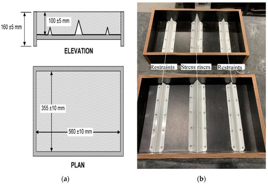
Figure 8.
The test set up for measuring plastic shrinkage cracking development. (a) Dimensions of plastic shrinkage moulds and (b) plastic shrinkage moulds (mm).
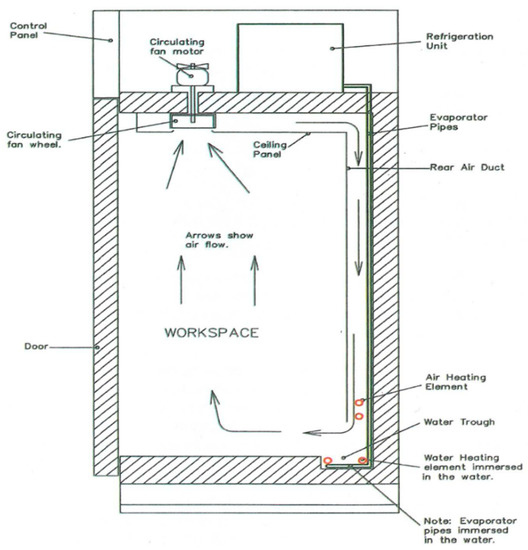
Figure 9.
The used environmental chamber was for the plastic shrinkage cracking test.
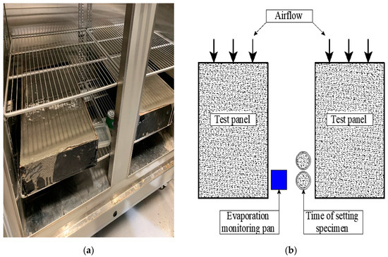
Figure 10.
Schematic plan of the chamber contents. (a) Specimens placed in an environmental chamber, (b) Environmental chamber schematic plan.
Monitoring the crack width for the developed mixtures during the first 24 h after casting was used to characterise the plastic shrinkage behaviour. Two measurement techniques were adopted to investigate the influence of BF lengths and dosages on the early-age cracking of SCGC, including a manual crack-measuring procedure using a crack width gauge (model CWG540) and image analysis. The crack width gauge is designed to measure the crack width to the nearest 0.01 mm. The crack widths were measured at six locations at 50 mm intervals along the length. Image analysis is an efficient and straightforward approach to quantifying the crack width and area. The images were taken with a high-resolution camera of 12 megapixels. Each pixel exhibits a greyscale value that varies between 0 and 255 based on the amount of light reflected by the concrete’s surface. During the test, images were captured every 30 min from the first crack sign at the concrete surface above the stress riser. Two LED work lights shone on the specimen’s concrete surface to improve the image’s luminosity. The captured images were converted to a thresholded binary image to measure the cracks, widths and areas. After the final setting time occurred for panels, the time was recorded, and the weight of the panels was measured. Afterwards, the panels were covered by a plastic sheet and placed in the environmental chamber at 23 °C. It aimed to reduce the moisture loss until the crack width was measured (24 h after casting). Notably, according to the research studies [56,57], a minimal change in crack widths from 6 to 24 h after casting is observed when panels are covered with plastic sheets.
3. Results and Discussions
3.1. Drying Shrinkage
The drying shrinkage rates of self-compacted geopolymer concrete and reinforced developed mixtures were assessed over 52 days. The measurements of the drying shrinkage rates of the prismatic beams ceased when length changes were almost stabilised. Figure 11 presents the obtained average results of the three prismatic beams. For most developed mixes, higher drying shrinkage rates were observed in the first ten days—up to 60% of the overall recorded drying shrinkage during the 52 days. However, lower drying shrinkage rates were observed for specimens incorporated with BFs than plain SCGC.
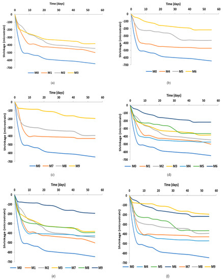
Figure 11.
Drying shrinkage rate for SCGC: (a) SCGC with 12 mm BFs; (b) SCGC with 30 mm BFs; (c) SCGC with hybrid-length BFs; (d) SCGC with 12 mm and 30 mm BFs; (e) SCGC with 12 mm and hybrid BFs; (f) SCGC with 30 mm and hybrid BFs.
Abdalhmid et al. 2019 [58] reported a drying shrinkage strain of 500 microstrains for self-compacted cementitious concrete at 52 days of age. This study recorded a drying shrinkage strain of 627 microstrains for SCGC at 52 days of age. According to the study findings, self-compacted geopolymer concrete has a 25% higher drying shrinkage rate than self-compacted cementitious concrete. However, Deb et al. [59] concluded that geopolymer composite made of fly ash and slag and cured at room temperature has an 11% lower drying shrinkage rate than cementitious composite at 28 days of age. Even so, several scholars claimed that fly ash and slag geopolymer composites cured at room temperatures have higher drying shrinkage rates than cementitious mixtures [25,60,61]. A high drying shrinkage rate in a geopolymer mixture is attributed to the water not fully integrating into the formation of a geopolymer matrix. Unlike composites made of cement, an amount of water remains interstitial within the composite structure. As a result, higher drying shrinkage rates in geopolymer composites are expected as the unbounded water during the chemical reaction is at an increased exposure of evaporation under ambient temperature and relative humidity conditions [25].
Slag-based geopolymer composite has the highest drying shrinkage amongst alkali-activated composites, almost three times higher than cementitious composite [19]. It has been hypothesised that the high drying shrinkage in slag-based composites results from the lack of crystal phases such as CH in the geopolymer structure [62]. Sherwani et al. (2022) [63] reported a higher drying shrinkage of SCGC made of fly ash and slag compared to SCGC made of 100% fly ash because of fly ash’s lower reactivity compared to a slag binder.
Moreover, 12 mm and 30 mm basalt fibres with 1%, 1.5% and 2% dosages were used to investigate their impact on managing SCGC’s drying shrinkage rate. For the reinforced SCGC with 12 mm length BFs, the maximum reduction of the drying shrinkage rate was 40% for the mix reinforced with 2%. SCGC reinforced with 12 mm length BFs and dosages of 1%, 1.5%, and 2% showed 10.4%, 31% and 40%, respectively, lower drying shrinkage rates than plain SCGC, as shown in Figure 11a. SCGC incorporated with 30 mm length BFs and dosages of 1%, 1.5% and 2% showed 27.1%, 43.7% and 66.3%, respectively, lower drying shrinkage rates than plain SCGC, as shown in Figure 11b. The increased dosage of BFs of up to 2% in SCGC consistently decreased the drying shrinkage rate due to the high absorption property of BFs. As shown in Figure 11d, the increase in BF length from 12 mm to 30 mm resulted in a higher decrease in the maximum drying shrinkage rate of reinforced SCGC compared to mixes reinforced with 12 mm BFs, the results of which are 18.8% (1% BFs), 18.3% (1.5% BFs) and 43% (2% BFs), respectively. Interestingly, mixes incorporated with long BFs showed better performance in limiting the drying shrinkage rate than short BFs, which may highlight the superior bridging action that long BFs have over short BFs. Long BFs performed better than short BFs in reducing the maximum drying shrinkage rates by restraining the propagation of early-age cracks due to plastic and drying shrinkage, resulting in better water retention within the geopolymer matrix.
SCGC mixes incorporated with hybrid short/long BFs better controlled the drying shrinkage rate than plain SCGC and 12 mm BF-reinforced SCGC, as shown in Figure 11c,e. M7, M8 and M9 showed 33.6%, 39% and 70% lower drying shrinkage rates than plain SCGC, as shown in Figure 11c. Compared to 12 mm BF-reinforced SCGC, M7, M8, and M9 showed 26%, 11.5% and 49.5% lower drying shrinkage rates than M1, M2 and M3, respectively (Figure 11e). Interestingly, SCGC incorporated with hybrid short/long BFs showed relatively similar maximum drying shrinkage rates to the maximum drying shrinkage rates of 30 mm BF-reinforced SCGC, as shown in Figure 11f. Although SCGC incorporated with hybrid short/long BFs demonstrated slightly better mechanical properties than mono-reinforced SCGC [1], the drying shrinkage results of the hybrid BF-reinforced mixes are within 10% of the SCGC mono-reinforced with 30 mm BFs for the same BF dosage. The results indicate that BF-length hybridisation has no significant effect on reducing the drying shrinkage rates compared to SCGC mono-reinforced with 30 mm BFs. The maximum drying shrinkage rates against BFs dosages are shown in Figure 12 for three sets of BFs with 12 mm, 30 mm and hybrid lengths. Figure 12 presents the maximum drying shrinkage rates for all developed mixes at 52 days of age. According to the findings, the optimum obtained drying shrinkage rate is 188 microstrains for SCGC reinforced with hybrid-length BFs and a dosage of 2%.
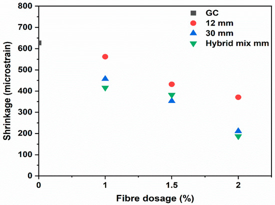
Figure 12.
Maximum drying shrinkage rates of developed mixes against BFs dosages.
3.2. Plastic Shrinkage Cracking
The plastic shrinkage cracking test was commenced directly 20 min after casting, and the final setting time occurred approximately 6 h after casting for all panels. The evaporation rate from the pan of water was measured every 30 min until the mix’s last setting time, and the evaporation rate was above 1 kg/m2, which complies with test requirements set by ASTM C1579-06 [54]. Plastic shrinkage cracking widths were manually measured using a crack width gauge and image analysis by ImageJ 1.51 software. Furthermore, 24 h after the casting time, images were taken, as shown in Figure 13, to analyse the cracks’ widths and areas. Figure 13a,b present the panel surface cracks of SCGC and SCGC reinforced with 1% of 12 mm BFs, respectively. The crack widths were measured at 50 mm intervals along the path, and the average value was reported. Figure 14 presents additional images of measured crack widths using a crack width gauge. In plain SCGC panels, the early-age cracks began to appear 3.5 h from the start time of the test and developed into macro-cracks in 30 min. The average crack width for SCGC panels 6 h and 24 h after casting is 0.5 mm and 0.87 mm, respectively. SCGC incorporated with a 1% dosage of 12 mm BFs showed a longer required 4 h for the first crack appearance. The average crack width for SCGC panels reinforced with 1% of 12 mm BFs 6 h and 24 h after casting is 0.22 mm and 0.32 mm, respectively.
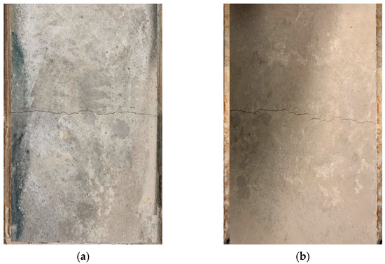
Figure 13.
Typical surface cracking in (a) M0 and (b) M1.
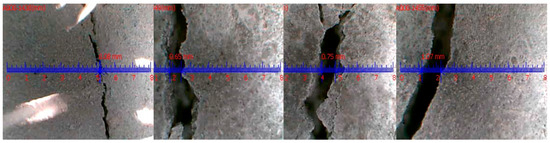
Figure 14.
Crack widths are measured using a crack width gauge.
On the other hand, in the first 24 h after casting, no macro-cracks could be observed in mixes reinforced with 30 mm, 12 mm (1.5 and 2% dosages) and hybrid-length BFs. The existence of BFs within the SCGC mix resulted in generating bridging forces above the stress risers that consequently prevented crack propagation. Additionally, including BFs reduces the amount of bleeding water and further increases the stiffness of SCGC at an early stage.
Studies [64,65,66,67] have reported that using long fibres showed a smaller concentration of localised strains above the stress riser than short fibres. It might be due to the increased area filled by the long fibres, which causes stress redistribution and, as a result, a drop in maximum strain values [64]. Longer fibres provide an adequate stress distribution and decrease stress concentration throughout the crack path [64,66,67]. The study results agree with previous studies as no macro-cracks were observed in SCGC panels reinforced with a 1% dosage of 30 mm BFs, compared to an average crack width of 0.32 mm recorded in SCGC panels reinforced with a 1% dosage of 12 mm BFs.
In addition to the manual measurement of cracks, image analysis was used to validate the accuracy of the obtained manual crack width measurements. The width of the crack was measured at multiple locations (usually at six locations, as shown in Figure 15) throughout the whole crack length. Figure 16 presents the crack width propagation measured using a crack width gauge (manual) and image analysis for SCGC and SCGC reinforced with a 1% dosage of 12 mm BFs. The results show that both image analysis and manual measurement results are in good agreement, as variations in crack width between the two methods are less than 5%. Based on the image analysis results, using a 1% dosage of 12 mm BFs in SCGC reduces crack area by approximately 60% compared to plain SCGC.
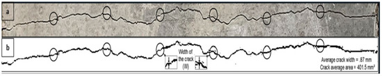
Figure 15.
The image analysis technique was used to measure the average crack width and area of SCGC. (a) original greyscale image, (b) binary image.
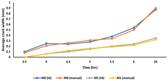
Figure 16.
Cracks width measurement until the test’s end using image analysis (IA) and crack width gauge (manual).
Few studies have reported no noticeable difference in average crack width when cementitious concrete panels are covered with plastic sheets from 6 to 24 h after starting the test [54,56]. However, a 42% increase in crack width was observed after 24 h compared to the crack width at 6 h. On the other hand, for SCGC panels reinforced with a 1% dosage of 12 mm BFs, a 31% increase in crack width was observed after 24 h compared to the crack width at 6 h after casting. The rise in crack width between 6 and 24 h returns to the evaporation of unbounded water during the chemical reaction. Unlike composites made of cement, water does not fully integrate into the formation of a geopolymer matrix. Incorporating a 1% dosage of 12 mm BFs into SCGC results in 26% less crack propagation than plain SCGC panels. A crack reduction ratio (CRR) of 62.87% was developed for the SCGC mix reinforced with a 1% dosage of 12 mm BFs.
Moreover, 2.49% of moisture loss was observed in the SCGC mix 24 h after casting. The increase in BF dosage up to 2% in SCGC resulted in the reduction of moisture loss, as shown in Figure 17. However, long fibres performed better in retaining water within the SCGC structure than short fibres. BF-length hybridisation shows no significant impact on reducing moisture loss compared to the effect of the long fibres.
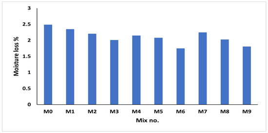
Figure 17.
Moisture loss of developed mixes.
4. Conclusions
This study reports the experimental findings of a comparative investigation on the impacts of 12 mm, 30 mm and hybrid-length basalt fibres on the drying shrinkage rate and early-age plastic shrinkage cracking of self-compacted geopolymer concrete. A total of 30 specimens and 20 panels were employed in the experimental investigation to determine the drying shrinkage rates and study plastic shrinkage cracking, respectively. The following findings can be drawn from the conducted research:
- SCGC has a drying shrinkage rate of 627 microstrains, 25% higher than self-compacted cementitious concrete.
- The addition of up to a 2% dosage of both short and long basalt fibres to SCGC results in the reduction of the drying shrinkage rate. The lowest observed drying shrinkage rate is 188 microstrains for SCGC reinforced with a 2% dosage of hybrid-length BFs.
- Using 1% to 2% of BFs in the SCGC mix reduces the early-age crack width due to plastic shrinkage. Adding a 1% dosage of 12 mm BFs reduces the crack width from 0.87 mm (average crack width in SCGC panels) to an average crack width of 0.32 mm.
- No early-age macro-cracks were observed in mixes reinforced with 30 mm, 12 mm (1.5 and 2% dosages) and hybrid-length BFs.
- The results obtained for average crack width from two measurement methods—crack width gauge (manual) and image analysis—are in the cooperative agreement, as variations in crack width between the two methods are less than 5%.
- Long fibres were more efficient at reducing drying shrinkage rates and controlling early-age cracks than short fibres.
- Using a hybrid length of short/long BFs in SCGC to reduce drying shrinkage rates shows close results to long BFs with the exact BF dosage. It indicates no significant effect of BF-length hybridisation on reducing drying shrinkage compared to long BFs. However, combining hybrid short/long BFs showed better results in lowering drying shrinkage rates in SCGC than short BFs.
Author Contributions
Conceptualisation, M.H. and R.A.-A.; Data curation, M.H.; Investigation, M.H.; Methodology, M.H.; Supervision, B.K. and R.A.-A.; Writing—original draft, M.H.; Writing—review and editing, M.H., B.K. and R.A.-A. All authors have read and agreed to the published version of the manuscript.
Funding
This research received no external funding.
Institutional Review Board Statement
Not applicable.
Informed Consent Statement
Not applicable.
Data Availability Statement
Available on request from authors.
Acknowledgments
The authors would like to acknowledge the support of Deakin University in carrying out the present study. Moreover, the assistance of Leanne Farago, Lube Veljanoski and Michael Shanahan during the experimental phase of the study is gratefully acknowledged.
Conflicts of Interest
The authors declare no conflict of interest.
References
- Heweidak, M.; Kafle, B.; Al-Ameri, R. Influence of Hybrid Basalt Fibres Length on Fresh and Mechanical Properties of Self-Compacted Ambient-Cured Geopolymer Concrete. J. Compos. Sci. 2022, 6, 292. [Google Scholar] [CrossRef]
- Ofosu-Adarkwa, J.; Xie, N.; Javed, S.A. Forecasting CO2 emissions of China’s cement industry using a hybrid Verhulst-GM (1, N) model and emissions’ technical conversion. Renew. Sustain. Energy Rev. 2020, 130, 109945. [Google Scholar] [CrossRef]
- International Energy Agency. Cement Technology Roadmap Plots Path to Cutting CO2 Emissions 24% by 2050; News; IEA: Paris, France, 2018; pp. 1–3. [Google Scholar]
- Heweidak, M.; Kafle, B.; Al-Ameri, R. Shear-Bond Behaviour of Profiled Composite Slab Incorporated with Self-Compacted Geopolymer Concrete. Appl. Sci. 2022, 12, 8512. [Google Scholar] [CrossRef]
- Heweidak, M.; Kafle, B.; Al-Ameri, R. Effect of Discrete Basalt Fibres Length on Fresh And Mechanical Properties of Self-Compacted Geopolymer Concrete. In Proceedings of the 3rd International Conference on Structural Engineering Research (iCSER 2022), Sydney, Australia, 27–30 November 2022; p. 11. [Google Scholar]
- Davidovits, J.; Cordi, S. Synthesis of New High Temperature Geo-Polymers for Reinforced Plastics/Composites; SPE PACTEC′79; Society of Plastics Engineers: Brookfield, WI, USA, 1979; pp. 151–154. [Google Scholar]
- Ma, C.-K.; Awang, A.Z.; Omar, W. Structural and material performance of geopolymer concrete: A review. Constr. Build. Mater. 2018, 186, 90–102. [Google Scholar] [CrossRef]
- Timakul, P.; Rattanaprasit, W.; Aungkavattana, P. Improving compressive strength of fly ash-based geopolymer composites by basalt fibers addition. Ceram. Int. 2016, 42, 6288–6295. [Google Scholar] [CrossRef]
- Nath, P.; Sarker, P.K. Flexural strength and elastic modulus of ambient-cured blended low-calcium fly ash geopolymer concrete. Constr. Build. Mater. 2017, 130, 22–31. [Google Scholar] [CrossRef]
- Rahman, S.K.; Al-Ameri, R. A newly developed self-compacting geopolymer concrete under ambient condition. Constr. Build. Mater. 2021, 267, 121822. [Google Scholar] [CrossRef]
- Sarker, P.K. Bond strength of reinforcing steel embedded in fly ash-based geopolymer concrete. Mater. Struct. 2011, 44, 1021–1030. [Google Scholar] [CrossRef]
- Castel, A.; Foster, S.J. Bond strength between blended slag and Class F fly ash geopolymer concrete with steel reinforcement. Cem. Concr. Res. 2015, 72, 48–53. [Google Scholar] [CrossRef]
- Luhar, S.; Nicolaides, D.; Luhar, I. Fire resistance behaviour of geopolymer concrete: An overview. Buildings 2021, 11, 82. [Google Scholar] [CrossRef]
- Ariffin, M.; Bhutta, M.; Hussin, M.; Tahir, M.M.; Aziah, N. Sulfuric acid resistance of blended ash geopolymer concrete. Constr. Build. Mater. 2013, 43, 80–86. [Google Scholar] [CrossRef]
- Zhao, R.; Yuan, Y.; Cheng, Z.; Wen, T.; Li, J.; Li, F.; Ma, Z.J. Freeze-thaw resistance of Class F fly ash-based geopolymer concrete. Constr. Build. Mater. 2019, 222, 474–483. [Google Scholar] [CrossRef]
- Fan, Y.; Yin, S.; Wen, Z.; Zhong, J. Activation of fly ash and its effects on cement properties. Cem. Concr. Res. 1999, 29, 467–472. [Google Scholar] [CrossRef]
- Puertas, F.; Martínez-Ramírez, S.; Alonso, S.; Vázquez, T. Alkali-activated fly ash/slag cements: Strength behaviour and hydration products. Cem. Concr. Res. 2000, 30, 1625–1632. [Google Scholar] [CrossRef]
- Somna, K.; Jaturapitakkul, C.; Kajitvichyanukul, P.; Chindaprasirt, P. NaOH-activated ground fly ash geopolymer cured at ambient temperature. Fuel 2011, 90, 2118–2124. [Google Scholar] [CrossRef]
- Mastali, M.; Kinnunen, P.; Dalvand, A.; Firouz, R.M.; Illikainen, M. Drying shrinkage in alkali-activated binders—A critical review. Constr. Build. Mater. 2018, 190, 533–550. [Google Scholar] [CrossRef]
- Lee, N.K.; Lee, H.K. Setting and mechanical properties of alkali-activated fly ash/slag concrete manufactured at room temperature. Constr. Build. Mater. 2013, 47, 1201–1209. [Google Scholar] [CrossRef]
- Yao, X.; Yang, T.; Zhang, Z. Compressive strength development and shrinkage of alkali-activated fly ash–slag blends associated with efflorescence. Mater. Struct. 2016, 49, 2907–2918. [Google Scholar] [CrossRef]
- Marjanović, N.; Komljenović, M.; Baščarević, Z.; Nikolić, V.; Petrović, R. Physical–mechanical and microstructural properties of alkali-activated fly ash–blast furnace slag blends. Ceram. Int. 2015, 41, 1421–1435. [Google Scholar] [CrossRef]
- Kheradmand, M.; Abdollahnejad, Z.; Pacheco-Torgal, F. Drying shrinkage of fly ash geopolymeric mortars reinforced with polymer hybrid fibres. Proc. Inst. Civ. Eng. Constr. Mater. 2020, 173, 28–40. [Google Scholar] [CrossRef]
- Ranjbar, N.; Talebian, S.; Mehrali, M.; Kuenzel, C.; Cornelis Metselaar, H.S.; Jumaat, M.Z. Mechanisms of interfacial bond in steel and polypropylene fiber reinforced geopolymer composites. Compos. Sci. Technol. 2016, 122, 73–81. [Google Scholar] [CrossRef]
- Abdollahnejad, Z.; Mastali, M.; Mastali, M.; Dalvand, A. Comparative study on the effects of recycled glass–fiber on drying shrinkage rate and mechanical properties of the self-compacting mortar and fly ash–slag geopolymer mortar. J. Mater. Civ. Eng. 2017, 29, 04017076. [Google Scholar] [CrossRef]
- Gao, X.; Yu, Q.L.; Yu, R.; Brouwers, H.J.H. Evaluation of hybrid steel fiber reinforcement in high performance geopolymer composites. Mater. Struct. 2017, 50, 165. [Google Scholar] [CrossRef]
- Zhang, Z.-H.; Yao, X.; Zhu, H.-J.; Hua, S.-D.; Chen, Y. Preparation and mechanical properties of polypropylene fiber reinforced calcined kaolin-fly ash based geopolymer. J. Cent. South Univ. Technol. 2009, 16, 49–52. [Google Scholar] [CrossRef]
- Hanjitsuwan, S.; Injorhor, B.; Phoo-ngernkham, T.; Damrongwiriyanupap, N.; Li, L.-Y.; Sukontasukkul, P.; Chindaprasirt, P. Drying shrinkage, strength and microstructure of alkali-activated high-calcium fly ash using FGD-gypsum and dolomite as expansive additive. Cem. Concr. Compos. 2020, 114, 103760. [Google Scholar] [CrossRef]
- Rezende Schuab, M.; José dos Santos, W.; Henrique Ribeiro Borges, P. On the development of MK/BFS alkali-activated materials as repair mortars: Performance under free and restrained shrinkage tests. Constr. Build. Mater. 2021, 275, 122109. [Google Scholar] [CrossRef]
- Abdollahnejad, Z.; Mastali, M.; Luukkonen, T.; Kinnunen, P.; Illikainen, M. Fiber-reinforced one-part alkali-activated slag/ceramic binders. Ceram. Int. 2018, 44, 8963–8976. [Google Scholar] [CrossRef]
- Sim, J.; Park, C. Characteristics of basalt fiber as a strengthening material for concrete structures. Compos. Part B Eng. 2005, 36, 504–512. [Google Scholar] [CrossRef]
- Adesina, A. Performance of cementitious composites reinforced with chopped basalt fibres—An overview. Constr. Build. Mater. 2021, 266, 120970. [Google Scholar] [CrossRef]
- Kogan, F.; Nikitina, O. Solubility of chrysotile asbestos and basalt fibers in relation to their fibrogenic and carcinogenic action. Environ. Health Perspect. 1994, 102, 205–206. [Google Scholar]
- Fiore, V.; Scalici, T.; Di Bella, G.; Valenza, A. A review on basalt fibre and its composites. Compos. Part B Eng. 2015, 74, 74–94. [Google Scholar] [CrossRef]
- Luo, X.; Xu, J.-y.; Bai, E.-l.; Li, W. Study on the effect of basalt fiber on the energy absorption characteristics of porous material. Constr. Build. Mater. 2014, 68, 384–390. [Google Scholar] [CrossRef]
- Xin, L.; Jin-Yu, X.; Weimin, L.; Zhi-Kun, W. Comparative Study of the Effect of Basalt Fiber on Dynamic Damage Characteristics of Ceramics Cement–Based Porous Material. J. Mater. Civ. Eng. 2015, 27, 04014224. [Google Scholar] [CrossRef]
- Bheel, N. Basalt fibre-reinforced concrete: Review of fresh and mechanical properties. J. Build. Pathol. Rehabil. 2021, 6, 12. [Google Scholar] [CrossRef]
- Deák, T.; Czigány, T. Chemical composition and mechanical properties of basalt and glass fibers: A comparison. Text. Res. J. 2009, 79, 645–651. [Google Scholar] [CrossRef]
- Scheffler, C.; Förster, T.; Mäder, E.; Heinrich, G.; Hempel, S.; Mechtcherine, V. Aging of alkali-resistant glass and basalt fibers in alkaline solutions: Evaluation of the failure stress by Weibull distribution function. J. Non-Cryst. Solids 2009, 355, 2588–2595. [Google Scholar] [CrossRef]
- Wei, B.; Cao, H.; Song, S. Tensile behavior contrast of basalt and glass fibers after chemical treatment. Mater. Des. 2010, 31, 4244–4250. [Google Scholar] [CrossRef]
- Zhu, L.; Sun, B.; Gu, B. Frequency features of basalt filament tows under quasi-static and high strain rate tension. J. Compos. Mater. 2012, 46, 1285–1293. [Google Scholar] [CrossRef]
- Punurai, W.; Kroehong, W.; Saptamongkol, A.; Chindaprasirt, P. Mechanical properties, microstructure and drying shrinkage of hybrid fly ash-basalt fiber geopolymer paste. Constr. Build. Mater. 2018, 186, 62–70. [Google Scholar] [CrossRef]
- Saloni; Parveen; Pham, T.M. Enhanced properties of high-silica rice husk ash-based geopolymer paste by incorporating basalt fibers. Constr. Build. Mater. 2020, 245, 118422. [Google Scholar] [CrossRef]
- Xu, J.; Kang, A.; Wu, Z.; Xiao, P.; Gong, Y. Effect of high-calcium basalt fiber on the workability, mechanical properties and microstructure of slag-fly ash geopolymer grouting material. Constr. Build. Mater. 2021, 302, 124089. [Google Scholar] [CrossRef]
- AS/NZS 3582.1:2016; Supplementary Cementitious Materials Fly Ash. Standards New Zealand: Wellington, New Zealand, 2016; 11p. Available online: https://infostore.saiglobal.com/en-us/standards/as-nzs-3582-1-2016-101026_saig_as_as_212259/ (accessed on 15 January 2023).
- Zhang, J.; Tan, H.; Bao, M.; Liu, X.; Luo, Z.; Wang, P. Low carbon cementitious materials: Sodium sulfate activated ultra-fine slag/fly ash blends at ambient temperature. J. Clean. Prod. 2021, 280, 124363. [Google Scholar] [CrossRef]
- Krishnaraj, L.; Ravichandran, P.T. Characterisation of ultra-fine fly ash as sustainable cementitious material for masonry construction. Ain Shams Eng. J. 2021, 12, 259–269. [Google Scholar] [CrossRef]
- Banibayat, P.; Patnaik, A. Variability of mechanical properties of basalt fiber reinforced polymer bars manufactured by wet-layup method. Mater. Des. 2014, 56, 898–906. [Google Scholar] [CrossRef]
- Masi, G.; Rickard, W.D.A.; Bignozzi, M.C.; van Riessen, A. The effect of organic and inorganic fibres on the mechanical and thermal properties of aluminate activated geopolymers. Compos. Part B Eng. 2015, 76, 218–228. [Google Scholar] [CrossRef]
- Dias, D.P.; Thaumaturgo, C. Fracture toughness of geopolymeric concretes reinforced with basalt fibers. Cem. Concr. Compos. 2005, 27, 49–54. [Google Scholar] [CrossRef]
- Hassani Niaki, M.; Fereidoon, A.; Ghorbanzadeh Ahangari, M. Experimental study on the mechanical and thermal properties of basalt fiber and nanoclay reinforced polymer concrete. Compos. Struct. 2018, 191, 231–238. [Google Scholar] [CrossRef]
- AS 1012.3.1:2014; Methods of Testing Concrete Determination of Properties Related to the Consistency of Concrete—Slump Flow, T500 and J-Ring Test. Standards Australia: Sydney, NSW, Australia, 2015; p. 9. Available online: https://infostore.saiglobal.com/en-us/standards/as-1012-3-5-2015-111337_saig_as_as_232905/ (accessed on 14 August 2022).
- AS 1012.13-2015; Methods of Testing Concrete; Method 13: Determination of the Drying Shrinkage of Concrete for Samples Prepared in the Field or in the Laboratory. Standards Australia: Sydney, NSW, Australia, 2015.
- ASTM C1579-06; Standard Test Method for Evaluating Plastic Shrinkage Cracking of Restrained Fiber Reinforced Concrete (Using a Steel form Insert). American Society for Testing and Materials: West Conshohocken, PA, USA, 2021; 7p.
- Lenart, M.; Gruszczyński, M. The research of mortars shrinkage made with reclaimed aggregate. Procedia Struct. Integr. 2019, 23, 113–118. [Google Scholar] [CrossRef]
- Qi, C.; Weiss, J.; Olek, J. Statistical significance of the restrained slab test for quantifying plastic cracking in fiber reinforced concrete. J. ASTM Int. 2005, 2, JAI12242. [Google Scholar]
- Hemalatha, T.; Ramesh, G. Mitigation of plastic shrinkage in fly ash concrete using basalt fibres. Can. J. Civ. Eng. 2019, 46, 759–769. [Google Scholar] [CrossRef]
- Abdalhmid, J.M.; Ashour, A.F.; Sheehan, T. Long-term drying shrinkage of self-compacting concrete: Experimental and analytical investigations. Constr. Build. Mater. 2019, 202, 825–837. [Google Scholar] [CrossRef]
- Deb, P.S.; Nath, P.; Sarker, P.K. Drying shrinkage of slag blended fly ash geopolymer concrete cured at room temperature. Procedia Eng. 2015, 125, 594–600. [Google Scholar] [CrossRef]
- Chi, M. Effects of modulus ratio and dosage of alkali-activated solution on the properties and micro-structural characteristics of alkali-activated fly ash mortars. Constr. Build. Mater. 2015, 99, 128–136. [Google Scholar] [CrossRef]
- Ye, H.; Cartwright, C.; Rajabipour, F.; Radlińska, A. Effect of drying rate on shrinkage of alkali-activated slag cements. In Proceedings of the 4th ICDCS, West Lafayette, IN, USA, 24–26 July 2014. [Google Scholar]
- Aydın, S.; Baradan, B. Mechanical and microstructural properties of heat cured alkali-activated slag mortars. Mater. Des. 2012, 35, 374–383. [Google Scholar] [CrossRef]
- Sherwani, A.F.H.; Younis, K.H.; Arndt, R.W.; Pilakoutas, K. Performance of Self-Compacted Geopolymer Concrete Containing Fly Ash and Slag as Binders. Sustainability 2022, 14, 15063. [Google Scholar] [CrossRef]
- Kouta, N.; Saliba, J.; Saiyouri, N. Effect of flax fibers on early age shrinkage and cracking of earth concrete. Constr. Build. Mater. 2020, 254, 119315. [Google Scholar] [CrossRef]
- Bertelsen, I.M.G.; Ottosen, L.M.; Fischer, G. Influence of fibre characteristics on plastic shrinkage cracking in cement-based materials: A review. Constr. Build. Mater. 2020, 230, 116769. [Google Scholar] [CrossRef]
- Banthia, N.; Gupta, R. Influence of polypropylene fiber geometry on plastic shrinkage cracking in concrete. Cem. Concr. Res. 2006, 36, 1263–1267. [Google Scholar] [CrossRef]
- Borg, R.P.; Baldacchino, O.; Ferrara, L. Early age performance and mechanical characteristics of recycled PET fibre reinforced concrete. Constr. Build. Mater. 2016, 108, 29–47. [Google Scholar] [CrossRef]
Disclaimer/Publisher’s Note: The statements, opinions and data contained in all publications are solely those of the individual author(s) and contributor(s) and not of MDPI and/or the editor(s). MDPI and/or the editor(s) disclaim responsibility for any injury to people or property resulting from any ideas, methods, instructions or products referred to in the content. |
© 2023 by the authors. Licensee MDPI, Basel, Switzerland. This article is an open access article distributed under the terms and conditions of the Creative Commons Attribution (CC BY) license (https://creativecommons.org/licenses/by/4.0/).