
Effect of Nanoparticles and Their Anisometry on Adhesion and Strength in Hybrid Carbon-Fiber-Reinforced Epoxy Nanocomposites


Abstract
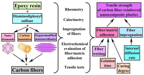
1. Introduction
2. Materials and Methods
2.1. Materials
2.2. Standard Methods
2.3. Electrochemical Method for Assessing Adhesion between Carbon Fibers and a Polymer Matrix
2.3.1. The Base of the Method
2.3.2. Calibration of the Method
3. Results and Discussion
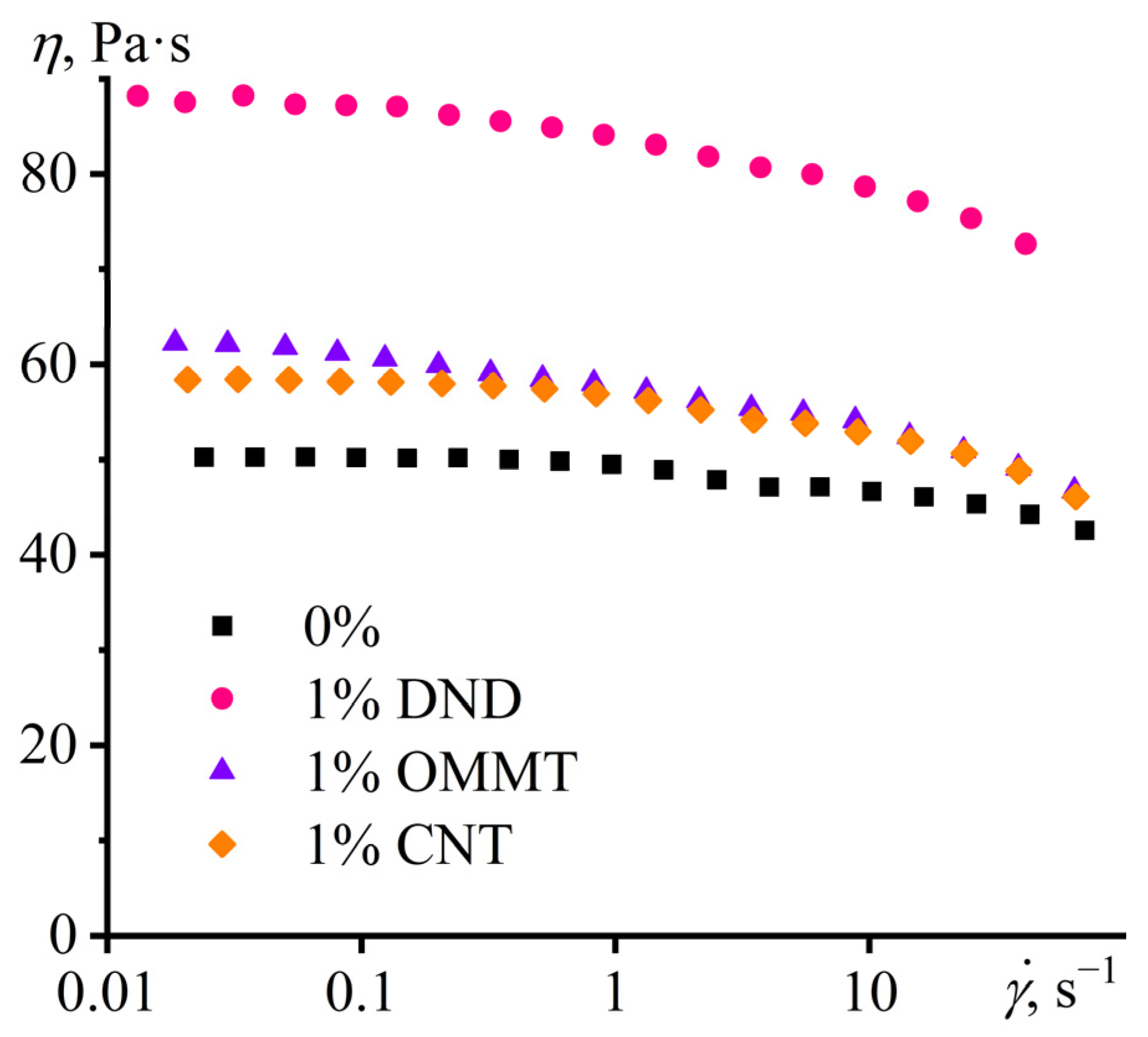
3.1. Properties of Nanoparticle Dispersions in Epoxy Resin
3.2. Effect of Nanoparticles on the Curing of Epoxy Binder
3.3. Effect of Nanoparticles on the Impregnation of Carbon Fibers with Epoxy Binder
3.4. Adhesion and Strength in the Carbon Fiber–Epoxy Nanocomposite Matrix System
3.5. Glass Transition in Cured Composites
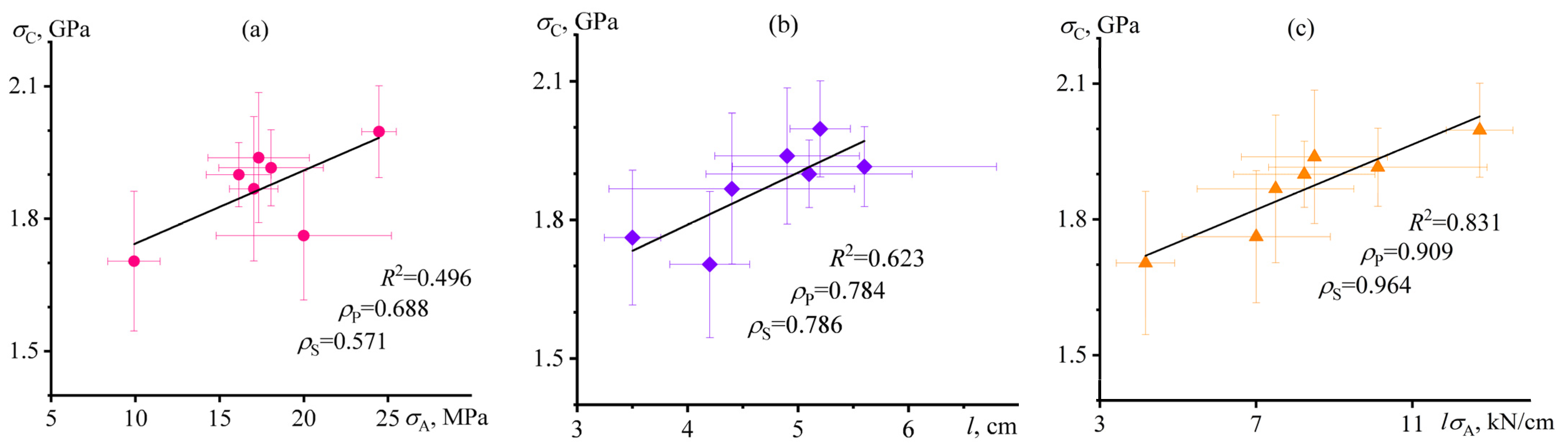
3.6. Mutual Correlations of Characteristics of Carbon-Fiber-Reinforced Nanocomposite Plastics
4. Conclusions
- The measurement of electrical conduction of fractured carbon single-bundle plastics allows for evaluating the adhesion between the carbon fiber and the dielectric polymer matrix, which correlates with plastics’ tensile strength.
- Nanoparticles can increase the tensile strength of carbon-fiber-reinforced plastics by improving the impregnation of the carbon fiber with the binder and enhancing fiber–matrix adhesion, which may be due to improved fiber wetting with the nanocomposite binder, accelerated internal diffusion of binder molecules by nanoparticles, slowing the cross-linking of the binder, and increasing the curing degree.
- For improving the tensile strength of fiber-reinforced plastics, the concentration of nanoparticles should be low to avoid increased binder viscosity and deterioration of fiber impregnation. Moreover, isometric particles are more effective than anisometric nanotubes and nanoplates, possibly due to easier adsorption on the surface of carbon fibers.
- The maximum strengthening effect results from filling the epoxy binder with 0.1% detonation nanodiamonds, which increase the fiber–matrix adhesion and plastic’s tensile strength by 150% and 17%, respectively, creating novel hybrid carbon-fiber-reinforced epoxy nanocomposite with higher performance.
Author Contributions
Funding
Data Availability Statement
Acknowledgments
Conflicts of Interest
References
- Müller, K.; Bugnicourt, E.; Latorre, M.; Jorda, M.; Echegoyen Sanz, Y.; Lagaron, J.; Miesbauer, O.; Bianchin, A.; Hankin, S.; Bölz, U.; et al. Review on the Processing and Properties of Polymer Nanocomposites and Nanocoatings and Their Applications in the Packaging, Automotive and Solar Energy Fields. Nanomaterials 2017, 7, 74. [Google Scholar] [CrossRef] [PubMed]
- Sharma, S.; Sudhakara, P.; Omran, A.A.B.; Singh, J.; Ilyas, R.A. Recent Trends and Developments in Conducting Polymer Nanocomposites for Multifunctional Applications. Polymers 2021, 13, 2898. [Google Scholar] [CrossRef]
- Agboola, O.; Fayomi, O.S.I.; Ayodeji, A.; Ayeni, A.O.; Alagbe, E.E.; Sanni, S.E.; Okoro, E.E.; Moropeng, L.; Sadiku, R.; Kupolati, K.W.; et al. A Review on Polymer Nanocomposites and Their Effective Applications in Membranes and Adsorbents for Water Treatment and Gas Separation. Membranes 2021, 11, 139. [Google Scholar] [CrossRef] [PubMed]
- Chan, J.X.; Wong, J.F.; Petrů, M.; Hassan, A.; Nirmal, U.; Othman, N.; Ilyas, R.A. Effect of Nanofillers on Tribological Properties of Polymer Nanocomposites: A Review on Recent Development. Polymers 2021, 13, 2867. [Google Scholar] [CrossRef]
- Fu, S.; Sun, Z.; Huang, P.; Li, Y.; Hu, N. Some Basic Aspects of Polymer Nanocomposites: A Critical Review. Nano Mater. Sci. 2019, 1, 2–30. [Google Scholar] [CrossRef]
- Kotal, M.; Bhowmick, A.K. Polymer Nanocomposites from Modified Clays: Recent Advances and Challenges. Prog. Polym. Sci. 2015, 51, 127–187. [Google Scholar] [CrossRef]
- Bee, S.-L.; Abdullah, M.A.A.; Bee, S.-T.; Sin, L.T.; Rahmat, A.R. Polymer Nanocomposites Based on Silylated-Montmorillonite: A Review. Prog. Polym. Sci. 2018, 85, 57–82. [Google Scholar] [CrossRef]
- Ebrahimi, F.; Qaderi, S. Stability Analysis of Embedded Graphene Platelets Reinforced Composite Plates in Thermal Environment. Eur. Phys. J. Plus 2019, 134, 349. [Google Scholar] [CrossRef]
- Sun, X.; Huang, C.; Wang, L.; Liang, L.; Cheng, Y.; Fei, W.; Li, Y. Recent Progress in Graphene/Polymer Nanocomposites. Adv. Mater. 2021, 33, 2001105. [Google Scholar] [CrossRef]
- Kumar, A.; Sharma, K.; Dixit, A.R. A Review of the Mechanical and Thermal Properties of Graphene and Its Hybrid Polymer Nanocomposites for Structural Applications. J. Mater. Sci. 2019, 54, 5992–6026. [Google Scholar] [CrossRef]
- Islam, M.H.; Afroj, S.; Uddin, M.A.; Andreeva, D.V.; Novoselov, K.S.; Karim, N. Graphene and CNT-Based Smart Fiber-Reinforced Composites: A Review. Adv. Funct. Mater. 2022, 32, 2205723. [Google Scholar] [CrossRef]
- Hallad, S.A.; Banapurmath, N.R.; Patil, V.; Ajarekar, V.S.; Patil, A.; Godi, M.T.; Shettar, A.S. Graphene Reinforced Natural Fiber Nanocomposites for Structural Applications. IOP Conf. Ser. Mater. Sci. Eng. 2018, 376, 012072. [Google Scholar] [CrossRef]
- Bhattacharya, M. Polymer Nanocomposites—A Comparison between Carbon Nanotubes, Graphene, and Clay as Nanofillers. Materials 2016, 9, 262. [Google Scholar] [CrossRef] [PubMed]
- Siwal, S.S.; Zhang, Q.; Devi, N.; Thakur, V.K. Carbon-Based Polymer Nanocomposite for High-Performance Energy Storage Applications. Polymers 2020, 12, 505. [Google Scholar] [CrossRef]
- Khan, F.S.A.; Mubarak, N.M.; Khalid, M.; Khan, M.M.; Tan, Y.H.; Walvekar, R.; Abdullah, E.C.; Karri, R.R.; Rahman, M.E. Comprehensive Review on Carbon Nanotubes Embedded in Different Metal and Polymer Matrix: Fabrications and Applications. Crit. Rev. Solid State Mater. Sci. 2022, 47, 837–864. [Google Scholar] [CrossRef]
- Ilyin, S.O.; Arinina, M.P.; Mamulat, Y.S.; Malkin, A.Y.; Kulichikhin, V.G. Rheological Properties of Road Bitumens Modified with Polymer and Solid Nanosized Additives. Colloid J. 2014, 76, 425–434. [Google Scholar] [CrossRef]
- Pan, D.; Luo, S.; Feng, Y.; Zhang, X.; Su, F.; Liu, H.; Liu, C.; Mai, X.; Naik, N.; Guo, Z. Highly Thermally Conductive 3D BN/MWCNTs/C Spatial Network Composites with Improved Electrically Insulating and Flame Retardancy Prepared by Biological Template Assisted Method. Compos. Part B Eng. 2021, 222, 109039. [Google Scholar] [CrossRef]
- Massaro, M.; Noto, R.; Riela, S. Past, Present and Future Perspectives on Halloysite Clay Minerals. Molecules 2020, 25, 4863. [Google Scholar] [CrossRef]
- Kargarzadeh, H.; Mariano, M.; Huang, J.; Lin, N.; Ahmad, I.; Dufresne, A.; Thomas, S. Recent Developments on Nanocellulose Reinforced Polymer Nanocomposites: A Review. Polymer 2017, 132, 368–393. [Google Scholar] [CrossRef]
- Ilyin, S.O.; Gorbacheva, S.N.; Yadykova, A.Y. Rheology and Tribology of Nanocellulose-Based Biodegradable Greases: Wear and Friction Protection Mechanisms of Cellulose Microfibrils. Tribol. Int. 2023, 178, 108080. [Google Scholar] [CrossRef]
- Kostyuk, A.; Ignatenko, V.; Smirnova, N.; Brantseva, T.; Ilyin, S.; Antonov, S. Rheology and Adhesive Properties of Filled PIB-Based Pressure-Sensitive Adhesives. I. Rheology and Shear Resistance. J. Adhes. Sci. Technol. 2015, 29, 1831–1848. [Google Scholar] [CrossRef]
- Gorbacheva, S.N.; Makarova, V.V.; Ilyin, S.O. Hydrophobic Nanosilica-Stabilized Graphite Particles for Improving Thermal Conductivity of Paraffin Wax-Based Phase-Change Materials. J. Energy Storage 2021, 36, 102417. [Google Scholar] [CrossRef]
- Pearce, A.K.; Wilks, T.R.; Arno, M.C.; O’Reilly, R.K. Synthesis and Applications of Anisotropic Nanoparticles with Precisely Defined Dimensions. Nat. Rev. Chem. 2020, 5, 21–45. [Google Scholar] [CrossRef]
- Kostyuk, A.V.; Ignatenko, V.Y.; Makarova, V.V.; Antonov, S.V.; Ilyin, S.O. Polyethylene Wax as an Alternative to Mineral Fillers for Preparation of Reinforced Pressure-Sensitive Adhesives. Int. J. Adhes. Adhes. 2020, 102, 102689. [Google Scholar] [CrossRef]
- Malkin, A.Y.; Ilyin, S.O.; Arinina, M.P.; Kulichikhin, V.G. The Rheological State of Suspensions in Varying the Surface Area of Nano-Silica Particles and Molecular Weight of the Poly(Ethylene Oxide) Matrix. Colloid Polym. Sci. 2017, 295, 555–563. [Google Scholar] [CrossRef]
- Shrestha, S.; Wang, B.; Dutta, P. Nanoparticle Processing: Understanding and Controlling Aggregation. Adv. Colloid Interface Sci. 2020, 279, 102162. [Google Scholar] [CrossRef]
- Ilyin, S.O.; Arinina, M.P.; Malkin, A.Y.; Kulichikhin, V.G. Sol–Gel Transition and Rheological Properties of Silica Nanoparticle Dispersions. Colloid J. 2016, 78, 608–615. [Google Scholar] [CrossRef]
- Gisbert-Garzarán, M.; Vallet-Regí, M. Influence of the Surface Functionalization on the Fate and Performance of Mesoporous Silica Nanoparticles. Nanomaterials 2020, 10, 916. [Google Scholar] [CrossRef]
- Brantseva, T.; Antonov, S.; Kostyuk, A.; Ignatenko, V.; Smirnova, N.; Korolev, Y.; Tereshin, A.; Ilyin, S. Rheological and Adhesive Properties of PIB-Based Pressure-Sensitive Adhesives with Montmorillonite-Type Nanofillers. Eur. Polym. J. 2016, 76, 228–244. [Google Scholar] [CrossRef]
- Yadykova, A.Y.; Ilyin, S.O. Rheological and Adhesive Properties of Nanocomposite Bitumen Binders Based on Hydrophilic or Hydrophobic Silica and Modified with Bio-Oil. Constr. Build. Mater. 2022, 342, 127946. [Google Scholar] [CrossRef]
- Yadykova, A.Y.; Ilyin, S.O. Bitumen Improvement with Bio-Oil and Natural or Organomodified Montmorillonite: Structure, Rheology, and Adhesion of Composite Asphalt Binders. Constr. Build. Mater. 2023, 364, 129919. [Google Scholar] [CrossRef]
- Nurazzi, N.M.; Asyraf, M.R.M.; Khalina, A.; Abdullah, N.; Aisyah, H.A.; Rafiqah, S.A.; Sabaruddin, F.A.; Kamarudin, S.H.; Norrrahim, M.N.F.; Ilyas, R.A.; et al. A Review on Natural Fiber Reinforced Polymer Composite for Bullet Proof and Ballistic Applications. Polymers 2021, 13, 646. [Google Scholar] [CrossRef]
- Rajak, D.; Pagar, D.; Menezes, P.; Linul, E. Fiber-Reinforced Polymer Composites: Manufacturing, Properties, and Applications. Polymers 2019, 11, 1667. [Google Scholar] [CrossRef] [PubMed]
- Lee, C.H.; Khalina, A.; Lee, S.H. Importance of Interfacial Adhesion Condition on Characterization of Plant-Fiber-Reinforced Polymer Composites: A Review. Polymers 2021, 13, 438. [Google Scholar] [CrossRef] [PubMed]
- Mohit, H.; Arul Mozhi Selvan, V. A Comprehensive Review on Surface Modification, Structure Interface and Bonding Mechanism of Plant Cellulose Fiber Reinforced Polymer Based Composites. Compos. Interfaces 2018, 25, 629–667. [Google Scholar] [CrossRef]
- Andrew, J.J.; Srinivasan, S.M.; Arockiarajan, A.; Dhakal, H.N. Parameters Influencing the Impact Response of Fiber-Reinforced Polymer Matrix Composite Materials: A Critical Review. Compos. Struct. 2019, 224, 111007. [Google Scholar] [CrossRef]
- Kablov, E.N.; Startsev, V.O. The Influence of Internal Stresses on the Aging of Polymer Composite Materials: A Review. Mech. Compos. Mater. 2021, 57, 565–576. [Google Scholar] [CrossRef]
- Fu, Y.; Yao, X. A Review on Manufacturing Defects and Their Detection of Fiber Reinforced Resin Matrix Composites. Compos. Part C Open Access 2022, 8, 100276. [Google Scholar] [CrossRef]
- Zhang, K.; Wang, F.; Liang, W.; Wang, Z.; Duan, Z.; Yang, B. Thermal and Mechanical Properties of Bamboo Fiber Reinforced Epoxy Composites. Polymers 2018, 10, 608. [Google Scholar] [CrossRef]
- Ru, S.; Zhao, C.; Yang, S.; Liang, D. Effect of Coir Fiber Surface Treatment on Interfacial Properties of Reinforced Epoxy Resin Composites. Polymers 2022, 14, 3488. [Google Scholar] [CrossRef]
- Ilyin, S.O.; Brantseva, T.V.; Gorbunova, I.Y.; Antonov, S.V.; Korolev, Y.M.; Kerber, M.L. Epoxy Reinforcement with Silicate Particles: Rheological and Adhesive Properties—Part I: Characterization of Composites with Natural and Organically Modified Montmorillonites. Int. J. Adhes. Adhes. 2015, 61, 127–136. [Google Scholar] [CrossRef]
- Brantseva, T.V.; Ilyin, S.O.; Gorbunova, I.Y.; Antonov, S.V.; Korolev, Y.M.; Kerber, M.L. Epoxy Reinforcement with Silicate Particles: Rheological and Adhesive Properties—Part II: Characterization of Composites with Halloysite. Int. J. Adhes. Adhes. 2016, 68, 248–255. [Google Scholar] [CrossRef]
- Ignatenko, V.Y.; Kostyuk, A.V.; Kostina, J.V.; Bakhtin, D.S.; Makarova, V.V.; Antonov, S.V.; Ilyin, S.O. Heavy Crude Oil Asphaltenes as a Nanofiller for Epoxy Resin. Polym. Eng. Sci. 2020, 60, 1530–1545. [Google Scholar] [CrossRef]
- Ilyin, S.O.; Brantseva, T.V.; Kotomin, S.V.; Antonov, S.V. Epoxy Nanocomposites as Matrices for Aramid Fiber-Reinforced Plastics. Polym. Compos. 2018, 39, E2167–E2174. [Google Scholar] [CrossRef]
- Karnati, S.R.; Agbo, P.; Zhang, L. Applications of Silica Nanoparticles in Glass/Carbon Fiber-Reinforced Epoxy Nanocomposite. Compos. Commun. 2020, 17, 32–41. [Google Scholar] [CrossRef]
- Sinha, R.K.; Sridhar, K.; Purohit, R.; Malviya, R.K. Effect of Nano SiO2 on Properties of Natural Fiber Reinforced Epoxy Hybrid Composite: A Review. Mater. Today Proc. 2020, 26, 3183–3186. [Google Scholar] [CrossRef]
- Gilbert, H.F.; O’Leary, M.H. Modification of Arginine and Lysine in Proteins with 2,4-Pentanedione. Biochemistry 1975, 14, 5194–5199. [Google Scholar] [CrossRef]
- Sharma, H.; Kumar, A.; Rana, S.; Guadagno, L. An Overview on Carbon Fiber-Reinforced Epoxy Composites: Effect of Graphene Oxide Incorporation on Composites Performance. Polymers 2022, 14, 1548. [Google Scholar] [CrossRef]
- Liu, H.; Sun, Y.; Yu, Y.; Zhang, M.; Li, L.; Ma, L. Effect of Nano-SiO2 Modification on Mechanical and Insulation Properties of Basalt Fiber Reinforced Composites. Polymers 2022, 14, 3353. [Google Scholar] [CrossRef]
- Sapiai, N.; Jumahat, A.; Jawaid, M.; Midani, M.; Khan, A. Tensile and Flexural Properties of Silica Nanoparticles Modified Unidirectional Kenaf and Hybrid Glass/Kenaf Epoxy Composites. Polymers 2020, 12, 2733. [Google Scholar] [CrossRef]
- Shahabaz, S.M.; Shetty, P.K.; Shetty, N.; Sharma, S.; Divakara Shetty, S.; Naik, N. Effect of Alumina and Silicon Carbide Nanoparticle-Infused Polymer Matrix on Mechanical Properties of Unidirectional Carbon Fiber-Reinforced Polymer. J. Compos. Sci. 2022, 6, 381. [Google Scholar] [CrossRef]
- Dolmatov, V.Y.; Ozerin, A.N.; Kulakova, I.I.; Bochechka, O.O.; Lapchuk, N.M.; Myllymäki, V.; Vehanen, A. Detonation Nanodiamonds: New Aspects in the Theory and Practice of Synthesis, Properties and Applications. Russ. Chem. Rev. 2020, 89, 1428–1462. [Google Scholar] [CrossRef]
- Kumar, S.; Nehra, M.; Kedia, D.; Dilbaghi, N.; Tankeshwar, K.; Kim, K.-H. Nanodiamonds: Emerging Face of Future Nanotechnology. Carbon 2019, 143, 678–699. [Google Scholar] [CrossRef]
- Dubey, R.; Dutta, D.; Sarkar, A.; Chattopadhyay, P. Functionalized Carbon Nanotubes: Synthesis, Properties and Applications in Water Purification, Drug Delivery, and Material and Biomedical Sciences. Nanoscale Adv. 2021, 3, 5722–5744. [Google Scholar] [CrossRef]
- Brantseva, T.V.; Ilyin, S.O.; Gorbunova, I.Y.; Antonov, S.V.; Kerber, M.L. A Study on the Structure and Adhesive Properties of Epoxy-Silicate Composites. Mech. Compos. Mater. 2014, 50, 661–668. [Google Scholar] [CrossRef]
- Zabihi, O.; Ahmadi, M.; Nikafshar, S.; Chandrakumar Preyeswary, K.; Naebe, M. A Technical Review on Epoxy-Clay Nanocomposites: Structure, Properties, and Their Applications in Fiber Reinforced Composites. Compos. Part B Eng. 2018, 135, 1–24. [Google Scholar] [CrossRef]
- Newcomb, B.A. Processing, Structure, and Properties of Carbon Fibers. Compos. Part A Appl. Sci. Manuf. 2016, 91, 262–282. [Google Scholar] [CrossRef]
- Das, T.K.; Ghosh, P.; Das, N.C. Preparation, Development, Outcomes, and Application Versatility of Carbon Fiber-Based Polymer Composites: A Review. Adv. Compos. Hybrid. Mater. 2019, 2, 214–233. [Google Scholar] [CrossRef]
- Ignatenko, V.Y.; Ilyin, S.O.; Kostyuk, A.V.; Bondarenko, G.N.; Antonov, S.V. Acceleration of Epoxy Resin Curing by Using a Combination of Aliphatic and Aromatic Amines. Polym. Bull. 2020, 77, 1519–1540. [Google Scholar] [CrossRef]
- John, N.A.S.; George, G.A. Diglycidyl Amine—Epoxy Resin Networks: Kinetics and Mechanisms of Cure. Prog. Polym. Sci. 1994, 19, 755–795. [Google Scholar] [CrossRef]
- Lee, Y.-M.; Kim, K.-W.; Kim, B.-J. High-Efficiency Carbon Fiber Recovery Method and Characterization of Carbon FIBER-Reinforced Epoxy/4,4′-Diaminodiphenyl Sulfone Composites. Polymers 2022, 14, 5304. [Google Scholar] [CrossRef] [PubMed]
- Dyachkova, T.P.; Tugolukov, E.N.; Burakova, E.A.; Khan, Y.A.; Pasko, A.A.; Smirnova, A.I.; Usol’tseva, N.V. Features of Oxidative Functionalization of Multiwalled Carbon Nanotubes. JAMT 2021, 6, 91–100. [Google Scholar] [CrossRef]
- Strelets, L.A.; Ilyin, S.O. Effect of Enhanced Oil Recovery on the Composition and Rheological Properties of Heavy Crude Oil. J. Pet. Sci. Eng. 2021, 203, 108641. [Google Scholar] [CrossRef]
- Curtis, P.T.; Bader, M.G.; Bailey, J.E. The Stiffness and Strength of a Polyamide Thermoplastic Reinforced with Glass and Carbon Fibres. J. Mater. Sci. 1978, 13, 377–390. [Google Scholar] [CrossRef]
- Shigemitsu, T.; Nagata, T.; Matsumoto, G.; Tsukahara, S. Electrical Properties of the Carbon Fibre Electrode and Its Application. Med. Biol. Eng. Comput. 1980, 18, 359–362. [Google Scholar] [CrossRef]
- Gorbacheva, S.N.; Yarmush, Y.M.; Ilyin, S.O. Rheology and Tribology of Ester-Based Greases with Microcrystalline Cellulose and Organomodified Montmorillonite. Tribol. Int. 2020, 148, 106318. [Google Scholar] [CrossRef]
- Gorbacheva, S.N.; Yadykova, A.Y.; Ilyin, S.O. Rheological and Tribological Properties of Low-Temperature Greases Based on Cellulose Acetate Butyrate Gel. Carbohydr. Polym. 2021, 272, 118509. [Google Scholar] [CrossRef]
- Hughes, J.D.H. The Carbon Fibre/Epoxy Interface—A Review. Compos. Sci. Technol. 1991, 41, 13–45. [Google Scholar] [CrossRef]
- Ilyin, S.O.; Kulichikhin, V.G.; Malkin, A.Y. Rheological Properties of Emulsions Formed by Polymer Solutions and Modified by Nanoparticles. Colloid Polym. Sci. 2015, 293, 1647–1654. [Google Scholar] [CrossRef]
- Mironova, M.V.; Ilyin, S.O. Effect of Silica and Clay Minerals on Rheology of Heavy Crude Oil Emulsions. Fuel 2018, 232, 290–298. [Google Scholar] [CrossRef]
- Washburn, E.W. The Dynamics of Capillary Flow. Phys. Rev. 1921, 17, 273–283. [Google Scholar] [CrossRef]
- Volkov, A.S.; Gorbatkina, Y.A.; Gorbunova, I.Y.; Kerber, M.L.; Salazkin, S.N.; Shaposhnikova, V.V. Effect of Poly(Arylene Ether Ketone)s of Different Chemical Constitutions on Adhesion Properties of Epoxyamine Binder. Polym. Sci. Ser. A 2007, 49, 558–563. [Google Scholar] [CrossRef]
- Gorbatkina, Y.A.; Ivanova-Mumzhieva, V.G.; Ul’yanova, T.M. Adhesiveness of an Epoxy Oligomer Filled with Aluminum Oxide Powders. Polym. Sci. Ser. C 2007, 49, 131–134. [Google Scholar] [CrossRef]
- Brantseva, T.V.; Gorbatkina, Y.A.; Kerber, M.L. Adhesion of Epoxy-Thermoplastic and Polysulfone-LCP Matrices to Fibres. Compos. Interfaces 2005, 12, 187–200. [Google Scholar] [CrossRef]
- Gorbatkina, Y.A.; Ivanova-Mumzhieva, V.G.; Kuperman, A.M. Adhesion of Modified Epoxy Matrices to Reinforcing Fibers. Polym. Sci. Ser. A 2016, 58, 659–666. [Google Scholar] [CrossRef]
- Arinina, M.P.; Kostenko, V.A.; Gorbunova, I.Y.; Il’in, S.O.; Malkin, A.Y. Kinetics of Curing of Epoxy Oligomer by Diaminodiphenyl Sulfone: Rheology and Calorimetry. Polym. Sci. Ser. A 2018, 60, 683–690. [Google Scholar] [CrossRef]
- Rabinowitch, E. Collision, Co-Ordination, Diffusion and Reaction Velocity in Condensed Systems. Trans. Faraday Soc. 1937, 33, 1225. [Google Scholar] [CrossRef]
- Ilyin, S.O.; Makarova, V.V.; Polyakova, M.Y.; Kulichikhin, V.G. Phase State and Rheology of Polyisobutylene Blends with Silicone Resin. Rheol. Acta 2020, 59, 375–386. [Google Scholar] [CrossRef]
- Corezzi, S.; Fioretto, D.; Santucci, G.; Kenny, J.M. Modeling Diffusion-Control in the Cure Kinetics of Epoxy-Amine Thermoset Resins: An Approach Based on Configurational Entropy. Polymer 2010, 51, 5833–5845. [Google Scholar] [CrossRef]
- Liu, M.; Wu, J.; Gan, Y.; Hanaor, D.A.H.; Chen, C.Q. Evaporation Limited Radial Capillary Penetration in Porous Media. Langmuir 2016, 32, 9899–9904. [Google Scholar] [CrossRef]
- Makarova, V.V.; Gorbacheva, S.N.; Antonov, S.V.; Ilyin, S.O. On the Possibility of a Radical Increase in Thermal Conductivity by Dispersed Particles. Russ. J. Appl. Chem. 2020, 93, 1796–1814. [Google Scholar] [CrossRef]


| Filler | tg, min | τDMA, min | ΔH, J/g | A1, J·g−1·s−1 | A2, J·g−1·s−1 | A1/(A1 + A2), % | τDSC,1, min | τDSC,2, min |
|---|---|---|---|---|---|---|---|---|
| 0% | 18.7 | 35.8 | 437 | 1.20 | 0.084 | 93.5 | 7.6 | 32.1 |
| 0.1% DND | 20.0 | 35.1 | 482 | 2.24 | 0.136 | 94.3 | 7.3 | 27.6 |
| 1% DND | 18.0 | 60.1 | 416 | 1.04 | 0.094 | 91.7 | 7.9 | 33.7 |
| 0.1% OMMT | 20.6 | 131 | 467 | 2.33 | 0.171 | 93.2 | 7.2 | 25.7 |
| 1% OMMT | 18.6 | 74.8 | 471 | 1.27 | 0.129 | 90.8 | 7.3 | 24.5 |
| 0.1% CNT | 19.0 | 98.2 | 454 | 2.42 | 0.129 | 94.9 | 7.2 | 27.2 |
| 1% CNT | 21.3 | 56.8 | 478 | 0.82 | 0.116 | 87.6 | 8.7 | 35.1 |
| c, wt % | Filler-Free | OMMT | DND | CNT |
|---|---|---|---|---|
| 0.1 | 149–181 | 151–181 | 148–182 | 159–181 |
| 1 | 148–175 | 141–183 | 157–180 |
Disclaimer/Publisher’s Note: The statements, opinions and data contained in all publications are solely those of the individual author(s) and contributor(s) and not of MDPI and/or the editor(s). MDPI and/or the editor(s) disclaim responsibility for any injury to people or property resulting from any ideas, methods, instructions or products referred to in the content. |
© 2023 by the authors. Licensee MDPI, Basel, Switzerland. This article is an open access article distributed under the terms and conditions of the Creative Commons Attribution (CC BY) license (https://creativecommons.org/licenses/by/4.0/).
Share and Cite
Ilyin, S.O.; Kotomin, S.V. Effect of Nanoparticles and Their Anisometry on Adhesion and Strength in Hybrid Carbon-Fiber-Reinforced Epoxy Nanocomposites. J. Compos. Sci. 2023, 7, 147. https://doi.org/10.3390/jcs7040147
Ilyin SO, Kotomin SV. Effect of Nanoparticles and Their Anisometry on Adhesion and Strength in Hybrid Carbon-Fiber-Reinforced Epoxy Nanocomposites. Journal of Composites Science. 2023; 7(4):147. https://doi.org/10.3390/jcs7040147
Chicago/Turabian StyleIlyin, Sergey O., and Sergey V. Kotomin. 2023. "Effect of Nanoparticles and Their Anisometry on Adhesion and Strength in Hybrid Carbon-Fiber-Reinforced Epoxy Nanocomposites" Journal of Composites Science 7, no. 4: 147. https://doi.org/10.3390/jcs7040147
APA StyleIlyin, S. O., & Kotomin, S. V. (2023). Effect of Nanoparticles and Their Anisometry on Adhesion and Strength in Hybrid Carbon-Fiber-Reinforced Epoxy Nanocomposites. Journal of Composites Science, 7(4), 147. https://doi.org/10.3390/jcs7040147