

Static and Fatigue Tensile Properties of Cross-Ply Carbon-Fiber-Reinforced Epoxy-Matrix-Composite Laminates with Thin Plies


Abstract
1. Introduction
2. Materials and Methods
2.1. Materials
2.2. Specimen Preparation
2.3. Static Tests
2.4. Fatigue Tests
2.5. In Situ Static and Fatigue Tests
3. Results
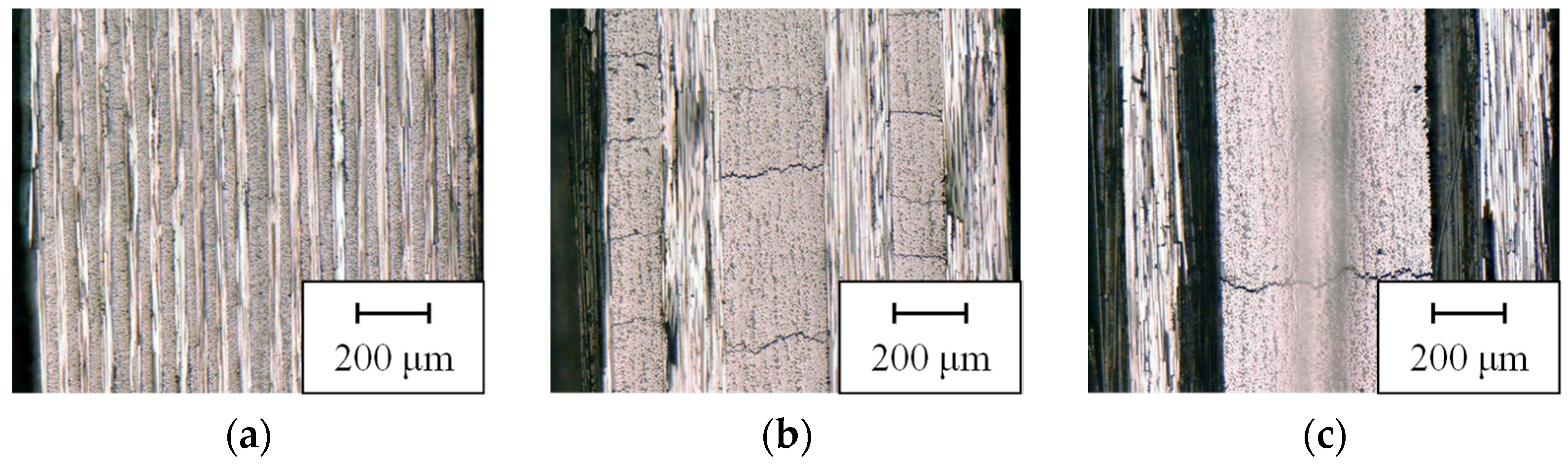
3.1. Morphologies
3.2. Static Tensile Properties
3.3. Fatigue Tensile Properties
4. Discussion
4.1. Static Tensile Properties
4.2. Fatigue Tensile Properties
4.2.1. S–N Curves
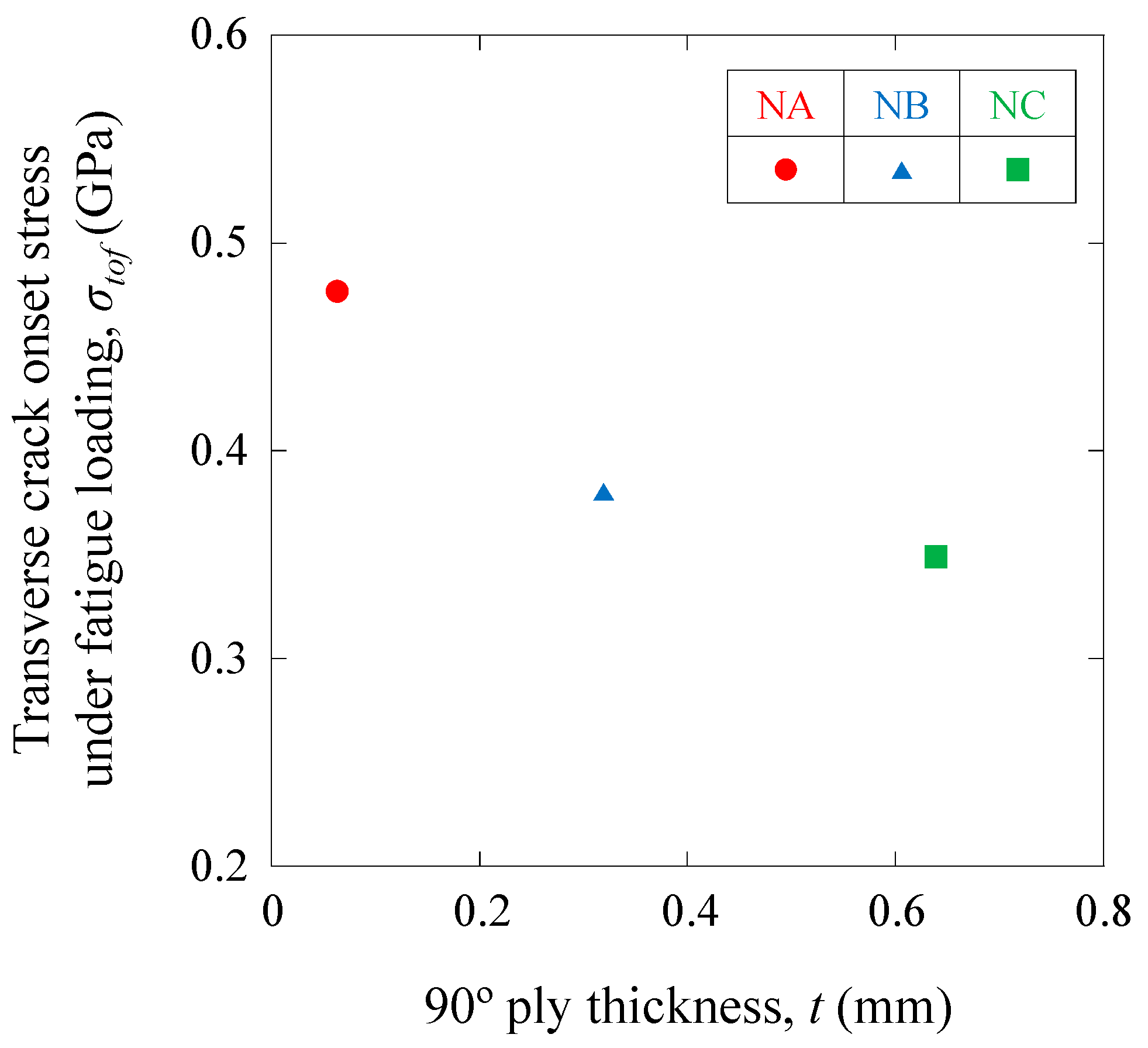
4.2.2. Transverse-Crack-Onset Stress under Fatigue Loading
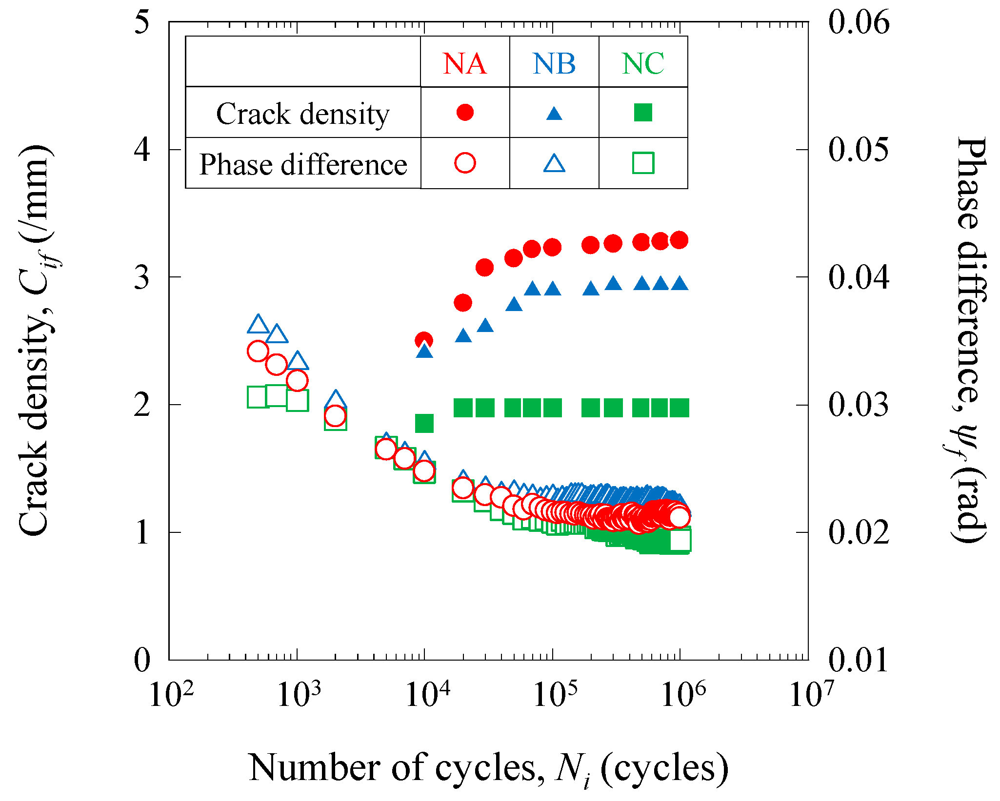
4.2.3. Fatigue-Damage-Propagation Behavior
5. Conclusions
Supplementary Materials
Author Contributions
Funding
Institutional Review Board Statement
Informed Consent Statement
Data Availability Statement
Acknowledgments
Conflicts of Interest
References
- Fitzer, E. PAN-based carbon fibers-present state and trend of the technology from the viewpoint of possibilities and limits to influence and to control the fiber properties by the process parameters. Carbon 1989, 27, 621–645. [Google Scholar] [CrossRef]
- Chand, S. Review-Carbon fibers for composites. J. Mater. Sci. 2000, 35, 1303–1313. [Google Scholar] [CrossRef]
- Guimard, J.M.; Allix, O.; Pechnik, N.; Thevenet, P. Energetic analysis of fragmentation mechanisms and dynamic delamination modelling in CFRP composites. Comput. Struct. 2009, 87, 1022–1032. [Google Scholar] [CrossRef]
- Naito, K.; Yang, J.M.; Kagawa, Y. Tensile properties of high strength polyacrylonitrile (PAN)-based and high modulus pitch-based hybrid carbon fibers-reinforced epoxy matrix composite. J. Mater. Sci. 2012, 47, 2743–2751. [Google Scholar] [CrossRef]
- Naito, K. Static and fatigue tensile properties of carbon/glass hybrid fiber-reinforced epoxy composites. Sci. Rep. 2022, 12, 6298. [Google Scholar] [CrossRef]
- Flaggs, D.L.; Kural, M.H. Experimental determination of the in situ transverse lamina strength in graphite/epoxy laminates. J. Compos. Mater. 1982, 16, 103–116. [Google Scholar] [CrossRef]
- Parvizi, A.; Garrett, K.W.; Bailey, J.E. Constrained cracking in glass fiber-reinforced epoxy cross-ply laminates. J. Mater. Sci. 1978, 13, 195–201. [Google Scholar] [CrossRef]
- Crossman, F.W.; Warren, W.J.; Wang, A.S.D.; Law, G.E., Jr. Initiation and growth of transverse cracks and edge delamination in composite laminates: Part 2. Experimental correlation. J. Compos. Mater. 1980, 14, 88–108. [Google Scholar] [CrossRef]
- Kim, R.Y.; Soni, S.R. Experimental and analytical studies on the onset of delamination in laminated composites. J. Compos. Mater. 1984, 18, 70–80. [Google Scholar] [CrossRef]
- Lavoie, J.A.; Soutis, C.; Morton, J. Apparent strength scaling in continuous fiber composite laminates. Compos. Sci. Technol. 2000, 60, 283–299. [Google Scholar] [CrossRef]
- Laws, N.; Dvorak, G.J. Progressive transverse cracking in composite laminates. J. Compos. Mater. 1988, 22, 900–916. [Google Scholar] [CrossRef]
- Lim, S.G.; Hong, C.S. Effect of transverse cracks on the thermomechanical properties of cross-ply laminated composites. Compos. Sci. Technol. 1989, 34, 145–162. [Google Scholar] [CrossRef]
- Lee, J.W.; Daniel, I.M. Progressive transverse cracking of cross-ply composite laminates. J. Compos. Mater. 1990, 24, 1225–1243. [Google Scholar] [CrossRef]
- Takeda, N.; Ogihara, S. In situ observation and probabilistic prediction of microscopic failure processes in CFRP cross-ply laminates. Compos. Sci. Technol. 1994, 52, 183–195. [Google Scholar] [CrossRef]
- Takeda, N.; Ogihara, S. Initiation and growth of delamination from the tips of transverse cracks in CFRP cross-ply laminates. Compos. Sci. Technol. 1994, 52, 309–318. [Google Scholar] [CrossRef]
- Takeda, N.; Ogihara, S.; Kobayashi, A. Microscopic fatigue damage progress in CFRP cross-ply laminates. Composites 1995, 26, 859–867. [Google Scholar] [CrossRef]
- Hashin, Z. Analysis of cracked laminates: A variational approach. Mech. Mater. 1985, 4, 121–136. [Google Scholar] [CrossRef]
- Gudmundson, P.; Weilin, Z. An analytic model for thermoelastic properties of composite laminates containing transverse matrix cracks. Int. J. Solids Struct. 1993, 30, 3211–3231. [Google Scholar] [CrossRef]
- Sasayama, H.; Kawabe, K.; Tomoda, S.; Ohsawa, I.; Kageyama, K.; Ogata, N. Effect of lamina thickness on first ply failure in multidirectionally laminated composites. J. Japan Soc. Compos. Mater. 2004, 30, 142–148. [Google Scholar] [CrossRef]
- Sihn, S.; Kim, R.Y.; Kawabe, K.; Tsai, S.W. Experimental studies of thin-ply laminated composites. Compos. Sci. Technol. 2007, 67, 996–1008. [Google Scholar] [CrossRef]
- Yokozeki, T.; Aoki, Y.; Ogasawara, T. Experimental characterization of strength and damage resistance properties of thin-ply carbon fiber/toughened epoxy laminates. Compos. Struct. 2008, 82, 382–389. [Google Scholar] [CrossRef]
- Tsai, S.W.; Nettles, A.T. Representative test data on bi-angle thin-ply NCF. JEC Compos. Mag. 2011, 48, 62–63. [Google Scholar]
- Tsai, S.W.; Papua, M. Thin-ply NCF: Design for deformation through anisotropy. JEC Compos. Mag. 2011, 48, 66–67. [Google Scholar]
- Debski, H.; Samborski, S.; Rozylo, P.; Wysmulski, P. Stability and load-carrying capacity of thin-walled FRP composite Z-profiles under eccentric compression. Materials 2020, 13, 2956. [Google Scholar] [CrossRef]
- Rozylo, P.; Falkowicz, K.; Wysmulski, P.; Debski, H.; Pasnik, J.; Kral, J. Experimental-numerical failure analysis of thin-walled composite columns using advanced damage models. Materials 2021, 14, 1506. [Google Scholar] [CrossRef]
- Debski, H.; Rozylo, P.; Wysmulski, P.; Falkowicz, K.; Ferdynus, M. Experimental study on the effect of eccentric compressive load on the stability and load-carrying capacity of thin-walled composite profiles. Compos. Part. B Eng. 2021, 226, 109346. [Google Scholar] [CrossRef]
- Rózyło, P. Failure analysis of beam composite elements subjected to three-point bending using advanced numerical damage models. Acta Mech. Autom. 2023, 17, 133–144. [Google Scholar] [CrossRef]
- Wysmulski, P. Non-linear analysis of the postbuckling behaviour of eccentrically compressed composite channel-section columns. Compos. Struct. 2023, 305, 116446. [Google Scholar] [CrossRef]
- Naito, K.; Yang, J.M.; Kagawa, Y. Development of high modulus/high strength carbon fiber reinforced nanoparticle filled polyimide based multiscale hybrid composites. Mater. Sci. Forum 2010, 654–656, 2620–2623. [Google Scholar] [CrossRef]
- Naito, K. Tensile properties of polyacrylonitrile- and pitch-based hybrid carbon fiber/polyimide composites with some nanoparticles in the matrix. J. Mater. Sci. 2013, 48, 4163–4176. [Google Scholar] [CrossRef]
- Naito, K.; Oguma, H. Tensile properties of novel carbon/glass hybrid thermoplastic composite rods under static and fatigue loading. Rev. Mater. 2017, 22, e-11843. [Google Scholar] [CrossRef]
- Tanks, J.; Naito, K.; Ueda, H. Characterization of the static, creep, and fatigue tensile behavior of basalt fiber/polypropylene composite rods for passive concrete reinforcement. Polymers 2021, 13, 3136. [Google Scholar] [CrossRef]
- Naito, K.; Shirasu, K.; Tanaka, Y. Effect of carbon fibres on the static and fatigue mechanical properties of fibre metal laminates. Fatigue Fract. Eng. Mater. Struct. 2020, 43, 1461–1472. [Google Scholar] [CrossRef]
- Higuchi, R.; Aoki, R.; Yokozeki, T.; Okabe, T. Evaluation of the in-situ damage and strength properties of thin-ply CFRP laminates by micro-scale finite element analysis. Adv. Compos. 2020, 29, 475–493. [Google Scholar] [CrossRef]
- Naito, K.; Nagai, C. Mode-I and mode-II interlaminar fracture properties of high modulus pitch-based carbon fiber reinforced polymers containing different nanostructures. J. Compos. Mater. 2022, 56, 397–407. [Google Scholar] [CrossRef]
- Shiino, M.Y.; de Siqueira, G.S.M.; Cioffi, M.O.H.; Montoro, S.R.; Donadon, M.V. Hygrothermal effect on composites under in-plane fatigue at stress ratios of R = −1 and R = 0.1: An analysis of quasi-isotropic stitched carbon fibers. J. Mater. Eng. Perform. 2018, 27, 5964–5972. [Google Scholar] [CrossRef]
- Ospina Cadavid, M.; Al-Khudairi, O.; Hadavinia, H.; Goodwin, D.; Liaghat, G.H. Experimental studies of stiffness degradation and dissipated energy in glass fibre reinforced polymer composite under fatigue loading. Polym. Polym. Compos. 2017, 25, 435–446. [Google Scholar] [CrossRef]
- Yao, W.X.; Himmel, N. A new cumulative fatigue damage model for fibre-reinforced plastics. Compos. Sci. Technol. 2009, 60, 59–64. [Google Scholar] [CrossRef]
- Epaarachchi, J.A.; Clausen, P.D. A new cumulative fatigue damage model for glass fibre reinforced plastic composites under step/discrete loading. Compos. Part A Appl. Sci. Manuf. 2005, 36, 1236–1245. [Google Scholar] [CrossRef]
- Flore, D.; Wegener, K. Modelling the mean stress effect on fatigue life of fibre reinforced plastics. Int. J. Fatigue 2016, 82, 689–699. [Google Scholar] [CrossRef]
- Stojković, N.; Folić, R.; Pasternak, H. Mathematical model for the prediction of strength degradation of composites subjected to constant amplitude fatigue. Int. J. Fatigue 2017, 103, 478–487. [Google Scholar] [CrossRef]
- Peijs, T.; Rijsdijk, H.A.; deKok, J.M.M.; Lemstra, P.J. The Role of interface and fibre anisotropy in controlling the performance of polyethylene-fibre-reinforced composites. Compos. Sci. Technol. 1994, 52, 449–466. [Google Scholar] [CrossRef]
- Jen, Y.M.; Huang, Y.C. Improvement in tensile quasi-static and fatigue properties of carbon fiber-reinforced epoxy laminates with matrices modified by carbon nanotubes and graphene nanoplatelets hybrid nanofillers. Nanomaterials 2021, 11, 3459. [Google Scholar] [CrossRef] [PubMed]
- Qaderi, S.; Ghadiri, M.; Najafi, M.; Imam, A.; Soleimanimehr, H. Size-dependent nonlinear vibration analysis of cracked graphene-platelets-reinforced-composites (GPLRC) plate under parametric excitation. Commun. Nonlinear Sci. Numer. Simul. 2023, 121, 107232. [Google Scholar] [CrossRef]
- Quan, D.; Murphy, N.; Ivanković, A.; Zhao, G.; Alderliesten, R. Fatigue delamination behaviour of carbon fibre/epoxy composites interleaved with thermoplastic veils. Compos. Struct. 2022, 281, 114903. [Google Scholar] [CrossRef]


| NA | NB | NC | WB | WC | |
|---|---|---|---|---|---|
| Static tensile properties | |||||
| Tensile modulus EL.ave (GPa) | 93.9 | 93.0 | 93.7 | 93.4 | 93.8 |
| (4.4) | (3.1) | (7.1) | (3.6) | (3.3) | |
| Poisson’s ratio νLT.ave | 0.042 | 0.040 | 0.043 | 0.041 | 0.043 |
| (0.001) | (0.005) | (0.009) | (0.006) | (0.002) | |
| Tensile strength σL.ult.ave (GPa) | 1.730 | 1.719 | 1.645 | 1.658 | 1.584 |
| (0.131) | (0.105) | (0.068) | (0.103) | (0.041) | |
| Failure strain εL.ult.ave (%) | 1.878 | 1.817 | 1.747 | 1.731 | 1.715 |
| (0.068) | (0.053) | (0.080) | (0.054) | (0.064) | |
| Fatigue tensile properties | |||||
| Intercept a (GPa) | 2.143 | 1.873 | 1.776 | 1.844 | 1.781 |
| Slope ab | −0.182 | −0.130 | −0.103 | −0.116 | −0.104 |
Disclaimer/Publisher’s Note: The statements, opinions and data contained in all publications are solely those of the individual author(s) and contributor(s) and not of MDPI and/or the editor(s). MDPI and/or the editor(s) disclaim responsibility for any injury to people or property resulting from any ideas, methods, instructions or products referred to in the content. |
© 2023 by the authors. Licensee MDPI, Basel, Switzerland. This article is an open access article distributed under the terms and conditions of the Creative Commons Attribution (CC BY) license (https://creativecommons.org/licenses/by/4.0/).
Share and Cite
Naito, K.; Seki, Y.; Inoue, R. Static and Fatigue Tensile Properties of Cross-Ply Carbon-Fiber-Reinforced Epoxy-Matrix-Composite Laminates with Thin Plies. J. Compos. Sci. 2023, 7, 146. https://doi.org/10.3390/jcs7040146
Naito K, Seki Y, Inoue R. Static and Fatigue Tensile Properties of Cross-Ply Carbon-Fiber-Reinforced Epoxy-Matrix-Composite Laminates with Thin Plies. Journal of Composites Science. 2023; 7(4):146. https://doi.org/10.3390/jcs7040146
Chicago/Turabian StyleNaito, Kimiyoshi, Yuto Seki, and Ryo Inoue. 2023. "Static and Fatigue Tensile Properties of Cross-Ply Carbon-Fiber-Reinforced Epoxy-Matrix-Composite Laminates with Thin Plies" Journal of Composites Science 7, no. 4: 146. https://doi.org/10.3390/jcs7040146
APA StyleNaito, K., Seki, Y., & Inoue, R. (2023). Static and Fatigue Tensile Properties of Cross-Ply Carbon-Fiber-Reinforced Epoxy-Matrix-Composite Laminates with Thin Plies. Journal of Composites Science, 7(4), 146. https://doi.org/10.3390/jcs7040146