1. Introduction
Composite materials have shown a strong increase in their versatility in recent years as well as a strong increase in demand. In particular, the wind energy and aerospace markets cannot be imagined without fiber reinforced polymers (FRP), such as glass fiber reinforced (GFRP) or carbon fibers reinforced plastics (CFRP). Carbon fibers are widely used because of their high specific strength and stiffness, which are superior to those of conventional metals and glass fiber composites. Therefore, carbon fiber reinforced plastics showed an increase in demand of 8.84% (Compound Annual Growth Rate 2010–2020) [
1]. New production sites have been built, and new applications have been found and marketed [
1].
Negative impacts from usage of this lightweight material are due to its limited recyclability and limited possibilities for circularity. Both pre-consumer waste as well as post-consumer waste are increasing, and the availability of secondary fibers is higher than the demand for recycled carbon fibers (rCF). Some of the reasons include low or unknown mechanical properties, inhomogeneous material behavior, limited possibility of simulation, and a high material price.
For this reason, the technologies of processing and evaluating recycle carbon fibers have been under steady investigation for many years starting with the work of Pickering et al. and Pimenta et al. [
2,
3,
4,
5]. The first scientific works were mostly related to the fiber-matrix separation by pyrolysis and oxidation [
6,
7,
8]. In recent years, more papers regarding solvolysis were published [
9,
10,
11,
12], and lab and medium scale devices were built [
13,
14].
After the fibers are chopped and reclaimed, they can be used for textile processes, such as carding and wet-laid technologies. The carding process offers a higher technology readiness level (TRL) as well as productivity, and many companies have started to rebuild and change their carding design to improve carbon fiber handling [
15,
16,
17,
18,
19,
20]. Fiber breakage and unstable textile properties, including the coefficient of variation (CV value) of the areal weight or varying fiber volume contents, still pose great challenges for the market access of this material.
The main advantages of the nonwoven process are excellent economic efficiency due to the high production output and high flexibility regarding properties, like the areal weight, isotropy, and degree of compaction. To be able to successfully process recycled carbon fibers on a nonwoven line, the line is modified to minimize fiber damage. The compact carding process combines several conversion processes to produce a homogeneous textile surface from a fiber blend. A major goal of recycling is to keep the fiber length as long as possible in order to enable multiple recycling cycles and, thus, contribute to a complete circular economy. Furthermore, longer CFs can contribute to better mechanical properties of the composite [
21,
22]. The minimum fiber length for carding is around 30 mm; therefore, in this paper, this threshold was chosen for the evaluation of the process.
The fibers are successively separated along the process into single fibers, which are parallelized. In technical jargon, those processes are called opening and carding. These processes are carried out by rollers, which are covered with a saw-tooth-wire—the clothing. The clothing enhances the grip between fibers and rollers [
23]. The carded fibers are finally accumulated on the doffer roller and a coherent, uniform fiber mat forms: the carding web.
The carding web builds the basis for the nonwoven fabric. As the areal weight of the carding web ranges from only 10 to 40 g/m
2, it is layered and stacked to achieve the desired areal weight and improve the handling. The stacked webs are bonded together by needling with a needle loom. The fibers are intertwined by the needles, and the resulting frictional connection with the surrounding fibers creates an irreversible bond [
24].
The production of needle-punched nonwovens has been developed and optimized for thermoplastic and/or staple fibers of natural origin. The use of fiber blends with carbon and thermoplastic fibers offers two significant advantages in the production process. First, the thermoplastic fibers act as carriers for the carbon fibers, which reduces the fiber length shortening [
25]. Second, the thorough mixing during the nonwoven formation results in minimal flow paths for the matrix [
26]. Usually, high-viscosity thermoplastics are impregnated into textile surfaces by high pressure and temperature [
27]. Nonwovens from carbon thermoplastic fiber blends do not require this step in the same way.
Nonwovens from rCF can be processed in many ways. If thermoplastic fibers are added to the carding or wet-laid process, the hybrid nonwovens can be consolidated directly by variothermal hotpressing or isothermal pressing. Pure CF nonwovens are suitable for infiltration processes, such as resin transfer molding or wet compression molding [
28]. As hybrid nonwovens already have their polymer included, process time and costs can be saved. Furthermore, the thermoplastic components are formable and weldable and can be further functionalized by injection molding.
In this study, we investigate possible improvements for dry-laid nonwovens from recycled carbon fibers on two different levels: carbon fiber and composite. At the carbon fiber level, the degree of carbon fiber breakage is studied depending on three factors. The factors are the web formation process in the carding machine, the number of worker–stripper pairs of the carding machine, and the blend ratio of thermoplastic fibers in a blend with carbon fibers. The aims on the composite level are the investigation of the mechanical influence of the carbon fiber volume content as well as the influence of different polymer types.
2. Materials and Methods
2.1. Materials and Methods at the Carbon Fiber Level
Two fundamentally different kinds of carbon fibers are used for the trials, which are representative types of recycled carbon fibers. On the one hand, carbon fiber cut-offs from textile production are employed, whose mechanical and rheological properties correspond to those of virgin carbon fibers. On the other hand, pyrolized carbon fibers are utilized, which undergo a heat treatment process during the reclamation to separate the matrix from the carbon fibers.
The pyrolysis removes the friction-reducing sizing on the surface of the carbon fibers, thus, leading to higher friction and stress on the carbon fibers during subsequent processing. In addition, the heat treatment can cause degradation of the carbon fibers, which increases the probability of breakage [
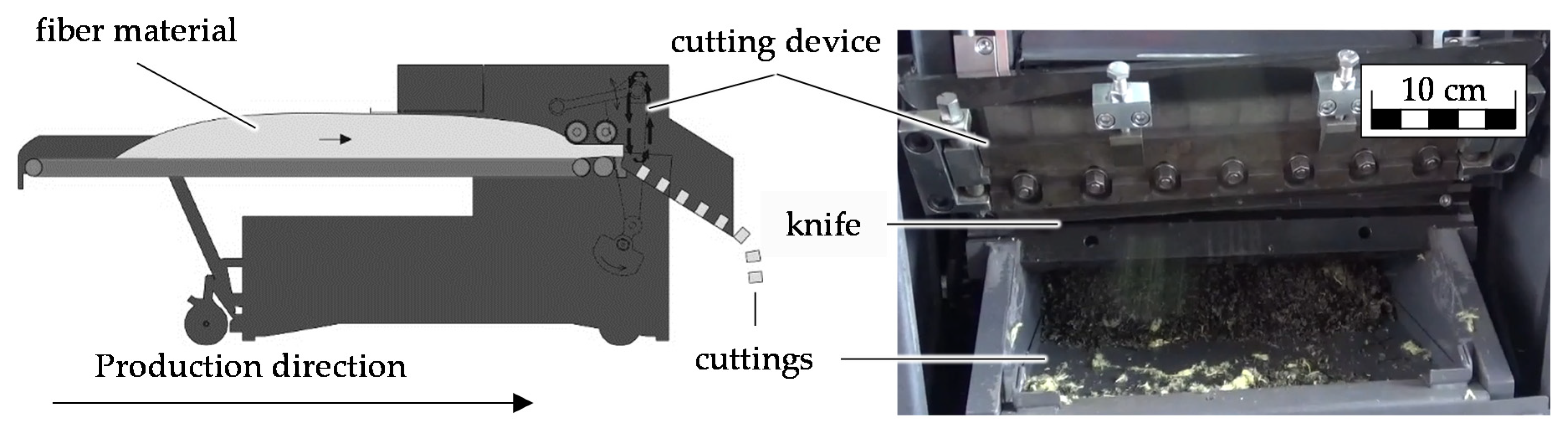
2]. The carbon fiber of type CarboNXT chopped 60,000 NP5 R (VCF) produced by CarboNXT GmbH, Stade, is a carbon fiber that originates from automotive cut-off waste and still has an intact sizing attached from the carbon fiber production.. Two length classes of VCF are used, which differ in the number of cutting procedures:
Figure 1.
Schematic representation of the guillotine cutting [
29].
Figure 1.
Schematic representation of the guillotine cutting [
29].
The pyrolized carbon fiber used was a Carbiso C SM45R 60/90 (PCF) from ELG Carbon Fibre Ltd., Coseley, UK. According to the manufacturer, the fibers are between 60-mm and 90-mm long and do not have any sizing left on the fibers. This carbon fiber originates from automotive waste but is additionally thermally treated by ELG Carbon Fibre.
Three thermoplastic (TP) fibers were used in this study as shown in
Table 1. The types P300 and P301 are polyamide 6 (PA6) fibers with different textile properties, which were produced by EMS-CHEMIE HOLDING AG, Dormat/Ems, Switzerland. In addition, a polyethylene terephthalate (PET) fiber type TREVIRA
® 290 from Trevira GmbH, Bobingen, Germany, was employed. The TP fiber properties differ in length, fineness, and crimp and are summarized in
Table 1.
Polyamid 6 is commonly used in the automotive industry and was, therefore, chosen in this study as a benchmark material. PET is widely used in textiles but is not a typical matrix material. The fibers, however, are cheaper than polyamid 6 fibers and additionally offer higher stiffness and strength values. For those reasons, this material was also investigated as a matrix material in this study. Fineness is a measure for the weight of textile fibers regarding their length. The unit dtex describes the weight in gram per 10,000 m of fiber length. The crimp is a unit for the number of curls per centimeter that a textile fiber possesses. Those curls lead to a better grip between fibers and the wires of the rolls of the carding machine.
All fibers and blends were processed at ITA Augsburg on the nonwoven line KC11 2–4 SD/MEK 11 from Dilo Systems GmbH, Eberbach, at ITA Augsburg. Three separate trial series were conducted to investigate the influence on the carbon fiber length, which is explained in detail in the following subsections.
2.1.1. Materials and Methods for Investigating the Influence of Web Formation on Carbon Fiber Length
In the first trial series, three different fiber blends were processed with the nonwoven line using a fixed set of machine parameters to determine the influence of the web formation process on the carbon fiber length. Therefore, the carbon fiber VCF3x was processed pure and as a blend with 60 wt% of the polyamid6 fiber PA6-40-1.7. Preliminary trials showed that a thermoplastic fiber content of 60 wt% was sufficient for a secure consolidation and production of composites, which are used for mechanical testing in the later stages of the study. The pyrolized carbon fiber PCF was only processed as a blend with 60 wt% of the PA6-40-1.7 since the high fiber-metal friction was expected to result in severe fiber length losses in the pure processing of pyrolized carbon fibers. The materials and the respective ratio of mixture are shown in
Table 2.
The influence of the web formation by the carding machine was analyzed by measuring the fiber length at four positions along the carding machine. The fiber length measuring positions as well as the machine setup used are shown in
Figure 2.
The first fiber length measuring position (pos. 1) is located on the belt weigher. The results at this position are the reference. The second fiber length measuring position (pos. 2) is located at the second worker roll of the pre group giving the length reduction caused by the material intake and the pre group. The third fiber length measuring position (pos. 3) is located at the third worker roll of the main group. The results show the length reduction caused by the main group where the most intense carding takes place. The fourth fiber length measurement position (pos. 4) is located after the carding machine. The samples are taken directly from the web, and the results are used to evaluate the shortening effect of the web formation on the doffer roller.
2.1.2. Materials and Methods for Investigating the Influence of Worker–Stripper Pair Numbers on Carbon Fiber Length
In the second trial series two different machine setups were investigated where three and six active worker–stripper pairs were employed as shown in
Figure 2. Between the worker rollers and the main rollers, the fibers were carded. Carding is a trade-off between fiber orientation and fiber damage. The degree of fiber orientation in the web is directly related to the number of worker–stripper pairs.
Six worker–stripper pairs were the maximum number possible in the current machine setup resulting in a high degree of orientation, which is desired in the web. Three worker–strippers were chosen as the minimum number as this number still provides acceptable fiber orientation while significantly reducing stress on the fibers. To evaluate the influence of the machine setup, the carbon fiber VCF1x was processed using three and six active worker–stripper pairs (
Table 3(a)) measuring the carbon fiber length on the belt weigher and on the produced web.
2.1.3. Materials and Methods for Investigating the Influence of Blend Ratio of Thermoplastic Fibers and Carbon Fibers on Carbon Fiber Length
In the third trial series, the influence of different blend ratios between thermoplastic fibers and carbon fibers is investigated using three and six worker–stripper pairs, respectively. The trials using three active worker–stripper pairs are designed to study the lowest possible damaging of carbon fibers with the nonwoven line. Therefore 60 wt% of thermoplastic fibers are used as shown in
Table 3(b).
The tests with six active worker–stripper pairs serve to investigate the influence of a small quantity of thermoplastic fibers when the carbon fibers are subjected to the highest possible stress. Therefore, 10 wt% of thermoplastic fibers are used as shown in
Table 3(c). Although the addition of 10 wt% of thermoplastic fibers will not suffice to a complete wet out of a composite, the effect on fiber length reduction is significant and is thus investigated. Small amounts of thermoplastic fibers could be used to greatly enhance the fiber length of carbon fiber nonwovens used solely for resin impregnation. Carbon fiber samples are taken for measurement on the belt weigher and the web (fiber length measuring positions 2 and 4, respectively, shown in
Figure 2).
2.1.4. Carbon Fiber Length Measurement
The length of the carbon fibers from each position was measured by the two-tweezers method in accordance to DIN 53808-1. The sample size included 200 single carbon fiber measurements. The results were sorted into length classes of 5- or 1-mm width. Thus, the mean fiber length and the fiber length distribution were determined as shown in fiber length diagrams. Due to the manual procedure and the subjective selection of carbon fibers by hand as well as the fracture behavior of the recycled carbon fibers under mechanical load, this procedure is prone to errors.
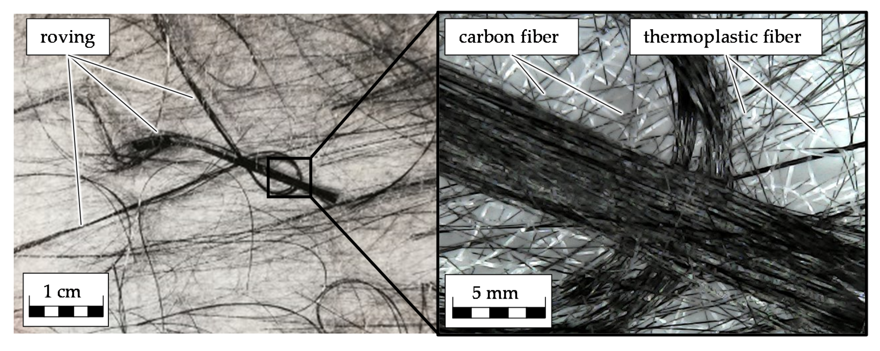
Therefore, the fiber length measurement was carried out by a designated person to minimize the subjective influence during testing. Since individual carbon fibers break during handling with tweezers, the measuring concentrated on rovings—carbon fiber bundles consisting of several thousand individual fibers—instead (
Figure 3). The rovings account for 15.6 wt% of the carbon fibers [
30]. Although the fiber length measurements, thus, only cover a small portion of the carbon fibers there is, at present, no more sophisticated measuring method available.
To assess the significance between the fiber lengths at different positions, statistical methods were employed. The Kolmogorov–Smirnov test was used to determine whether the data is normally distributed, which does not apply to the fiber length measurement. Therefore, the Mann–Whitney test was used to calculate the probability of the null hypothesis [
31]. The null hypothesis states that the mean values of fiber length at different positions do not show any significant difference between them. The alternative hypothesis states that the calculated mean values do show a significant difference between them. The significance level is 5%. If the probability of the occurrence of the null hypothesis is less than 5%, the significance level is fulfilled, and the null hypothesis is rejected.
2.2. Material and Methods at the Composite Level-Bending Properties of rCF Nonwoven Panels
The second part of our investigation focuses on the composite properties of carbon fiber nonwoven reinforced plastics. The nonwovens are processed into panels at Fraunhofer IGCV in Augsburg. A complete list of the used materials is shown in
Table 4. The variable parameters are carbon fibers from cut VCF and pyrolized carbon fibers PCF, the amount of worker–stripper pairs, the properties of the thermoplastic fibers and the proportion of thermoplastic fibers of the blends.
An LZT-OK-130-L press from the company Langzauner GmbH, Lambrechten (AUT), with a maximum force of 1370 kN was used to manufacture 2-mm thick samples, which were mechanically characterized afterwards. Therefore, in dependence to the areal weight, 10–11 layers of the nonwoven were stacked above each other without rotating them to enable a clear evaluation of the machine and the cross direction properties. The TK 350 × 350 mm2 tooling was used for the production of the samples because, here, the material only has limited contact with the air due to the optimized gab geometry.
For PA6 and PET hybrid nonwovens, a pressing temperature of 290 °C was set. The temperature was controlled at the top and bottom part of the tooling as well as inside the sample. The maximum deviation of temperature was about 10 K. For the pressing, a variothermal process was used starting at room temperature and compressing the material with 50 kN (4 bar). Afterward, the material was heated with 10 K/min until it reached the maximum temperature.
Then, the maximum pressure up to 50 bar was applied to the material without dwell time. The material was cooled down by 10 K/min with an isobar pressure of 50 bar. In dependence of the fiber volume content, homogeneity, and polymer viscosity, those parameters were slightly changed to achieve the optimal result. After the consolidation, the thickness of each panel was measured, and the surface quality was evaluated visually. If the panel met the required quality criteria, it was used for mechanical testing.
After the consolidation, the samples were cut from the panel by water jet cutting. Ten samples in 0°, +45°, −45°, and 90° were cut from the panel. In respect to the previous measurements, six samples were used for the bending test because this allows a statical evaluation in an appropriate quality. The others were used for the fiber volume content determination according to a wet-chemical solvolysis (DIN EN 2564).
The bending tests were carried out according to DIN EN ISO 14125 and in compliance with the four-point bending set-up. Material class II was assumed, and therefore samples of 40 × 15 × 2 mm3 were manufactured. After the testing, the average values as well as the standard deviation were calculated. Broken samples were used for cross section images to gather more information regarding the quality of the impregnation.
3. Results
The results are discussed in two parts. First, the results of the fiber length measurements regarding the web formation, machine setup, and blend ratio of thermoplastic fibers are presented. The second part shows the results for the investigation of the mechanic bending properties of nonwoven reinforced plastics regarding the carbon fiber volume content and the use of different thermoplastic fibers.
3.1. Results of the Fiber Length Measurements Regarding the Web Formation, Machine Setup, and Blend Ratio of Thermoplastic Fibers with Carbon Fibers
3.1.1. Results of the Fiber Length Measurements Regarding Web Formation
The results of the fiber length measurements conducted during the web formation are shown in
Table 5. The average carbon fiber length prior to the carding process ranges from 59 to 62.3 mm with more than 72.6% of fibers being over 30-mm long. During the process, the fibers lost between 20.6% up to 28.4% of length. Pure carbon fibers and pyrolized carbon fibers showed a higher reduction in length. The addition of thermoplastic fibers reduced the fiber shortening by almost 28% for VCF.
The quantity of fibers over 30 mm decreased for all tested blends during the process. The VCF_PA6 showed the least reduction (3.4%), and PCF_PA6 showed the highest reduction (12.4%). The relatively lower starting point of 72.6% of fibers over 30 mm for VCF3x_PA6 was caused by the fiber preparation, which was passed by all materials prior to the measuring location at pos. 1. The fiber preparation contained a suction system, and it mixed and dosed the materials leading to different starting values.
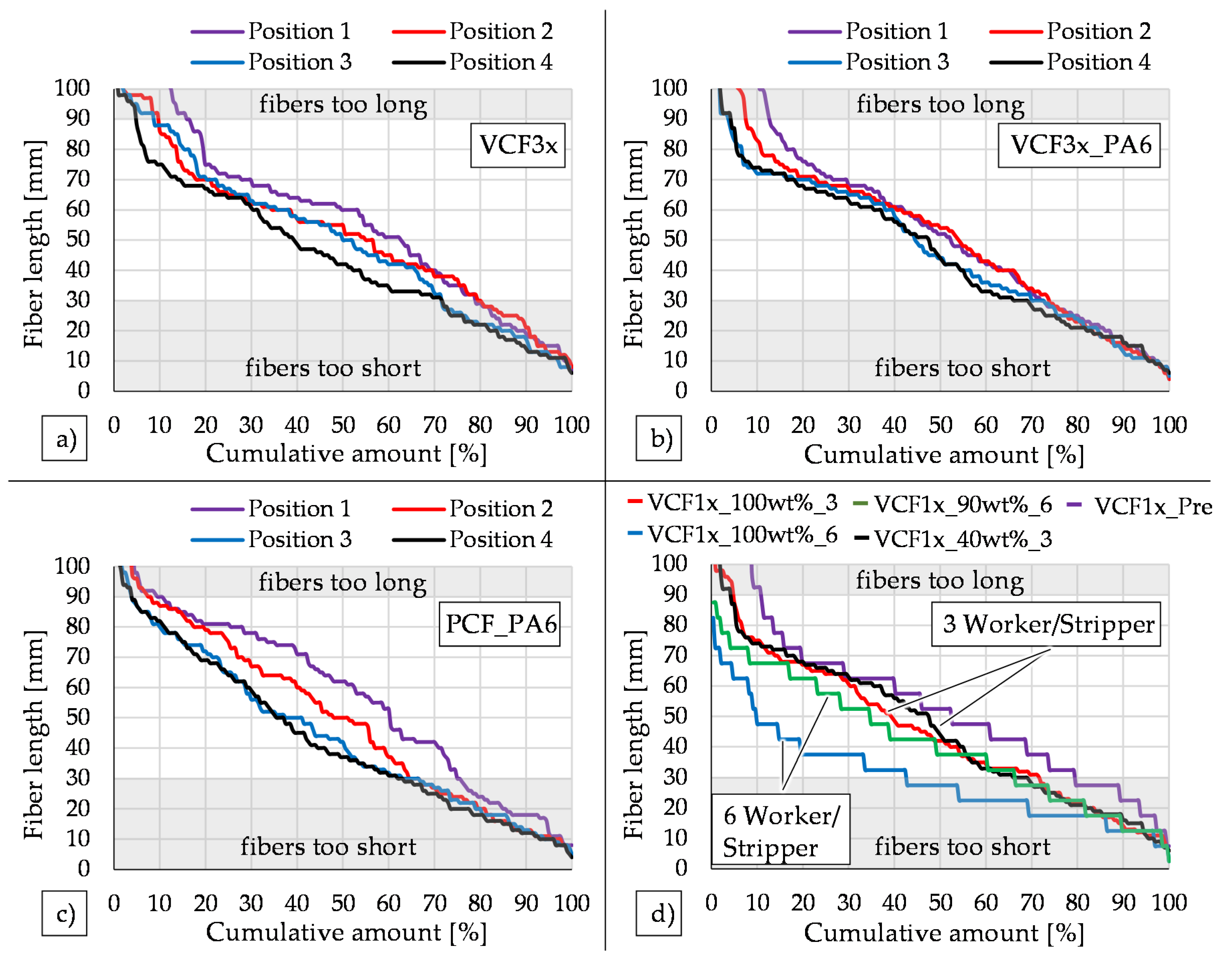
Figure 4a–c represent carbon fiber length diagrams of the three processed materials. The optimal length for the used nonwoven process was between 30 and 90 mm. The carbon fiber length curves of VCF3x, VCF3x_PA6, and PCF_PA6 show a shift to the left as the web formation process progresses, indicating fiber length loss due to mechanical stress on the fibers from the carding process.
In
Figure 4a, a clear shift to the left is observed for fibers above 40 mm from pos. 1 to pos. 2. Below the 70-mm carbon fiber length, the graphs of pos. 2 and pos. 3 are almost identical. Above this threshold, the quantity of longer fibers is reduced. From pos. 3 to pos. 4, a distinct decrease in carbon fiber length is observed between 35 and 60 mm, and the amount of longer fibers decreases even further. All changes are significant as stated in
Table 6 except for pos. 2 to pos. 3, which are almost identical.
The length reduction is greatly reduced, and the doffing between pos. 3 and pos. 4 shows almost no shortening of the fibers. At the same time, more fibers are below 30 mm. One reason is the crimp of the thermoplastic fibers. Short carbon fibers are retained by the thermoplastic fibers in the web, and thus the suction system of the card draws fewer short carbon fibers from the mixture [
30].
The carbon fibers of the PCF_PA6 blend were longer than the carbon fibers of VCF. The reduction from pos. 1 to pos. 2 is visible by a prominent left shift for all fibers shorter than 80 mm. Fibers above were not affected. A shortening between pos. 2 and pos. 3 is visible for fibers above 30 mm. Nevertheless, no significant difference can be proven. Pos. 3 and pos. 4 are almost identical.
The results of
Table 6 were used to distinguish between parts of the carding machine with high and low carbon fiber length reduction. The carding machine exhibited a significant carbon fiber length reduction when processing VCF3x, which is supported with statistical significance. Only the main group located between pos. 2 and pos. 3 showed no significant fiber length reduction. The reduction in carbon fiber length for VCF3x_PA6 between two positions next to each other—pos. 1 to pos. 2, pos. 2 to pos. 3, and pos. 3 to pos. 4—is too small to be distinguished with statistical significance.
Between pos. 1 and pos. 3 as well as between pos. 1 and pos. 4, which contains the complete carding machine, the carbon fiber length was reduced with statistical significance. The length of the carbon fibers of the blend PCF_PA6 were reduced significantly at the intake and the pre group. The shortening in carbon fiber length caused by the main group (pos. 2 to pos. 3) and the doffing (pos. 3 to pos. 4) was not statistically significant. The pyrolized carbon fiber length was, however, statistically significantly reduced if the main group and the doffing are considered together as shown by the validation of significance between pos. 2 to pos. 4.
3.1.2. Results of the Fiber Length Measurements Regarding Machine Setup
The diagram in
Figure 4d presents the fiber lengths before and after the nonwoven process using different machine setups. The processing of the pure carbon fiber VCF1x_100wt%_6 with six active pairs of workers and strippers exhibits an average fiber length reduction of 49%. The processing with three worker–stripper pairs led to a length reduction of 28.4%.
3.1.3. Results of the Fiber Length Measurements Regarding the Blend Ratio of Thermoplastic Fibers and Carbon Fibers
Processing a thermoplastic carbon fiber blend with 60 wt% thermoplastic fibers using three active worker–stripper pairs led to a reduction of carbon fiber length of 20.6%. This corresponds to a decrease of 27.5% in comparison to the processing of pure carbon fibers with the same machine setup. When six active worker–stripper pairs were used to process a blend of 10 wt% thermoplastic fibers and 90 wt% carbon fibers, the carbon fiber shortening was reduced from 49% to 21.5%, which is a reduction of 56%.
3.2. Mechanical Evaluation rCF Nonwoven with Different TP-Fibers and Fiber Volume Content
The produced panels were tested by four-point bending. The results of each test were used to calculate an average mechanical value in each of the four directions and its standard deviation. For the investigation of the orientation and isotropy, different approaches can be found in literature. In this paper, the orientation ratio of a nonwoven material is described as the ratio of the highest average stiffness divided by the lowest. For carded material, that usually means bending strength at 90° in direction σ90° divided by the bending strength at 0° in direction σ0° because of the higher orientation in 90° due to the cross-lapping process.
For the investigation, the average values were calculated by the mean values of all four testing directions (0°, +45°, −45°, and 90°) and compared to the ratio of the 90° value divided by the 0° value. Those values show very similar numbers. Therefore, the 90° to 0° average value was used in this study. The influence of the fiber volume content was investigated. The mechanical properties of the samples were not normalized to a fixed fiber volume content, which is usually done with a linear recalculation to be able to directly compare samples of different fiber content.
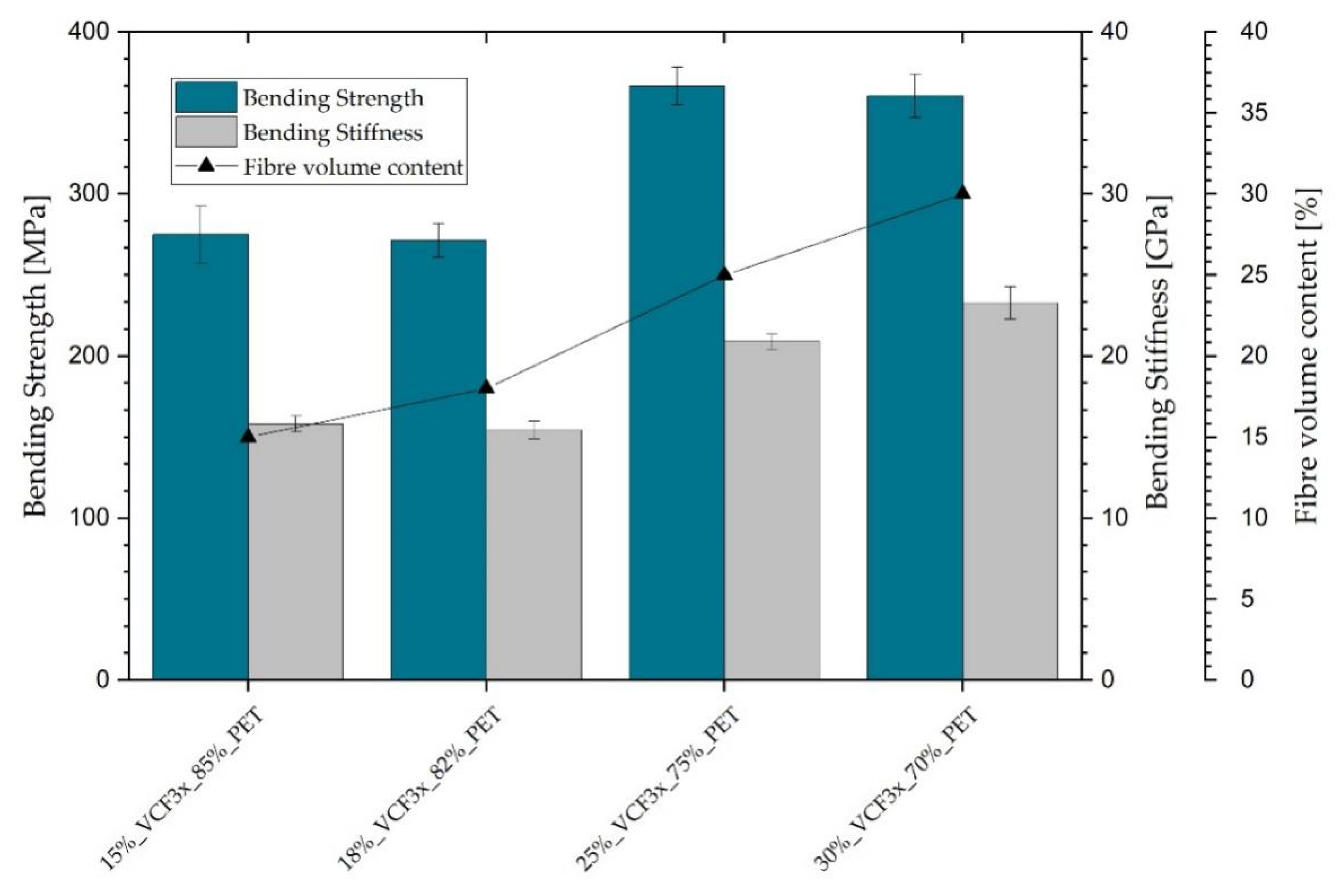
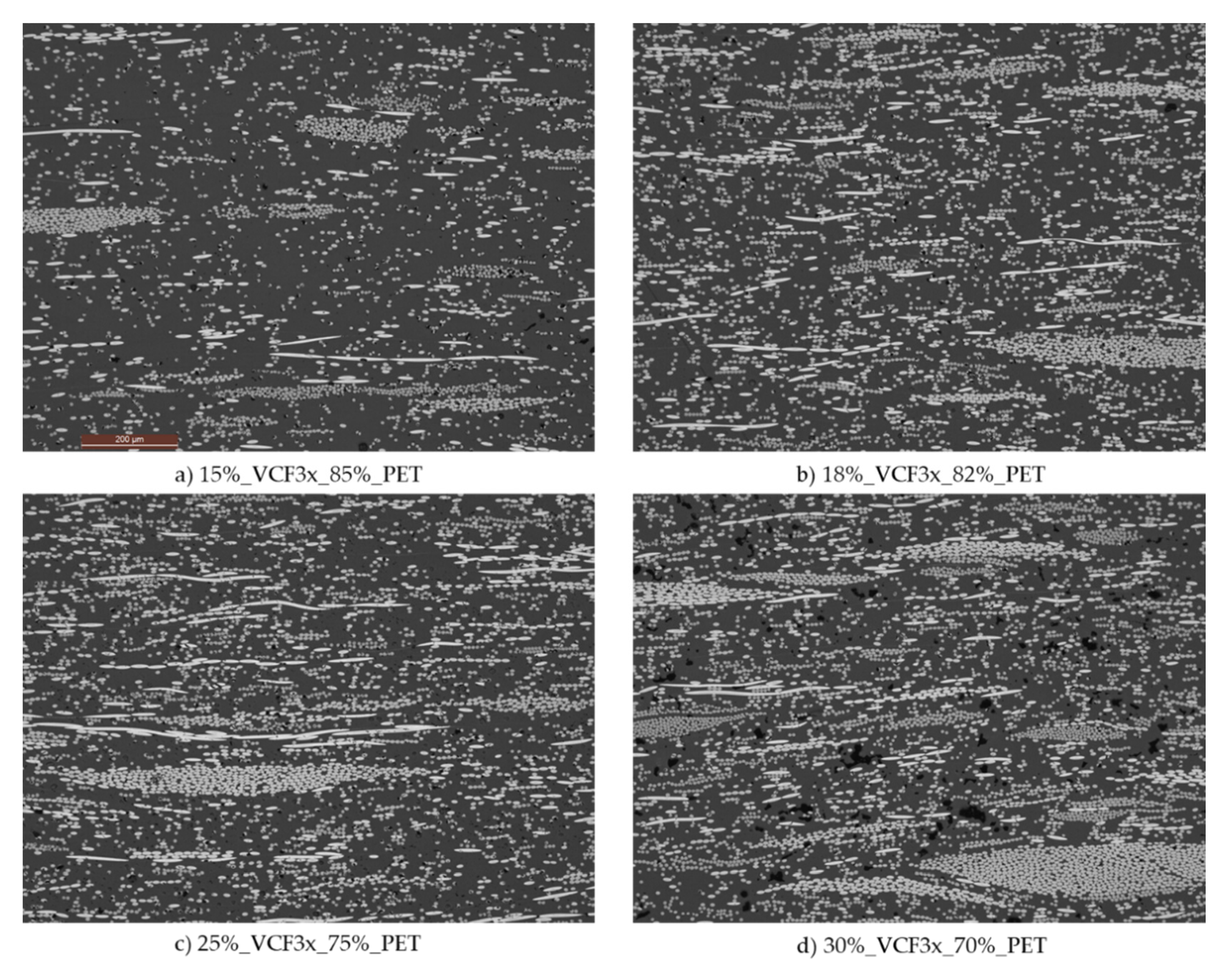
The investigated PET materials (
Figure 5) had fiber volume contents of 15%, 18%, 25%, and 30%. The properties of the 15% and 18% material were very similar. This similarity highlights that the deviation of the material was higher than the theoretical increase of performance by adding 3% carbon fiber. With a higher fiber volume content of 25%, the stiffness and strength increased by 32–33%. The material with 30% content of fibers did not, however, show any further increase of its strength and showed a slight increase in stiffness.
Overall, a stiffness of 15.8 GPa for the 15% material and 23.3 GPa for the 30% FVC material are reported. The bending strength showed a minimum of 275 MPa and a maximum value of 366 MPa for the 18% and 30% material, respectively. All those values are additionally shown in
Table 7. In addition to the mechanical properties, cross section images are made to determine the quality of impregnation and fiber breakage (
Figure 6).
In addition to the investigation of the FVC influence, the effects of different textile properties of the fibers as well as different machine setups on the mechanical properties of nonwoven reinforced composites were evaluated. Four different polymer fibers blended with the same fiber volume content of PCF were used to manufacture nonwovens. The blends are shown in
Table 8. The materials were used for sample production by hot-pressing and mechanical characterization by four-point-bending.
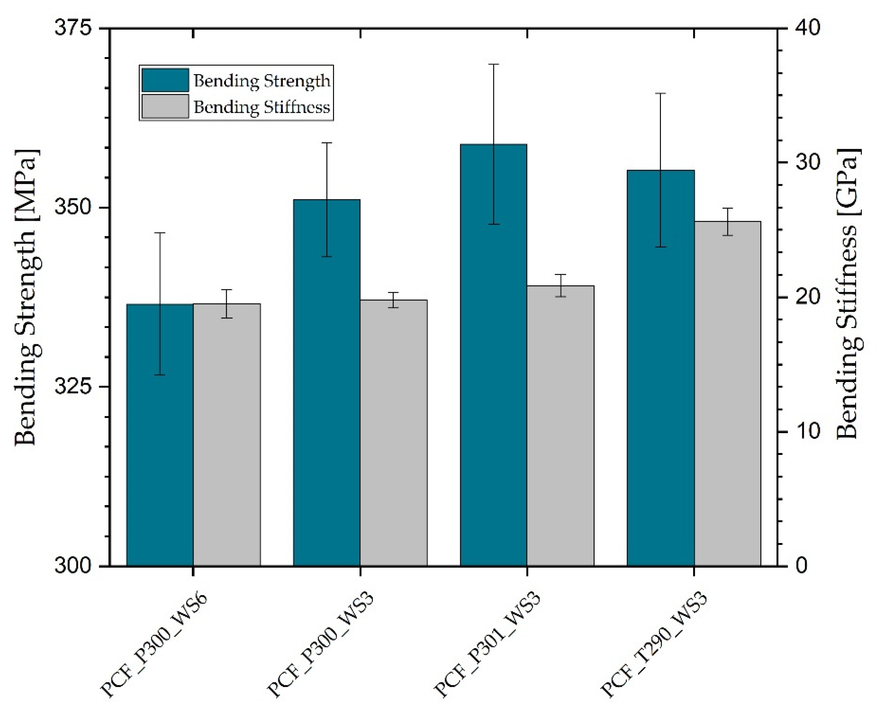
Figure 7 shows the bending strength and bending stiffness of those materials.
The axis of the strength is zoomed in to highlight the effect. The illustrated values are average values of the 0° and 90° directions. The PCF_P300_WS6 fiber blend showed the overall lowest properties with a 336 MPa bending strength and 19.5 GPa bending stiffness. The reduction of worker–stripper pairs from six to three led, on average, to an increase of bending strength by 4.4% to 351 MPa and to an increase of bending stiffness by 1.5% to 19.8 GPa. By changing the textile properties of the thermoplastic fibers—the fiber length, fineness, and crimp—an increase to 358 MPa (+6.5%) for strength and an increase to 20.9 GPa (7.2%) for stiffness were achieved.
The PA6 materials had a similar fiber volume content (31–33%), and thus it can be assumed that there should be no influence on the mechanical properties according to the results in the previous trials. Compared to PA6, the use of PET strongly increased the average bending stiffness to 25.6 GPa. This material also had a slightly lower fiber volume content (30%), and therefore the potential of the use of PET for stiffness driven applications is even higher. The strength could not be increased using PET fibers, however, and the average value at 355 MPa was even lower than for PCF_P300.
In the cross direction (90°), the average tested value was 30.1 GPa, and, in the machine direction, 21.2 GPa. The orientation ratio calculated to 1.42 for the PET/rCF nonwoven. In comparison, the PCF_P300_WS6 showed an almost isotropic behavior with an orientation ratio of 1.13. The orientation ratio was increased to 1.56 by changing the PA6 properties using fiber type P301, which is longer, less fine, and less crimped. Longer, thicker, and less crimped fibers not only increased the overall properties but also the orientation degree of the web and, therefore, influenced the overall nonwoven orientation and orientation ratio.
4. Discussion
A study by Dauner et al. investigated the length reduction by the position of the card [
25]. Although the setup of the nonwoven machine was not explicitly stated, the carding was similar, and the roller cards were constructed in similar ways. The results are compared to the current findings in
Table 9.
The length reduction was strongest at the beginning of the carding machine for all measured fibers and blends. The length reduction in comparison to previous works showed a lower overall shortening. Possible reasons for the shorting at the intake and the pre group are the clamping of the fibers at the intake where fibers are torn leading to high mechanical stress and fiber breakage. The carbon fibers were, furthermore, unscathed at the intake, and thus the decrease in carbon fiber length due to the first contact with rollers and wires is most significant. Concerning fiber blends, the subsequent positions were each reduced in their effective shortening. Pure VCFs, however, were shortened by only 4.6% from pos. 2 to pos. 3 but 10.8% to pos. 4, reversing the effect. The reduction of the carbon fiber length between pos. 2 and pos. 3 was caused by the main group, consisting of the main roller and four pairs of worker–strippers. In this part of the machine, the highest degree of fiber separation, parallelization, and blending takes place. These operations result in increased mechanical stress on the carbon fibers, which ultimately leads to fiber breakage. More brittle fibers, such as PCF, which may be degraded by the pyrolysis process, showed a higher degree of carbon fiber length reduction. The VCFs used in this study, on the other hand, are likely already too short to be further damaged by the main group.
The web formation on the doffing roller is located between pos. 3 to pos. 4. The VCF and PCF blends did not show any significant reduction in carbon fiber length at this location. The thermoplastic fibers presumably ensured a dampening effect for the carbon fibers during the web formation. The fibers were slowed down significantly, and thermoplastic fibers might dampen the extreme forces caused by the deceleration. Pure VCFs, however, were not cushioned and exhibited a significant decrease in carbon fiber length due to the high mechanical stress as the results show.
Pure carbon fibers and pyrolized carbon fibers showed a higher reduction in length. The pyrolized fibers were more brittle after the reclamation process and the friction reducing sizing. The thermoplastic fibers in the blends had two opposite effects. On the one hand, the fibers functioned as a cushion for the carbon fibers and reduced the fiber damage especially for longer carbon fibers. The effect was shown by the addition of 10 wt% TP fibers in different machine setups, which led to a reduced fiber shortening up to 58%.
On the other hand, the crimped thermoplastic fibers kept shorter carbon fibers in the web. Therefore, this increased the amount of short fibers that are otherwise removed by the suction system of the carding machine. The decreasing quantity of fibers over 30 mm proved this effect, which was highest for VCF and significantly lower for the blends with thermoplastic fibers. This could also be the reason for the reversed amount of shortening by position observed for the processing of VCF.
Another key finding is the positive influence of less worker–stripper-pairs on the fiber length. With three worker–stripper pairs, the length reduction decreased substantially, while the mechanical results did not show lower orientation values. In fact, the mechanical values became higher as shown in
Figure 6.
The comparison of the measured bending properties in
Figure 5 indicates that an increase of the bending strength as well as the bending stiffness occurred due to the rising fiber volume content. This fits the Voigh–Reuss–Hill assumption of an isotropic material [
32,
33]. It was shown that a rising fiber volume content has an influence on the mechanical properties especially in terms of bending load. However, the observed effect is not always linear and, therefore, does not follow the rule of mixtures for fiber-reinforced polymers.
One reason is that the deviation of mechanical properties is strongly influenced by the carbon and thermoplastic fiber properties as well as the carding adjustments and is not based only on the principles of load distribution onto the reinforcement fiber. By increasing the FVC from 15 vol% to 30 vol% of carbon fibers, the strength can be increased by 33% of the original strength and the stiffness by 50% of its original value. Still, the materials with 25 vol% showed a similar mechanical behavior to the 30 vol% material, which proves that the strength and stiffness were limited.
A similar effect was shown by Pickering et al. [
3]. He also demonstrated that the stiffness of a nonwoven web can be increased by fiber volume content in a linear correlation in certain limits. On the other hand, the strength began to drop at a critical fiber volume content. His measurements were applied to a thermoset material and are, however, not completely transferable to this thermoplastic nonwoven study. One reason for the non-linearity of correlations could be due to the infiltration quality by the thermoplastic fibers within the hot-pressing route.
Textile TP fibers have relatively high viscosities due to the spinning process. In the pressing process, the polymer chains need to be melted, and the viscosity should be reduced as much as possible to achieve a good impregnation behavior. With a higher fiber volume content, the isotropic nonwoven material has a lower permeability and is, therefore, harder to infiltrate. This leads to dry spots and fiber shortening by pressing onto dry fibers that are not embedded by the resin. This effect can be seen by the cross-section images in
Figure 6. The 15%, 18%, and 25% material did not show many pores, but the 30% materials showed a higher density of fibers as well as a higher amount and size of voids within the material cross section.
By increasing the orientation ratio, the in-plane permeability can be increased, and higher fiber volume contents could be possible. Within the project MAI CC4 Carina [
19,
20], the project partners were investigating the correlation of the orientation ratio, the fiber volume content, and the mechanical performance. It was shown that up to 38 vol% fiber volume content was possible, and the mechanical properties could be further increased. However, there are other complications in the thermoplastic processing route for such high fiber volume contents. By using a thermoset polymer or TP powder polymer, the infiltration can be improved, and higher fiber volume contents are achievable.
The second mechanical investigation in this study was the influence of different TP fiber properties on the bending properties. By the reduction of the worker and stripper pairs, the composite strength was increased by 4.5%. In changing the textile properties to thicker, longer, and less crimped fibers, the orientation ratio of the web and the nonwoven were increased as well. The average strength was increased slightly by 1.9% and the stiffness by 5.5%. Although those increases were not statistically significant and, therefore, only represent a trend.
By using PET instead of PA6, the stiffness was improved by 22.4%, while the strength remained on the same level. PET exhibits a higher stiffness in comparison to PA6, which also transfers to the improved mechanical properties of PET nonwoven panels compared to PA6 nonwoven panels. The high availability of recycled PET and circularity could suggest PET over PA6 for the material choice of future sustainable materials. In conclusion, we demonstrated that the choice of polymer, as well as the textile properties and the machine setup, have a strong influence on the mechanical properties of nonwoven reinforced composites.


