
The Design of Carbon Fibre Composite Origami Airbrakes for Endeavour’s Darwin I Rocket


Abstract
1. Introduction
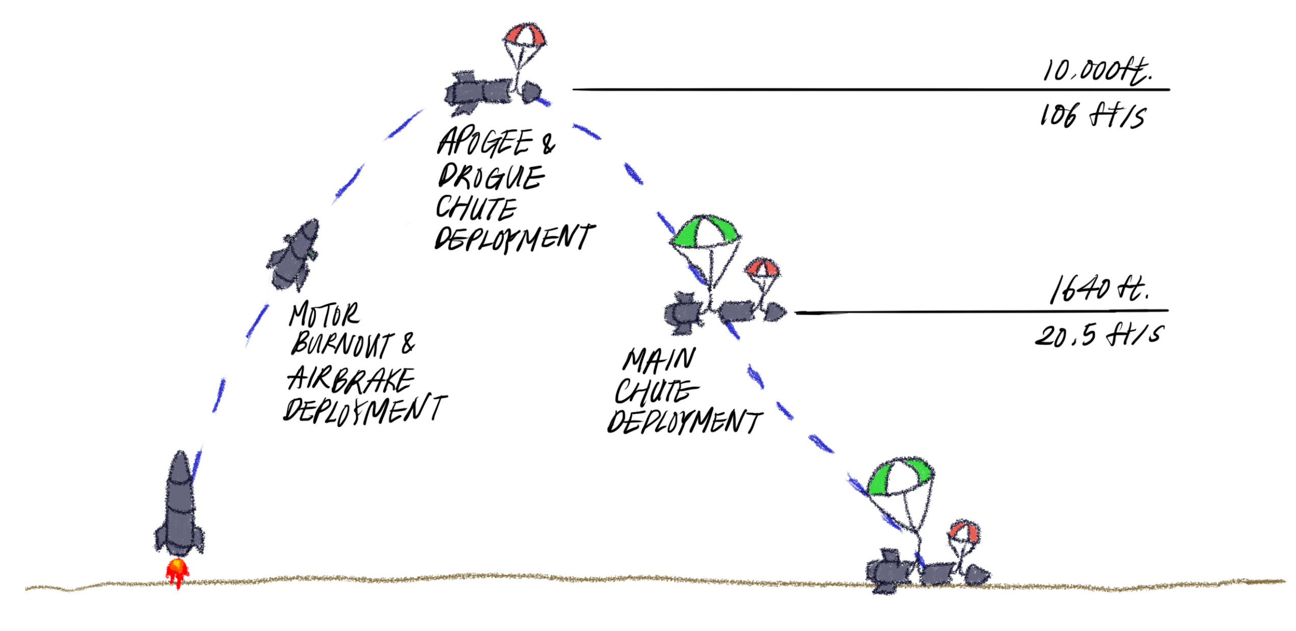
1.1. An Introduction to Rockets, Dynamics, and Air Brakes
1.2. Origami Structures
1.3. Actuation of Origami Structures
2. Materials and Methods
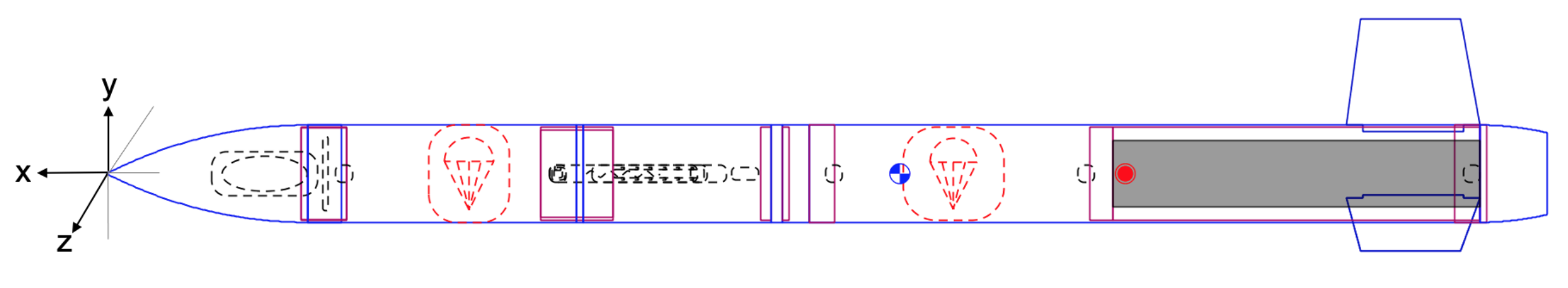
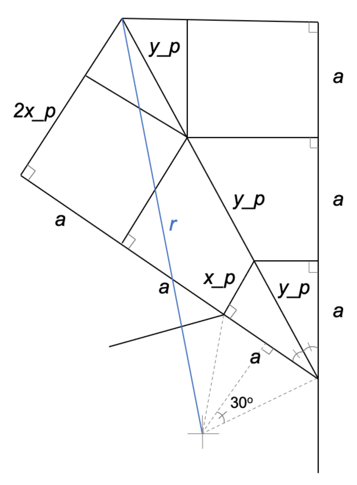
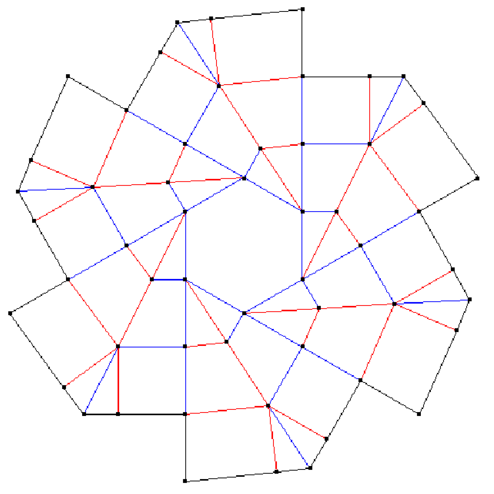
2.1. Geometrical Modelling and Design
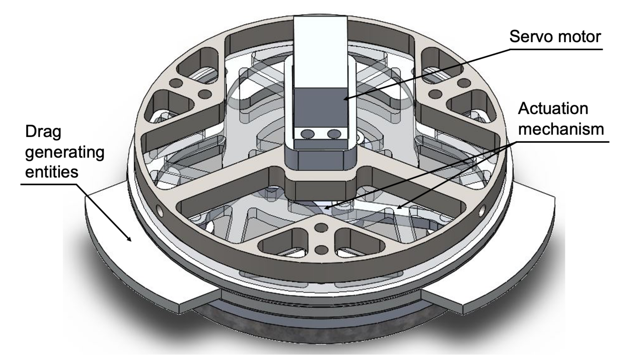
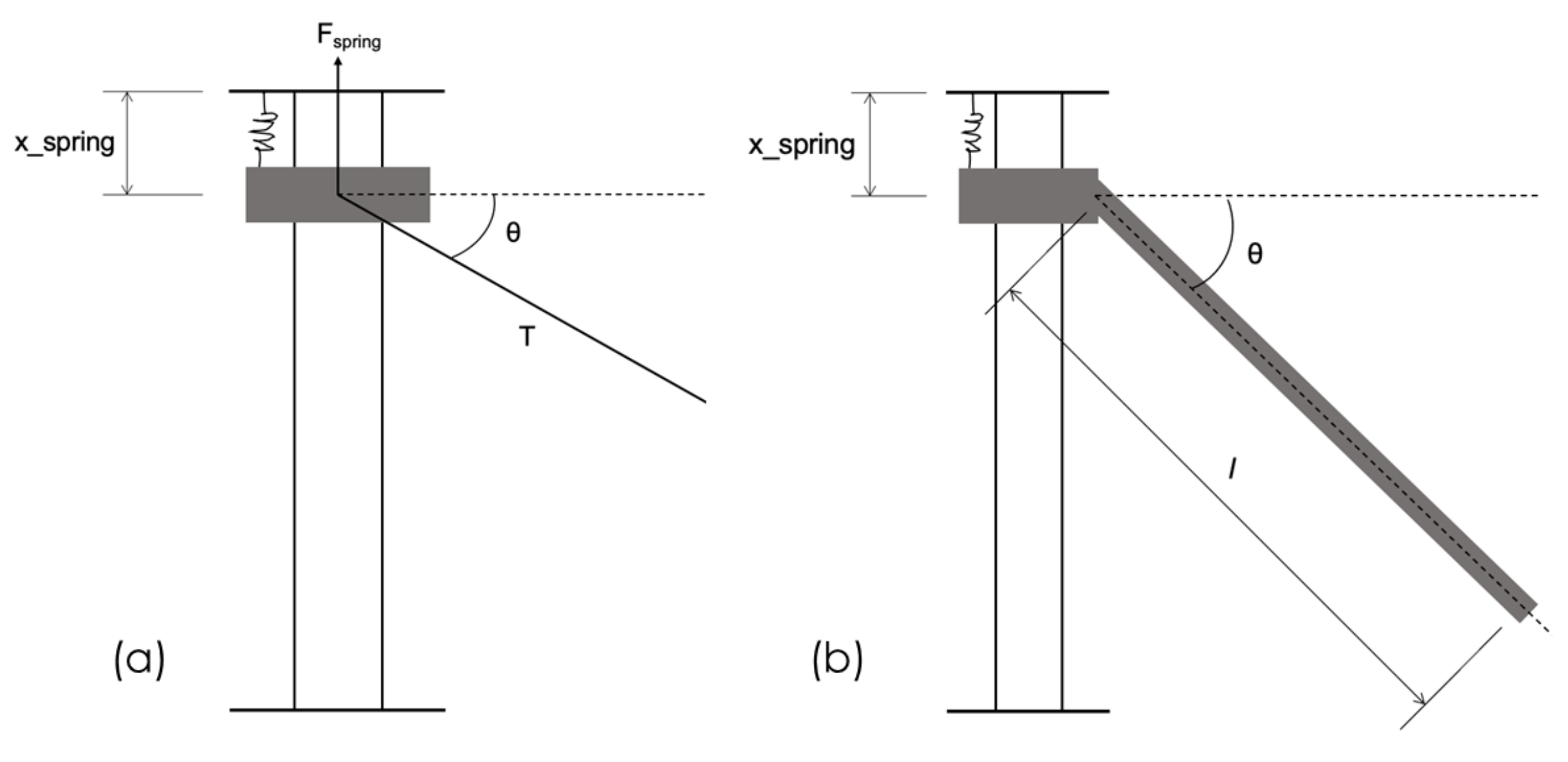
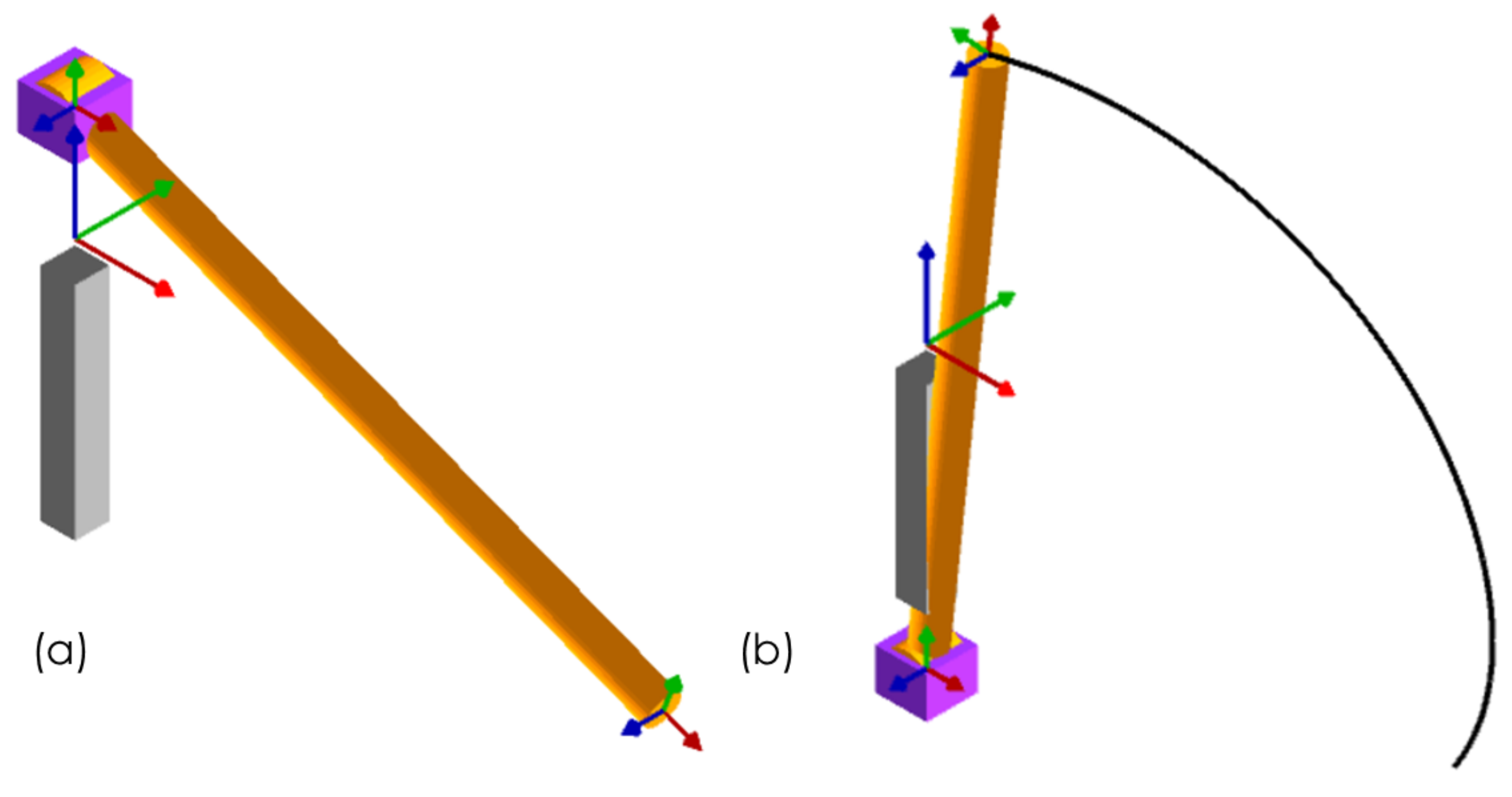
2.2. Design of the Actuation System for the Composite Flasher
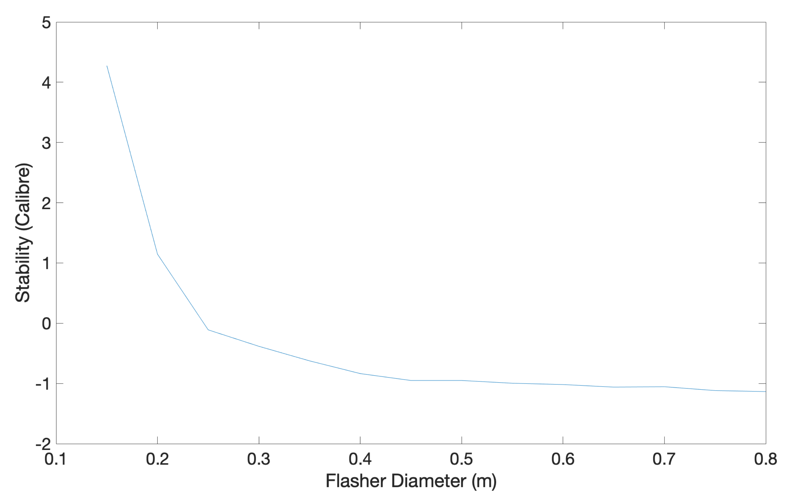
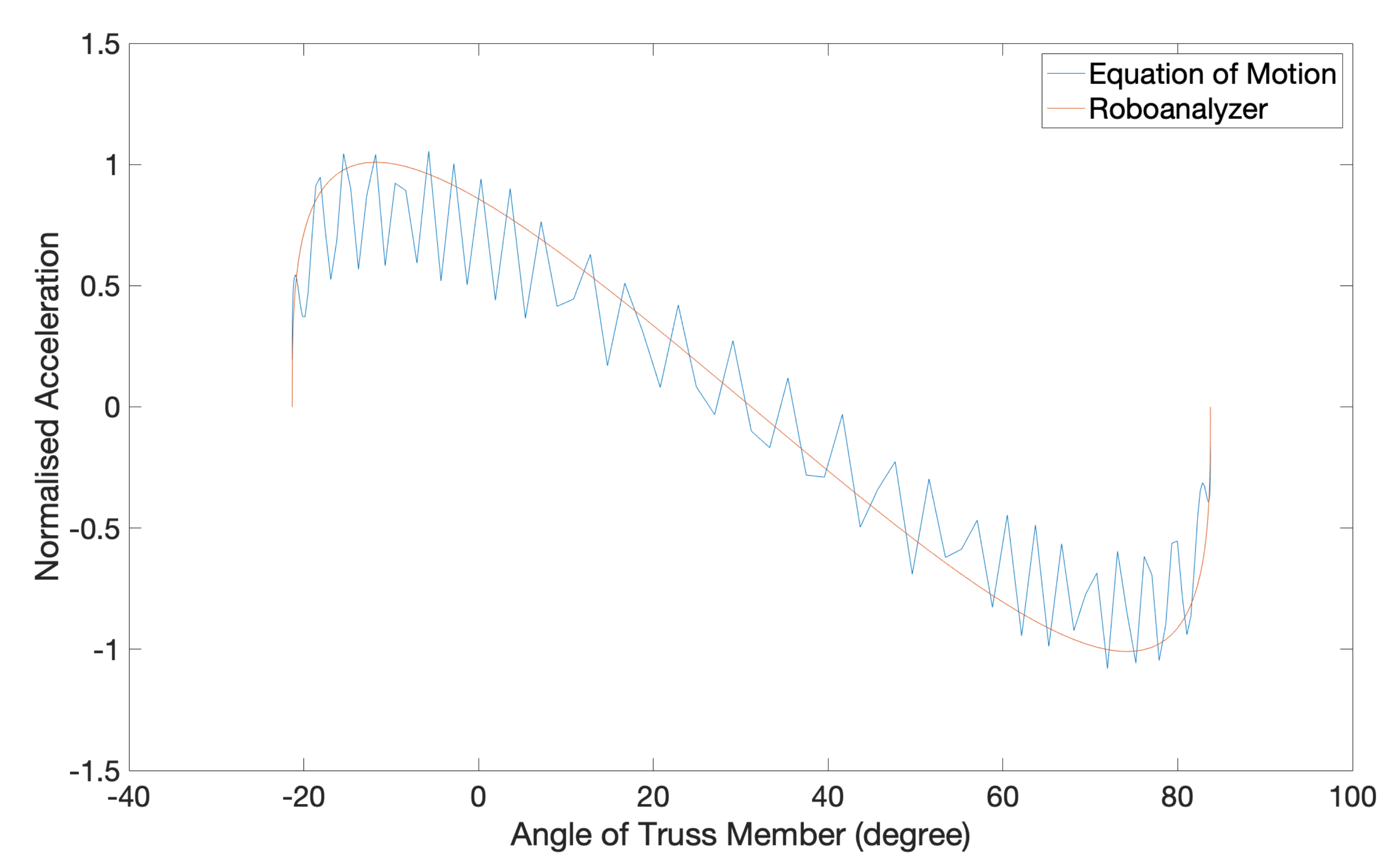
2.3. Stability Computations
2.4. Materials Selection
2.5. Aerodynamic Computations of the Composite Airbrake on Darwin I
2.6. Mechanical Modelling of the Composite Airbrake
3. Results, Analyses and Discussion
3.1. Stability Computations
3.2. Geometrical Design and Actuation
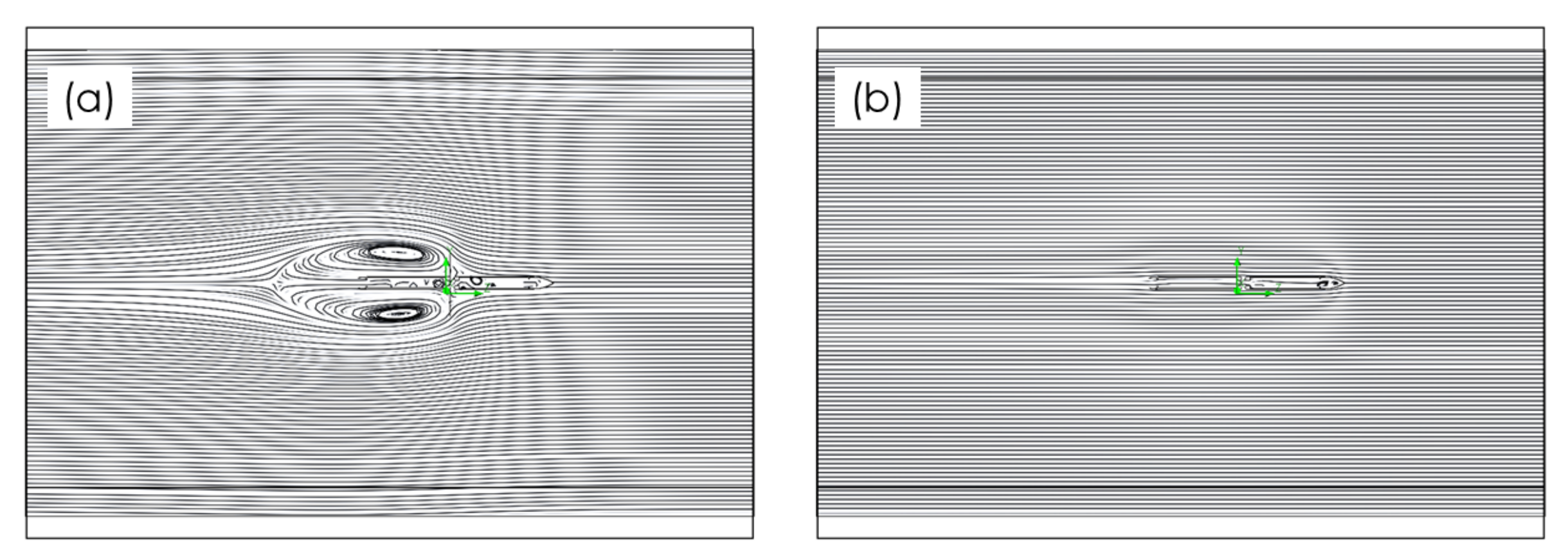
3.3. Aerodynamics
3.4. Materials Selection
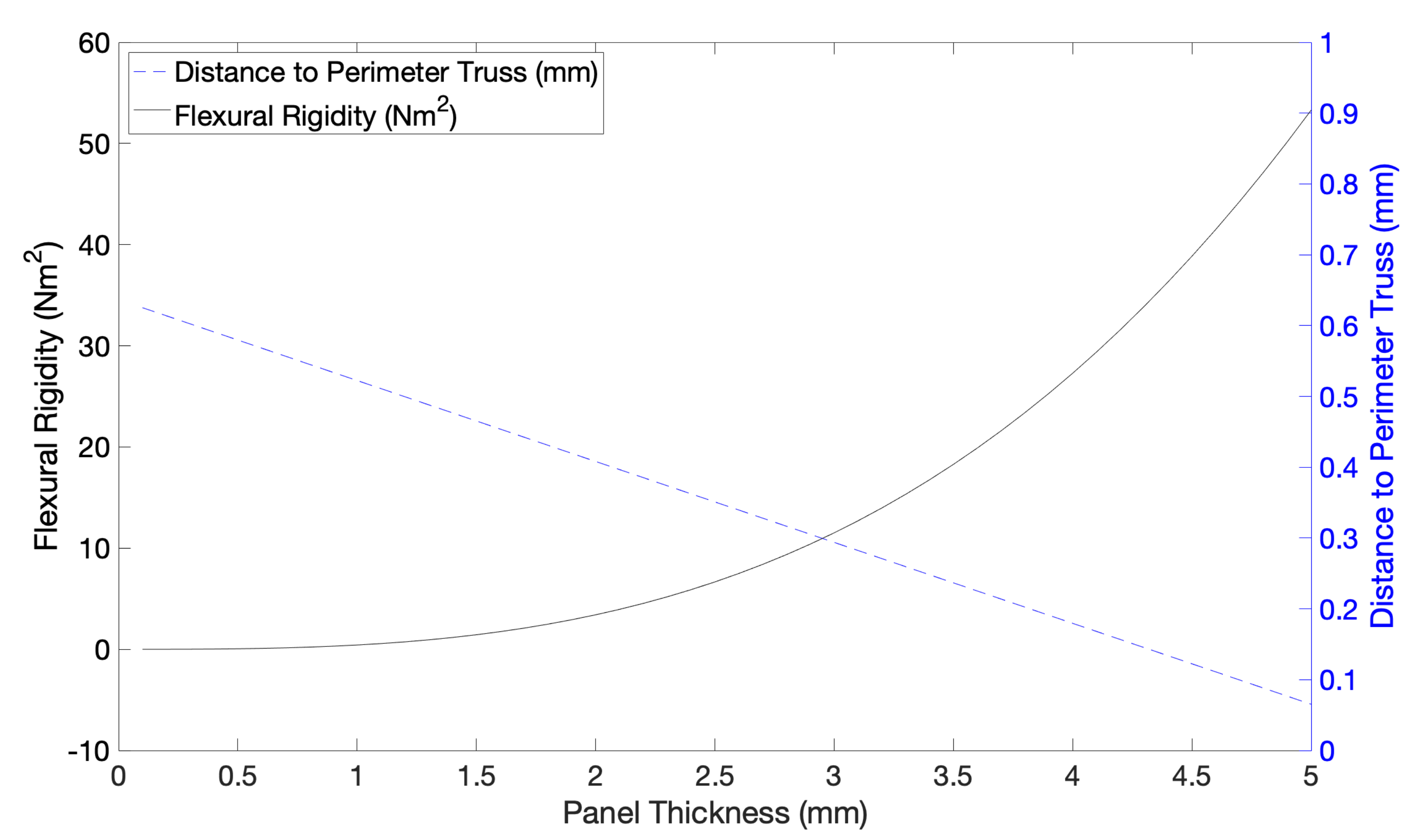
3.5. Thickness Determination of Composite Panels
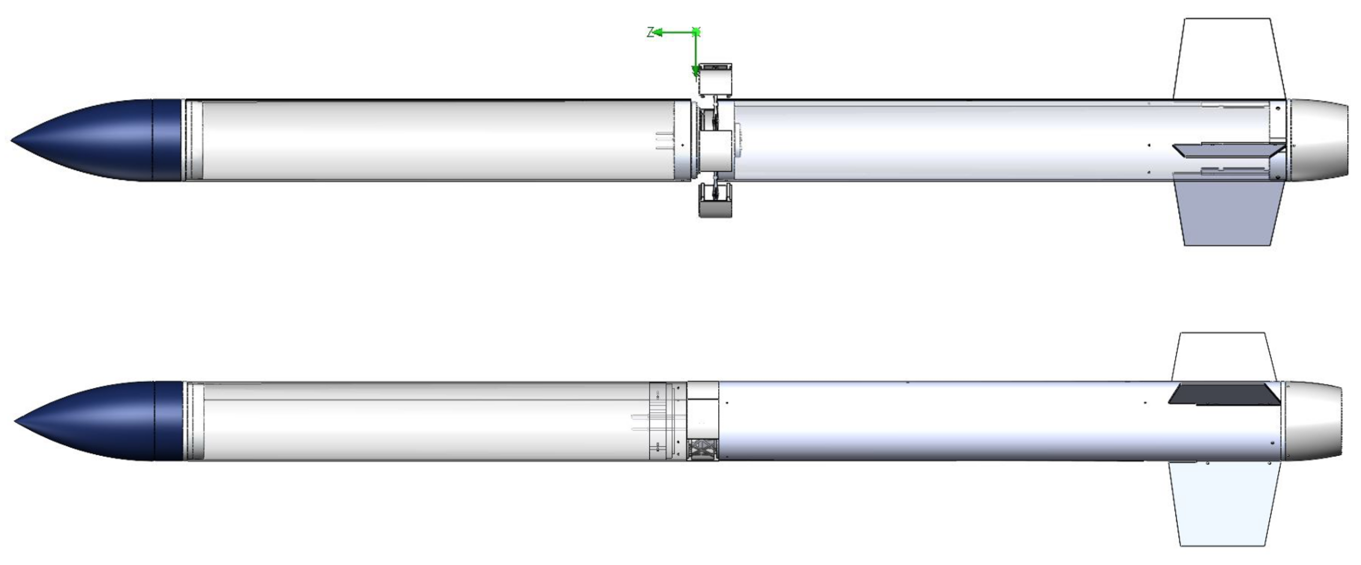
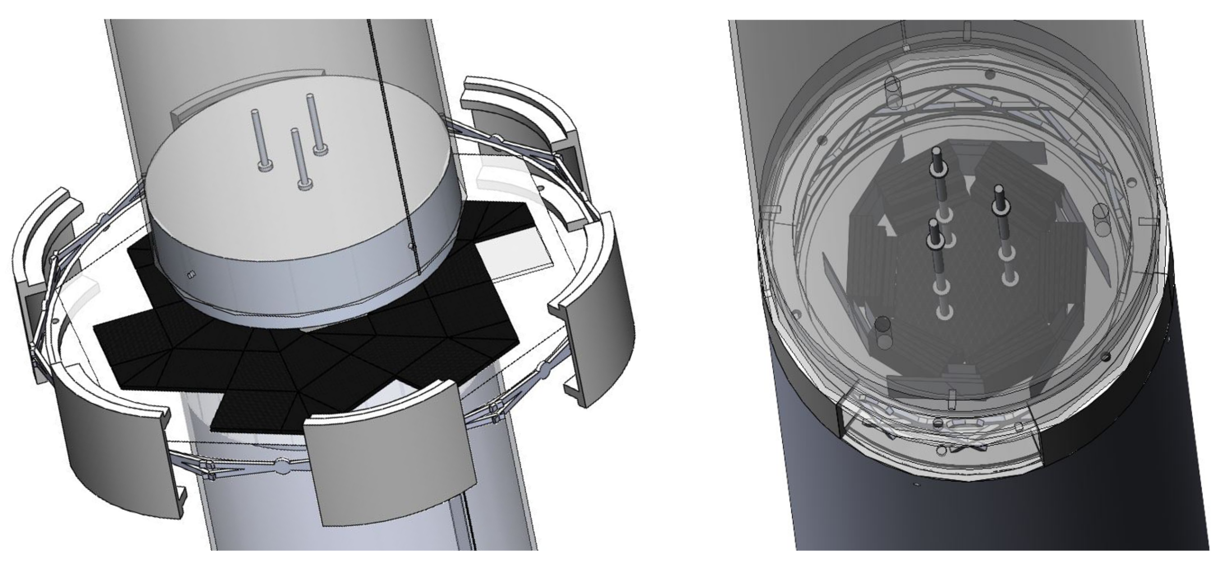
3.6. Darwin I Build Including the Carbon Fibre Composite Origami Airbrake
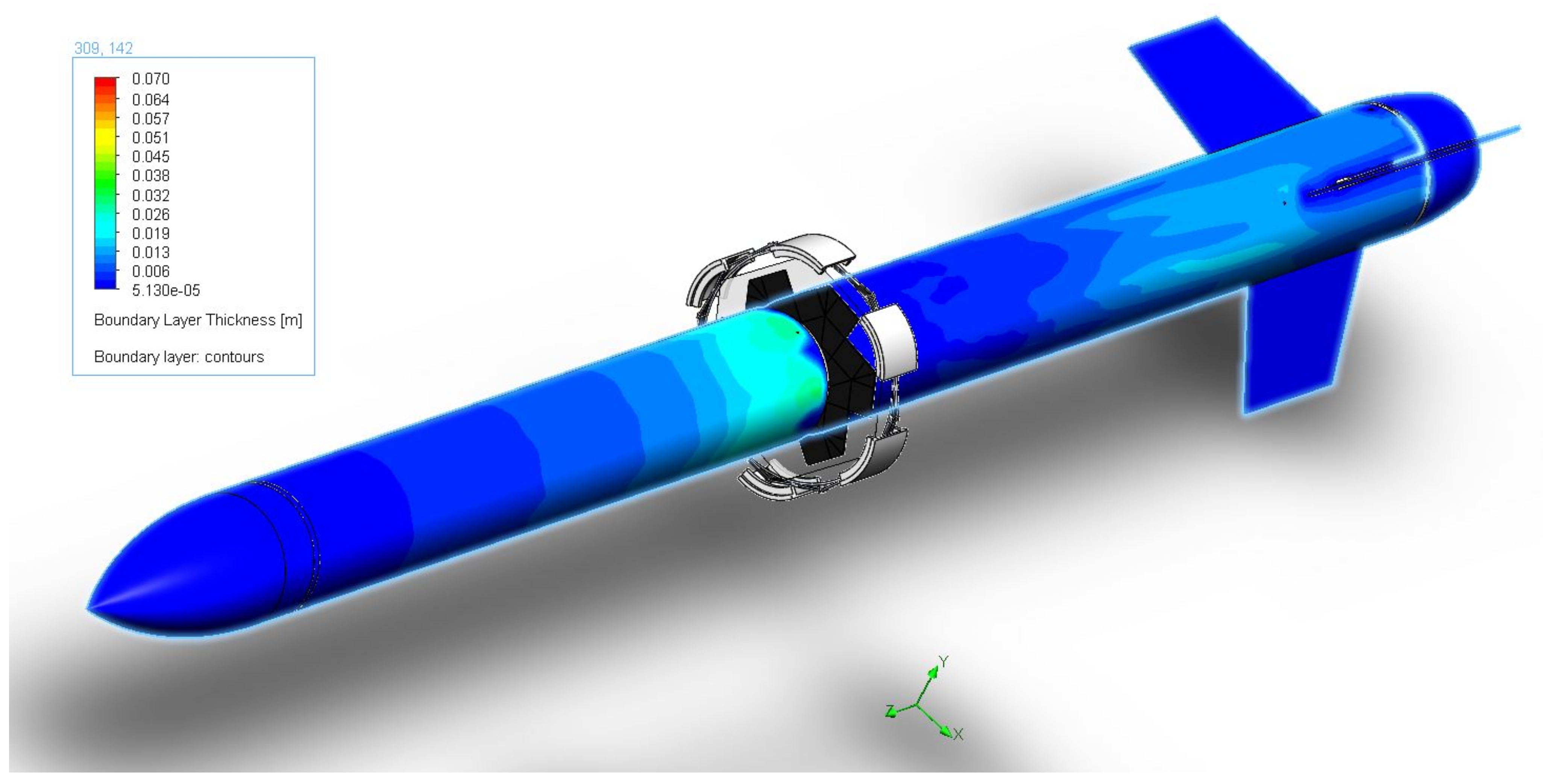
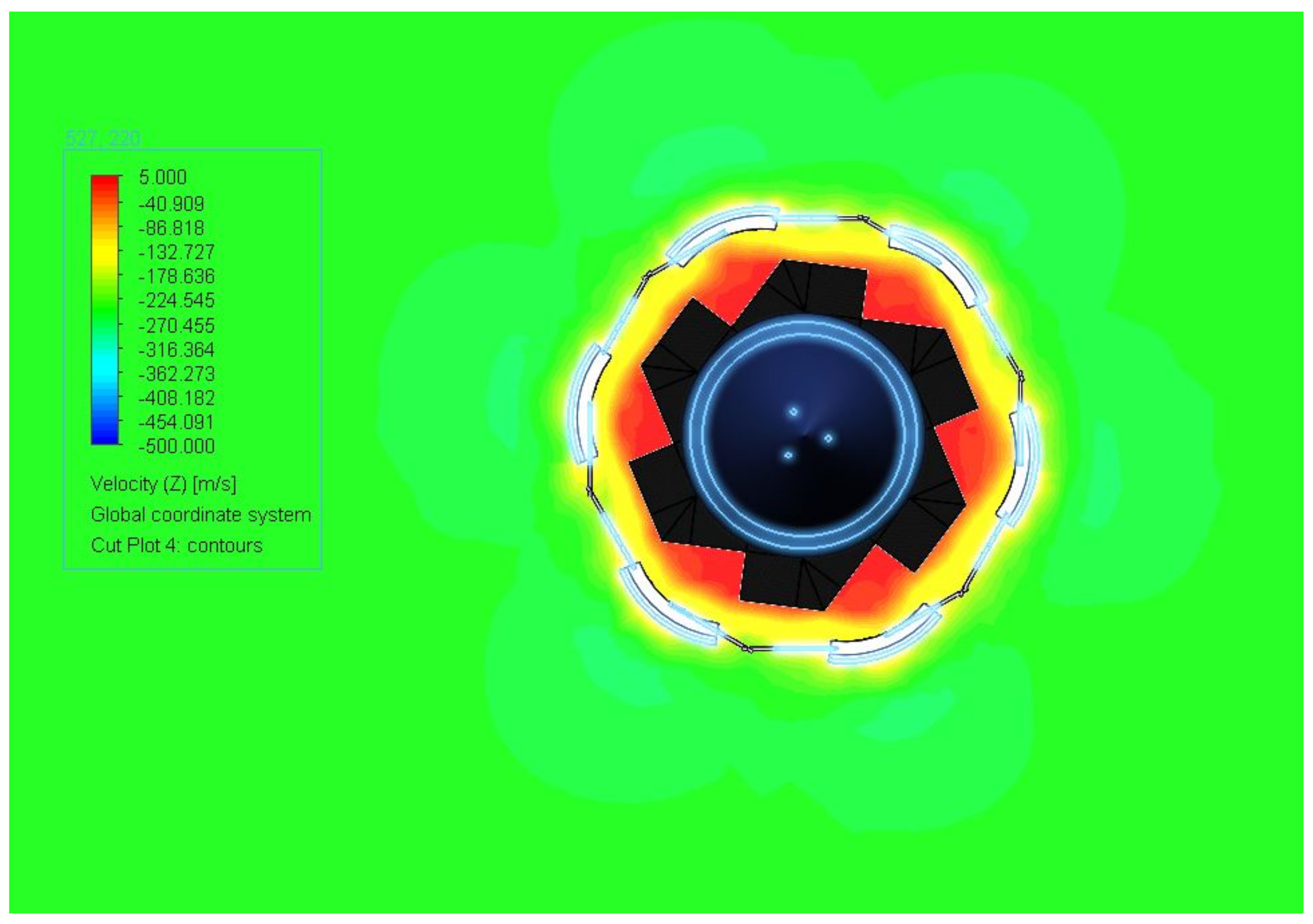
3.7. Aerodynamic Simulations of Darwin I with Airbrake Actuated
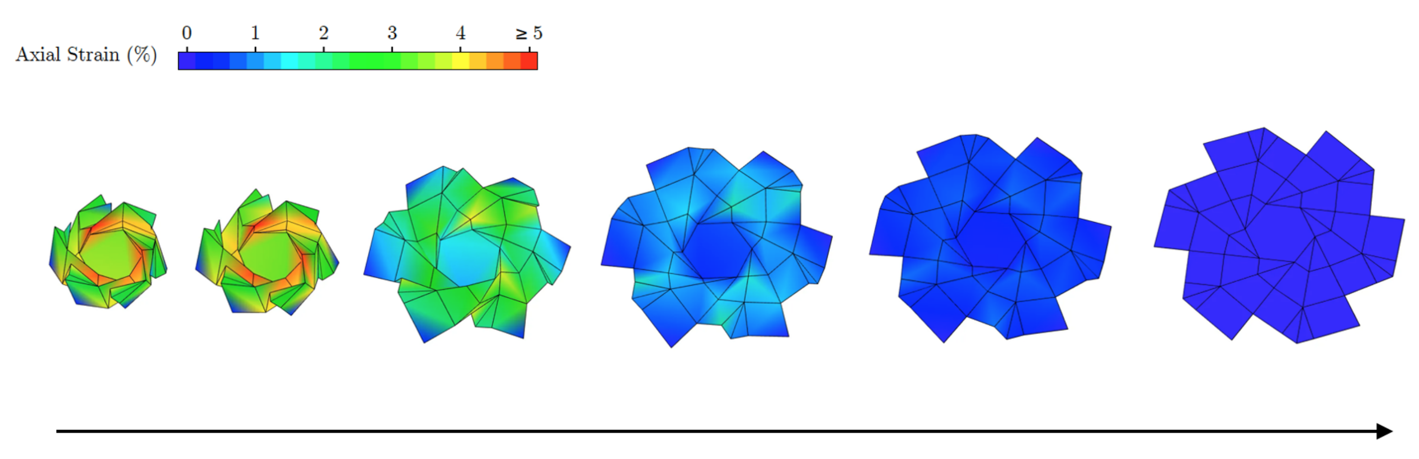
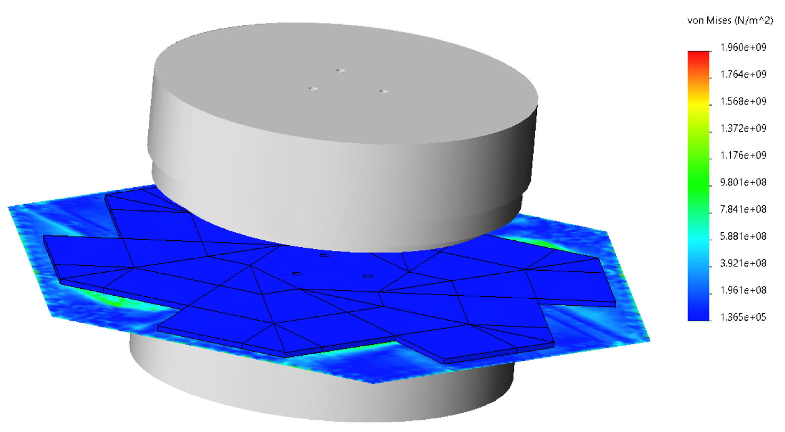
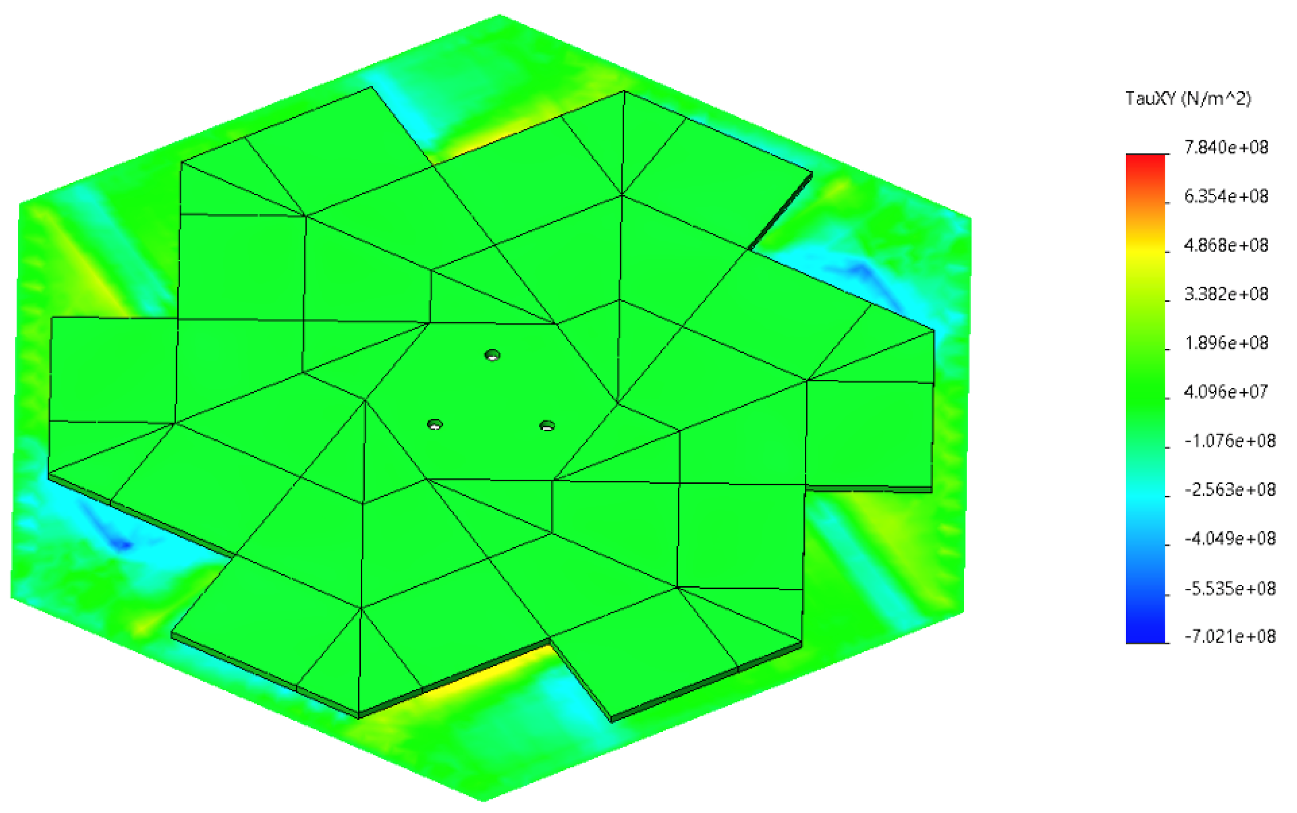
3.8. Continuum Mechanics Simulations of Deployed Composite Airbrake under Drag
4. Conclusions
Author Contributions
Funding
Data Availability Statement
Conflicts of Interest
References
- Niskanen, S. Development of an Open Source Model Rocket Simulation Software. Master’s Thesis, Helsinki University of Technology, Helsinki, Finland, 2009. [Google Scholar]
- Vick, A.R. An Investigation of the Drag Characteristics of Speed Brakes for Mach Numbers from 0.20 to 1.30; National Advisory Committee for Aeronautics: Houston, TX, USA, 1958. [Google Scholar]
- Graziani, A.; Lippert, M.; Uystepruyst, D.; Keirsbulck, L. Scaling and Øow dependencies over forward-facing steps. Int. J. Heat Fluid Flow 2017, 67, 220–229. [Google Scholar] [CrossRef]
- Zh, H.; Fu, S. Forward-facing steps induced transition in a subsonic boundary layer. Sci. China Physics Mech. Astron. 2017, 60, 712. [Google Scholar] [CrossRef]
- Gai, S.L.; Sharma, S.D. Forward-facing steps induced transition in a subsonic boundary layer. Phys. Fluids 1984, 27. [Google Scholar] [CrossRef]
- Bowen, L.A.; Grames, C.L.; Magleby, S.P.; Howell, L.L.; Lang, R.J. A classification of action origami as systems of spherical mechanisms. ASME J. Mech. Des. 2013, 135, 11. [Google Scholar] [CrossRef]
- Bern, M.; Hayes, B. The Complexity of Flat Origami. December 1996. Available online: https://www.osti.gov/biblio/416799 (accessed on 3 February 2021).
- Hernandez, E.A.P.; Hartl, D.J.; Lagoudas, D.C. Active Origami, 1st ed.; Springer International Publishing: Cham, Switzerland, 2019. [Google Scholar]
- Silverberg, J.L.; Evans, A.A.; McLeod, L.; Hayward, R.C.; Hull, T.; Santangelo, C.D.; Cohen, I. Using origami design principles to fold reprogrammable mechanical metamaterials. Science 2014, 345, 647–650. [Google Scholar] [CrossRef] [PubMed]
- Jiang, W.; Ma, H.; Feng, M.; Yan, L.; Wang, J.; Wang, J.; Qu, S. Origami-inspired building block and parametric design for mechanical metamaterials. J. Phys. Appl. Phys. 2016, 49, 315302. [Google Scholar] [CrossRef]
- Kshad, M.; Naguib, H. Characterization of origami shape memory metamaterials (SMMM) made of bio-polymer blends. In Behavior and Mechanics of Multifunctional Materials and Composites 2016; SPIE Digital Library: Bellingham, WA, USA, 2016; p. 98000H. [Google Scholar]
- Boatti, E.; Vasios, N.; Bertoldi, K. Origami Metamaterials for Tunable Thermal Expansion. Adv. Mater. 2017, 29, 1700360. [Google Scholar] [CrossRef]
- Wang, Z.; Jing, L.; Yao, K.; Yang, Y.; Zheng, B.; Soukoulis, C.; Chen, H.; Liu, Y. Origami-Based Reconfigurable Metamaterials for Tunable Chirality. Adv. Mater. 2017, 29, 1700412. [Google Scholar] [CrossRef] [PubMed]
- Lang, R.J.; Tolman, K.A.; Crampton, E.B.; Magleby, S.P.; Howell, L.L. A review of thickness-accommodation techniques in origami-inspired engineering. Appl. Mech. Rev. 2018, 70, 010805. [Google Scholar] [CrossRef]
- Zirbel, S.A.; Lang, R.J.; Thomson, M.W.; Sigel, D.A.; Walkemeyer, P.E.; Trease, B.P.; Magleby, S.P.; Howell, L.L. Accommodating Thickness in Origami-Based Deployable Arrays. ASME J. Mech. Des. 2013, 135, 111005. [Google Scholar] [CrossRef]
- Peraza Hernandez, E.A.; Hartl, D.J.; Lagoudas, D.C. Kinematics of Origami Structures With Smooth Folds. ASME J. Mech. Robot. 2016, 8, 061019. [Google Scholar] [CrossRef]
- Vaidyanathan, R. Kirk-Othmer Encyclopedia of Chemical Technology, 4th ed.; John Wiley and Sons, Inc.: Hoboken, NJ, USA, 2000; Volume 21, pp. 776–962. [Google Scholar]
- Wood, L.J.; Rendon, J.; Malak, R.J.; Hartl, D. An origami-inspired, sma actuated lifting structure. In Proceedings of the ASME 2016 International Design Engineering Technical Conferences and Computers and Information in Engineering Conference, Charlotte, NC, USA, 21–24 August 2016. [Google Scholar]
- Faist, K.A.; Wiens, G.J. Parametric study on the use of hoberman mechanisms for reconÆgurable antenna and solar arrays. In Proceedings of the 2010 IEEE Aerospace Conference, Big Sky, MT, USA, 6–13 March 2010; pp. 1–8. [Google Scholar]
- Zirbel, S.A.; Trease, B.; Magleby, S.; Howell, L. Deployment methods for an origami-inspired rigid-foldable array. In Proceedings of the 42nd Aerospace Mechanism Symposium, Baltimore, MD, USA, 1 May 2014. [Google Scholar]
- Mitani, J. Oripa: Origami Pattern Editor. 2012. Available online: https://mitani.cs.tsukuba.ac.jp/oripa/ (accessed on 24 April 2021).
- Tachi, T. Origami Software. 2020. Available online: https://origami.c.u-tokyo.ac.jp/%5C~%7B%7Dtachi/software/ (accessed on 24 April 2021).
- Cylindrical Roller Bearings. Available online: https://www.skf.com/uk/products/rolling-bearings/roller-bearings/cylindrical-roller-bearings (accessed on 3 February 2021).
- Gupta, V.; Chittawadigi, R.G.; Saha, S.K. RoboAnalyzer: Robot Visualization Software for Robot Technicians. In Proceedings of the Advances in Robotics (AIR’17), New Delhi, India, 28 June–2 July 2017; pp. 1–5. [Google Scholar]
- Lagrange, J. Analytical Mechanics; Springer Science and Business Media: Dordrecht, The Netherlands, 2013. [Google Scholar]
- RS Pro Stainless Steel Extension Spring, 22.1 mm × 3.2 mm. Available online: https://uk.rsonline.com/web/p/extension-springs/0821419/ (accessed on 24 April 2021).
- Eksi, S.; Genel, K. Comparison of mechanical properties of unidirectional and wovencarbon, glass and aramid Æber reinforced epoxy composites. Acta Phys. Pol. 2017, 132, 879–882. [Google Scholar] [CrossRef]
- 6082-t6 t651 Plate. 2021. Available online: https://www.aalco.co.uk/datasheets/Aluminium-Alloy_6082-T6~T651_148.ashx (accessed on 24 April 2021).
- Density of CFRP. Available online: https://www.easycomposites.co.uk/high-strength-carbon-fibre-sheet (accessed on 24 April 2021).
- Arao, Y.; Koyanagi, J.; Utsunomiya, S.; Takeda, S.; Kawada, H. Analysis of time-dependent deformation of a CFRP mirror under hot and humid conditions. Mech. Time-Depend. Mater. 2009, 13, 183–197. [Google Scholar] [CrossRef]
- Torayca t300 Fibre Data Sheet. Available online: https://media.easycomposites.co.uk/datasheets/T300DataSheet.pdf (accessed on 24 April 2021).
- Hamad, A. Size and shape effect of specimen on the compressive strength of HPLWFC reinforced with glass fibres. J. King Saud Univ. Eng. Sci. 2017, 29, 373–380. [Google Scholar] [CrossRef]
- Aamir, M.; Tolouei-Rad, M.; Giasin, K.; Nosrati, A. Recent advances in drilling of carbon fiber reinforced polymers for aerospace applications: A review. Int. J. Adv. Manuf. Technol. 2019, 105, 2289–2308. [Google Scholar] [CrossRef]
- Abdelal, G.; Barbero, E.; Robotham, A. Fatigue damage of composite structures applying a micromechanical approach. In Proceedings of the AES-ATEMA 2011 International Conference on Advances and Trends in Engineering Materials and their Applications, Milan, Italy, 4–8 July 2011. [Google Scholar]


| Parameter | Value |
|---|---|
| Initial coasting velocity | 247.5 m/s |
| Initial coasting altitude | 1200 m |
| Initial coasting acceleration | −19.52 m/s |
| Length of rocket | 2.18 m |
| Mass of rocket | 18.4 kg |
| Diameter of rocket | 0.145 m |
| Target apogee | 3048 m (10,000 ft) |
| Reynolds Number | 3.21 × 10 |
| Mach Number | 0.678 |
| Stiffness | Strength | Shear Modulus |
|---|---|---|
| Material | Density (kg/m) | Young’s Modulus (GPa) | Failure Strength (MPa) |
|---|---|---|---|
| Aluminium 6082-T6 | 2700 | 70 | 300 |
| CFRP (quasi-isotropic) | 1269 | 113.5 | 644 |
| GFRP (Uni-directional) | 1550 | 18.3 | 432 |
| Carbon fibre (Woven) | 1760 | 230 (Tensile) | 3530 (Tensile) |
| Glass fibre (Woven) | 2680 | 72 | 1700 |
| Dimension | Value |
|---|---|
| Base hexagon side length (a) | 29.12 mm |
| Height of panel adjacent to base hexagon (x) | 16.81 mm |
| Hypotenuse of panel adjacent to base hexagon (y) | 58.24 mm |
| Folded height | 33.62 mm |
| Unfolded diameter | 210 mm |
| Exposed area () | 18,100 mm (0.0181 m) |
| Thickness (t) | 3 mm (0.0003 m) |
| Parameter | Value |
|---|---|
| Pressure (kPa) | 89.540 |
| Dynamic pressure (kPa) | 32.855 |
| Density (fluid) (kg/m) | 1.102 |
| Mach number | 0.712 |
| Turbulence intensity (%) | 4.231 |
| Dynamic viscosity ( Pa s) | 1.763 |
| Prandtl number | 0.708 |
Publisher’s Note: MDPI stays neutral with regard to jurisdictional claims in published maps and institutional affiliations. |
© 2021 by the authors. Licensee MDPI, Basel, Switzerland. This article is an open access article distributed under the terms and conditions of the Creative Commons Attribution (CC BY) license (https://creativecommons.org/licenses/by/4.0/).
Share and Cite
Lee, H.; Alam, P. The Design of Carbon Fibre Composite Origami Airbrakes for Endeavour’s Darwin I Rocket. J. Compos. Sci. 2021, 5, 147. https://doi.org/10.3390/jcs5060147
Lee H, Alam P. The Design of Carbon Fibre Composite Origami Airbrakes for Endeavour’s Darwin I Rocket. Journal of Composites Science. 2021; 5(6):147. https://doi.org/10.3390/jcs5060147
Chicago/Turabian StyleLee, Hyeon (Ann), and Parvez Alam. 2021. "The Design of Carbon Fibre Composite Origami Airbrakes for Endeavour’s Darwin I Rocket" Journal of Composites Science 5, no. 6: 147. https://doi.org/10.3390/jcs5060147
APA StyleLee, H., & Alam, P. (2021). The Design of Carbon Fibre Composite Origami Airbrakes for Endeavour’s Darwin I Rocket. Journal of Composites Science, 5(6), 147. https://doi.org/10.3390/jcs5060147