1. Introduction
Fibre reinforced composite materials are increasingly used in many applications, mainly in the aerospace industry, and the need of maintenance and repair is of main concern for both the manufacturers and the end-users. Multi-layered composite structures are susceptible to shear and peel stresses along the interface between the laminate. When damage occurs, a repair is needed in order to stop the damage propagation and restore as much of the strength and stiffness as possible.
It is proven that adhesively bonded repairs are more effective than bolted repairs in composite materials, as they allow a more uniform load transfer without inducing stress concentrations [
1]. Composite materials’ bonding has been extensively researched using numerical or experimental models [
2,
3,
4,
5,
6] with various joint configurations: uniform lap, stepped lap, scarf or stepped scarf. In the latter, which is the focus of this work, the stepped scarf repair was studied, as this method is more attractive to the aerospace industry. Also, scarf repairs are more efficient than lap repairs, because the former have in general higher strength and can be used to bond thin, as well as thick adherends. Depending on certain conditions, though, stepped scarf repairs are more easily applied. However, they exhibit a higher stress concentration along the corners of each step [
7].
In the relevant literature, a few analytical approaches have been attempted regarding scarf repairs. It has been proven that in stepped-scarf joints the stress distribution is non-uniform when dissimilar adherends are bonded together. Lubkin was the first who studied the effect of the adherends’ stiffnesses to the scarf angle. Nonetheless, the angles that he predicted were so big that they cannot be practically applied in aerospace applications [
8]. Moreover, a remarkable conclusion is that there is a stress concentration at the edge of the more compliant adherend [
9,
10]. Later, Hart-Smith mathematically analysed the stress distribution for stepped scarf repairs taking into account potential adherend stiffness dissimilarity and thermal mismatch [
11].
An experimental research [
12] evaluated how several parameters, namely type of material, temperature, moisture and the scarf’s geometry influence the failure load. An important observation from this study was that the increase of the scarf angle gradually decreases the ultimate load bearing capacity. More specifically, it has been proven that only scarf angles less than 2° will result in the laminate failing outside the repaired region [
13]. However, these results have no practical interest, as such extended patches are not applicable. Baker et al. [
14] observed strain concertation in the repair doubler plied above the top end of the scarf aluminium honeycomb sandwich beam specimens. This conclusion was compatible with the FE models.
Gunnion and Herszberg [
15] conducted a parametric study using finite element models to investigate the sensitivity of normal and shear stress distribution of scarf repaired laminates, subjected to tensile loading, to joint performance parameters. They were mainly focused on the geometry’s parameters, including the stacking sequence, the adhesive and laminate thickness, the scarf angle, the number of over-plies and the effect of mismatched adherend lay-ups. One of their most relevant conclusions was that the addition of an overply can dramatically decrease the peak stresses and that the integrity of a repaired laminate is not sensitive to the patch’s lay-up. However, the analysis was conducted in two-dimensional models and nonlinear behaviour was not considered for the adhesive. Hence, stresses in the width direction were assumed to be constant [
16].
More recently, Bendemra et al. reached the same conclusion [
17]. Another two-dimensional linear analysis [
18] has been carried out in five tensile loaded quasi- isotropic repaired plates with scarf angles ranging from 1.1° to 9.2° to compare the shear stress distribution along the adhesive. Failure loads were obtained using a number of different failure criteria each time. Kumar et al. [
13] experimentally investigated the failure modes of scarf repaired laminates in uniaxial tension with angles that were varying from 0° to 5°. It was concluded that the plates with a scarf angle below 2° failed due to fibre fracture, while those with a scarf angle above 2° failed due to shear stresses in the adhesive between the repair patch and the laminate. These results came to agreement with the corresponding three-dimensional linear elastic FE models. In this study the adhesive was assumed to be perfectly bonded to the parent adherend. Tzetzis and Hogg [
19] examined the tensile failure modes and failure loads in vacuum-assisted resin infused repairs for three different scarf angles. A parametric stress and failure numerical study was performed in two-dimensional repaired laminates with different scarf angles and stacking sequences [
20] by Campilho. In this non-linear analysis, cohesive damage models were used in order to better simulate the behaviour between the adherent and the repair patch. One of the findings was that the fracture properties of the adhesive do not influence the strength of the repaired laminate, whereas the mechanical properties governed its behaviour. Campilho et al. [
21] also used cohesive damage models in order to predict the behaviour of CFRP plates under tensile loading. The majority of the studies take into consideration only the cohesive interaction between the patch and the parent laminate and not between the plies. Also, there is a limited number of studies that examined stepped scarf repaired laminates that are subjected in compressive loading.
In this investigation the effectiveness of stepped repair to damaged fibre reinforced composite materials was investigated by using previously validated FE numerical models [
22]. A parametric study was conducted in order to evaluate the influence of the scarf ratio to the integrity of the repaired laminate and the stiffness restoration of the laminate. Non-elastic behaviour was assumed for both the repaired laminate and the adhesive between the laminate and the repair patch. Also, all numerical models considered the shear stresses between the layers and the Hashin’s damage criteria were used [
23].
2. Materials and Methods
Abaqus CAE was used for the modelling of the laminate made of IMS 24K 997-2, taking into account the actual strength (Hashin damage) with properties as listed in
Table 1. Several parametric numerical models with different scarf ratios were developed. The repaired laminate was analyzed with and without sub laminates, taking into account the actual strength of each layer (Hashin damage). The creation of the models was based on FE models of a previous study [
22] where the FE models were validated against three different types of tests; double lap shear tests, Compression After Impact (CAI) standard tests and Stepped scarf repaired coupon tensile tests. This way the models were capable of capturing the lamina behavior, the bonding strength and the patch performance. Parametric non-linear analysis was performed, using 8-node continuum shell elements with a mesh size of 1 mm, that have displacement degrees of freedom, resulting in models with one hundred and fifty thousand elements. Also, FE models were created with different scarf ratios, varying from 20 to 240.
More specifically, 5 models, whose repair patch has the same number of steps as the layers of the base laminate, were analyzed with scarf ratios varying between 20, 30, 40, 50 and 60. Then, another 3 models, whose repair patch has 4 steps in total were examined with scarf ratios 30, 60 and 120. And finally, 4 additional models whose repair patch has 3 steps, were analyzed. Scarf ratio is defined as the length of the step divided by the height of each step,
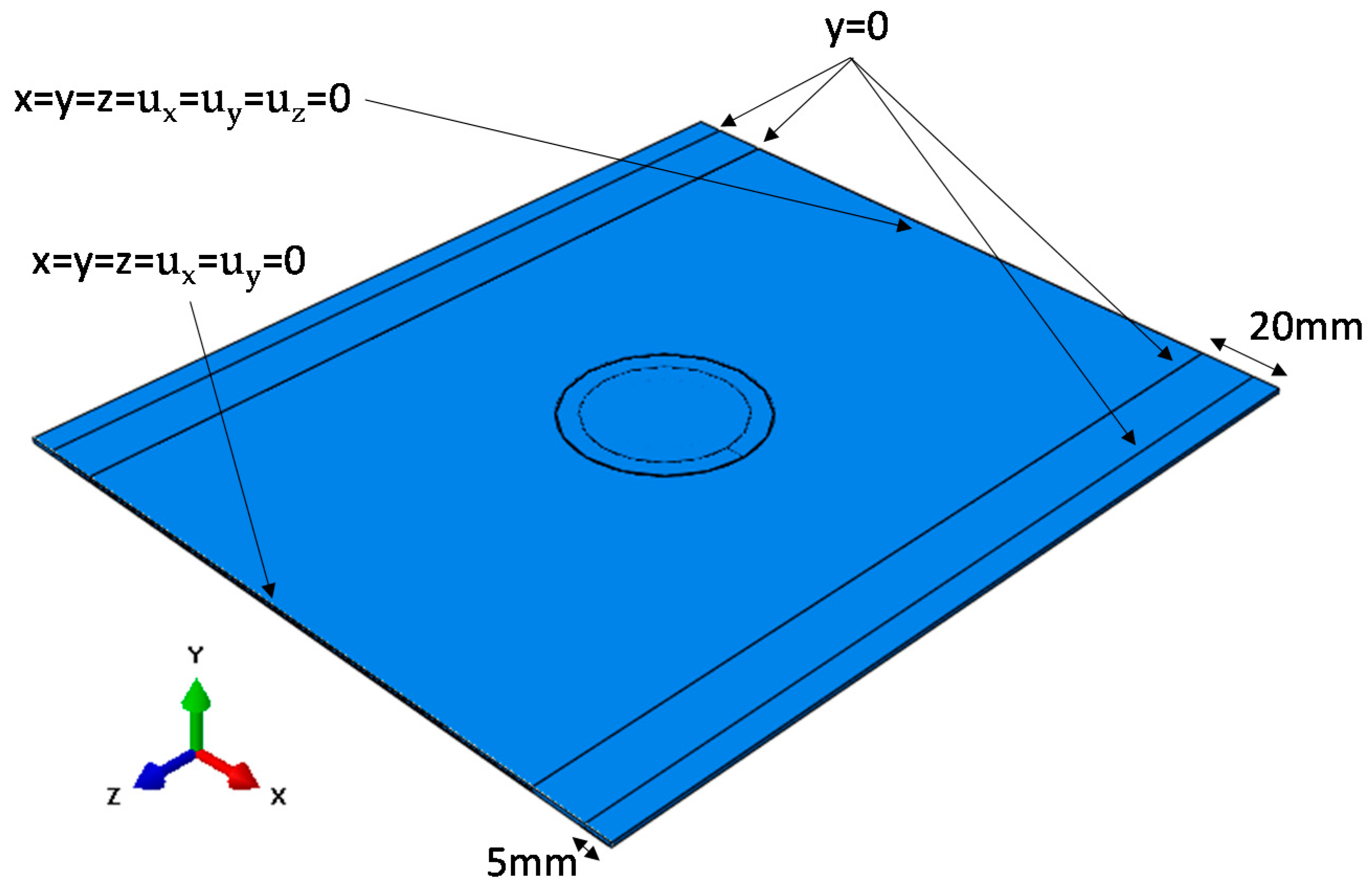
. All models were subjected in maximum compressive displacement of 1.3 mm via this top clamp, which was set to be in tie constraint with the laminate. Boundary conditions were applied similar to what the AITM1-0010 standard indicates. In particular, one of the short sides of the plates was encastred, while the other was able to move only on the Z-axis. Also, eight rods in total were placed onto the upper and bottom face of the laminate (4 at the upper and 4 at the bottom face) in the direction of the applied compression load, and in order to prevent buckling (
Figure 1).
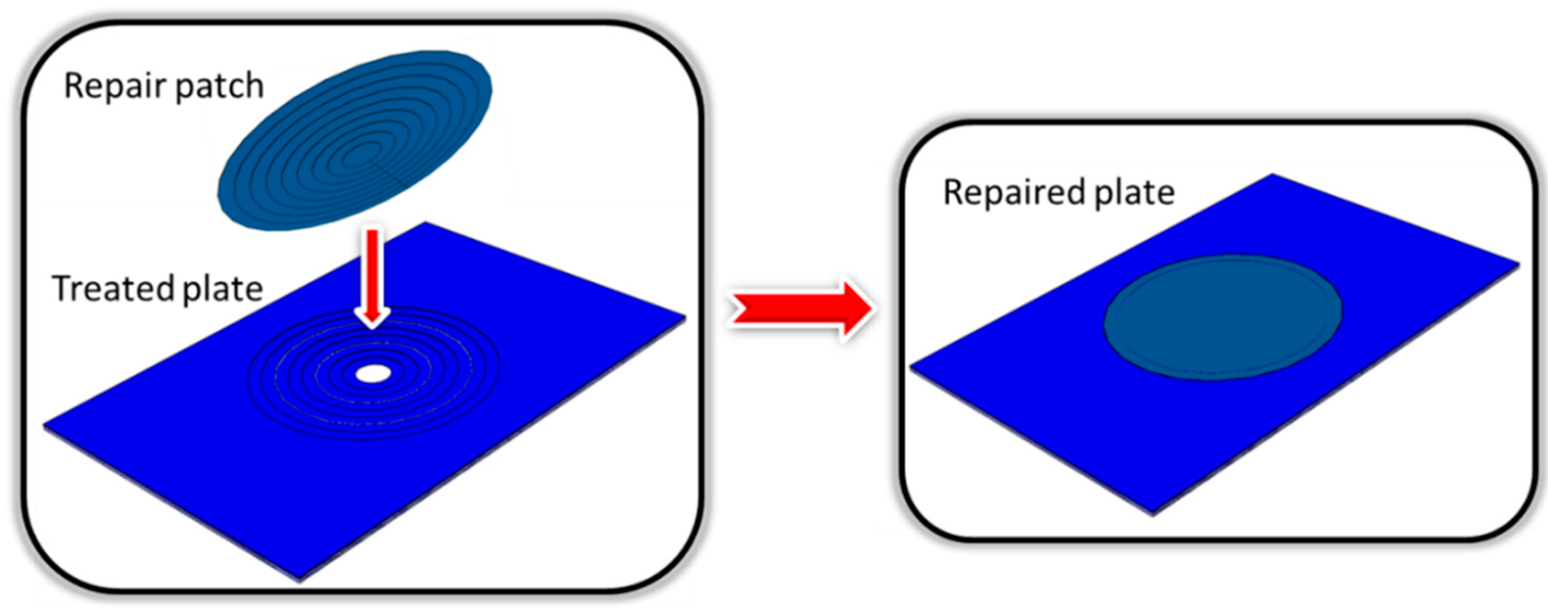
Table 2 shows the geometrical characteristics of the repaired laminate. It was assumed that the lower layer of the plate had circular damage with a 10 mm diameter. Then, material was gradually removed in layers from the laminate. Each layer that was removed had the same thickness as the thickness of each ply of the base laminate. Afterwards, the circular repair patch was designed to perfectly fit onto the plate in the region where the material was previously removed. The material and the lay-up of the patch were the same with those of the base laminate in order to achieve the maximum strength and the restoration of the properties of the undamaged laminate (
Figure 2).
Initially, five repaired plates with scarf ratios: 20, 30, 40, 50 and 60 and one damaged plate with a 10 mm diameter through hole were analyzed in order to compare their response and evaluate the stiffness and strength restoration for each case.
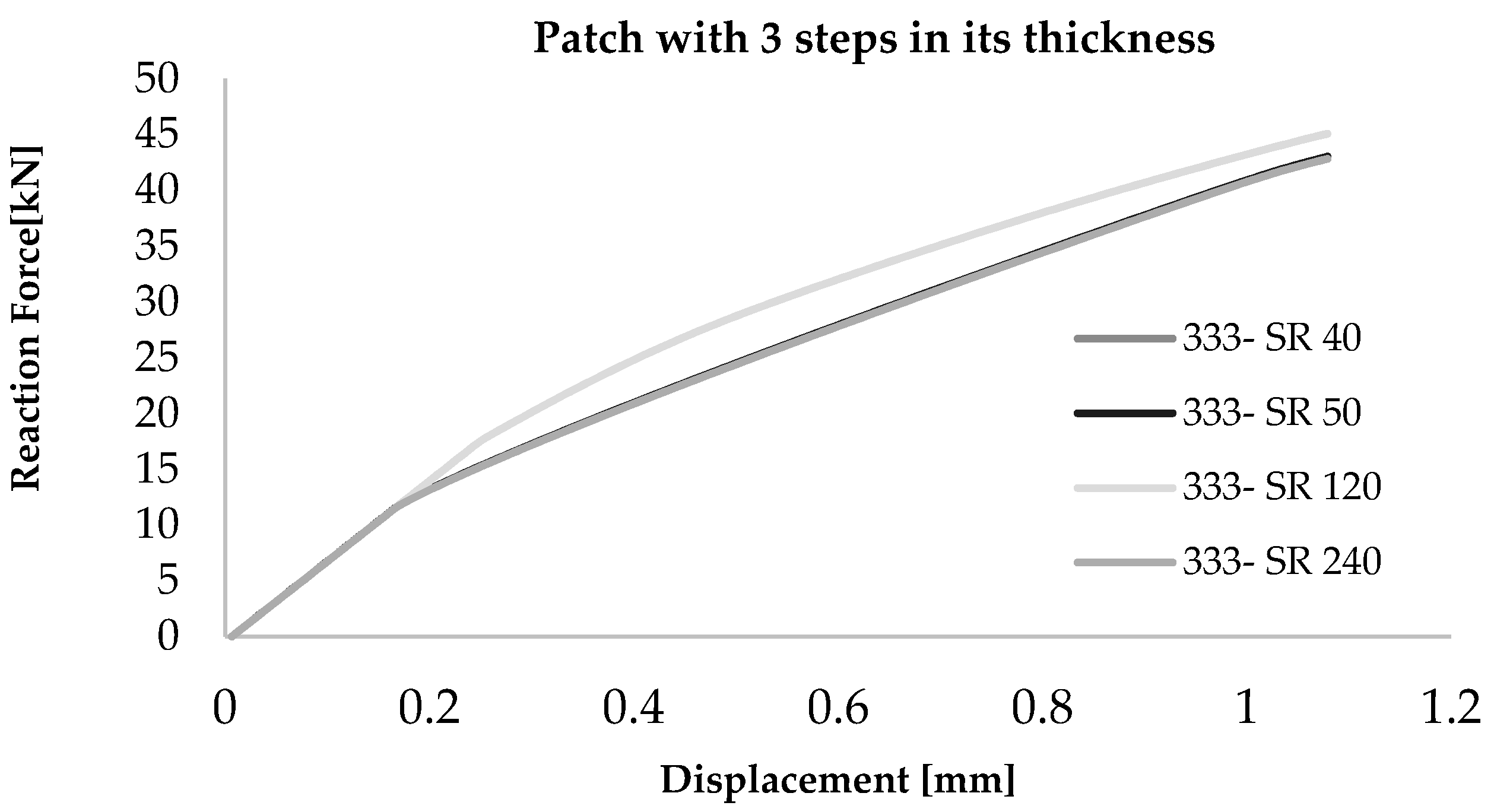
Then, in order to evaluate the effect of the step number compared to the number of the plies that constitute the base 9-ply plate, two scenarios were investigated. In the first scenario, the 30, 60 and 120 scarf ratios were analyzed in plates where the patch had four steps in its thickness and not one step for each of the nine plies. The first three steps corresponded to two plies of the laminate, whereas the last step corresponded to one ply. So, these series of modelled repaired laminates are being abbreviated as 2221. In the second scenario, the patches had scarf ratios of 40, 50, 120 and 240 and three steps in their thickness. They are referred as 333 patches as each step of the patch is being bonded with three plies of the laminate. Anisotropic behavior of the laminate was taken into consideration. For each ply, the lamina properties measured in house and are shown in
Table 1.
The repair patch was bonded onto the parent laminate. To simulate this bonding, cohesive interaction, which is defined as a surface interaction property, was applied in each step between the repair patch and the base laminate, as previously studied and validated [
22]. The cohesive properties have been calculated as a function of the mix-mode ratios, that are defined as the relative proportion of normal to shear displacements at the cohesive zone, and the Mixed mode coefficient (Benzeggagh-Kenane criterion) was set to the value of 2. Uncoupled traction-separation behaviour was taken into account, so that contact penalties enforce the cohesive constraint in normal and in tangential direction. Off-diagonal terms in the elasticity matrix were set to zero. The values of the fracture energies, the nominal traction stresses and the penalty stiffnesses that were utilized are shown in
Table 3.
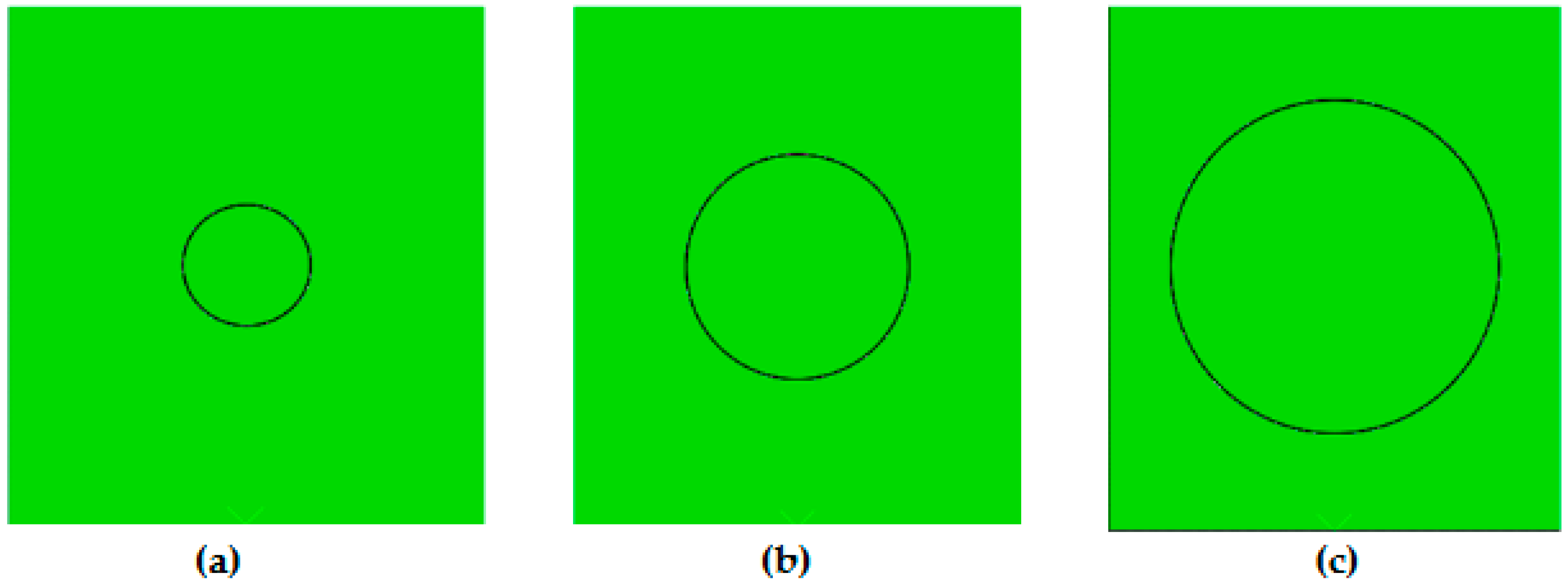
The interfacial failure is driven by the progressive degradation of the cohesive layer stiffness. The damage modelling was defined using a damage initiation criterion and a damage evolution law. Initially the response was assumed to be linear until the maximum stress criterion was satisfied. Then, the rate of the stiffness degradation was described from the power law criterion that was defined using the fracture energy in mode I, II and III. The power law dictates failure in the normal or tangential mode and that failure is generated by an equation that takes into account both the normal and shear fracture energies. A schematic of the repair sizes is shown in
Figure 3 where the size of the 20, 40 and 60 patches are being compared.
3. Results
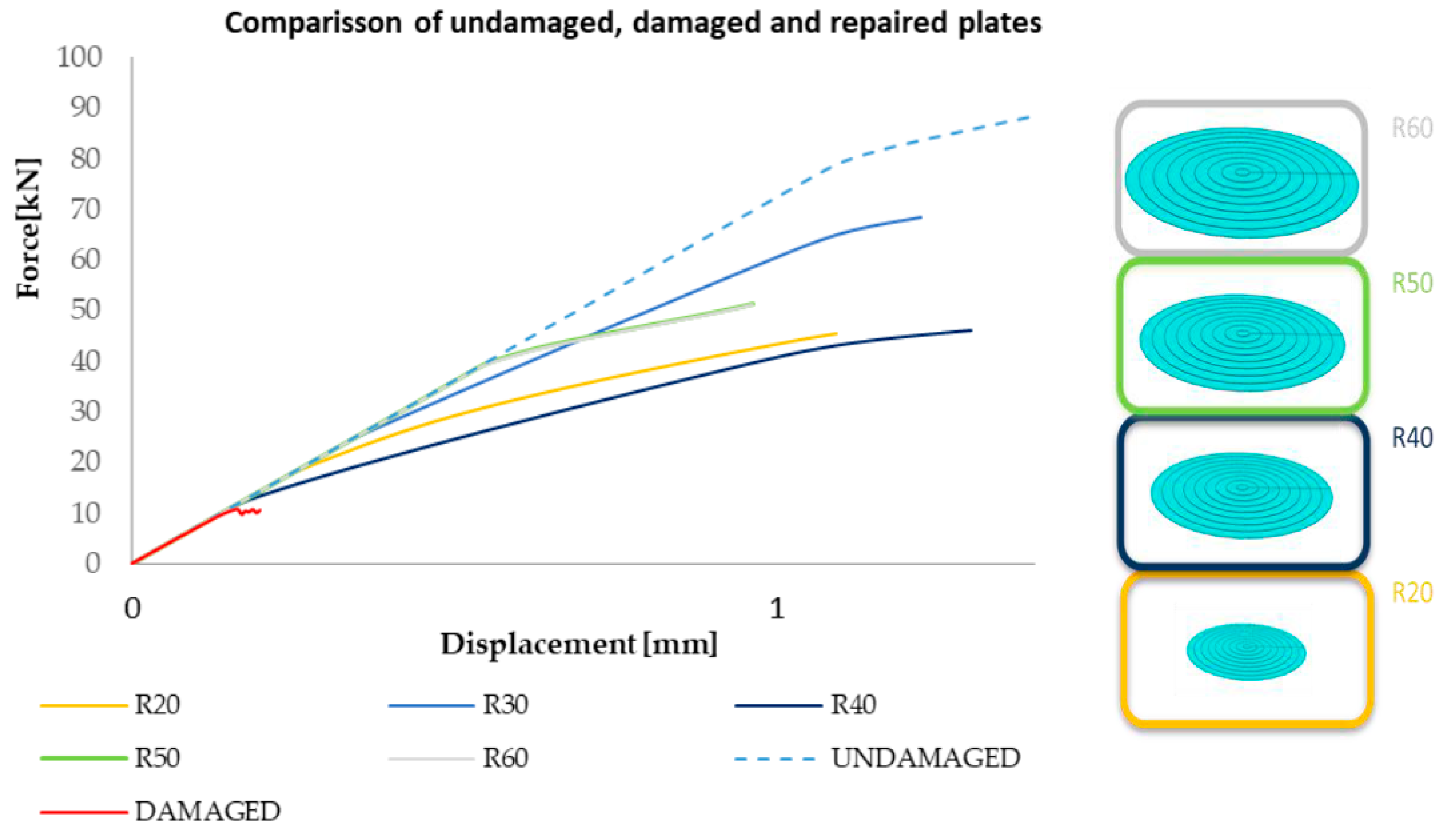
A graphical representation of the mechanical behavior of the repaired laminates as predicted by the FEA is given in
Figure 4, together with those of the undamaged base laminate and the damaged laminate with the 10 mm through hole. The patches with scarf ratio 50 and 60 had a similar response, as their curves practically coincide.
The maximum compressive force that the undamaged plate can withstand, just prior to buckling, is 80 kN, while for the damaged plate this force is less than 10 kN. Regarding the repaired plates, the highest load before buckling corresponds to the repair cases with 50 and 60 scarf ratios and is about 40 kN. The plate with scarf ratio 20 had sufficiently lower buckling load at 17.5 kN. Finally, the repaired laminate with 40 scarf ratio showed a lower buckling load of 12.5 kN. However, by examining the patch with scarf ratio 40, it is remarkable that it was the less effective one, even compared to the patches with 20 ratio. This can be justified since the buckling load is affected by the different buckling modes. So, the response of the repaired laminate cannot be fully anticipated based on the scarf ratio since different buckling modes could introduce earlier deformations. Nevertheless, it is evident that the final failure load can be increased by increasing the scarf ratio up to a threshold value, which is 40 kN, where no significant difference can be observed. So, applying a repair is vital as a repaired laminate could have 5 times higher compressive strength compared to the strength of the damaged laminate. However, the repair could only restore up to 50% of the buckling load of the undamaged plate.
Table 4 summarizes the results presented above and correspond to the global buckling load of the laminate.
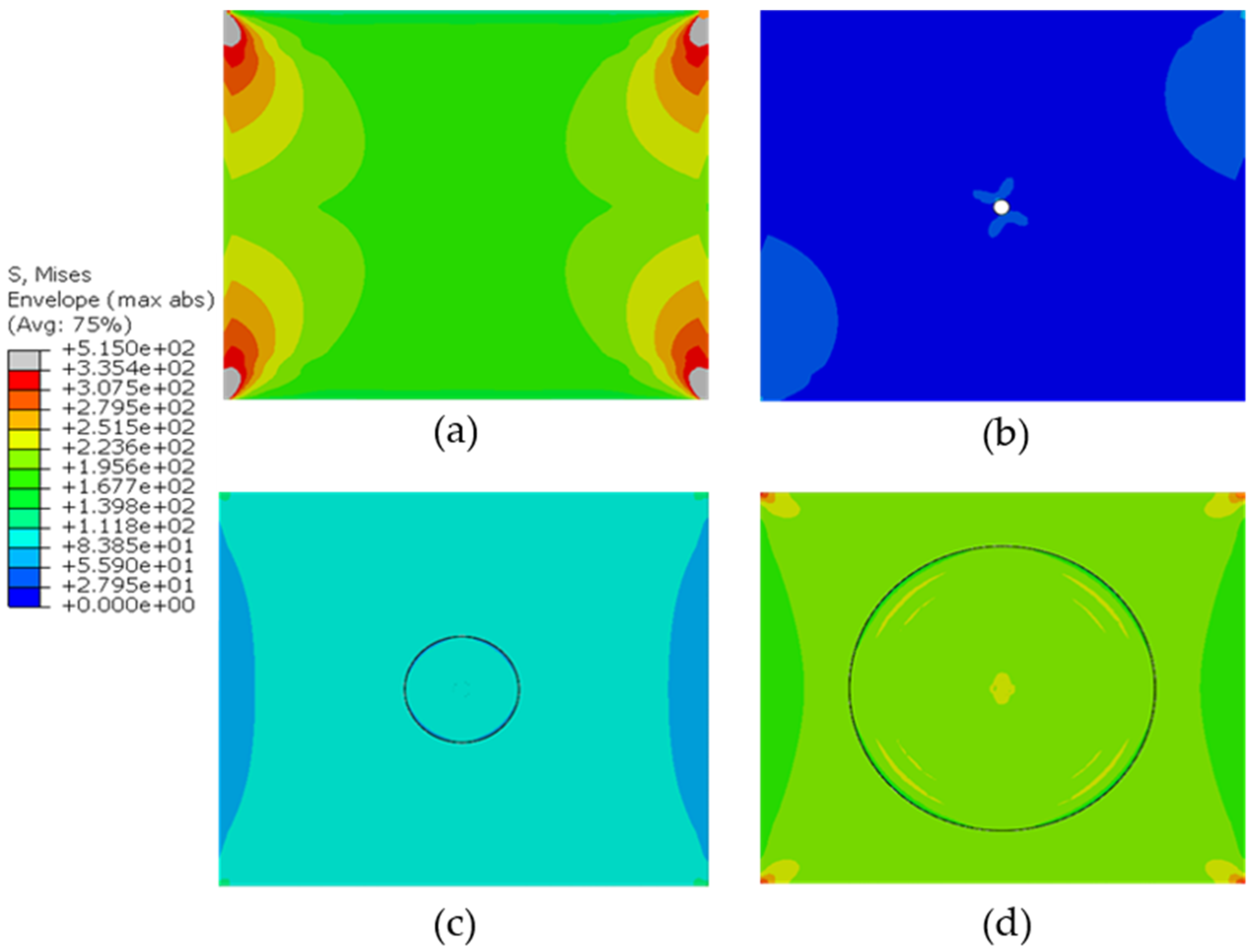
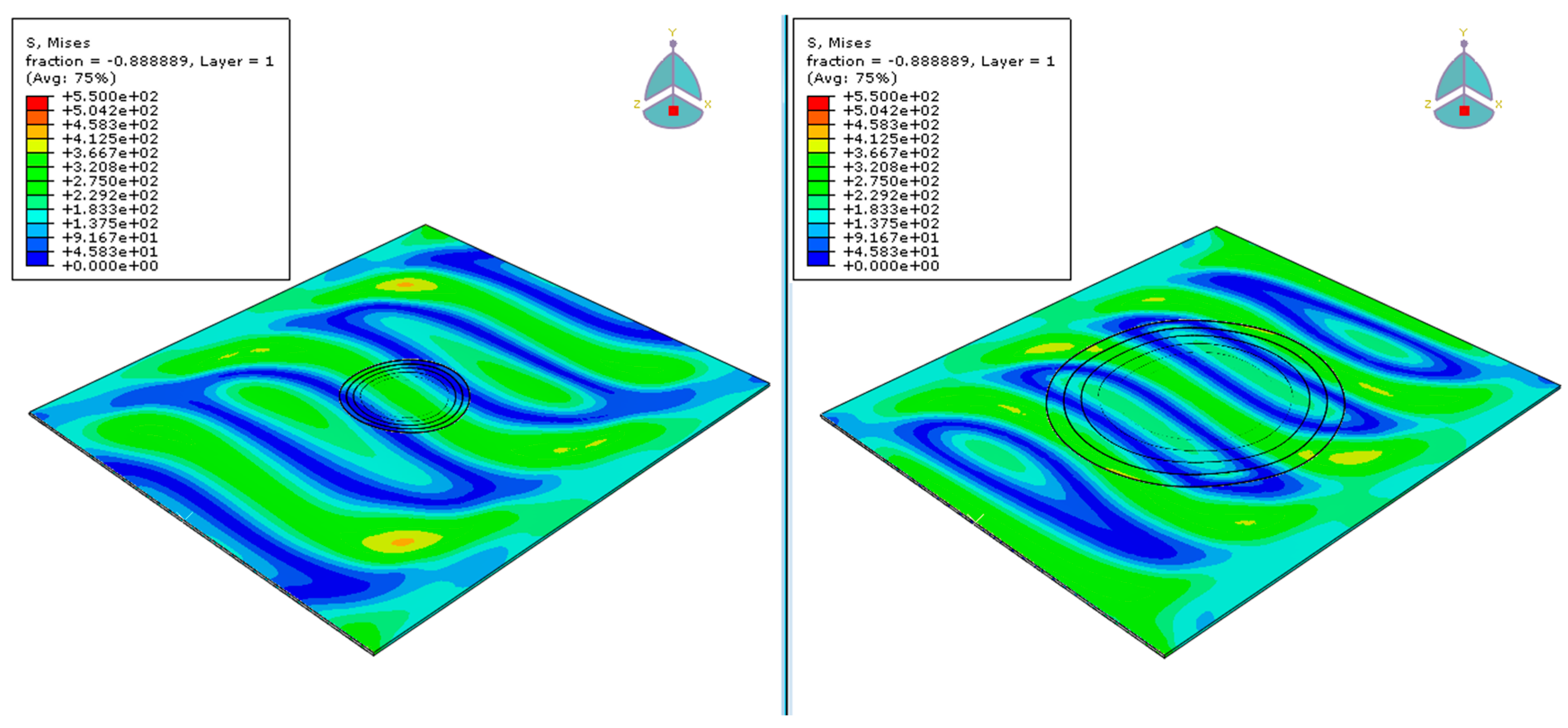
Comparative results for the undamaged and damaged plates as well as the repaired plates with scarf ratio 20 and 60, that correspond to the smallest and largest patch, respectively, follow. The results represent the response of the plates the moment just before the failure occurred (failure using the criterion Von Mises), which was detected from the force-displacement diagram and then selecting the closest frame to that moment from Abaqus’ field output.
Figure 5 shows an illustrative comparison of the distributed Von Mises stresses just before the failure for four plate cases; pristine, damaged, repaired with ratio 20 patch and repaired with ratio 50 patch. It is observed that the biggest patch can withstand higher stresses before failure, whereas the smaller patch improved the performance of the damaged laminate, but to a smaller degree. Compared to the damaged laminate, the biggest patch can increase the maximum stress capacity of the structure even six times. Regarding the smaller patch, it could achieve approximately two times higher stress capacity. Nevertheless, none of the patches managed to recover the stress capacity of the pristine laminate before failure.
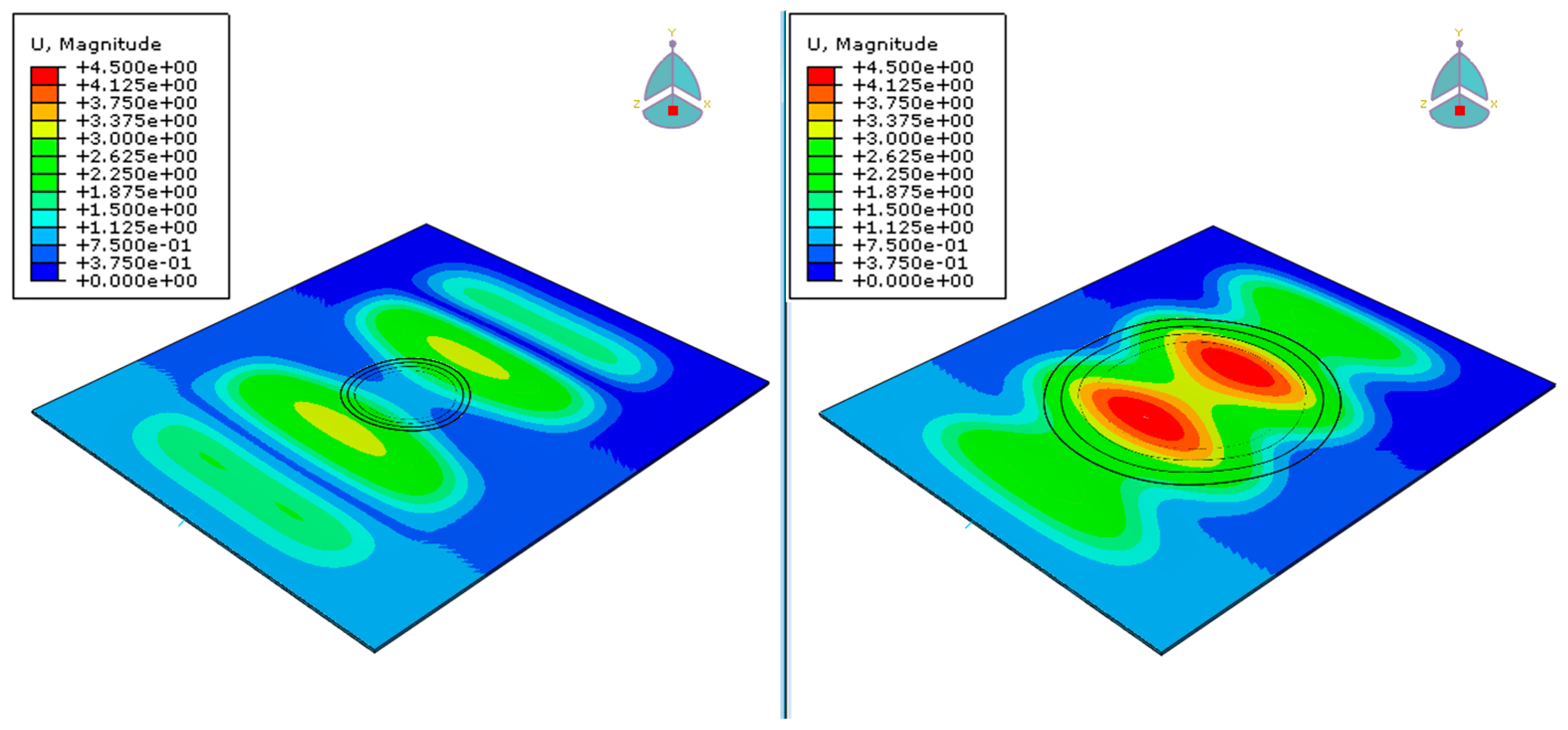
The worst and the best performed repair scenarios were picked, the 20 and the 50 scarf ratios, respectively, for a direct comparison between the weakest and the strongest patch. It has to be noticed that the patch with scarf ratio 60 was as strong as the 50 based on the comparison above, but more material has to be removed so it was excluded.
Figure 6 presents the displacement magnitude on the two plates. This value represents an equivalent of the X, Y, Z displacements for each point, in this case for each element, of the laminate. It is notable that the maximum magnitude on the left laminate is approximately 3.37 mm while on the right is 4.5 mm. This can be justified due to the fact that the latter can withstand bigger displacements before failure occurs.
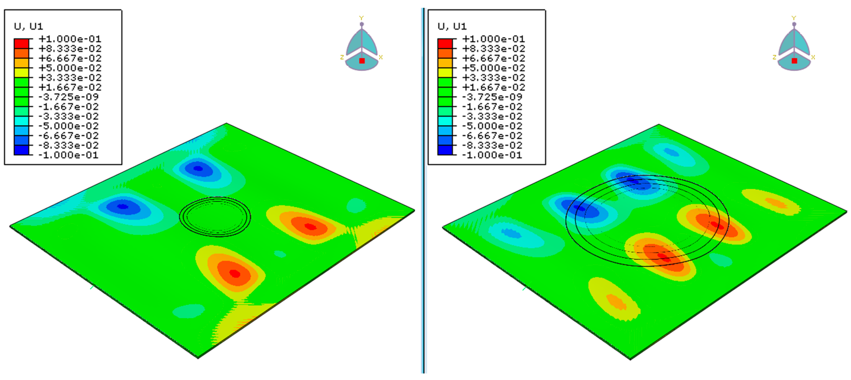
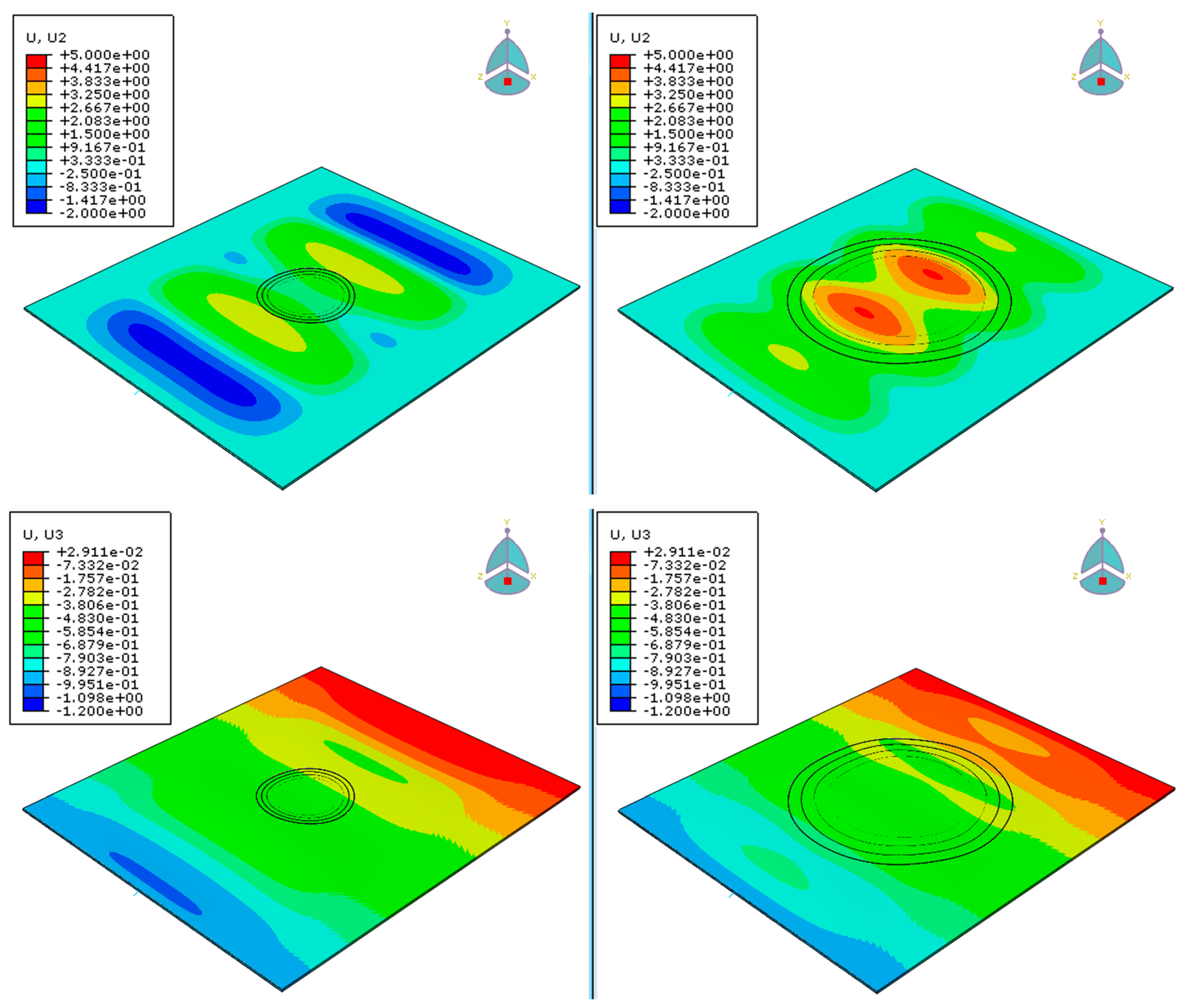
Going individually to each axis,
Figure 7 illustrates the displacements in the X, Y and Z- axis and represents the case when the applied displacement was approximately 1.2 mm i.e., just before the failure for both plates. For the patch with ratio 20 the maximum displacement in the X-axis was 0.1 mm, while the maximum displacement in the Y-axis was 3.25 mm. In regard to the displacement in the Z-axis, corresponds to the loading-axis displacements. For the patch with ratio 50 the maximum displacement in the X-axis was 0.1 mm, while in the Y-axis was 5 mm. From the above, it is evident that the two laminates were similarly deformed in the X-axis. However, in the Y-axis the laminate with the ratio 50 had 35% higher displacements, as it withstands a bigger load and had a different buckling mode before failure.
Moving to stresses, the stress distribution of the two laminates is shown below in
Figure 8. The figures were captured at the same time frame as before, just before failure, to allow a direct comparison and better understanding of the response of the repaired laminates.
Based on the Von Mises criterion, the maximum stress that occurred on the laminate with the smaller patch is 450 MPa, while on the laminate with 50 scarf ratio the maximum stress is approximately 400 MPa. The smaller patch had higher stresses than the laminate with the bigger patch, at the same time frame. That means that it will more quickly reach its ultimate strength/fracture point.
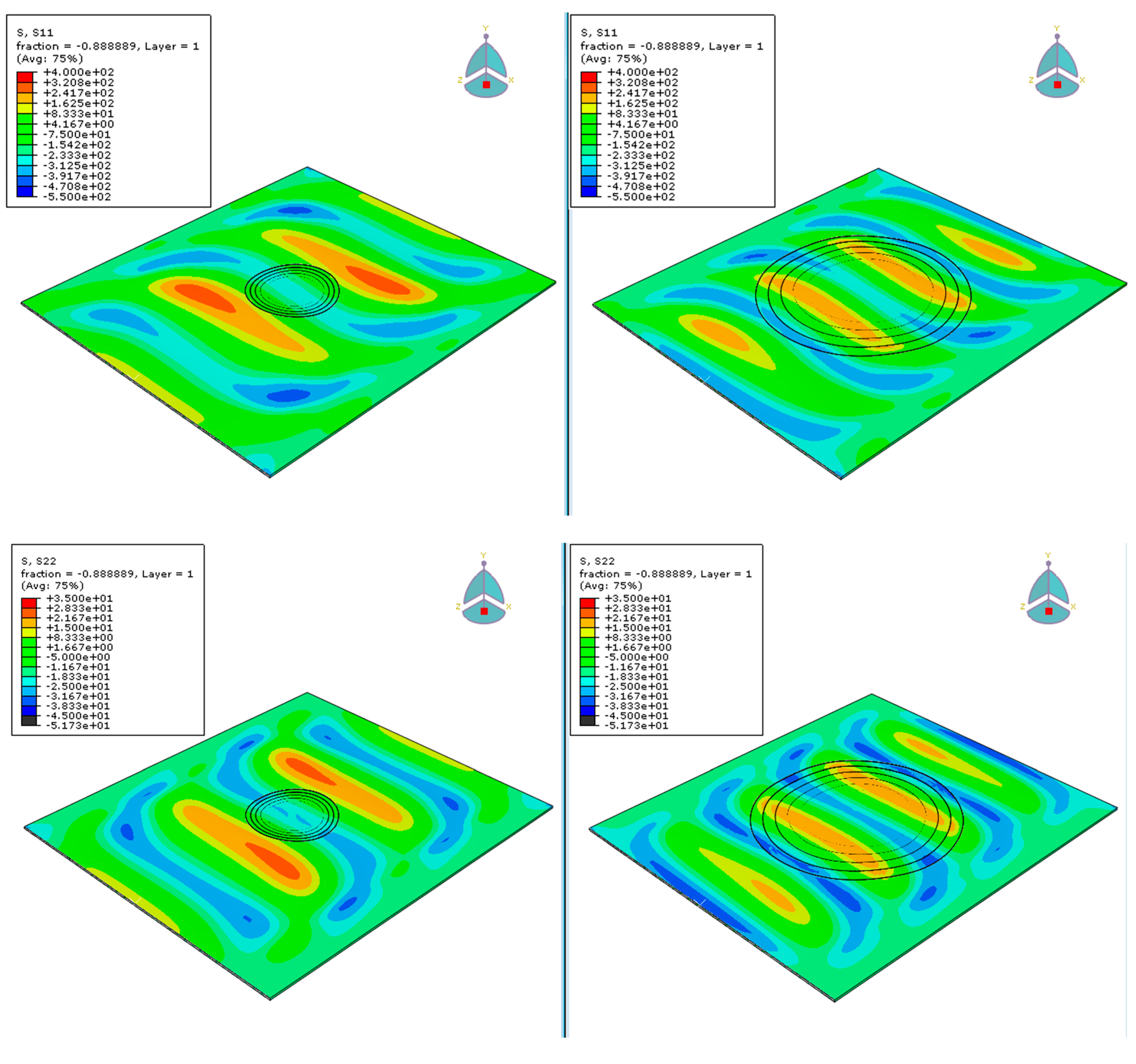
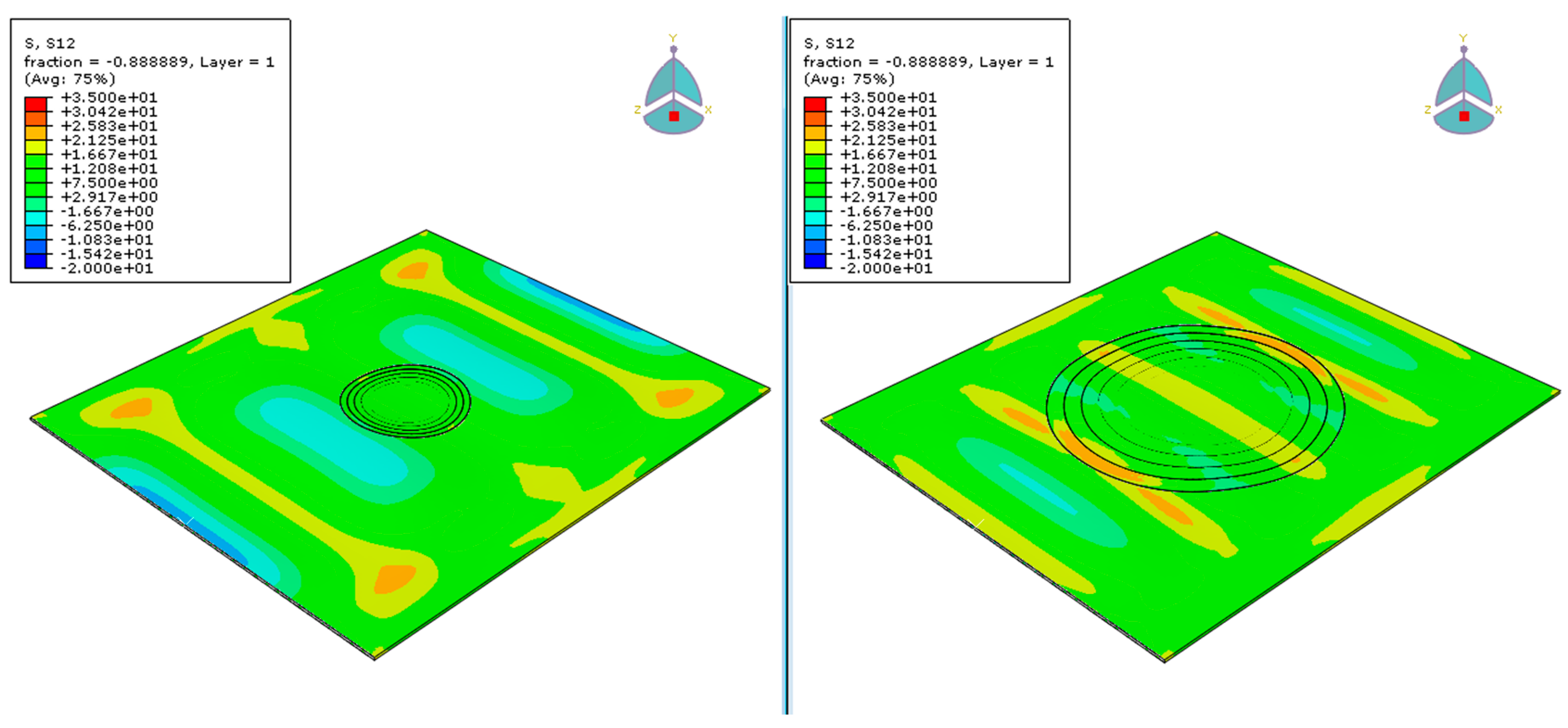
From the stress distributions in
Figure 9, it can be easily observed that the maximum compressive stress in the X-axis for both laminates is about 550 MPa. On the other hand, the maximum tensile stress on the laminate with 20 ratio is 320 MPa, while on the laminate with 50 ratio is about 240 MPa. This difference would result in an earlier matrix failure of the plate with the smaller patch, that would potentially lead to delaminations and final failure. In the Y-axis, the maximum compressive stress for both the laminates is about 40 MPa, while the maximum tensile stress for the smaller and the larger patch is 28 MPa and 21 MPa, respectively. The shear stresses in the XY plane are similarly distributed on both laminas. However, the maximum stresses occurred on the 4 edges of the lamina for the laminate with 20 ratio and at the center of the plate for the laminate with 50 scarf ratio. It can be said that as the higher stresses were reached earlier by the plate with the 20 scarf ratio, it would have the worst performance, verifying the comparison of
Figure 4.
Results showed that it is very important to repair a composite structure that has been damaged, as the repair would not only prevent damage propagation but will also restore the laminate’s stiffness up to 4 times and its maximum stress capacity up to 6 times compared to the damaged.
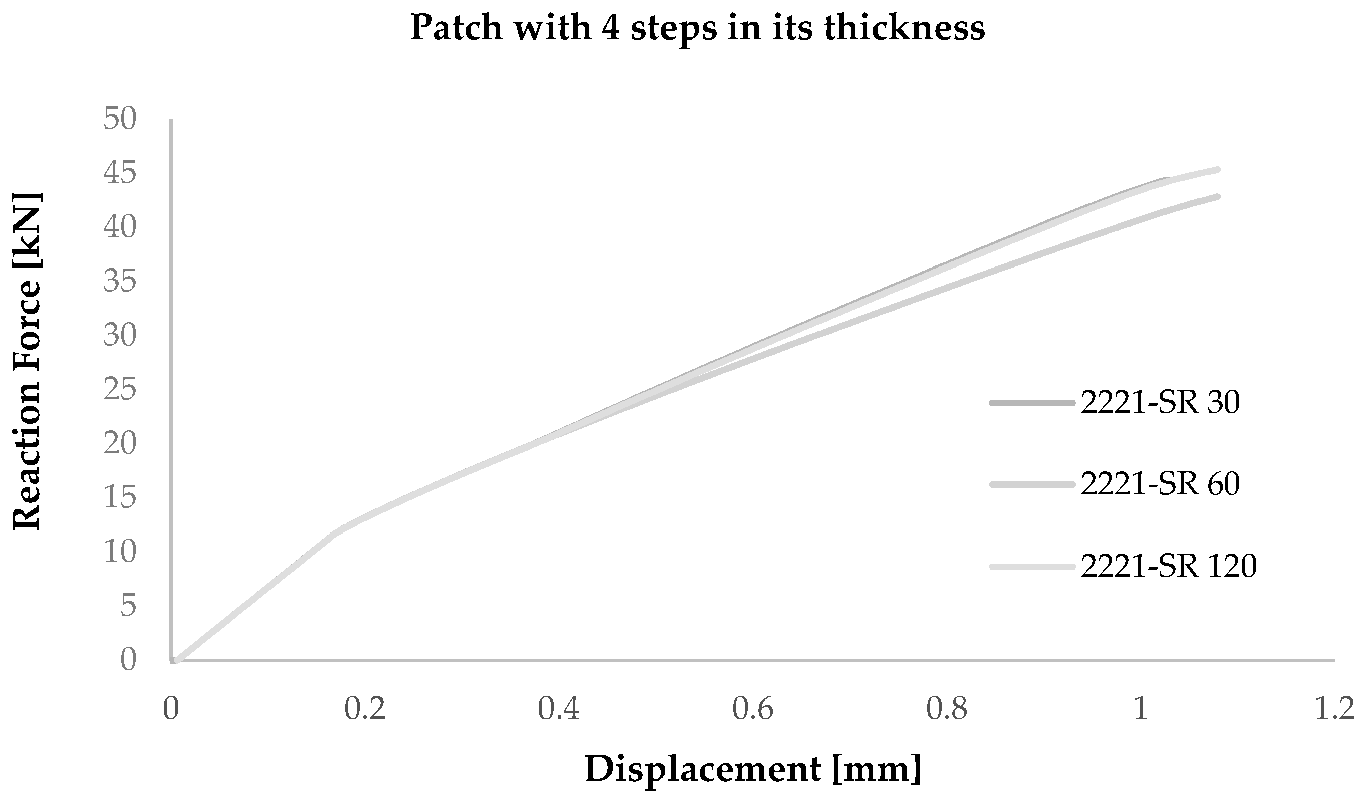
Moving to the effect of the patch steps compared to the number of the plies that constitute that base laminate,
Figure 10 and
Figure 11 present the response of the repair patch with 4 and 3 steps through its thickness, respectively. This means that instead of having a ply by ply step repair, the patch steps will go every two and three plies, respectively. The two-ply step repair will result in a four-step patch (2221), while having a three step repair will result in a three-step patch (333).
Based on
Figure 10, it is evident that the scarf ratio does not significantly affect the response of the repair patch. Moreover, the buckling load is lower compared to the damage scenario and is equal to 14 kN, which is more than 4 times lower than the corresponding load of the 9-step patch with 50 scarf ratio.
The same behavior was observed for the scenario with 3 steps in its thickness (
Figure 11) where the buckling load was equal to 12.5 kN for all scarf ratios and was slightly lower than the patch that consisted of 4 steps. A minor increase of this load can be observed in the patch with ratio 120, where it is equal to 17 kN, but is again lower than the plate with 9 steps and 50 scarf ratio.
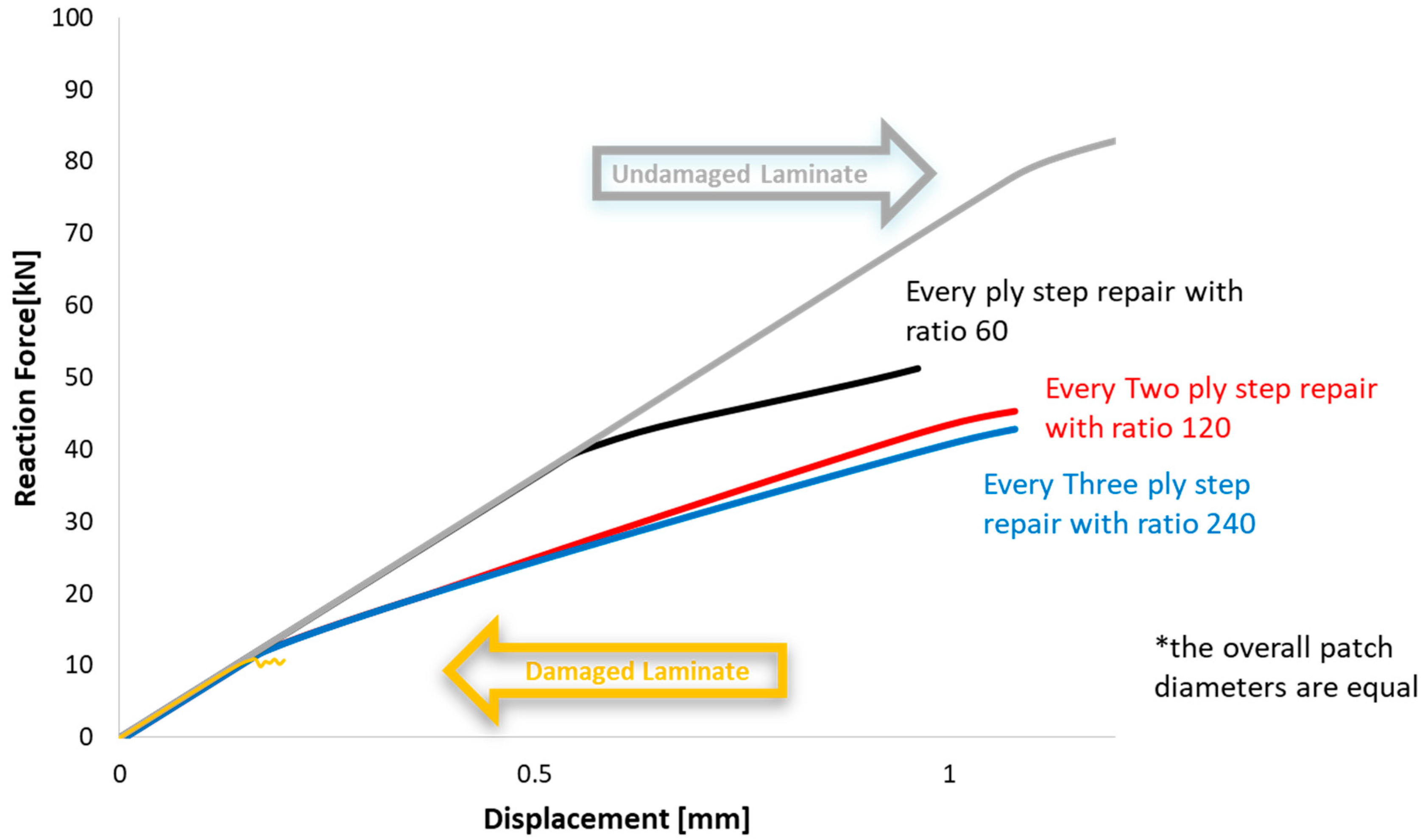
Figure 12 summarizes the maximum buckling and failure loads prior to failure for a damaged, an undamaged and three repaired plates. The overall patch diameter for the three repaired plates is equal. However, they have different number of plies in each step, varying from 1 to 3. The repair patches that have 2 and 3 plies in each step increase the maximum force that the structure can withstand but slightly increase the buckling load compared with the damaged plate. On the other hand, compared to the damaged plate, the patch that has one ply in each step increases buckling load 4 times and the failure load from 10 kN to 50 kN, and only 40% less compared to the undamaged plate. These means that the total strength of the repaired laminate is not only affected by the scarf ratio and the overall diameter of the patch, but also by the thickness of the step of the repair patch.
To summarise, if damage occurs, it is only practical to induce a repair patch that has one ply in each step. However, more experiments need to be conducted in order to verify which is the optimal scarf ratio. The outcome of the current study is that the higher the scarf ratio, the stronger the repaired structure. However, this is valid only up to a certain value of the scarf ratio. Above that value, no significant increase of the total strength can be observed. For the scenario that the repair patch has equal number of steps as the base laminate, there was a remarkable surge of the failure load while the scarf ratio was increasing from 20 to 50. The scarf ratio 50 was a threshold, above which no significant change in the strength that could be attained with the use of the repair patch could be seen.
4. Discussion
Even though many studies examined the repair methods in composite materials, the literature is limited regarding models studying the influence of steps in stepped scarfs. The purpose of this investigation was to examine how the geometry of a stepped repair patch influences the behaviour of a repaired plate under compressive loading.
It was evident that the stepped scarf repair patch significantly increased the strength of the damaged plate and recovered its strength up to 4 times. However, none of the examined patches was able to fully recover the strength of the undamaged laminate. To optimize the recovery of the damaged laminate, it is recommended to use patches with number of steps equal to the number of the repaired plies. It seems as though decreasing this number will significantly plummet the estimated failure load of the repaired structure.
Also, it is suggested that a parametric analysis prior to repairs be conducted, as a bigger patch does not necessarily mean greater strength and vice versa. Wisely choosing the geometry of the repair patch that will be used is vital, since a wrong decision could deteriorate the mechanical performance of the structure and also could lead to increased material removal that affects the overall repair procedure time and cost.
However, further study is suggested to be carried out that would allow more scarf ratios to be examined for more accurate and general outcomes.

 ,
, 


