Article

Synthesis and Characterization of Graphite Composite Foams for Oil Spill Recovery Application

by
Vincenza Brancato
1,*,
Elpida Piperopoulos
2,
Emanuela Mastronardo
3,
Luigi Calabrese
2,
Candida Milone
2 and
Edoardo Proverbio
2
1
Istituto di Tecnologie Avanzate per l’Energia “Nicola Giordano”, CNR ITAE, 98126 Messina, Italy
2
Department of Engineering, University of Messina, 98166 Messina, Italy
3
Thermochemical Processes Unit, IMDEA Energy Institute, 28935 Madrid, Spain
*
Author to whom correspondence should be addressed.
J. Compos. Sci. 2020, 4(4), 154; https://doi.org/10.3390/jcs4040154
Submission received: 10 October 2020 / Revised: 13 October 2020 / Accepted: 16 October 2020 / Published: 19 October 2020
(This article belongs to the Special Issue Graphene Composites)

Abstract

:
The aim of this paper is the synthesis and characterization of a composite silicone foam filled with expanded graphite (EG) for oil spill recovery applications. The EG foams were obtained using a foaming slurry consisting of a mixture of siloxane compounds as the matrix with an EG filler. The effect of the filler content’s performance on an innovative composite silicone-based foam was investigated. All the obtained samples exhibited an open cell morphology. Each foam was evaluated in four commonly used oils (kerosene, pump oil, naphtha and crude oil). Additionally, kinetics was studied in order to investigate the physical, chemical and mass transport mechanisms that act during the absorption phenomenon and uptake evolution of the contaminants. Foam filled with 3% of EG exhibited the highest absorption capacity, particularly with light oils kerosene and virgin naphtha (854 and 1016 wt.%, respectively). Furthermore, the kinetic study showed that pseudo-second order mechanisms better fitted the composite absorption performances, suggesting that the oil sorption into EG filled polydimethylsiloxane (PDMS) foams could be related to chemisorption mechanism. The results evidenced a good oil sorption capability and water/oil selectivity indicating this class of materials as a potentially applicable material for oil spill remediation.

1. Introduction

Currently, no European country is self-sufficient from an energy point of view, more than half of the energy consumed in Europe, in fact, comes from non-European countries [1]. Italy imports 76.9% of its energy needs [2]. The supply of crude oil takes place exclusively by sea, this involves environmental risks related to the spillage of crude oil due to accidents or during loading/unloading operations [3,4]. REMPEC, Regional Marine Pollution Emergency Response Center for the Mediterranean Sea, responsible for the Prevention and Emergency protocol of the Barcelona Convention in 1976, on the prevention and management of accidents resulting from marine pollution, found that from 1 August 1977 to 31 December 2010, 312,000 tons of oil were spilled into the Mediterranean Sea, due to 545 accidents.
The causes of marine pollution from petroleum products are essentially of two types: (i) accidents, such as fires, explosions, collisions and (ii) operational activities, such as the loading and unloading of oil tankers and refueling operations (discharge of ballast water or residues from the washing of tanks, sludge or bilge water). These latter activities, although illegal, are still a widespread practice today. The most common types of intervention are the use of floating barriers, manual and mechanical removal and in particular the use of absorbents and dispersants.
Among the oil absorbents tailored for oil spill remediation, carbon-based materials acquired a relevant interest due to the combined properties such as high pore volume, suitable oil/water selectivity, good chemical and mechanical stability [5,6,7].
In recent years, several efforts were carried out in order to optimize carbonaceous macro and microporous sponges for oil spill clean-up [8]. The purpose is to realize an interconnected porous structure with high surface area in order to enhance the pollutant absorption performances. Porous polymeric absorbents with tailored surface properties (e.g., superhydrophobicity, oleophilicity, highly interconnected porosity) showed to be an effective and suitable approach in this application context, overcoming some of the limitations of traditional absorbents, such as low absorption capacity and selectivity [9,10]. Nguyen et al. [11] investigated graphene-based sponges by using a simplified dip-coating technique. Their results evidenced the relevant superhydrophobicity–superoleophilicity exalting the oil selectivity of the material. A good chemical stability and recyclability was highlighted. A similar approach was applied by Liu et al. [12] that deposited a graphene coating, by dip-coating method, on a polyurethane (PU) sponge. The functionalized PU foam showed excellent hydrophobic–superoleophilic properties (oil absorption >80 g/g).
Very significant absorption properties have been found in innovative carbon nanotubes (CNT) based foams [7,13,14,15]. In order to simplify their production cycle and production costs, Zhao et al. [16] proposed a composite vermiculite-CNT foam with acceptable results. Analogously, the use of a silicone foam matrix could be identified as a potential suitable support as a CNT filler for composite sorbent foams with effective reuse capability [17]. Even though carbon-based sponges have been widely investigated—highlighting relevant oil absorption capabilities—until now, these materials have not solved the cost issues related to manufacturing and the oil spill recovery process lay-out that limit their industrial use. In such a context, exfoliated graphite represents a suitable alternative of conventional carbonaceous materials thanks to its low-cost, non-toxicity, and availability. Furthermore, the main feature that makes graphite potentially applicable for oil spill recovery is the high hydrophobic and oleophilic nature of this material. Gnasemi et al. [18] showed that EG can be successfully applied for oil removal from seawater thanks to its easy synthesis process, low-cost and acceptable sorption capability. Based on these peculiarities, the combination of an exfoliated graphite filler with a spongy macroporous matrix can represent a winning approach, as evidenced by Vásquez et al. [19] using a macroporous polyurethane support, and Bentini et al. [20] in a poly (vinylidene fluoride) porous matrix.
In particular, Vasquez [19] et al. investigated a promising approach to optimize the oil recovery capabilities by using a hydrophilic and underwater oleophobic material characterized by highly interconnected macroporous foams, following a solvent-free straightforward fabrication process. The composite foams were constituted by EG granules, a cost-effective carbon-based material coupled, by simple mixing, with waterborne polyurethane foam. Thanks to well interconnected pores and a highly accessible surface area of the designed composite materials, an oil rejection efficiency of 96.85% was reached. Analogously, Bentini et al. [20] proposed a new synthesis approach for a composite sorbent foam in order to reduce the scale-up issues and production cost of the composite foams for this application. They proposed a simplified synthesis method to produce a solvent free polyvinylide flouride (PVDF)-based foam. In particular, EG granules were used as sorbent fillers in a PVDF matrix, directly by simple mixing, inducing the foaming by a following heating step. The obtained product was a PVDF-EG foam with a porosity of about 90% and a very high surface area and mean oil absorption capacity of 12 g/g. To this concern, the aim of this work is to investigate a simple synthesis of a silicone-exfoliated graphite (EG) foam, with hydrophobic and oleophilic surface properties. The new synthetized material needs to be tailored in order to acquire both good sorption capacity and excellent mechanical resistance to configure its effective oil spill reusability. In fact, the use of a siloxane elastomeric matrix is directed to permit the reuse of the absorption material, thus reducing the disposal costs of the material, and significantly increasing its useful life. Although, it is worthy of note that this material choice adds an issue concerning the final disposal or recycle of the composite foam waste. As investigated elsewhere, the mechanical properties of the graphite filler (i.e., carbon nanotubes) have a positive influence on the reusability of the composite material, guaranteeing its reuse for 10 times, while maintaining its absorbent capacity [17].
To combine high absorption performances with a versatile and economical synthesis process, also enhancing the economy of the system thanks to a potential reuse of the product for several absorption cycles, represents a key point for the development of industrially applicable materials in the oil recovery field. Different EG amounts were used as the filler. Four oils (kerosene, virgin naphtha, pump oil and crude oil) were investigated to assess the sorption capability of the composite foams. As a reference, the foam’s behavior in water was also tested. The morphology of the foam was evaluated by scanning electron microscopy evidencing an open and homogenous cell structure of all investigated materials.

2. Experimental Part

2.1. Synthesis of Composite Silicone Foams

The foam synthesis occurred as reported elsewhere [17,21]. The interaction of the two siloxanes (both supplied by Gelest Inc., Morrisville, NC, USA), a hydrosiloxane (Poly (dimethylsiloxane-co-methylhydrosiloxane), trimethylsilyl terminated, PMHS, pur. 97% M.W. 5500–6500 CAS: 68037-59-2) and a silanol terminated polydimethylsiloxane (PDMS, pur. 97% M.W. 1100,000 CAS: 70131-67-8), that supplied the Si-OH groups, giving rise to the “Dehydrogenative Coupling” process which allowed, by a condensation reaction, the foaming process.
Water and ethanol were used as solvents and Tin(II) 2-ethylhexaonate (Sn(II)) d:1.12, M.W. 405.11, 50%, CAS. 301-10-0, Aldrich Chemical Co., St. Louis, MO, USA) as the catalyst. As the filler, xfoliated graphite (EG), supplied by TIMREX C-THERM 002 TIMCAL Ltd. (Bironico, Switzerland), was used. The purchased filler, as reported in its technical data sheet, presents a bulk density of 0.04 g/cm3 and a specific surface area of 25 m2/g. EG was used as received for the composite silicone foams synthesis in a percentage of 3.5, 5.5 and 7.0 wt.%. Initially, the EG was dispersed in ethanol and water by means of ultrasonic bath and magnetic stirring. Then, the mixture was added to PDMS and mixed again for about 60 s, until all the ethanol evaporated and the weight became constant. Afterwards, PMHS was added to the obtained mixture in the ratio PDMS/PHMS 2:1. Ethanol and water were used in this phase as solvents to reduce the viscosity of the slurry. Finally, the tin catalyst was added to the slurry mixing vigorously for about 15 s. The obtained slurry was put in a cylindrical mold with a diameter of 2 cm to give a proper shape to the foams. The pans, full at 2/3 of their capacity, to complete their foaming process, was put in the oven at 60 °C for 72 h, in order to assure the complete removal of the ethanol and the water. Table 1 lists all the produced foams highlighting the amount of each chemical compound (normalized in percentage). A pristine foam specimen was produced for having a reference. A number followed by the acronym EGF codified the samples. As reference, the code 0-EGF refers to the sample produced without the addition of EG, while the code 5-EGF indicates the sample made by addition of 5.5% of EGF.

2.2. Morphological Analysis

Foam morphology and surface characterization were evaluated by scanning electron microscope (FEI Quanta FEG 450, FELMI ZFE, Graz, Austria) operating at 5.00 kV. The bulk (apparent) density of the foams was computed from the weight to volume ratio.

2.3. Sorption Capacity Tests

Pump oil, crude oil, kerosene and virgin naphtha were selected as oils suitable for sorption experiments. Table 2 summarizes the density (ρ) and the dynamic viscosity (μ) of these oils.
The sorption experiments were carried out as follow: a cube (about 1 × 1 × 1 cm3), filled and unfilled, was weighed and then put into the tested oil or water at room temperature for 30 s and under slow stirring. After sorption process, the samples were held for 30 s to permit to the residual oil to drip away. Finally, the foams were weighed again to evaluate the uptake according to equation 1:
Q t = m t m 0 m 0
where Qt (%) is sorption capability, uptake, of the foam at t sorption time; mt (g) is the weight of sample after sorption and m0 (g) is the original weight of the sample. The sorption saturation is defined as the Qt (%) value at which the uptake remains constant.

3. Sorption Kinetics Models

To evaluate the sorption kinetics of the composite foam, four models were considered in order to assess the sorption rate of oils and to elucidate the interaction mechanism sorbent/sorbate.
The considered models are:
  • pseudo-first order (PFO) model
  • pseudo-second order (PSO) model
  • Elovich model
R2 (R-squared), between experimental and fitting data, was determined for each model to evaluate the goodness of the fitting.

3.1. Pseudo-First Order Kinetic Model

The PFO kinetic model, introduced by Lagergren [22], starting from the sorption capacity, defines the sorption phenomenon that occurs at the interface solid-liquid, according with the following equation:
d q t d t = K 1 ( q e q t )
where qe (mg/g) and qt (mg/g) are the sorption capacities (expressed as amount of sorbate sorbed on sorbent unit mass) at equilibrium conditions and at time t, respectively. K1 (s−1) is the rate constant of the pseudo-first order sorption reaction. Integrating Equation (1) with boundary conditions qt = 0 at t = 0 and qt = qt at t = t a linear relation can be obtained, as:
l n ( q e q t ) = l n ( q e ) K 1 t
By using Equation (2), the K1 value can be calculated as the slope of l n ( q e q t ) versus time t. The initial sorption rates h0,1 (g/g min) can be calculated from Equation (3) for qt→0, as:
h o , 1 = K 1 q e

3.2. Pseudo-Second Order Kinetic Model

The POS kinetic model, developed by Ho et al. [23], is generally applied for solid–liquid systems. It is based on the following expression:
d q t d t = K 2 ( q e q t ) 2
By integration of Equation (4) at boundary conditions (qt = 0 at t = 0 and qt = qt at t = t) the pseudo-second-order kinetics may be expressed in a linear form as:
t q t = 1 K 2 q e 2 + t q e
where K2 (g·mg−1min−1) is its rate constant. The slope and intercept of linear t/qt vs. time plot can be used to determine second order rate constant, K2, and maximum equilibrium sorption, qe, respectively.
Furthermore, the initial sorption rates h0,2 (mg·g−1 s−1) and half sorption time (s) can be calculated as:
h o , 2 = K 2 q e 2
t 1 / 2 = 1 K 2 q e
considering that from Equation (4), dqt/dt approaches k q e 2 when qt→0

3.3. Elovich Model

The Elovich model [24] is widely used for absorption kinetics and it is based on the following equation:
d q t d t = α e β q t
where qt (mg·g−1) is the sorption capacity at time t. The coefficient α (mg·g−1 s−1) can be considered the initial sorption rate considering that dqt/dt approaches α when qt → 0. β (g·mg−1) is the absorption constant during any one experiment and it is related to the extent of surface coverage and the activation energy for chemisorption [25]. Integrating, considering that qt = qt at t = t and qt = 0 at t = 0, and assuming also that α, β and t >> 1, Equation (9) is obtained.
q t = l n ( α β ) β + l n ( t ) β
Therefore, by plotting qt versus ln(t), a straight line should be obtained. According to the Elovich kinetic model the constant α and β can be calculated from the slope and intercept of the interpolating line.
Table 3 reports a brief summary of the considered kinetic models applied in this work.

4. Results and Discussion

4.1. Morphological Analysis

The 0-EGF sample (Figure 1a) exhibits an isotropic structure constituted by slight spherical cells well interconnected each other. The EG filled foams (Figure 1b–d) evidence a progressive decrease in bubble size. This behavior can be ascribed to the high viscosity and nucleating phenomena induced by EG addition in the siloxane mixture [26]. In particular, by increasing the EG amount up to 5.5 wt.%, the particle size has no relevant modification. On the contrary, the 7-EGF sample shows very small and irregular pores. In fact, by increasing the graphite content, the foam tends to become compact due to the lower foaming ratio. This gradual evolution of the morphology towards a more compact and dense foam can be attributed to the foaming process. Bubble size is influenced by the coupling reaction occurring between the siloxane compounds, which implies physical–chemical bubbling [27]. The high viscosity on the composite slurry hinders the coalescence phenomena during bubbling and furthermore reduces the bubble diameter at pressure equilibrium [28]. Therefore, local heterogeneities in bubble shape occurred, as evidenced by Figure 1d referring to the 7-EGF sample. The morphology of this batch is characterized by a bi-modal distribution with small and medium sized cells. Furthermore, the bubble’s shape is often irregular due to incomplete coalescence [29]. Due to filler addition, the foam flexibility capabilities are reduced, favoring the triggering of defects or cracks in the foam bulk.
By digital image analysis, mean bubble size and apparent density are determined for each foam (Table 4). Mean bubble size (BS) has been calculated as the equivalent average diameter of the bubble, discriminated by ImageJ software, on nine SEM micrographs for each batch. Afterwards, the bubble diameter was rectified by using the Schwartz–Saltykov (SS) method [30]. By using this approach, without a specific constrain concerning the shape and size distribution of the spheroidal particles, the three-dimensional bubble distribution can be derived by two-dimensional diameters data [31]. The apparent foam density (ρa) has been determined as the weight to volume ratio. Five replicas for each batch were applied.
Table 4 shows, as qualitatively identifiable by SEM analysis, that adding the expanded graphite in the silicone matrix, the pore size decreases ~29% (from 1.75 mm to 1.25 mm for the 0-EGF and 3-EGF samples, respectively). At the same time, ρa, increases of ~10% (from 280.3 kg/m3 to 309.4 kg/m3 for 0-EGF and 3-EGF foams, respectively). The EG increase could inhibit the interaction between the siloxane compounds, thus lowering the foaming ratio. As a consequence, significantly increasing the EG filler amount, foam bubble size significantly decreases (an average bubble size of 0.59 mm was calculated for 7-EGF). Consequently, the foam density increases (339.6 kg/m3 and 531.4 kg/m3 for 5-EGF and 7-EGF, respectively). Therefore, the smaller BS value and the higher density of the foam, indirectly clarify the reduced elasticity of these samples. It is worthy of note that all foam samples have an apparent density lower than that of oil pollutants, so they are able to float during the oil spill recovery. Comparing obtained results on EG foams with the previous achieved results on CNT filled ones [17], it can be observed that by using the same filler percentage (5.5 wt.%), the pore size of 5-EGF is higher than the latter (1.20 and 1.05 mm, respectively).

4.2. Sorption Performances

Table 5 reports the sorption capacity at saturation point of all the composite foams varying the adsorbate.
The unfilled foam (0-EGF) shows a low selectivity to oil recovery. Indeed, it presents similar low sorption capacity for water and oils (both crude and pump oil). While the highest sorption capacity is obtained with virgin naphtha. Kerosene is also highly adsorbed by the 0-EGF sample.
As observed from the results, the addition of exfoliated graphite in the silicone foam enhances the sorption capacity of the silicone foam. This result indicates that the high porous structure of composite EG foam is significantly filled with absorbed oil. No significant decrease in water absorption is detected, on the contrary a high selectivity in light oils is evidenced. In kerosene oil, 3-EGF reaches 854% of absorption, even better in virgin naphtha where 1016% is reached. Additionally, in heavy oils, a clear improvement is observable (240% and 157% for crude oil and pump oil, respectively), even by increasing the EG amount the absorption properties worsen, in particular for 7-EGF, which absorption in pump oil is lower than silicone foam (101% and 119%, for 7-EGF and 0-EGF, respectively). Oil sorption capacity increases significantly with the decrease in foam density, due to the increase in the number of open cells [32].
It is important to point out, that the sorption performance of the filled foams decreases with the density of the oil (crude oil and pump oil, 900 and 860 kg/m3, respectively), as reported in Table 5. Indeed, the sorption capacity of virgin naphtha and kerosene is higher. This result is in contrast with what was found by Gui et al. [33]. This can be explained considering the dynamic viscosity (referred as µ in Table 2) of the heavier oils. Indeed, the lower the dynamic viscosity of the oils, the higher is the sorption capacity of the composite foams. Since, the dynamic viscosity represents the fluid reluctance to the deformation, it is reasonable to think that the higher dynamic viscosity of the crude and pump oils hinders their entrance into the pores of the foams [32]. While the lower reluctance of deformation of the other oils permits their absorption into the composite foams. Nevertheless, this behavior is also related to the high affinity to oils. Indeed, the chains of silane interact with the oil, due to its oleophilic nature [34], and the structure of the foams swells during the absorption process [35].
Composite foams characterized by a high EG content (5-EGF and 7-EGF) evidence a progressive reduction in sorption performances. This behavior could be associated to the higher stiffness, induced by the graphite filler, that does not allow the volume increase of the foam during absorption, decreasing the foam’s elasticity. Even though the 5-EGF sample absorption performances were worse compared to the 3-EGF ones, it shows a better behavior in oil than the CNT filled composites foams investigated in previous studies [17,26,36]. One potential explanation is that the small pore diameter of the CNT composite partially prevents the polluting oil from filling the entire available foam volume. Among the studied foams, 3-EGF represents the right compromise between hydrophobicity and polluting oil absorption, as reported in Figure 2 comparing water and oil uptake, where foams performances are compared in the same oil. The 3-EGF foam is characterized by good hydrophobic properties and high oleophilic behavior, allowing an effective and suitable oil recovery selectivity.
All the investigated foams present the lowest absorption capacity in water, as Figure 2 shows. By increasing the EG amount, the hydrophobicity increases, reaching 94% for the 7-EGF sample. The highest values are registered in light oils, like kerosene and virgin naphtha, where more than 600% of absorption is reached for all the composite foams. Increasing the EG percentage, the absorption capacity decreases, arising in virgin naphtha the same value of unfilled foam, and slowing down absorption kinetics. For heavy oils the absorption performance worsens, in particular in pump oil, where 7-EGF presents a 100% sorption. Although the 7-EGF foam has a smaller pore size (thus favoring superficial chemisorption phenomena), the high apparent density of this foam batch (see Table 2), as a consequence of a non-optimal foaming, leads to a decay of the sorbent capabilities due to an ineffective interconnection among the foam’s channels.
It is also interesting to analyze the oil sorption capacity normalized to the water sorption capability. A high efficiency index (EI), defined as the ratio between the sorption capacity at saturation in oil to the water solution, suggests a high selectivity of the filled foams that preferably adsorb the oil pollutant rather than water. An efficiency index lower than one reveals the hydrophilic comportment of the foams, inducing a higher sorption capacity of water. On the contrary, the high hydrophobic aspect of the CNT filled foams [17,26,36] decreases the water absorption performance.
Figure 3 highlights that the efficiency index of the composite foams reaches a value above seven for the kerosene and naphtha oils, confirming the high oil selectivity for the EG foams. Values equal or lower than two are obtained for the other pollutant oils. In addition, it is evident that the hydrophobic and oleophilic behavior is highly dependent on the presence of the EGF filler in the foam. The absence of filler enhances the hydrophobic behavior reducing the selectivity towards oils.

4.3. Kinetic Modeling

The absorption rate and capacity of the different oils in the composite foams were evaluated to study the physical, chemical and mass transport mechanisms that occur during absorption process of the pollutants. The sorption process is correlated to the interaction between the solute and the active sites present on the surface of the sorbent. The nature of this interaction can be physical (physisorption), chemical (chemisorption) or a mix between these mechanisms. As exposed in the previous paragraph, in the present paper three different chemical reaction kinetic models are took in account to fit the absorption experimental data: the PFO, POS and Elovich models [37]. Table 6, Table 7, Table 8 and Table 9 report the mean parameters used for each kinetic model, as well as the correlation coefficient (R2). It is easy to observe that the correlation coefficient R2 is highest when the pseudo-second order kinetic model is applied to describe all the absorption kinetics of the oils for filled and unfilled foams. The value of qe,calc obtained from the pseudo-second order kinetic model fitting was also the closest to the obtained experimental qe value, with a discrepancy ranging in about 10%. Figure 4 reports as reference the experimental data and the pseudo-second order fitting curves for the 3-EGF sample.
The goodness of the fit indicates that the oils sorption onto the filled composite foams could depend on a chemisorption mechanism, in which the attractive energy between the polymeric surface and the contaminant oils is an intermolecular bonding, having a similar strength as chemical bonds.
On the other hand, the remaining models (pseudo-first order and Elovich models) showed a poor predictive attitude of the sorbent capacity kinetics, especially for the EG based foams. Nevertheless, theElovich model is more accurate than the pseudo-first order kinetic model.
Therefore, considering the present results, it could be reasonable to hypothesize that the chemisorption phenomena is the controlling factors on the oil sorption mechanism [38,39]. Chemisorption occurs due to Lewis acid-base, hydrogen, ionic, or covalent bonds. In this case, the presence of functional groups, derived from the EG filler, contributes to the negative charge of the silicone composite. Furthermore, the foam is composed of negatively charged elements, such as C and O at the surface [40], in an acidic environment, the hydrogen ions could contribute to protonization of the foam and oil deposition into the composite foam [40]. Furthermore, in agreement with the pseudo-second order kinetics congruity, it can be assessed that the filling rate of foams with sorbed oils proportionally depends on the square number of free active sites on the sorbent surfaces [41].
Furthermore, in order to better highlight the sorption performance improvement induced by the EG filler, a comparison of sorption performances, in different oils, of silicone composite foams with varying carbonaceous fillers (EG, CNT [17] and Char [42]) is reported in Figure 5. The radar plot evidences that this class of silicone based composite foam is suitable for low density oils such as virgin naphtha and kerosene. At the same time, all of them exhibited a relevant pollutant selectivity, identifiable by the low water sorption capabilities. The addition of an EG filler, compared to other types of carbonaceous fillers, indicates the creation of greater absorbing efficiency. This behavior is attributable to the synergistic action of the effective oleophilic/hydrophobicity, chemical affinity with the matrix and the good dispersion of the filler in the macroporous matrix. According to the promising and potentially effective results, further studies will be aimed at better explaining the mechanisms of surface interaction between the EG composite foam and the pollutants. At the same time, the reusability of the composite material will be specifically investigated by evaluating the efficiency of the EG foam as a function of sorption/squeezing cycles. This is an important aspect to enhance its possible industrial applicability. High cycling capability implies greater oil sorption efficiency and effectiveness of the material, amplifying the positive impact in economic, performance and environmental terms, thus preparing it for possible use in a real application context.

5. Conclusions

The present work presents the absorption properties of silicone foams filled with expanded graphite (EG) in oil recovery. EG foams represent a practical solution for the removal of pollutants from aquifer environments. The EG content (3.5–7 wt.%) influence on the composite sorption performances was investigated. Furthermore, three kinetics models (pseudo-first order, pseudo-second order and Elovich methods), applied in oil retention applications, were evaluated to determine the sorption rate of oils onto the composite foams. Important outcomes were achieved.
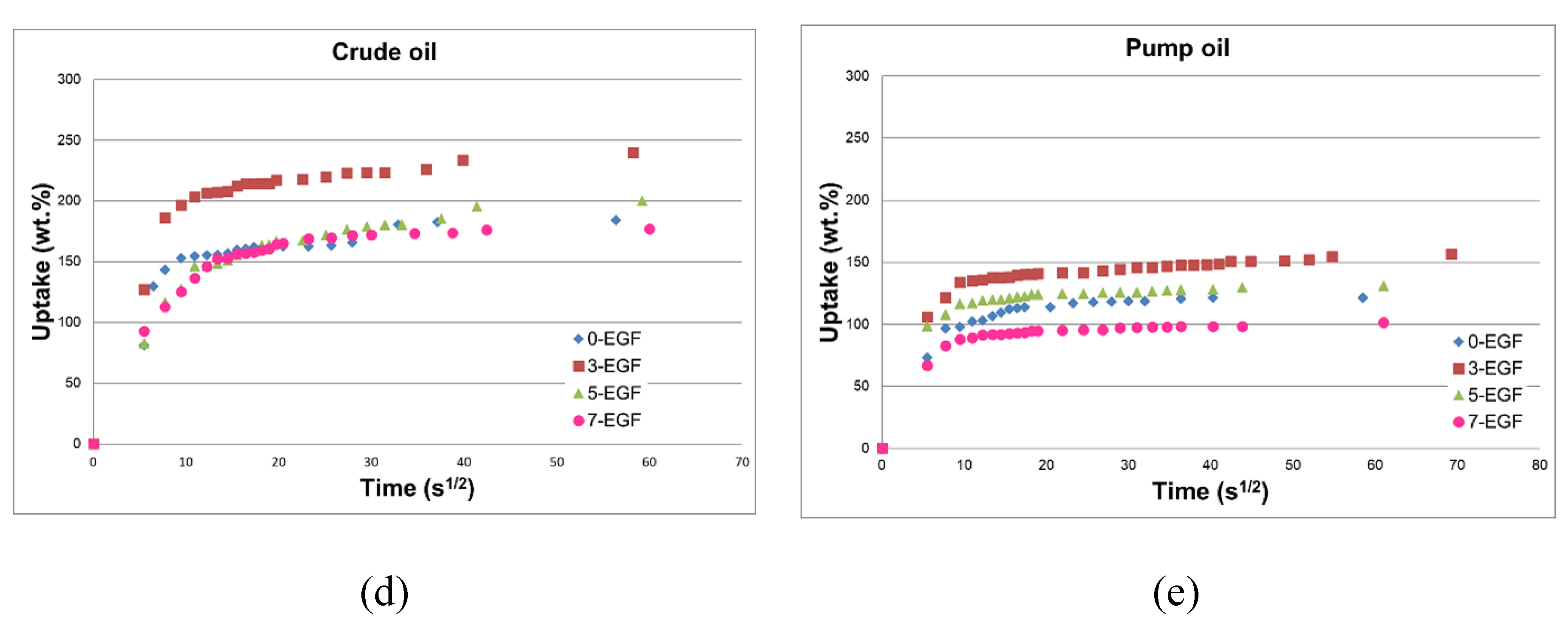
  • By increasing the EG amount, the foams’ absorption capacity was reduced.
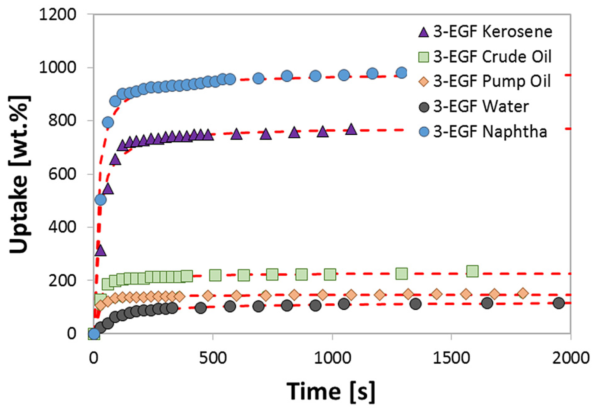
  • The 3-EGF foam exhibited the highest sorption uptake, in particular in light oils (854 and 1016 wt.% in kerosene and virgin naphtha, respectively). This result is attributed to its larger pore size (1.25 mm vs. 0.59 mm for 3-EGF and 7-EGF, respectively), and consequently its lower density.
  • The small pore diameter of 7-EGF did not allow the polluting oil to fill the entire available foam volume.
  • In heavy oils the recovery performance was maintained below 250 wt.% (240 and 157 wt.% in crude oil and pump oil, respectively). In fact, the high viscosity of the heavy oils hindered the oil entry into the pores.
  • Moreover, the silicone composite hydrophobicity (114 wt.%) allowed for sufficient oil selectivity and oil/water efficiency reaching values above seven for kerosene and virgin naphtha.
Furthermore, analyzing the results of the kinetics study, a high applicability of the pseudo-second order kinetic model (R2 ≈ 1) can be observed to describe all the kinetics of oil uptake rates of filled and unfilled foams. The good overlap of the pseudo-second order model with the 3-EGF experimental data indicates that the oil sorption into PDMS-EG composite sorbent could be related to the chemisorption mechanism, where the attractive force between the foam surface and the pollutant is an intermolecular bonding force, having a similar strength as chemical bonds.
The conducted study is preliminary to subsequent analysis on the reusability of such foams, which turned out to be promising for oil recovery application.

Author Contributions

Conceptualization, E.P. (Elpida Piperopoulos) and L.C.; methodology, E.P. (Elpida Piperopoulos); validation, V.B., and L.C.; formal analysis, L.C. and E.M.; investigation, E.P. (Elpida Piperopoulos); data curation, E.M. and V.B.; writing—original draft preparation, E.P. (Elpida Piperopoulos); writing—review and editing, E.P. (Edoardo Proverbio), V.B. and C.M.; supervision, E.P. (Edoardo Proverbio) and C.M. All authors have read and agreed to the published version of the manuscript.

Funding

This research received no external funding.

Conflicts of Interest

The authors declare no conflict of interest.

References

  1. Eurostat. Energy Production and Imports. 2020. Available online: https://ec.europa.eu/eurostat/statistics-explained/index.php/Energy_production_and_imports (accessed on 17 October 2020).
  2. Italian Government. Quadro Strategico Nazionale Sezione C: Fornitura Di Gas Naturale Per Il Trasporto E Per Altri Usi. 2020. Available online: file:///C:/Users/MDPI/AppData/Local/Temp/ALLEGATO%20III%20-%20SEZ%20C1%20-1.pdf (accessed on 17 October 2020).
  3. Nel Mar Mediterraneo record di inquinamento da idrocarburi. Available online: https://www.adnkronos.com/sostenibilita/risorse/2014/07/23/nel-mar-mediterraneo-record-inquinamento-idrocarburi_0J3mSPyBIgkZ7MEqjRg5oJ.html?refresh_ce (accessed on 17 October 2020).
  4. European Commission. I Porti Marittimi Europei Nel 2030: Le Sfide Che Ci Attendono Importanza Dei Porti. 2013. Available online: https://ec.europa.eu/commission/presscorner/detail/it/MEMO_13_448 (accessed on 17 October 2020).
  5. Kabiri, S.; Tran, D.N.H.; Altalhi, T.; Losic, D. Outstanding adsorption performance of graphene-carbon nanotube aerogels for continuous oil removal. Carbon 2014, 80, 523–533. [Google Scholar] [CrossRef]
  6. Parmar, K.R.; Dora, D.T.K.; Pant, K.K.; Roy, S. An ultra-light flexible aerogel-based on methane derived CNTs as a reinforcing agent in silica-CMC matrix for efficient oil adsorption. J. Hazard. Mater. 2019, 375, 206–215. [Google Scholar] [CrossRef] [PubMed]
  7. Zhu, K.; Shang, Y.Y.; Sun, P.Z.; Li, Z.; Li, X.M.; Wei, J.Q.; Wang, K.L.; Wu, D.H.; Cao, A.Y.; Zhu, H.W. Oil spill cleanup from sea water by carbon nanotube sponges. Front. Mater. Sci. 2013, 7, 170–176. [Google Scholar] [CrossRef]
  8. Piperopoulos, E.; Calabrese, L.; Mastronardo, E.; Milone, C.; Proverbio, E. Carbon-based sponges for oil spill recovery. In Carbon Nanomaterials for Agri-Food and Environmental Applications; Elsevier: Amsterdam, The Netherlands, 2020; pp. 155–175. [Google Scholar]
  9. Adebajo, M.O.; Frost, R.L.; Kloprogge, J.T.; Carmody, O.; Kokot, S. Porous materials for oil spill cleanup: A review of synthesis and absorbing properties. J. Porous Mater. 2003, 10, 159–170. [Google Scholar] [CrossRef] [Green Version]
  10. Pinto, J.; Athanassiou, A.; Fragouli, D. Effect of the porous structure of polymer foams on the remediation of oil spills. J. Phys. D Appl. Phys. 2016, 49, 145601–145608. [Google Scholar] [CrossRef] [Green Version]
  11. Nguyen, D.D.; Tai, N.-H.; Lee, S.-B.; Kuo, W.-S. Superhydrophobic and superoleophilic properties of graphene-based sponges fabricated using a facile dip coating method. Energy Environ. Sci. 2012, 5, 7908. [Google Scholar] [CrossRef]
  12. Liu, Y.; Ma, J.; Wu, T.; Wang, X.; Huang, G.; Liu, Y.; Qiu, H.; Li, Y.; Wang, W.; Gao, J. Cost-effective reduced graphene oxide-coated polyurethane sponge as a highly efficient and reusable oil-absorbent. ACS Appl. Mater. Interfaces 2013, 5, 10018–10026. [Google Scholar] [CrossRef] [PubMed]
  13. Gui, X.; Li, H.; Wang, K.; Wei, J.; Jia, Y.; Li, Z.; Fan, L.; Cao, A.; Zhu, H.; Wu, D. Recyclable carbon nanotube sponges for oil absorption. Acta Mater. 2011, 59, 4798–4804. [Google Scholar] [CrossRef]
  14. Gui, X.; Zeng, Z.; Lin, Z.; Gan, Q.; Xiang, R.; Zhu, Y.; Cao, A.; Tang, Z. Magnetic and highly recyclable macroporous carbon nanotubes for spilled oil sorption and separation. ACS Appl. Mater. Interfaces 2013, 5, 5845–5850. [Google Scholar] [CrossRef] [PubMed]
  15. Camilli, L.; Pisani, C.; Gautron, E.; Scarselli, M.; Castrucci, P.; D’Orazio, F.; Passacantando, M.; Moscone, D.; De Crescenzi, M. A three-dimensional carbon nanotube network for water treatment. Nanotechnology 2014, 25. [Google Scholar] [CrossRef]
  16. Zhao, M.Q.; Huang, J.Q.; Zhang, Q.; Luo, W.L.; Wei, F. Improvement of oil adsorption performance by a sponge-like natural vermiculite-carbon nanotube hybrid. Appl. Clay Sci. 2011, 53, 1–7. [Google Scholar] [CrossRef]
  17. Piperopoulos, E.; Calabrese, L.; Mastronardo, E.; Proverbio, E.; Milone, C. Synthesis of reusable silicone foam containing carbon nanotubes for oil spill remediation. J. Appl. Polym. Sci. 2018, 135, 46067. [Google Scholar] [CrossRef]
  18. Ghasemi, O.; Mehrdadi, N.; Baghdadi, M.; Aminzadeh, B. An investigation on absorption properties of exfoliated graphite for oil spill from Caspian Sea water. Eurasian Chem. Commun. 2019, 1, 318–333. [Google Scholar] [CrossRef]
  19. Vasquez, L.; Campagnolo, L.; Athanassiou, A.; Fragouli, D. Expanded graphite-polyurethane foams for water–oil filtration. ACS Appl. Mater. Interfaces 2019, 11, 30207–30217. [Google Scholar] [CrossRef]
  20. Bentini, R.; Pola, A.; Rizzi, L.G.; Athanassiou, A.; Fragouli, D. A highly porous solvent free PVDF/expanded graphite foam for oil/water separation. Chem. Eng. J. 2019, 372, 1174–1182. [Google Scholar] [CrossRef]
  21. Calabrese, L.; Bonaccorsi, L.; Freni, A.; Proverbio, E. Synthesis of SAPO-34 zeolite filled macrocellular foams for adsorption heat pump applications: A preliminary study. Appl. Therm. Eng. 2017. [Google Scholar] [CrossRef]
  22. Lagergren, S. Zur theorie der sogenannten adsorption gelöster stoffe. K. Sven. Vetensk. Handl. 1898, 24, 1–39. [Google Scholar]
  23. Ho, Y.S.; McKay, G. Sorption of dye from aqueous solution by peat. Chem. Eng. J. 1998, 70, 115–124. [Google Scholar] [CrossRef]
  24. Elovich, S.Y.; Larionov, O.G. Theory of adsorption from nonelectrolyte solutions on solid adsorbents - 2. Experimental verification of the equation for the adsorption isotherm from solutions. Bull. Acad. Sci. USSR Div. Chem. Sci. 1962, 11, 198–203. [Google Scholar] [CrossRef]
  25. Yaneva, Z.; Koumanova, B.; Georgieva, N. Study of the mechanism of nitrophenols sorption on expanded perlite ‒ equilibrium and kinetics modelling. Maced. J. Chem. Chem. Eng. 2012, 31, 101–114. [Google Scholar] [CrossRef]
  26. Piperopoulos, E.; Calabrese, L.; Mastronardo, E.; Abdul Rahim, S.H.; Proverbio, E.; Milone, C. Assessment of sorption kinetics of carbon nanotube-based composite foams for oil recovery application. J. Appl. Polym. Sci. 2019, 136. [Google Scholar] [CrossRef]
  27. Verdejo, R.; Barroso-Bujans, F.; Rodriguez-Perez, M.A.; Antonio de Saja, J.; Arroyo, M.; Lopez-Manchado, M.A. Carbon nanotubes provide self-extinguishing grade to silicone-based foams. J. Mater. Chem. 2008, 18, 3933–3939. [Google Scholar] [CrossRef]
  28. Calabrese, L.; Bonaccorsi, L.; Bruzzaniti, P.; Freni, A.; Proverbio, E. Morphological and functional aspects of zeolite filled siloxane composite foams. J. Appl. Polym. Sci. 2018, 135, 45683. [Google Scholar] [CrossRef]
  29. Calabrese, L.; Brancato, V.; Palomba, V.; Frazzica, A.; Cabeza, L.F. Assessment of the hydration/dehydration behaviour of MgSO4∙7H2O filled cellular foams for sorption storage applications through morphological and thermo-gravimetric analyses. Sustain. Mater. Technol. 2018, 17. [Google Scholar] [CrossRef]
  30. Gulbin, Y. On estimation and hypothesis testing of the grain size distribution by the Saltykov method. Image Anal. Stereol. 2008, 27, 163–174. [Google Scholar] [CrossRef]
  31. Underwood, E.E. Stereology, or the quantitative evaluation of microstructures. J. Microsc. 1969, 89, 161–180. [Google Scholar] [CrossRef]
  32. Duong, H.T.T.; Burford, R.P. Effect of foam density, oil viscosity, and temperature on oil sorption behavior of polyurethane. J. Appl. Polym. Sci. 2006, 99, 360–367. [Google Scholar] [CrossRef]
  33. Gui, X.; Wei, J.; Wang, K.; Cao, A.; Zhu, H.; Jia, Y.; Shu, Q.; Wu, D. Carbon nanotube sponges. Adv. Mater. 2010, 22, 617–621. [Google Scholar] [CrossRef]
  34. Yongmei, Z. Bio-Inspired Wettability Surfaces: Developments in Micro- and Nanostructures; Pan Stanford Publishing: Singapore, 2015; ISBN 9789814463607. [Google Scholar]
  35. Zhao, X.; Li, L.; Li, B.; Zhang, J.; Wang, A. Durable superhydrophobic/superoleophilic PDMS sponges and their applications in selective oil absorption and in plugging oil leakages. J. Mater. Chem. A 2014, 2, 18281–18287. [Google Scholar] [CrossRef]
  36. Piperopoulos, E.; Calabrese, L.; Khaskhoussi, A.; Proverbio, E.; Milone, C. Thermo-physical characterization of carbon nanotube composite foam for oil recovery applications. Nanomaterials 2020, 10, 86. [Google Scholar] [CrossRef] [Green Version]
  37. Sidik, S.M.; Jalil, A.A.; Triwahyono, S.; Adam, S.H.; Satar, M.A.H.; Hameed, B.H. Modified oil palm leaves adsorbent with enhanced hydrophobicity for crude oil removal. Chem. Eng. J. 2012, 203, 9–18. [Google Scholar] [CrossRef]
  38. Sokker, H.H.; El-Sawy, N.M.; Hassan, M.A.; El-Anadouli, B.E. Adsorption of crude oil from aqueous solution by hydrogel of chitosan based polyacrylamide prepared by radiation induced graft polymerization. J. Hazard. Mater. 2011, 190, 359–365. [Google Scholar] [CrossRef] [PubMed]
  39. Younis, S.A.; Moustafa, Y.M. Synthesis of urea-modified MnFe2O4 for aromatic micro-pollutants adsorption from wastewater: Mechanism and modeling. Clean Technol. Environ. Policy 2017, 19, 527–540. [Google Scholar] [CrossRef]
  40. Cherukupally, P.; Hinestroza, J.H.; Farnood, R.; Bilton, A.M.; Park, C.B. Adsorption mechanisms of emulsified crude oil droplets onto hydrophilic open-cell polymer foams. In Proceedings of the 32nd International Conference of the Polymer Processing Society, Lyon, France, 25–29 July 2016; Volume 1914, p. 170003. [Google Scholar] [CrossRef] [Green Version]
  41. Cheu, S.C.; Kong, H.; Song, S.T.; Johari, K.; Saman, N.; Che Yunus, M.A.; Mat, H. Separation of dissolved oil from aqueous solution by sorption onto acetylated lignocellulosic biomass—equilibrium, kinetics and mechanism studies. J. Environ. Chem. Eng. 2016, 4, 864–881. [Google Scholar] [CrossRef]
  42. Piperopoulos, E.; Calabrese, L.; Mastronardo, E.; Proverbio, E.; Milone, C. Sustainable reuse of char waste for oil spill recovery foams. Water Air Soil Pollut. 2020, 231, 293. [Google Scholar] [CrossRef]
Figure 1. Representative SEM images of 0-EGF (a), 3-EGF (b), 5-EGF (c), 7-EGF (d).
Jcs 04 00154 g001
Figure 2. Foam absorption capacities for the investigated oils: (a) water, (b) kerosene, (c) virgin naphtha, (d) crude oil and (e) pump oil.
Jcs 04 00154 g002aJcs 04 00154 g002b
Figure 3. Selectivity oil/water of all composite silicone foams.
Jcs 04 00154 g003
Figure 4. Pseudo-second order kinetics (dotted lines) of oil sorption into 3-EGF foam.
Jcs 04 00154 g004
Figure 5. Comparison of sorption performances, in different oil, of silicone composite foams at varying carbonaceous filler (EG, CNT [17] and Char [42]).
Jcs 04 00154 g005
Table 1. Composite graphite-based foams formulations.
CodeSiloxaneSolventCatalystFiller
PDMS
(wt.%)
PMHS
(wt.%)
Ethanol
(wt.%)
Water
(wt.%)
Sn(II)-EH
(wt.%)
EG
(wt.%)
0-EGF47.623.84.811.911.90
3-EGF45.022.54.511.211.23.5
5-EGF45.022.54.511.211.25.5
7-EGF45.022.54.511.211.27.0
Table 2. Density (ρ) and the dynamic viscosity (μ) of selected oils.
-Pump OilCrude OilKeroseneVirgin NaphthaWater
ρ(kg/m3)8588907806301000
µ(Pa · s)0.12310.27100.00190.00120.0010
Table 3. Summary of formulas and parameters of the sorption kinetic models.
-Sorption RateSorption CapacityConstants
Pseudo-first Order d q t d t = K 1 ( q e q t ) l n ( q e q t ) = l n ( q e ) K 1 t K1 (s−1)
Pseudo-second Order d q t d t = K 2 ( q e q t ) 2 t q t = 1 K 2 q e 2 + t q e K2 (g·mg−1·s−1)
Elovich d q t d t = α e β q t q t = l n ( α β ) β + l n ( t ) β α (mg·g−1·s−1)
β (mg·g−1)
Table 4. Mean pore size (PS) and apparent density (ρa) of the studied foams.
SamplePS (mm)ρa (kg/m3)
0-EGF1.75280.3
3-EGF1.25309.4
5-EGF1.20339.6
7-EGF0.59531.4
Table 5. Sorption performances in different liquids of all composite silicone foams.
Adsorption Liquid0-EGF
(wt.%)
3-EGF
(wt.%)
5-EGF
(wt.%)
7-EGF
(wt.%)
Water115 ± 3114 ± 298 ± 3.094 ± 5.0
Kerosene544 ± 4854 ± 4796 ± 5700 ± 12.5
Virgin Naphtha726 ± 41016 ± 5911 ± 4772 ± 13.2
Crude Oil155 ± 3240 ± 2200 ± 2177 ± 9.0
Pump Oil119 ± 3157 ± 3131 ± 2101 ± 4.3
Table 6. The kinetic coefficients of pseudo-first order (PFO), pseudo-second order (PSO) and Elovich models for 0-EGF foam.
Adsorption LiquidPseudo-First OrderPseudo-Second OrderElovich
Waterqe1073.99qe1160.66Omega0.00278
K10.0060K29.974 × 10−6alpha18.538
h0,16.465h0,213.437Re0.336
R20.939R20.998R20.969
Keroseneqe7804.433qe5428.224Omega0.00085
K10.0189K28.149 × 10−6alpha354.882
h0,1147.390h0,2240.123Re0.217
R20.705R20.999R20.9511
Virgin Naphthaqe6983.01qe7327.496Omega0.000488
K10.01470K22.242 × 10−5alpha308.691
h0,1102.649h0,21204.247Re0.267
R20.824R20.998R20.9294
Crude oilqe4058.10872qe1606.2186Omega0.002630
K10.0340K20.00033alpha197.043
h0,1138.343h0,2849.520Re0.206
R20.728R20.999R20.759
Pump Oilqe773.096qe1199.678Omega0.00590
K10.0125K25.071 × 10−5alpha613.967
h0,19.654h0,272.985Re0.143
R20.745R20.999R20.769
Table 7. The kinetic coefficients of PFO, PSO and Elovich models for 3-EGF foam.
Adsorption LiquidPseudo-First OrderPseudo-Second OrderElovich
Waterqe84.56qe120.25Omega0.0343
K10.0040K28.735 × 10−5alpha2.4657
h0,10.3395h0,21.2633Re0.3026
R20.821R20.999R20.934
Keroseneqe580.04qe748.31Omega0.0058
K10.0090K20.00028alpha63.479
h0,15.2477h0,2157.282Re0.201
R20.886R20.999R20.820
Virgin Naphthaqe276.66qe1013.41Omega0.0086
K10.0060K22.841 × 10−5alpha1707.177
h0,11.6771h0,229.181Re0.1187
R20.359R20.999R20.4683
Crude oilqe145.99qe238.87Omega0.0173
K10.0116K20.000106alpha19.413
h0,11.700h0,26.0310Re0.2693
R20.764R20.998R20.7896
Pump Oilqe42.05qe154.35Omega0.2174
K10.0044K20.000157alpha3.10 × 1011
h0,10.1855h0,23.7482Re0.0320
R20.361R20.999R20.229
Table 8. The kinetic coefficients of PFO, PSO and and Elovich models for 5-EGF foam.
Adsorption LiquidPseudo-First OrderPseudo-Second OrderElovich
Waterqe98.857qe102.24Omega0.0384
K10.007K20.00053alpha3.3306
h0,10.653h0,25.523Re0.2605
R20.954R20.996R20.968
Keroseneqe562.537qe772.5942Omega0.0063
K10.006K26.543 × 10−5alpha46.461
h0,13.633h0,239.0581Re0.210
R20.960R20.999R20.990
Virgin Naphthaqe540.575qe897.0989Omega0.0058
K10.0093K20.000135alpha98.1594
h0,15.0479h0,2108.7349Re0.1951
R20.874R20.999R20.916
Crude oilqe129.403qe200.420Omega0.0306
K10.0048K26.410 × 10−5alpha17.525
h0,10.627h0,22.575Re0.183
R20.782R20.997R20.917
Pump Oilqe47.843qe126.1734Omega0.0941
K10.008K20.0015alpha4863.059
h0,10.3832h0,224.5413Re0.0834
R20.818R20.999R20.949
Table 9. The kinetic coefficients of the PFO, PSO and Elovich models for 7-EGF foam.
Adsorption LiquidPseudo-First OrderPseudo-Second OrderElovich
Waterqe81.926qe96.9305Omega0.0533
K10.0035K26.504 × 10−5alpha1.567
h0,10.2845h0,20.6111Re0.2554
R20.899R20.995R20.934
Keroseneqe657.46qe701.9896Omega0.0053
K10.0120K25.584 × 10−5alpha25.206
h0,17.9172h0,227.5199Re0.2720
R20.957R20.999R20.9638
Virgin Naphthaqe258.6308qe749.1983Omega0.017805
K10.0071K20.00012alpha81789.43
h0,11.8506h0,271.8545Re0.0761
R20.6692R20.999R20.7495
Crude oilqe75.0781qe173.5510Omega0.0508
K10.0083K20.000525alpha353.114
h0,10.6212h0,215.81438Re0.1158
R20.732R20.999R20.7697
Pump Oilqe32.6895qe99.2060Omega0.174785
K10.0066K20.00065alpha258926.2
h0,10.2148h0,26.4201Re0.0601
R20.528R20.999R20.6215
Publisher’s Note: MDPI stays neutral with regard to jurisdictional claims in published maps and institutional affiliations.

