Article

The Seismic Reduction Effect of Integrated Composite Isolation Bearings with Semi-Metallic Friction Tile Dampers


1
Beijing University of Technology, Beijing 100124, China
2
Quakesafe Technologies Co., Ltd., Kunming 650217, China
*
Authors to whom correspondence should be addressed.
J. Compos. Sci. 2026, 10(7), 354; https://doi.org/10.3390/jcs10070354
Submission received: 9 April 2026 / Revised: 10 May 2026 / Accepted: 4 June 2026 / Published: 30 June 2026

Abstract

A novel two-stage friction damper (semi-metal composite material) proposed and tested in the paper, some of which can be connected in parallel with regular isolation bearing to form a new composite type combined isolation bearing. It can significantly improve the matching of isolation parameters under multi-level earthquakes (helping to improve the applicability and sustainability of the structure) and enhance the isolation effect. Traditional methods, such as adding lead cores to laminated rubber bearings (LNR) to obtain LRB, or adding metal dampers, viscous dampers, etc., often encounter problems such as insufficient matching of isolation parameters (such as excessive slice force under frequent earthquakes and insufficient damping ratio under rare earthquakes), or space limitations due to the addition of dampers. To address these limitations, this paper proposes this new structure and uses the theory of elasticity mechanics to establish a set of methods for calculating the internal force and deformation of the damper, which can be used for the compact design of the internal structure and connecting components of the damper. After assembly and testing, it shows the damper can ensure reliable operation with a compact size and providing satisfactory damping performance. Independent mechanical performance tests confirm the shape characteristics of the force–displacement hysteresis curve, the appropriate preload torque value, and the technical parameters under variable displacement and variable speed loading conditions. The full-scale combined isolation bearing (LNRF) test verifies the working principle of the damper and the stable bone-shaped force–displacement hysteresis curve output, and compared with LNR, the equivalent viscous damping ratio increases by −14.8% (due to the increase in stiffness), 7.1%, 20.2%, and 24.0% at shear angles of 100%, 200%, 250%, and 300%, respectively. This indicates that the new combined isolation bearing structure and damper design method proposed in this paper can assist in the design of combined bearing structures and the development of products of various specifications, and suits for application in isolation buildings, bridges, and other engineering projects.

1. Introduction

The effectiveness of base isolation technology in buildings has been widely recognized after numerous disastrous earthquakes. However, some engineering practices and experimental studies have shown that traditional isolation bearings are not conductive enough in restoring and damping force, energy dissipation, and the matching of isolation performance under moderate and severe earthquakes. Some large or important isolation buildings often have higher requirements for multi-earthquake level design compatibility, higher damping ratios at large displacement, and higher resistance to overturning moment. To meet these demands, designers often resort to adding dampers, limiters, tension-resistant and self-resetting devices, or using larger-sized bearings, but these measures occupy more space and increase manufacturing and installation costs, and it is often impossible to simultaneously achieve higher damping force under rare earthquakes and lower damping force under frequent earthquakes. If the restoring force can be increased and the damping force enhanced under rare earthquakes, while the damping force is reduced under frequent earthquakes, it will not only reduce the displacement of the isolation layer under severe earthquakes, thereby reducing the size of the isolation bearings and the width of the isolation trench, but also lower the shear force under frequent earthquakes, improve the isolation effect, and reduce the damage probability of pipelines and facilities. All these are conducive to enhancing seismic reliability and achieving economic benefits. In recent years, scholars have conducted research on high-damping isolation bearings, high-friction isolation bearings, isolation bearings with combined dampers, and the improvement of 3D effects of isolation bearings, but the above-mentioned problems still seem to exist and require targeted research. Recent studies have proved that using composite materials in combination with traditional bearings is also a feasible approach.
Dario De Domenico et al. [1] studied the isolation bearing formed by the combination of curved sliding bearing (CSS) and gap damper, so that when the displacement of the isolation layer exceeds the preset threshold, the damper plays a role. Ajay Sharma and R. S. Jangid [2] investigated the influence of high initial isolator stiffness on the response of a base-isolated benchmark building. The authors observed that the high initial isolator stiffness excites the higher modes in the base-isolated building and increases the seismic response. C.P. Providakis [3] studied the addition of viscous dampers to LRB isolation bearings under near-fault earthquakes to reduce the displacement of isolation story and keep the internal force of the structure within a reasonable range. It is mentioned in this paper that if conventional isolation bearings are used to provide high-value damping at large displacement, the damping level of buildings at small displacement will be very high, and the isolation system will not play its due role during moderate-intensity earthquakes. J. S. Hwang et al. [4] noted viscous dampers as part of the isolation system to minimize its maximum displacement, and investigated how to solve the calculation of the combined base isolation system with different phase angles. Lyan-Ywan Lu and Ging-Long Lin [5] studied the sliding isolation system with variable stiffness damper with semi-active controller, showing that it has advantages in reducing the seismic acceleration response near faults while maintaining the effect of the isolator in suppressing displacement. Xuan Dai Nguyen and Lotfi Guizani [6] investigated the mechanical performance of U-shaped-damper-combined isolation bearings by combining experiments and simulations. The nonlinear numerical model was verified through experiments on natural rubber bearings and U-shaped damper units. The numerical analysis of the combined bearings indicated that the loading angle in the plane would affect the initial stiffness, equivalent damping ratio, and post-yield elastic stiffness of the U-shaped damper. It could exhibit higher damping and initial stiffness when operating in the plane. This combination method has a significant effect on the improvement of the mechanical performance of traditional isolation bearings, and some related research has still been ongoing in recent years. Canxing Qiu etc. [7] studied the feasibility of SMA-based damping devices used in low-rise frame buildings. Numerical analysis was conducted, showing that SMABs offer comparable seismic hazard mitigation efficacy to that of the LRBs, but have a restoring effect after earthquake. Bin Wang et al. [8] introduced the damage and residual deformation caused by multiple catastrophic earthquakes on rubber isolation bearings. The paper also studied the hysteretic energy consumption effect of the combination of SMA-U damper and lead–rubber bearing.
Xiao-dong Li et al. [9] studied the resilience of the pull-out type triple friction pendulum bearing under large displacement, which can improve the pull-out performance and horizontal resilience and reduce residual deformation. Wenguang Liu et al. [10] studied tilt-rotating isolation bearing system to improve vertical performance compared with traditional isolation bearings. Wenfu He et al. [11] studied a three-dimensional isolation bearing consisting of a negative stiffness device and an inclined rubber bearing, and formed a three-dimensional isolation system with large stiffness under static load and low stiffness under dynamic load. The results showed that the device can effectively reduce the structure’s acceleration and vertical displacement. Gyeong-Hoi Koo et al. [12] developed a combined isolation device suitable for three-dimensional isolation of nuclear power equipment. This device uses springs and steel energy dissipation dampers to provide vertical isolation with damping. Pablo Castillo Ruano et al. [13] conducted research on carbon fiber reinforced elastic isolation bearings (FREBs), established numerical models, and carried out experimental simulations. It was demonstrated that the composites of the material have unique properties for altering the mechanical behavior of the isolation bearings. Even after the occurrence of a full rollover, some bearings that had specific orientation of the reinforcing fibers could achieve a 20% and 29% reduction in the elastic modulus, as well as an equivalent increase of 35% and 51% in the damping coefficient.
The aforementioned improvements to ordinary isolation bearings, such as adding metal dampers, viscous dampers, or even adding lead cores to the laminated rubber bearings (LNR) to obtain LRB, etc., although significantly enhancing the isolation performance in certain aspects, often encounter problems such as insufficient matching of isolation parameters (for example, excessive shear force in frequent earthquakes, and too low damping ratio in rare earthquakes), as well as limitations in the installing space. The research on three-dimensional isolation bearings has expanded the dimensions of the isolation effect, but there may still be the aforementioned problems in the horizontal direction. To solve these issues, this paper proposes this combined isolation bearing technology using composite material friction dampers. The elastic mechanics theory is utilized to establish a method for calculating the internal force and deformation of the dampers, which can be used for compact design of the dampers’ internal structure and connection components.
Jie Tian et al. [14] conducted experimental research on the combined isolation bearing using cylindrical friction dampers and laminated rubber bearing, indicating that this bearing has a constant damping ratio characteristic and an expected effect in suppressing the displacement amplitude of the isolation layer of the isolation structure under rare earthquakes. Masoud Mirtaheri et al. [15] developed cylindrical friction dampers through preheating and preloading, and conducted research through experiments and numerical analysis, obtaining a stable hysteresis curve.
Based on the work in [14], the group proposed and studied a novel two-stage friction damper combined isolation bearing that can increase the damping ratio at large shear angle. The design concept is to place the first-stage friction damper within the second-stage one, with the two cylindrical dampers successively sliding or extending. The friction tiles in them are made of composite materials. Multiple friction dampers are hinged and connected in parallel with the conventional isolation bearings (LNR or LRB, lead–rubber bearing) to form a combined isolation bearing (LNRF). Based on the concept, Han Wenli et al. [16] conducted FEM simulation for the combined bearing of two-stage and equal-section rod friction dampers, analyzed the working mechanism, and verified the design parameters; Zhou Jinlai et al. [17] conducted a feasibility design study on a nuclear island structure with large displacement and considering overturning moment, demonstrating the engineering significance of the application of such bearings. This time, we further optimized the structure of the two-stage dampers. In particular, the central rod of the first-stage damper inside is designed and made to be a gently tapered hollow rod, which physically achieves a reasonable sliding sequence to ensure that the damper provides a large output force at the large displacement end (during positive and reverse loading). Therefore, in terms of construction, the first-stage damper of the new design adopts a tapered rod design, and the built-in friction tiles of the two dampers are embedded in the retaining hoops (Figure 1) and pre-pressed with fastening bolts; theoretically, the force transmission equations of the damper are derived, and the relationships between the construction dimensions, material properties, component mechanical parameters, output force, and sliding displacement are established, so as to carry out the design calculation of internal construction parameters (such as friction tile size, preload force, retaining hoops, and connection dimensions, etc.); in terms of experimental verification, the parameter detection and performance tests of the full-scale dampers and combined bearing (Figure 2 and Figure 3) are carried out according to relevant standards [18,19] to obtain the hysteresis curve, additional damping force, and its characteristic parameters. The full-scale combined isolation bearing test shows that the new structure enhances the variable damping effect and realizes the bone-shaped force–displacement hysteresis curve. Clearly, the types and geometric composition of the friction tiles, the mechanical performance of the damper, the relationship between the friction force output and the internal construction dimensions, material selection, and the design calculation methods, and the enhanced damping effect that the full-scale combined isolation bearing can achieve are the key research contents of the paper.
This paper studies the mechanical properties and seismic performance of the full-scale combined isolation bearing (Figure 2) composed of the above-mentioned two-stage cylindrical friction dampers (Figure 1) and the laminated rubber bearing through static cyclic loading tests. For the purpose of this paper, the tests include: testing of the mechanical properties of two types of friction dampers; performance tests of the full-scale combined isolation bearing composed of a 1300 mm diameter LNR and four friction dampers under vertical and horizontal loading; and the comparison of the influence of factors such as working stress, loading amplitude and frequency of LNR and LNRF on the mechanical properties and energy dissipation effect of the bearing. The test results show that the force–displacement curve characteristics of the friction damper are stable and have low noise; LNRF achieves mechanical performance close to LNR under small displacement conditions (γ ≤ 100%), and the equivalent viscous damping ratio can remain at a high value under multi-level displacement loading. In the case of larger displacements, the force–displacement hysteresis curve of LNRF shows a bone-shaped distribution, and the restoring force and energy dissipation capacity steadily increase, with the equivalent viscous damping ratio increasing by 7.1% to 24.0%. This characteristic of relatively low stiffness and high damping ratio represents a beneficial improvement compared to traditional laminated rubber bearings or lead–rubber bearings.

2. Friction Damper Tests

When it comes to friction materials, scholars from the United States, France, Germany, South Korea, China, India, and other countries have done a lot of research on metal sheets, asbestos-free organic materials, and low metal sheets and semi-metal sheets. For example, the book [20] collected information from many commercial and non-commercial institutions for the development of brake materials in heavy vehicles. The aluminum matrix composite has an elastic modulus of 100–115 GPa and a yield strength of more than 200 MPa. Paper [21] introduced four kinds of material formulations, and tested the hardness, gravity, and transverse fracture strength, and the strength value reached 15–56 MPa. Article [22] introduced the fabrication process of semi-metallic materials, with emphasis on the evaluation of material life and tribological properties based on fatigue tests. A friction plate testing bench was developed in thesis [23], which was used to evaluate the frequency range of noise generated by friction brake pads. Their typical low metal friction plate had a wide range of Young’s modulus in outer of the plane, up to 0.3–5 GPa, and its value was significantly related to compressive stress and loading frequency. Article [24] introduced test results of 10 kinds of friction plates, and the elastic modulus reached 57.1–60.8 GPa. Papers [25,26] studied the influence of semi-metal brake pad composition on compressive performance. The elastic modulus ranged from 5.2 GPa to 102 GPa and the yield strength from 8 MPa to 120 MPa. It was confirmed that the amount of graphite added had a great influence on the elastic modulus and strength. Article [27] discussed the feasibility of making NAO semi-metal brake pads with aluminum powder instead of copper powder, and pointed out that Al content did not affect the material properties of brake pads. Article [28] studied the influence of temperature on the friction coefficient and wear rate of semi-metallic friction materials, and discussed the interaction of each component. In paper [29], the influence of grain size of friction materials on adhesion and furrow friction mechanism was studied, and a model of adhesion friction and furrow friction was established. Tests showed that the overall friction coefficient increased with the increase in normal stress and showed a three-stage change trend. It was pointed out in papers [29,30] that the frictional behavior of materials was influenced by many factors such as grain size, surface roughness, stress state, loading speed, and hydrodynamic conditions of materials.
For the isolation bearings studied in this paper, semi-metal and full-metal plates are selected for comparison. It is found that in the shape of the friction sheet, the force–displacement curve, working pressure (response) range, loading characteristics, series relay working requirements, and fatigue life requirements, there is a big difference compared with the general brake pad. The flat friction plates used in conventional construction are also different from the friction tiles used in this study, and the former have its own technical standards [19,31,32]. In view of these considerations, this paper only discusses the mechanical properties of friction tiles and studies their performance in the scope of civil engineering. Figure 1 shows the two-stage friction damper connected and assembled in series. Multiple dampers and an isolation bearing are combined in parallel (see Figure 2 and Figure 3). Figure 22 shows the construction of the first stage damper with gently tapered hollow rod, which will be analyzed and discussed in part 3.
This part first disassembles the assembled and connected two-stage friction dampers into individual units for separate testing. The tests are conducted on factors such as their respective load-bearing capacity, amplitude influence, loading speed influence, preload torque, and types of friction tiles, in order to study the influencing factors and variation patterns of friction load-bearing capacity. Then, the two-stage friction dampers are connected in series and combined in parallel with the isolation bearing for testing. This is done to verify the switching effect of the two-stage dampers in the combined bearing and the enhancement of output at the maximum displacement end (forward and reverse loading), and to obtain the mechanical properties and seismic performance (Part 4).

2.1. Test Method of Friction Dampers

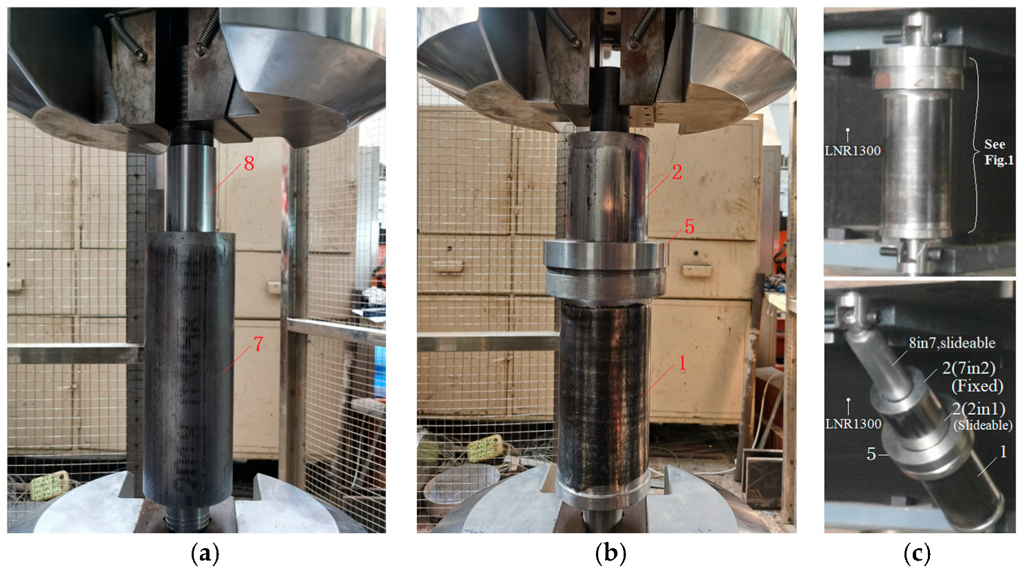
The purpose of this experiment is to quantify the parameters that affect friction force, such as the pre-tightening force (torque) on friction tiles, the type, the amplitude of loading, and loading velocity, and to obtain the optimal pre-tightening force combination. Figure 4a,b show the two friction damper tests, which are full-scale components. The first-stage damper can be installed within the second-stage (see also in Figure 1 and Figure 4c).
The test uses a MTS-311 electro-hydraulic servo fatigue testing machine at Beijing University of Technology. Since the maximum dynamic stroke of the machine is only 250 mm, it does not meet the requirements of the maximum extension displacement of 443 mm+ for the two dampers in series. Therefore, the assembled two-stage dampers are separated and subjected to static cyclic loading tests separately to determine the mechanical parameters and hysteresis loop characteristics.
The separate test is only used in experimental studies to determine the force–displacement curves of the damper at each stage, but it cannot reflect the changes in force at the instant of switching. This process can be observed, qualitatively analyzed, and judged through full-scale combined isolation bearing tests, and should also be taken into consideration when establishing a large displacement hysteresis model.
The preload torque is set at three levels for the two-stage dampers: 1.2, 1.4, and 1.6 Nm for the first stage damper, and 20, 22, and 24 N-m for the second one. Variable velocity (frequency) loading, amplitude loading, and fatigue tests are carried out. The first two types of loading were performed for three circles for each test, with loading frequency range from 0.02, 0.05, 0.1, 0.3, 0.5, and 1.0 Hz respectively; while the fatigue test on the dampers was conducted for 30 circles, with loading frequency of 0.04 Hz and amplitude of 60 mm. The low cycle fatigue test does not contain fatigue life test, aiming to verify whether the requirements of the technical standard [19] are met. Additional screws are installed at both ends of the specimen to accommodate the fixed clamps at the upper and lower ends of the machine (Figure 4). Before and after each loading condition, the temperature of the outer wall of the damper is recorded using an infrared thermometer.

2.2. Main Test Results

2.2.1. Different Pre-Tightened Forces and Variable Displacement Amplitude Tests

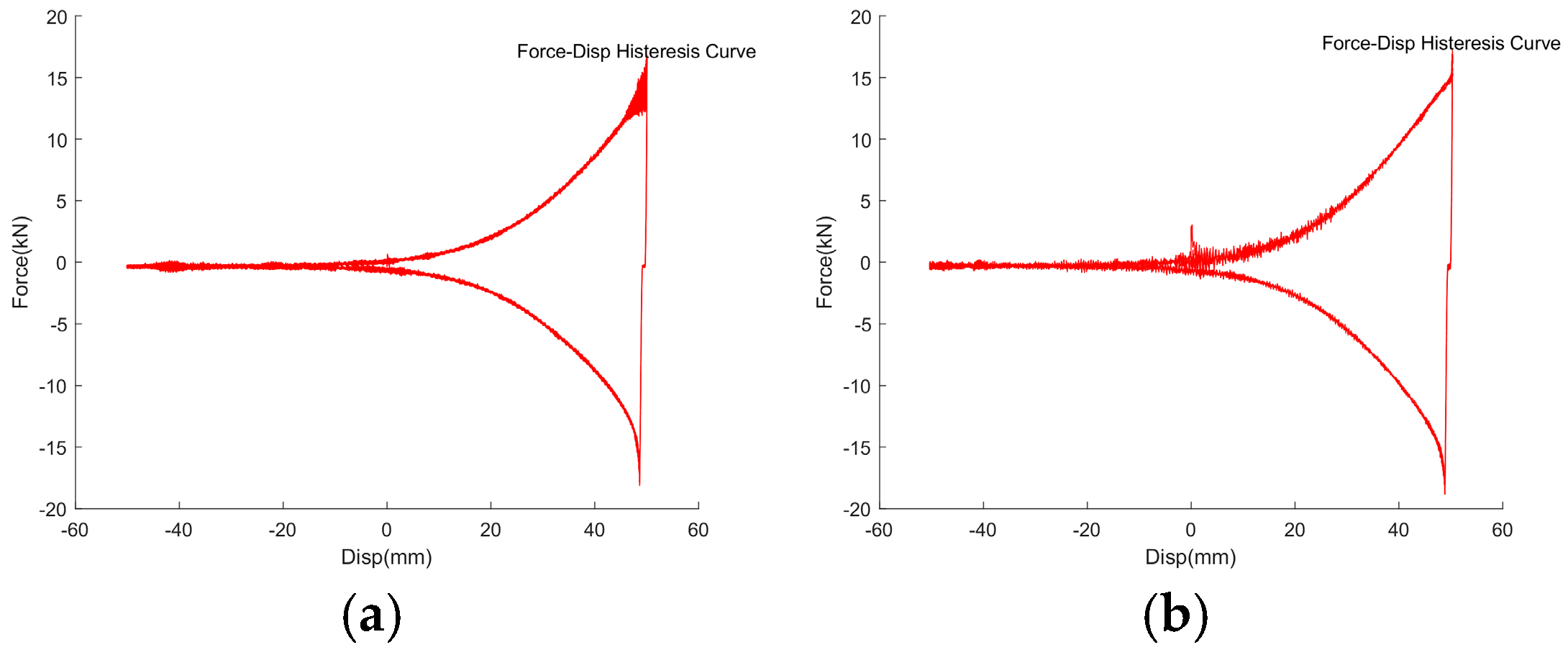
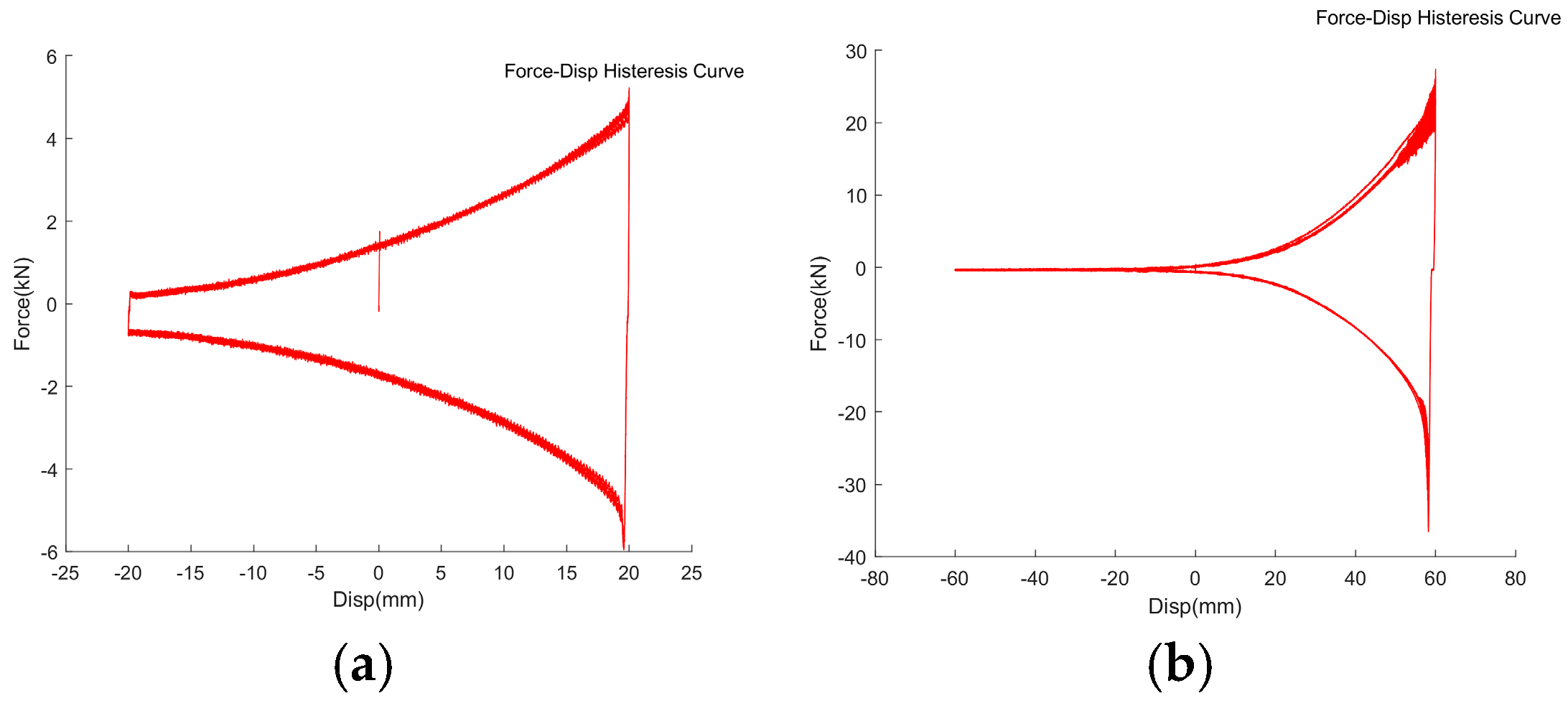
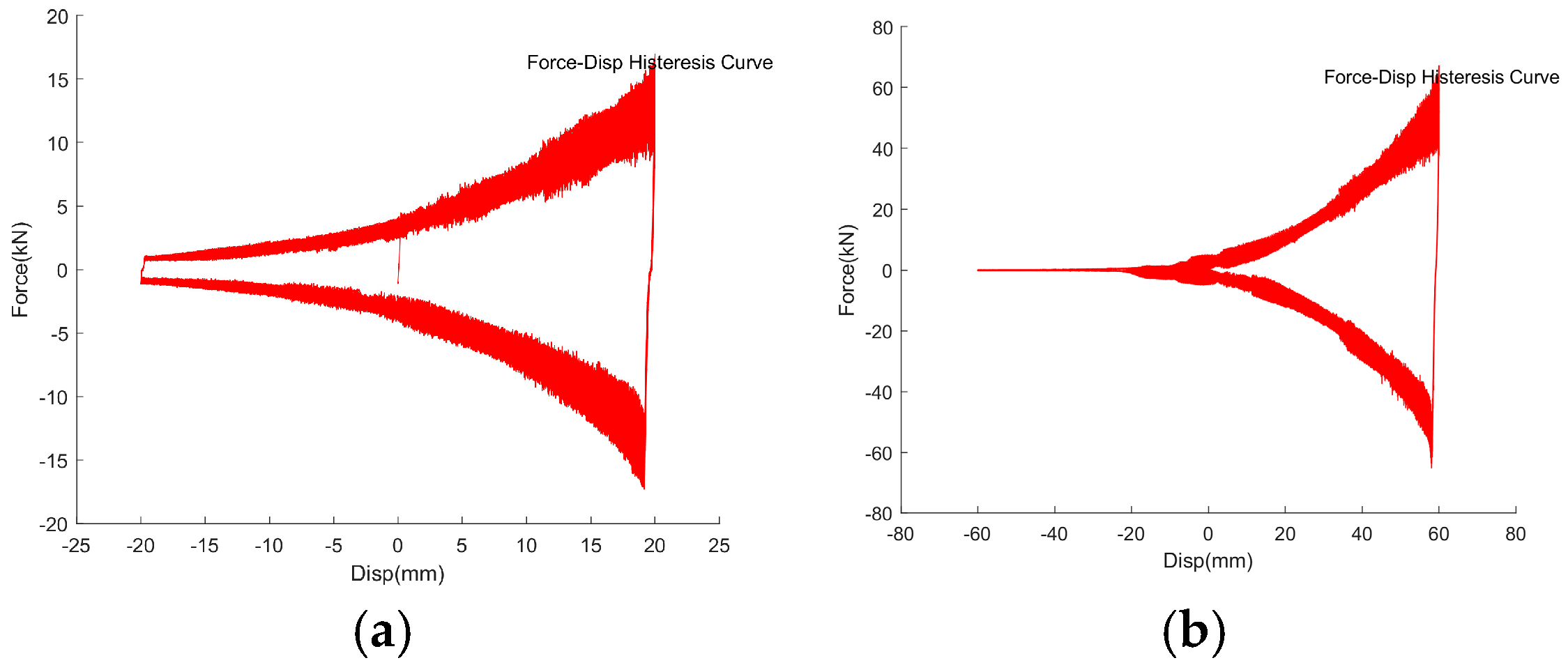
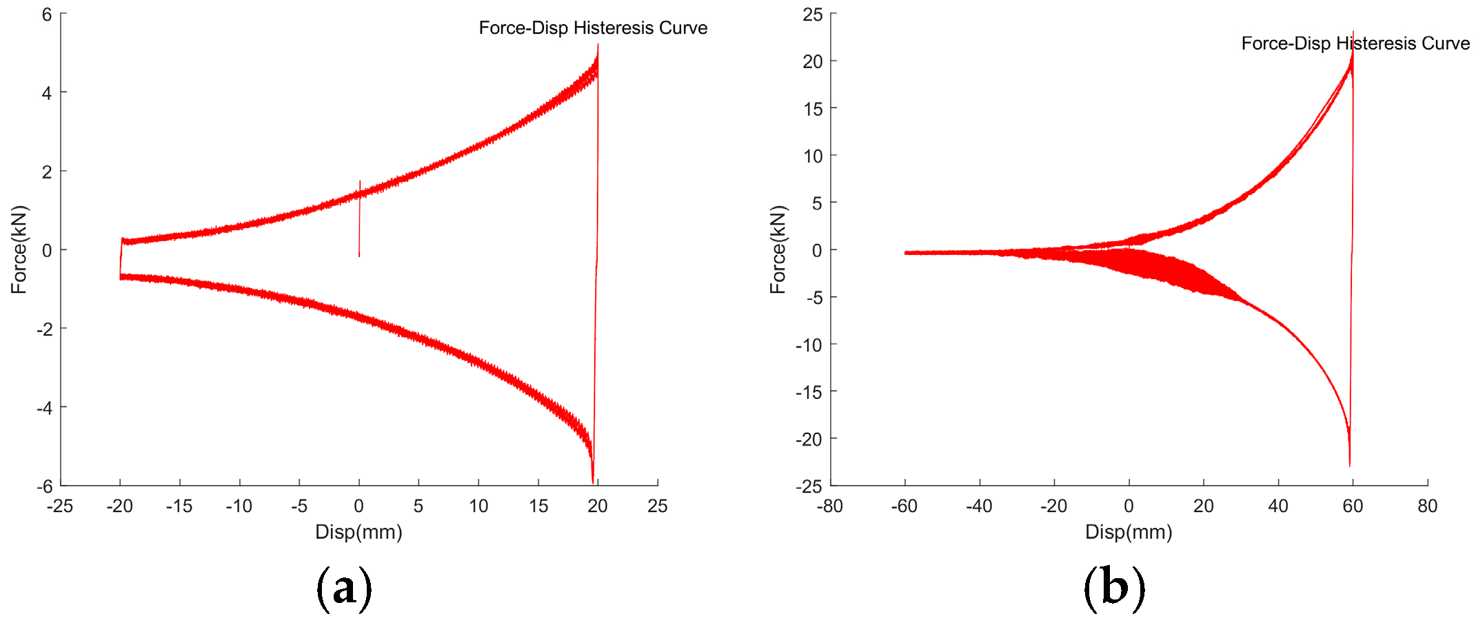
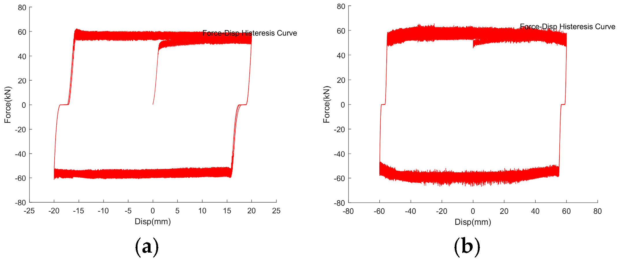
Figure 5 shows the axial F-Δ hysteresis curve of the first-stage damper in semi-metal tile under the 1.2 Nm pre-tightening torque of each bolt, with the amplitude of 20 and 60 mm and frequency of 0.02 Hz. Figure 6 shows the curve of the damper under the pre-tighten torque of 1.6 Nm with the same loading conditions. It can be seen that the hysteresis curve of the first stage friction damper is trumpet-like, and the force is related to the amplitude. The increase in the torque increases the noise.
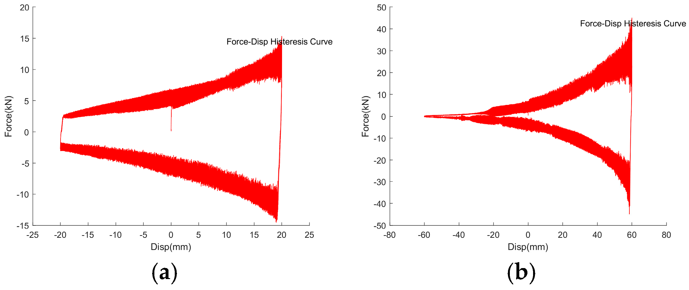
Figure 7 and Figure 8 show the test results of full-metal tile dampers compared with Figure 5 and Figure 6. It can be seen that the correlation between the friction force and the displacement amplitude of the full-metal tile and the influence law of the pre-tightened force are similar to those of the above-mentioned damper, but the main difference is, obviously, that the noise is louder and appears earlier.
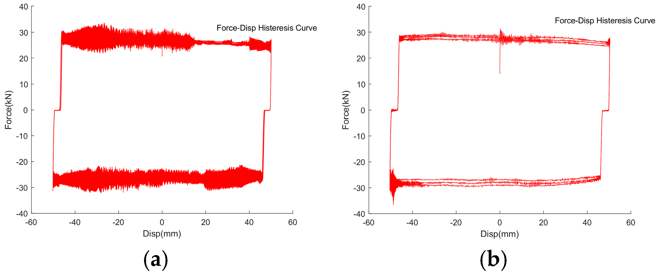
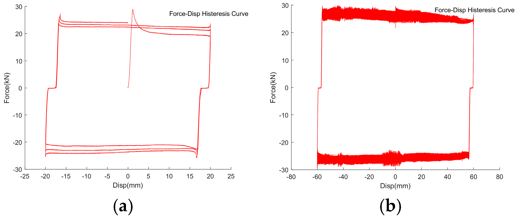
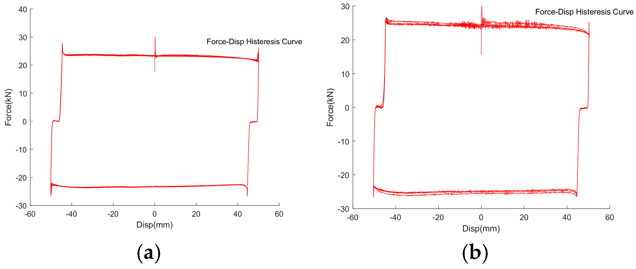
Figure 9 shows the F-Δ hysteresis curve of the semi-metal tiles of the second stage damper under the 20 Nm torque, with the amplitude of 20 and 60 mm and frequency of 0.02 Hz. Figure 10 shows the curve of the 24 Nm pre-tighten torque. It can be seen that the hysteretic curves are all of rectangular shape and that the friction force is basically not affected by the amplitude, but increases with the increase in the pre-tightening force. The increased torque also increases noise.
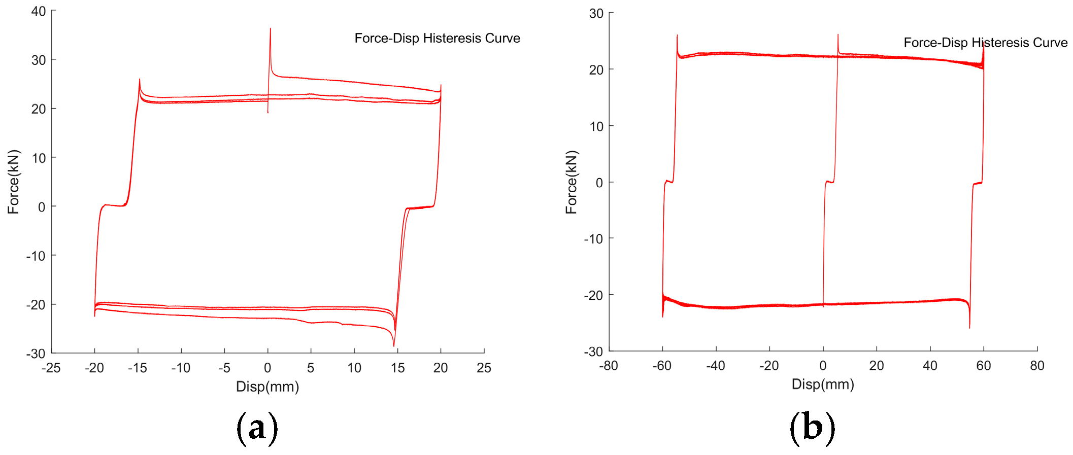
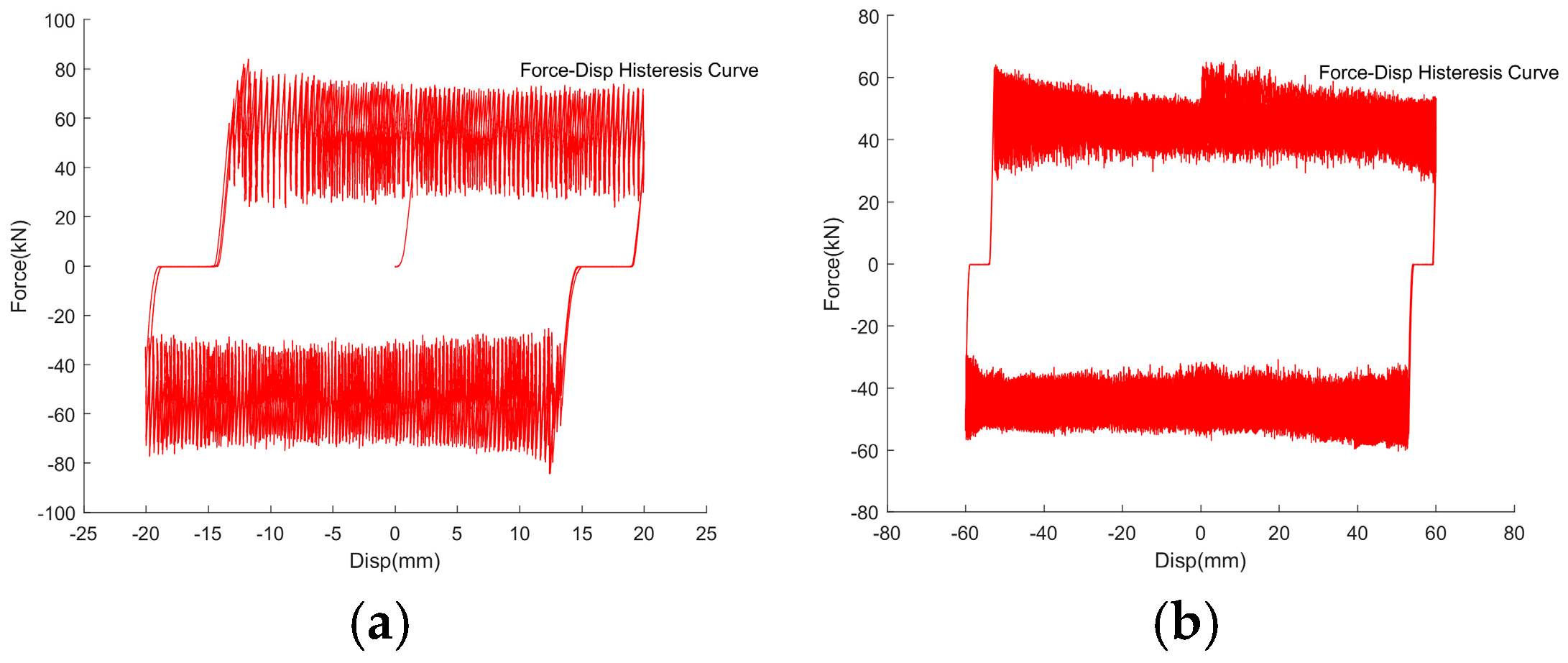
Figure 11 and Figure 12 show the results of full-metal tiles compared with Figure 9 and Figure 10. It can be seen that the influence of pre-tightening force on the relationship of friction and displacement is similar in the two different tile materials, but the main difference lies in the noise and friction amplitude. When the displacement reaches 60 mm or the preloading torque is 24 Nm, the noise increases, and the louder noise reduces the effective friction force significantly.

2.2.2. Variable Speed Loading Test

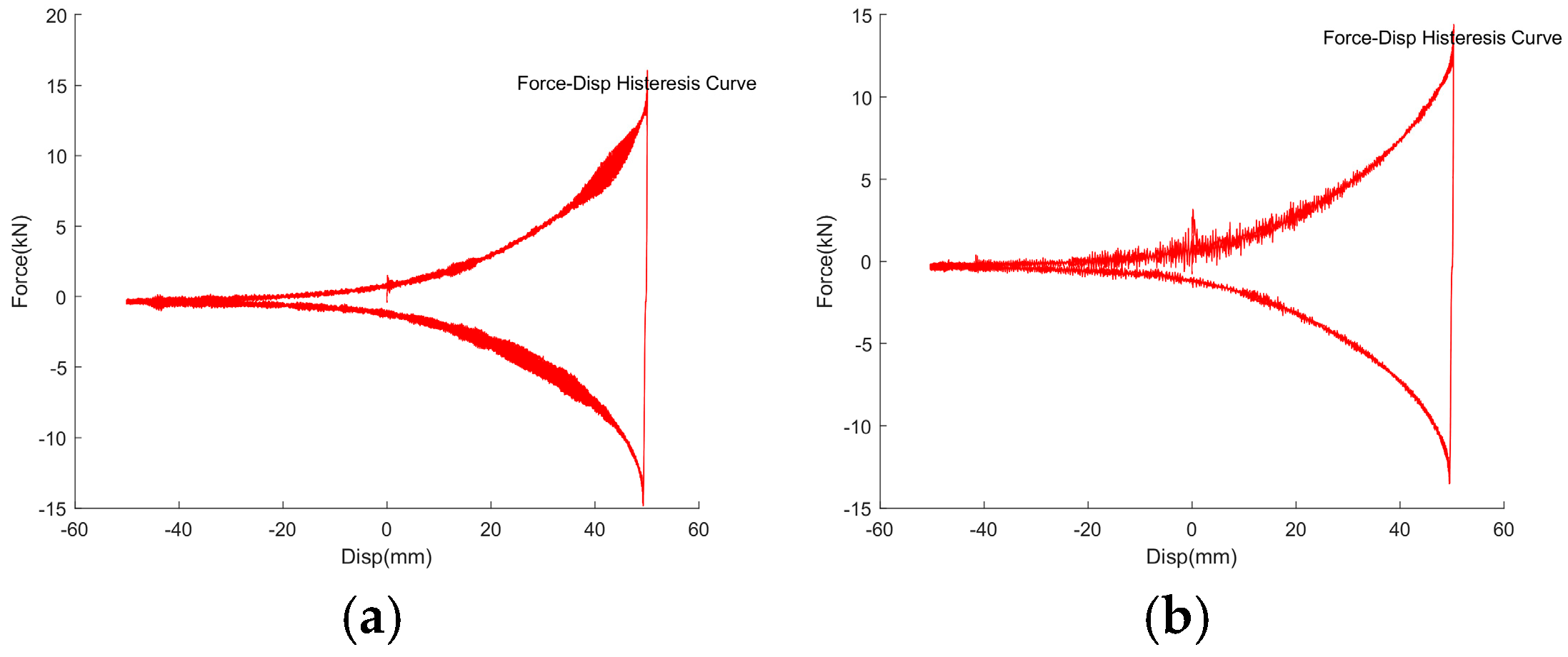
Figure 13 and Figure 14 show the F-Δ hysteresis curves of the 1st stage semi-metal and full-metal dampers at loading frequencies of 0.05 and 0.3 Hz respectively. The comparison shows that the loading frequency in this range has a little influence on the friction amplitude and curve shape of the two kinds of material with the same pre-tighten torque of 1.2 Nm.
Figure 15 and Figure 16 show the F-Δ hysteresis curves of the second semi-metal and full-metal dampers at loading frequencies of 0.05 and 0.3 Hz respectively. The comparison shows that under 20 Nm pre-tighten torque, the loading frequency in this range has almost little influence on the friction amplitude and curve shape of the two kinds of material, but the noise of the full-metal tile is larger than that of the former.

2.2.3. Discussion of the Influencing Factors

The first is the noise. Noise reduction is a necessary condition for friction dampers to work normally with energy consumption. From these tests, it can be seen that the value of preload and the friction material type have great influence on the noise. The selection of semi-metal tiles and applying low preload torque (1.2 Nm in the first stage and 20 Nm in the second stage) maintain low noise and reduce material loss in a wide range of loading amplitudes and speeds.
With the noise generated on the force–displacement hysteresis curve, the damper entity will produce high frequency vibration and make large disturbing noisy sound, indicating that the friction behavior may transit rapidly between static and dynamic friction (similar to the ABS of automobiles), due to the roughness on the contact surface. The damage caused by the noise and vibration to the friction tile has an adverse effect on the durability, output stability of the damper, and output effective friction force.
Through the noise discussions, combined with the experimental phenomena of the other research results [23,24], it can be inferred that the working mechanism of the friction tile has an evolutionary process, that is, from elastic friction to furrowing friction and elastoplastic friction mechanisms. This process mainly relates to the material type, compressive stress, and mechanical properties of the tile, and generally features in a compound friction state (that is, elastic, furrow, and elastoplastic exist at the same time). There are two internal factors that play a key role: one is the shape of the friction surface, the surface of the first-stage damper is gently tapered rod, and the second one is the equal section rod, so the two show hysteresis curve shapes in the macro differently. The other is the type of friction material: the metal tile’s hardness and elastic modulus are higher than that of the semi-metal tile’s, but the adhesion of the contact surface is low, so it is hard to enter elastic–plastic state (mainly elastic and furrow), along with the larger noise; the semi-metal tile has lower elastic modulus, better fit degree, stronger flexure adaptability, obvious elastoplastic performance, slightly higher or flat output friction than the former, and lower noise.
Based on the above analysis, considering that the full-metal friction tile damper may produce loud noise, as shown in Figure 6, Figure 8, Figure 10, Figure 12 and Figure 16, it is temporarily not used as the friction material for the combined seismic isolation bearing.
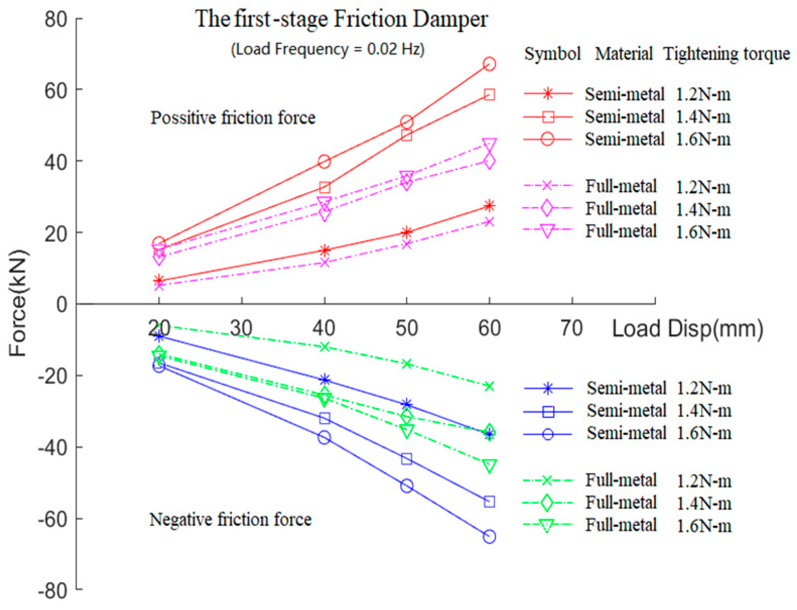
Secondly, the correlations are discussed here. Figure 17 shows the statistical relationship between the peak friction value and the load displacement amplitude of the 1st stage damper under different pre-tightened torque values. It can be seen that the peak friction force increases with the increase in amplitude and the preload, and the friction force of semi-metal tile is higher than that of full-metal friction tile. The reason for the amplitude correlation is that the central rod of the first-stage damper is a gently tapered rod, and the greater the displacement, the greater the working pressure on the friction tile, and thus the greater the friction force.
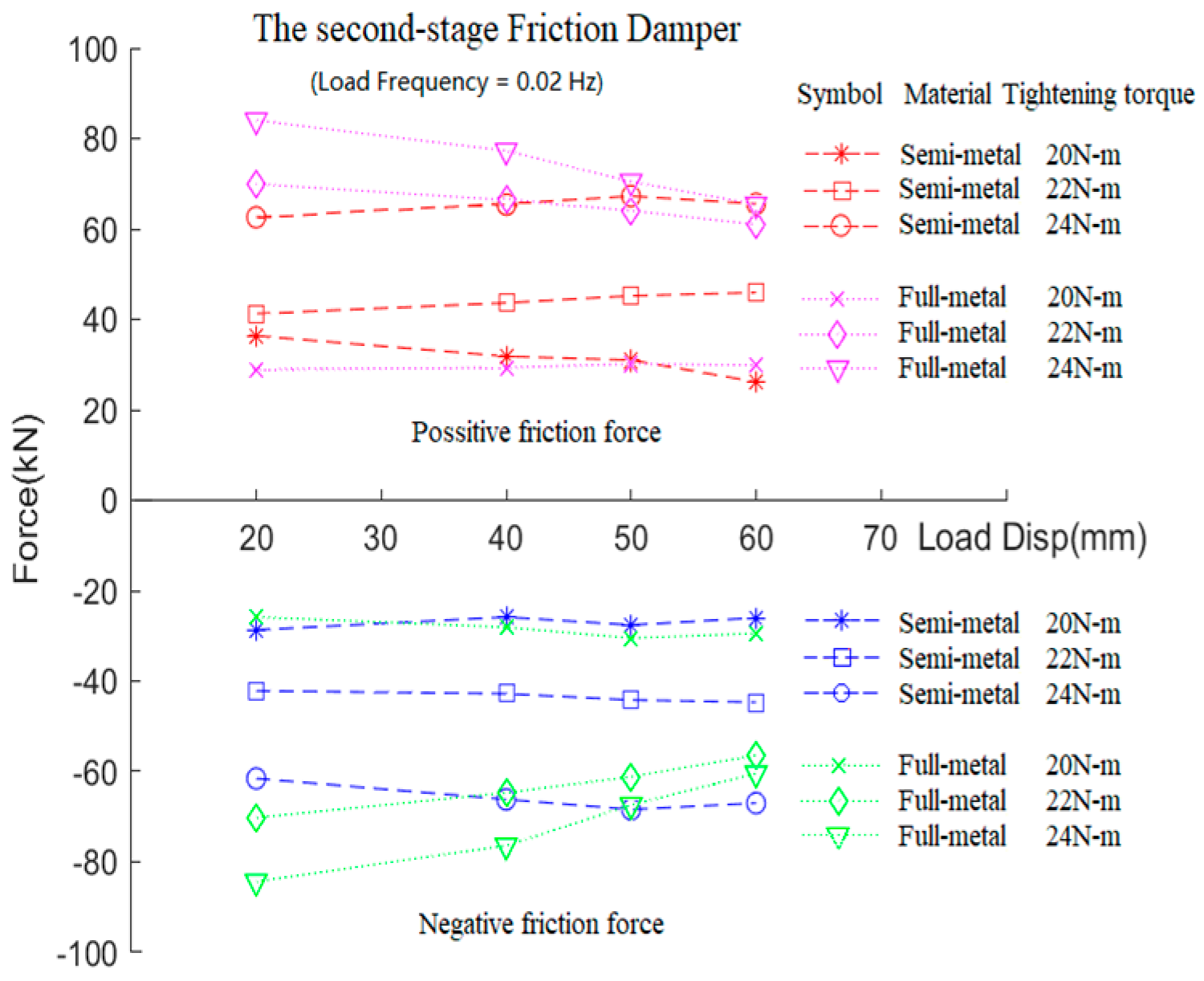
Figure 18 shows the statistical relationship between the peak friction force and the amplitude of the second damper with variable pre-tightened torque values. Generally, the friction force is not significantly affected by the amplitude, and the friction of semi-metal tiles is higher than that of full-metal tiles. The friction force increases with the increase in preload, but it is not proportional. Considering the variable amplitude tests are controlled by loading frequency (0.02 Hz), the tests with different amplitudes actually contain certain velocity effects. The influence of loading speed can also be confirmed from the following statistical results of fixed-amplitude tests with variable frequency loading (Figure 19 and Figure 20).
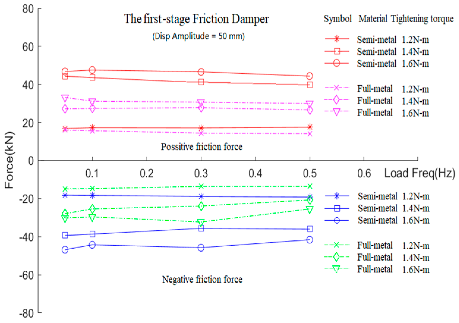
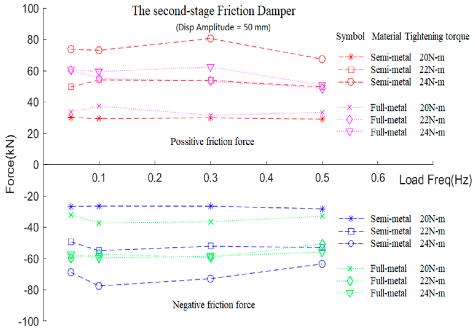
It can be seen from Figure 19 and Figure 20 that when the displacement amplitude is constant at 50 mm, the friction decreases slightly with the increase in loading speed at higher values of the pre-tighten torque. The increase in pre-tighten torque has an obvious effect, and the friction output of semi-metal tiles is higher than that of full-metal tiles.
It is worth noting that, as can be seen from Figure 17 and Figure 18, within the displacement amplitude of ±60 mm, the maximum output friction force of the first-stage damper with 1.4 and 1.6 N-m preloading torque is higher than that of the second-stage damper with 20 and 22 N-m preloading torque. The friction force of the first damper in full-metal with 1.4 and 1.6 N-m pre-tighten torque exceeds the friction output of the second damper with 20 N-m. Within this pre-tightening torque range, the series combination of the two-stage dampers can ensure that not only the first stage is pulled out first and then releases the second stage, but also when the load is reversing, the second stage is retracted first and then pushes the first stage back. This will ensure that the large displacement end presents a bone-shaped force–displacement curve, enabling the normal switching function of the damping to work.

2.2.4. Friction Tiles Wear Phenomenon

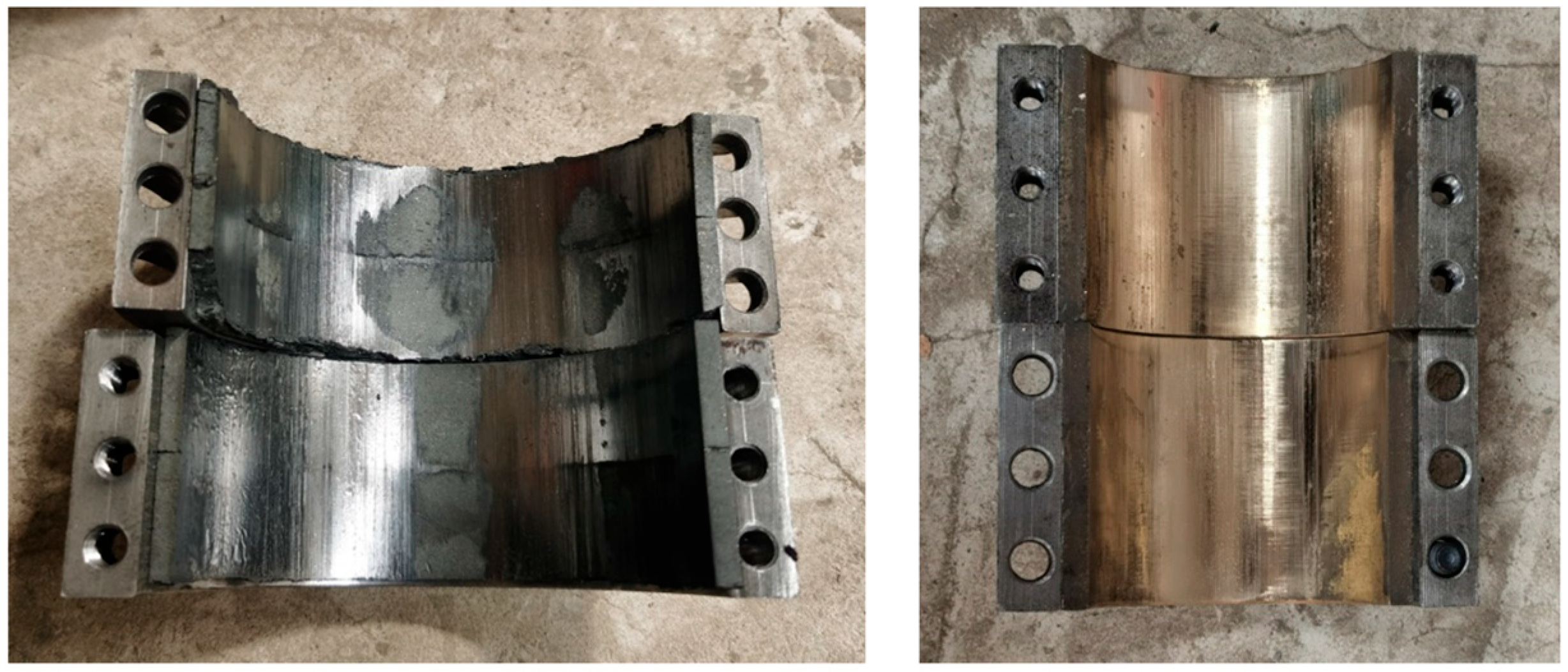
After the above tests, the two sets of the semi-metal friction tiles are worn, accompanied by more obvious furrowed scratches, and there are a few defects and cracks at the corners, but the overall shape remains comparatively intact. The wear is somewhat unevenly distributed, as shown in Figure 21. It is speculated that the reason might be due to the uneven compressive stress between the friction surfaces caused by the pre-tightened semi-circular retaining hoops, or it might be affected by the processing accuracy. Further structural improvements, such as thickening the retaining hoops, might be necessary.
The metal tiles have a slightly worn appearance with tiny furrowed scratches (see Figure 21 (right)), indicating a higher durability than that of semi-metal pieces. However, because there is a certain initial deviation between the two curved surfaces of the friction tile and the retaining ring, the pre-tightened bolt needs extra force to make it fit with the slide rod, which may lose certain pre-tightened stress. This may be the reason why the friction capacity is slightly lower than that of the semi-metal tile damper.

3. The Parameter Design Method of Friction Dampers

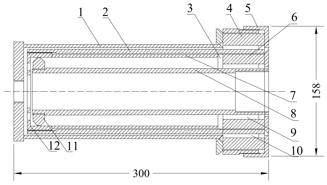
The two-stage cylindrical friction damper mainly consists of the inner cylinder (with its outer wall as the friction surface to form the first-stage friction damper), an outer cylinder, and the second-stage friction damper with the outer wall of the middle cylinder as the friction surface, besides the two sets of friction tiles with retaining hoops, totaling five main components (Figure 1). Adjustable preload is applied with the external retaining hoops to meet different friction bearing capacity requirements. The first-stage friction sliding rod is designed as a gently tapered cylinder rod (8 in Figure 1), while the second-stage sliding rod is designed as a cylindrical hollow tube (2 in Figure 1) with constant section. This arrangement ensures that the maximum friction bearing capacity output occurs at the large displacement end of the bearing (see the principles in Section 4.2.2 and Section 5). In this part, the internal forces and working conditions of the first-stage variable friction damper are mainly studied. The elastic mechanics analytical method is used for force analysis, and the calculation formulas for internal forces and displacements is derived to provide a calculation tool for the initial structural design. For the second-stage friction damper, its bearing capacity is independent of the sliding position and belongs to a conventional friction damper, so it will not be elaborated here.

3.1. Stress, Deformation and Force Analysis

3.1.1. Component Stress State

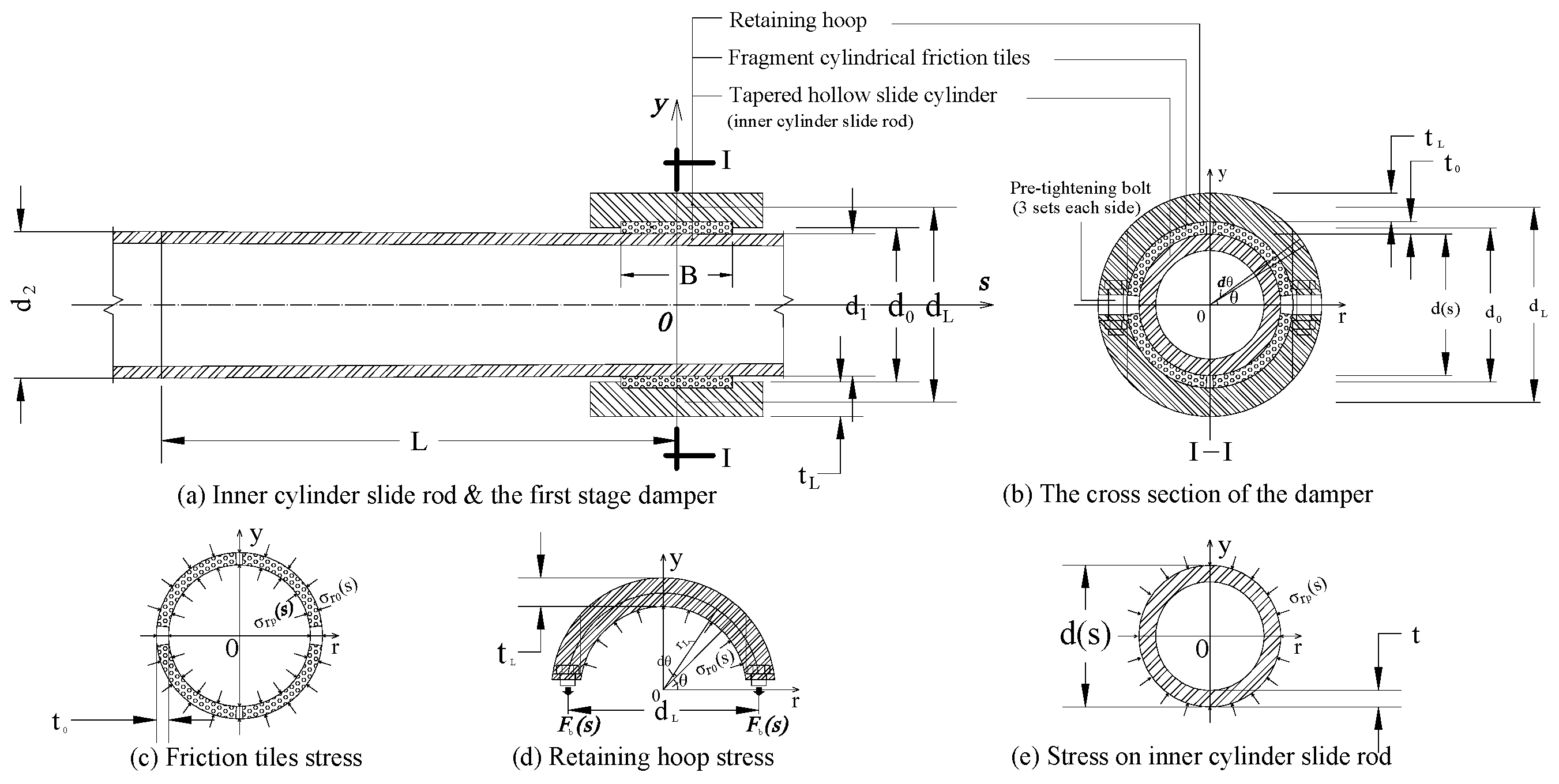
In this section, the force and deformation analysis is carried out using the analytical method to provide structural design calculation of dampers. Here, the calculating formula of a first-stage friction damper is briefly described. Figure 22 shows the damper’s structure, the cross-section, the separate bodies, and some parameters of the first-stage damper, and the radial stress transferred in between.
According to the stress state between the separate bodies in Figure 22, the internal stress and deformation can be obtained. The radial compression stress and deformation transmitted between the variable diameter rod and the friction tiles should consider the radial deformation compatibility. Since the central slide rod has a gently varying diameter and can slide along its longitudinal axis (Figure 22a), the compressive stress σr0, σrp, the pre-tightened force Fb and friction bearing capacity T are all functions of the sliding displacement s. The surface compressive stress on the center rod and the tightened force around it maintain a dynamic balance, and the friction between the center rod and the friction tiles supplies a dynamic friction bearing capacity T(s).
The stress of a section of the inner cylinder is shown in Figure 22e, with outer surface subjected to uniform compressive stress σrp from the friction tiles (Figure 22c), which keeps in balance with the tightening force of the retaining hoop (Figure 22d), and its solution belongs to the axisymmetric plane stress problem of the annular continuum.

3.1.2. Internal Force and Displacement Analysis

Here, the main analysis focuses on the radial stress and radial deformation caused by the diameter variation in the central tapered cylindrical rod during the sliding process.
1.
Internal pressure stress and radial deformation of the retaining hoop
The retaining hoop is composed of two semi-circles (Figure 22d) and is connected by pre-tightening bolts. Under the action of the pre-tightening force Fb, a radial compressive stress σr0 is exerted on the internal friction tiles, and at the same time, radial deformations DLr0 and DLθ0 exist. According to the balance and physical conditions:
F b = B 2 0 π σ r 0 ( d L 0 t L ) 2 sin θ d θ = 0.5 B ( d L 0 t L ) σ r 0
where Fb represents the unilateral preload force of the bolts (including the preload); B is the width of the friction tiles; dL0 is the inner diameter of the retaining hoop; tL is the thickness of the retaining hoop:
D L r 0 = 0 t L 1 ρ t L σ r 0 E d ρ = t L 2 E σ r 0
where E represents the elastic modulus of steel material.
Under the action of preload force, the split retaining hoop generates circumferential tensile stress σθ and radial deformation DLθ0. Ignoring the influence of higher-order effects, we obtain:
D L θ 0 = d L 0 2 2 t L E σ r 0
2.
Internal and external compressive stresses and radial deformation of the friction tiles
As shown in Figure 22c, the pre-tightening of the retaining hoop generates compressive stresses σr0 and σrp on the outer and inner surface of the friction tiles. Since the friction tiles are of a multi-petal separated structure, the calculation of internal forces and displacements only involves equilibrium and physical conditions. The radial deformation Df0 generated by the above compressive stresses can be calculated using Equation (4):
σ r p = d 0 + t 0 d 0 t 0 σ r 0
where d0 is the average diameter of the friction tiles and t0 is the thickness of the friction tiles.
D f 0 = t 0 d 0 ( d 0 + t 0 ) E 0 σ r p
where E0 is the elastic modulus of friction material.
3.
Deformation caused by the tensioning effect of the pre-tightened bolts
The pre-tightening bolts that connect the upper and lower half-circular retaining hoops tighten the retaining hoop itself under the action of the pre-tightening torque. The deformation of these hoops can be converted into an average radial displacement, which can be calculated according to Equation (6):
D b r = B d L 0 π A b E L b σ r 0
where Lb and Ab represent the effective length and cross-sectional area of the pre-tightening bolt respectively.
4.
Solution for radial deformation and stress of the inner cylinder slide rod
The stress state of a section of the inner cylinder rod is shown in Figure 22e. The outer side of the cylinder wall is subjected to uniform compressive stress σrp transmitted from the friction hoops. The solution to this problem belongs to axisymmetric plane stress problem of a circular continuous body.
Based on elastic theory [33] the stress function Φ(ρ,θ) in polar coordinates satisfies compatibility Equation (7):
2 ρ 2 + 1 ρ ρ + 1 ρ 2 2 θ 2 2 Φ = 0
For axisymmetric problems, the stress function Φ(ρ,θ) can be expressed as a function of the radial coordinate ρ, that is, Φ(ρ,θ) = Φ(ρ).
Thus, the solution of the polar coordinate stress function of the cylinder that satisfies the compatibility Equation (7) is as shown in Equation (8). Under the action of uniformly distributed external pressure, the boundary conditions (9) are introduced. Combined with the single-valued displacement condition and the force boundary condition (q1 = 0, q2 = σrp in Figure 22e) of this case, the Lamé solution obtained is shown in Equation (10).
σ ρ = A ρ 2 + B ( 1 + l n ρ ) + 2 C σ θ = A ρ 2 + B ( 3 + 2 l n ρ ) + 2 C τ ρ θ = τ θ ρ = 0
where A, B, and C are undetermined constants, which are determined by the boundary conditions and displacement single value.
τ ρ θ ( ρ = r ) = 0 ,                     τ ρ θ ( ρ = R ) = 0 , σ ρ ( ρ = r ) = q 1 = 0 ,                 σ ρ ( ρ = R ) = q 2 = σ r p
σ ρ = 1 r 2 ρ 2 1 r 2 R 2 σ r p σ θ = 1 + r 2 ρ 2 1 r 2 R 2 σ r p
where r is the inner radius of the cylinder rod, r = d/2 t, t is the wall thickness, d is the outer diameter of the cylinder (see Figure 22e), R is the outer radius, and R = d/2. The outer diameter d of the central tapered cylinder rod will change when the rod slides along the longitudinal axis s (Figure 22a).
By introducing physical conditions and single displacement condition, the radial displacement of the cylinder wall corresponding to the above stress solution is:
D ρ ρ = R = R 1 ν R 2 + 1 + ν r 2 R 2 r 2 σ r p E
where ν is Poisson’s ratio = 0.30. Note that σr0 and σrp are interchangeable based on Equation (4).
5.
Total radial deformation
The total radial deformation Df caused by the above reasons can be calculated via Equation (12):
D f = D f 0 + D L r 0 + D L θ 0 + D b r + D ρ ( ρ = R )
where Df0, DLr0, D0, Dbr, and Dρ are the radial deformation of the friction tile (see Equation (5)), the radial deformation of the retaining hoop produced by the compressive stress σr0 and circumferential stress σθ due to the pre-tighten force Fb (Equations (2) and (3)), the converted average radial deformation by the pre-tightened connection bolts (Equation (6)), and that of the cylinder rod in Equation (11) as well.

3.2. Calculation for Confining Pressure and Friction Force of the Sliding Cylinder Rod

3.2.1. Confining Pressure

When the tapered rod slides along the s-axis, its diameter changes by Δd(s):
d s = d 1 + Δ d s = d 1 + d 2 d 1 L s
where d1 and d2 are respectively the minimum and maximum diameters within the length L of the working section of the central tapered rod, as shown in Figure 22a.
Because the outer diameter of the tapered cylinder is always in contact with the inner surface of friction tiles, the radial deformation of the two is coordinated at the contact surface, which can be understood as the radial expansion of the center cylinder rod is equal to the total radial deformation of each layer ring sleeve tightly covered outside it. Therefore, Δd(s) = 2Df, the formulas for calculating the slide displacement s, the compressive stress of the friction tiles, and the radial deformation can be established. For example, the specific confining pressure to the central tapered rod σrp can be calculated according to Equation (14):
σ r p ( x ) = 0.5 d 0 + t 0 E d 2 d 1 s L E E 0 t 0 d 0 + t L 2 + d L 0 2 2 t L + B d L 0 L b π A b d 0 t 0 + d d 2 2 1 + ν ) t ( d t ) 4 d t t ( d 0 + t 0 )
where E and E0 are the elastic moduli for steel and friction material respectively, dL0 is the initial diameter value of the retaining hoop, Lb and Ab are the length and the cross-section area of the pre-tightening bolt, d = d(s) is the outside diameter of the inner cylinder slide rod, and the function of slide displacement s; the other parameters are shown in Figure 22.
Equation (14) can be used to calculate the confining pressure change in the tapered rod caused by the sliding displacement s. The remaining contact compressive stress, friction tile thickness, retaining hoop thickness, and pre-tightening bolt tension force change can also be replaced by σrp for progressive calculation.

3.2.2. Frictional Bearing Capacity

Citing the mechanical friction theory [33,34], when the central rod slides a distance s, the total tensile capacity T(s) (in longitudinal axis) is equal to the static friction capacity plus dynamic force calculated with the contact area of the friction tiles, and the compressive stress σrp and the friction coefficient can be determined by the tests.
T s = T 0 + Δ T s = μ 0 F 0 + π μ s ˙ d s B σ r p ( s )
where μ0 represents static friction coefficient, with a range of 0.1~0.4; μ( s ˙ ) represents dynamic friction coefficient, with a range of 0.1~0.3; F0 is the preload force of the friction tiles; and d(s) and B are as mentioned above. The static and dynamic friction coefficients depend on the preload force, working hoop pressure, loading speed, etc. Other parameters, based on material tests, the steel, E = 2.0 × 10⁵ MPa, the semi-metal friction material, E0 = 6000 MPa, and compressive yield strength, 35 MPa.

3.2.3. Shear Resistance Capacity

The shear force contributed by the friction dampers in the combined isolation bearing, in addition to the aforementioned tension and compression capacity T(s), is also affected by the shear angle of the isolation bearing and the shear loading velocity. The following will discuss these aspects respectively.
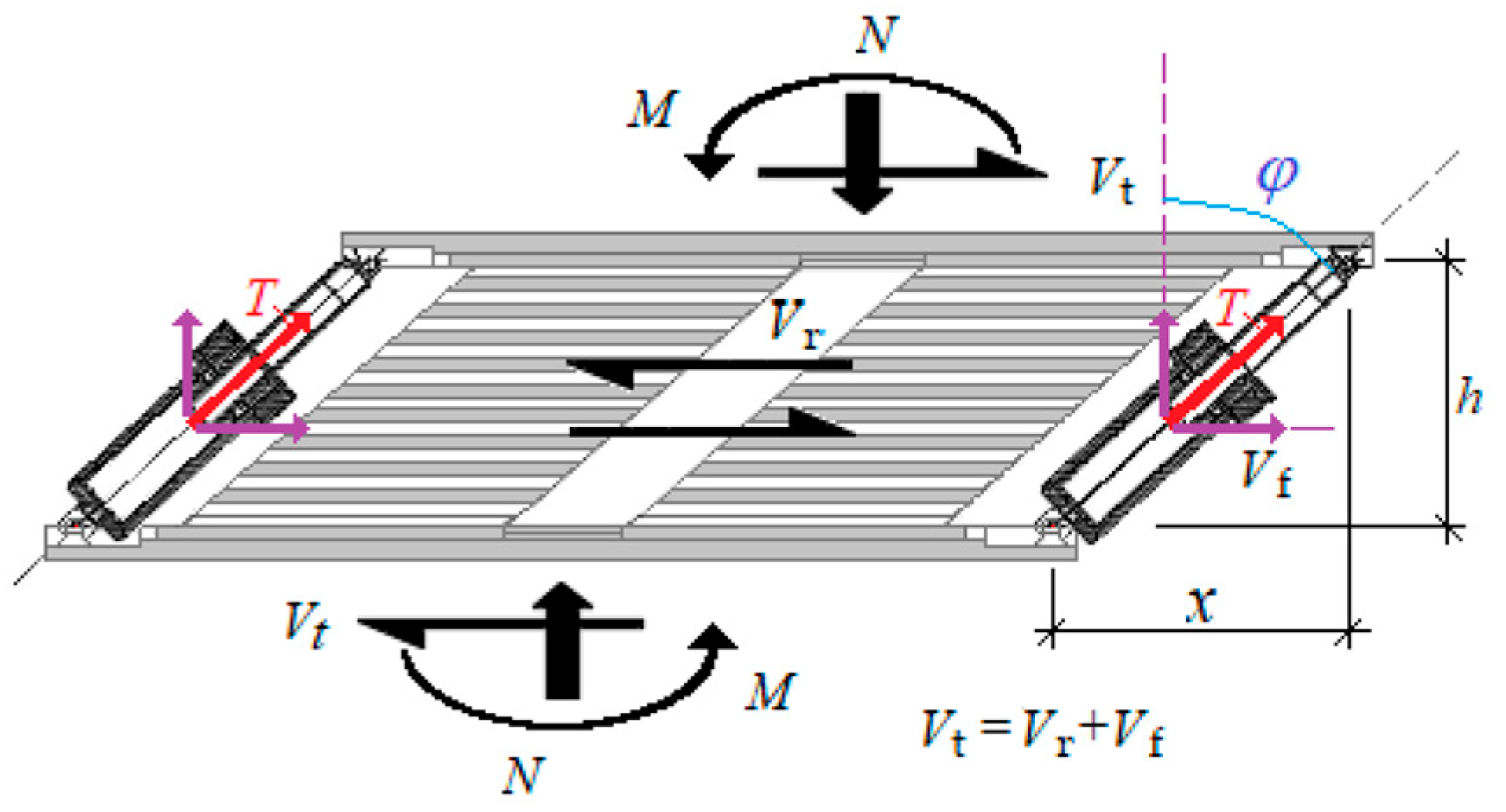
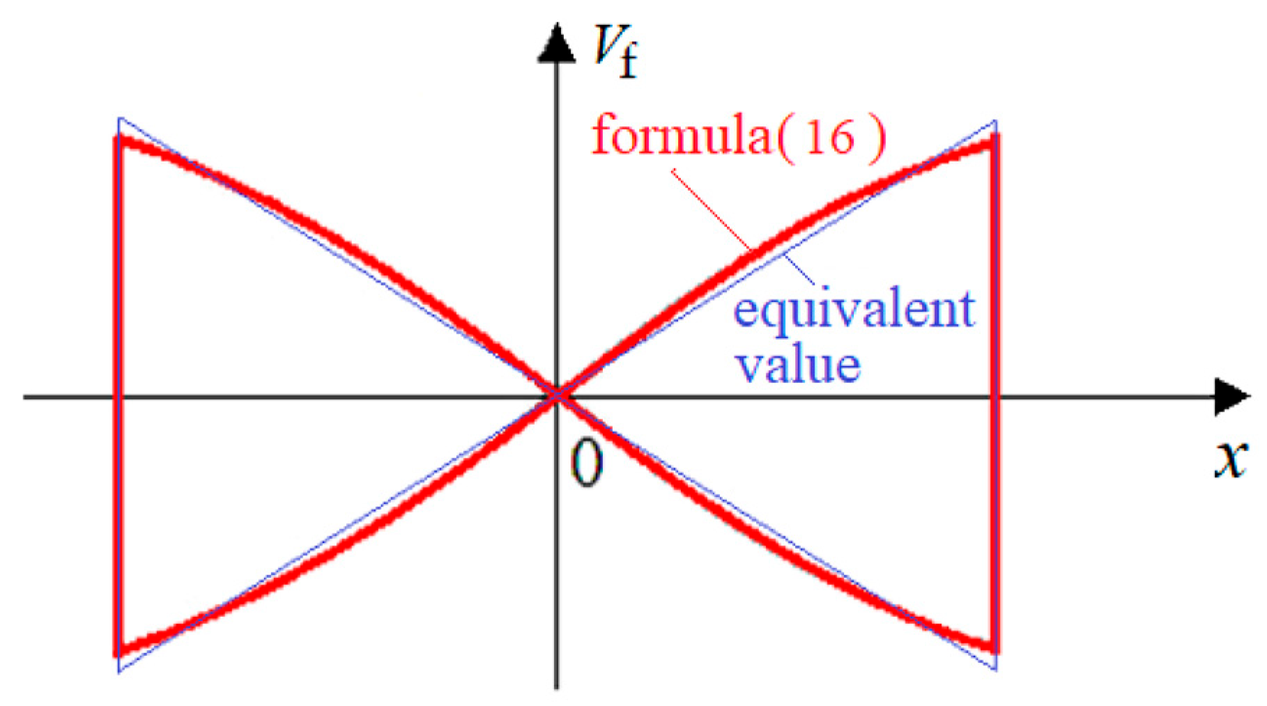
Shear angle: The friction damper is hinged around the LNR perimeter. Its axial friction force T forms an angle with the horizontal shear force Vf (i.e., the shear angle = π/2 − φ), as shown in Figure 23 (schematic diagram). The relationship between the shear force Vf and the shear displacement x is given by Equation (16). If Ti is assumed to be a constant, the relationship curve between Vf and x is as shown in Figure 24 (qualitative graph). The relationship between the shear displacement x and the axial displacement s is given by Equation (17). It can be seen that, due to the connection structure, the output of the shear force reaches its peak at the large displacement end, but it is close to zero at the zero shear displacement point.
V f = i = 1 n T i s s i n [ a r c t a n x h ] = i = 1 n T i ( s ) 1 + c t a n 2 ( φ )  
where n represents the number of friction dampers.
x = ± ( h + s ) 2 h 2
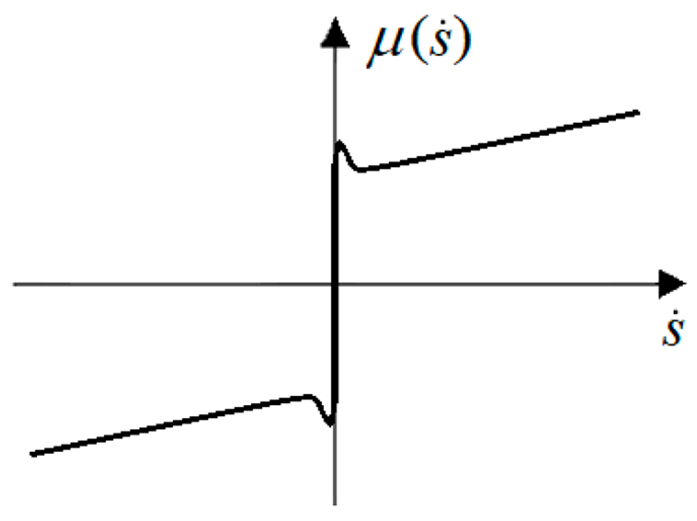
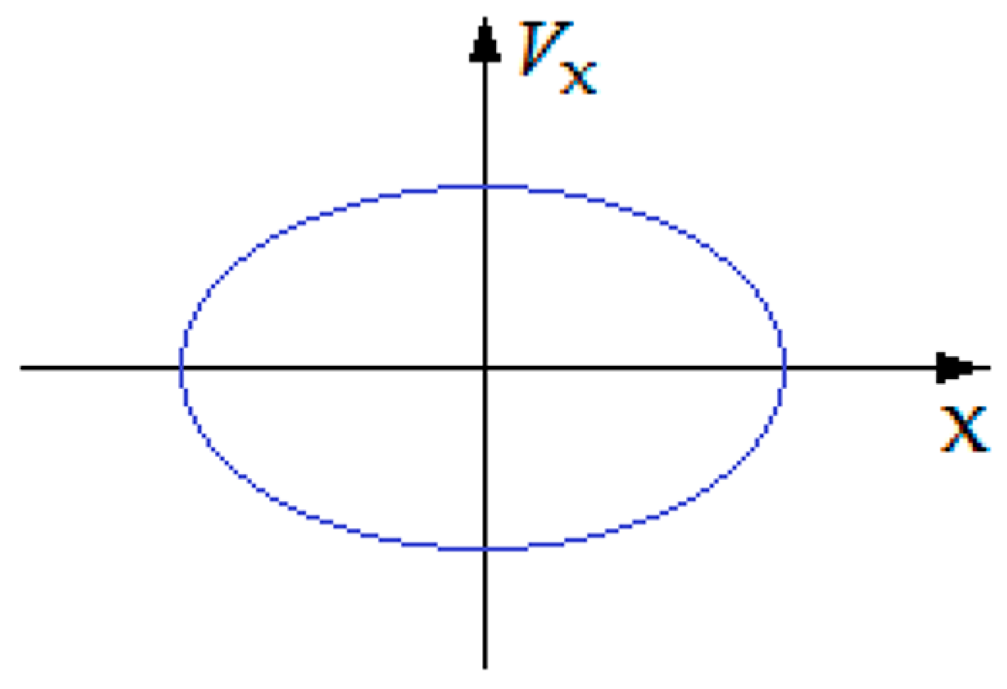
Loading velocity: The loading velocity has a certain influence on the friction coefficient or friction force [34,35], as shown in Figure 25 (qualitative graph). During the cyclic loading process of compression–shear of the isolation bearing, the loading velocity at different shear displacements x is variable (such as trigonometric function loaded, Figure 26, qualitative graph). From this, it can be seen that at the maximum shear displacement end of the isolation bearing, the dynamic friction coefficient is at a low value, but when the reverse loading begins, the shear motion of the bearing needs to overcome the static friction and generates a peak similar to that shown in Figure 25.
Taking into account the influence of the output force T of the composite friction damper, the LNR shear angle and the loading velocity, with the help of the modern friction theory that can consider static friction, Coulomb friction and viscous friction [34,35], it is suggested that the shear friction bearing capacity of the combined isolation bearing be expressed as follows:
V t = V r + V f = V r + α i = 1 n T i 0 s i n ( φ ) + β i = 1 n μ s ˙ T i ( s ) s i n ( φ )
where Vr represents the shear resistance of LNR (Figure 23), and coefficients α and β respectively represent the coefficients of the contribution of static and dynamic friction to the shear bearing capacity. Due to the influence of multiple factors such as the surface shape of the friction plate, the compressive stress level, the elastoplastic property of the friction material, the shear angle, and the loading speed, as well as deviations caused by processing accuracy, mechanical clearance, loading and measurement accuracy, it is difficult to conduct single-factor quantitative study for each factor. Therefore, it is recommended to comprehensively reflect these two parameters α and β. Their values can be statistically analyzed based on the compressive shear test results of the combined bearings and calculated considering a certain level of reliability.

4. Test of the Combined Seismic Isolation Bearing

4.1. Test Method of the Bearings

A comparative experimental study of LNRF and LNR is conducted through static cyclic compressional shear loading tests, mainly including the research on mechanical properties and their influencing factors, such as the stiffness, bearing capacity, influencing factors, as well as the energy dissipation capacity, hysteresis curve, damping ratio, and fatigue performance of the combined isolation bearings, etc.
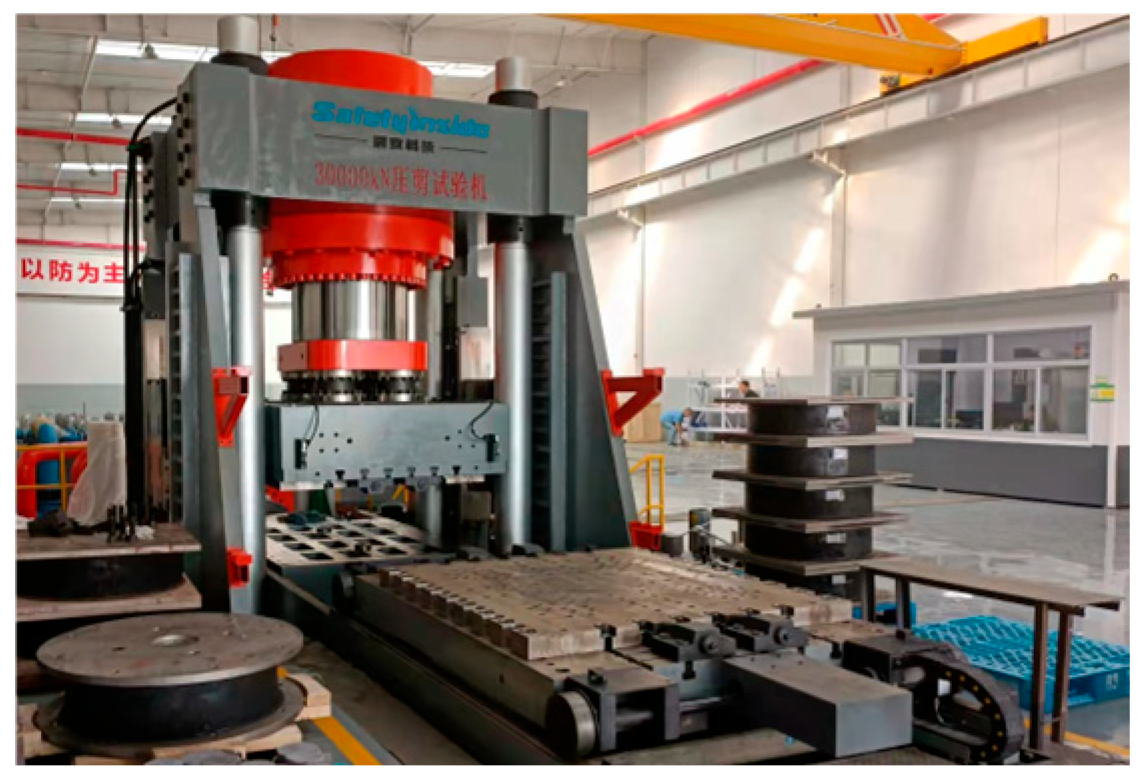
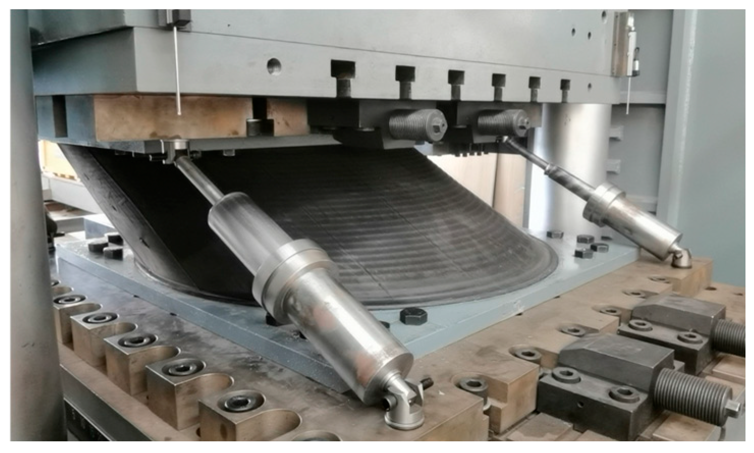
The test is completed on the large compression–shear testing machine of Quake Safe Technologies Co., LTD (Figure 27). The rating capacity of the machine is the maximum pressure of 30,000 kN, horizontal force of ±8000 kN, and vertical and horizontal stroke of 800 mm (±400 mm) and ±1000 mm respectively. The machine can especially carry out the isolation bearing’s test, which is characterized by the realization of vertical and horizontal combined loading, and the realization of force and displacement control, and maintaining the translation condition of the upper and lower end plates of the isolation bearing during the test. The loading frequency of horizontal shear tests is set at 0.005–0.006 Hz, while the other cyclic tests (including the vertical cyclic tests, horizontal loading frequency influence tests, and the fatigue tests, etc.) are set at 0.02–0.03 Hz. The fatigue tests are conducted with 30 circles, the other tests are conducted with three circles. The sampling frequency is set to 20 Hz or more. Figure 28 and Figure 29 show the laminated natural rubber bearing with friction dampers (LNRF) on the testing machine. The LNR and LNRF tests have been carried out respectively. The diameter of LNR is 1300 mm, with the total thickness of the rubber being 239 mm. LNRF uses the same specification, LNR, and is equipped with four two-stage friction dampers. Each damper has a bearing capacity of 40 kN (semi-metallic tiles). The tightening torque of the bolts is set at 1.2 Nm (first stage) and 20 Nm (second stage) respectively.

4.2. The Main Test Results

4.2.1. Vertical Loading Tests

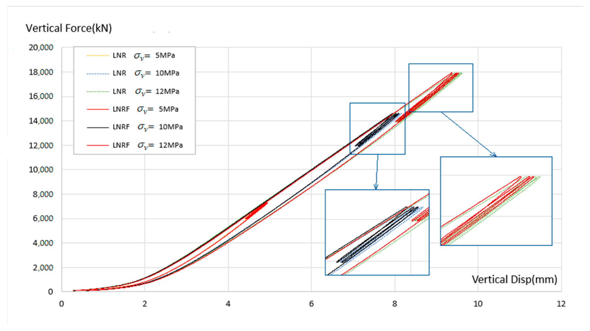
Figure 30 shows the hysteresis curves obtained by the compressional tests of LNR and LNRF under three working compressive stress levels (5, 10, and 12 MPa), in which the cyclic range of vertical loading stress corresponding to each level is ±0.5, ±1.0, and ±1.5 MPa respectively. Three cycles per working condition are tested.
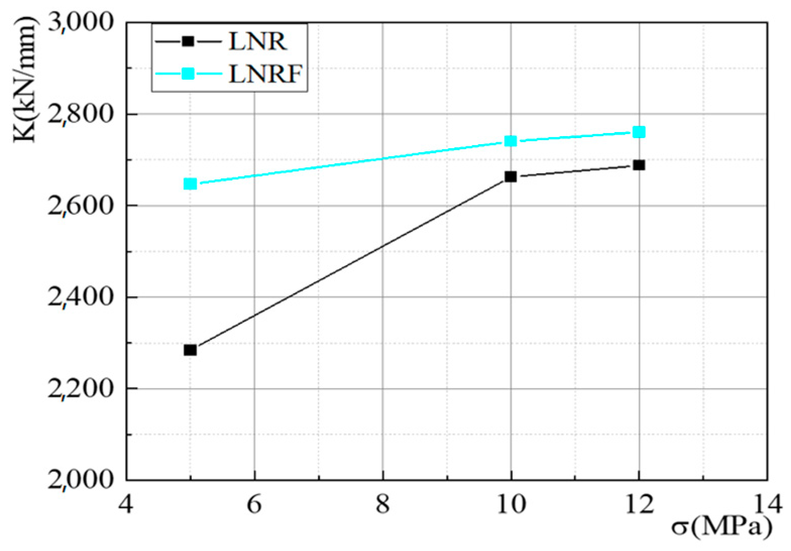
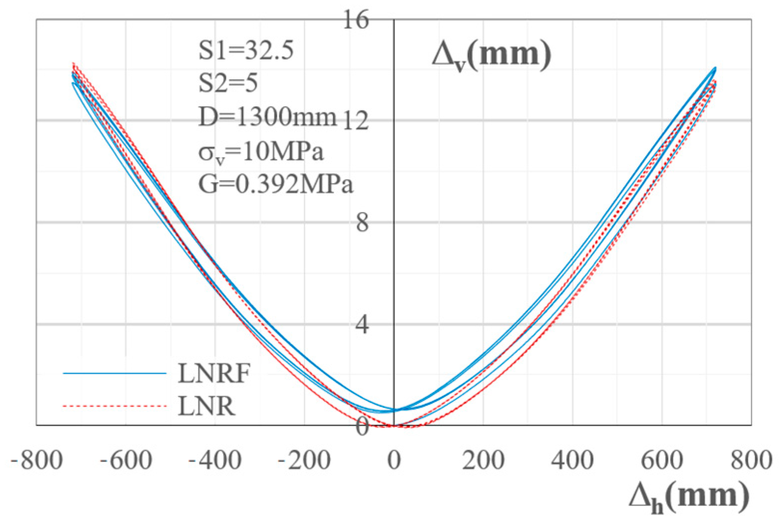
As can be seen from Figure 30, when the compressive stress is relatively small, the hysteresis curves of LNRF and LNR under cyclic loading are almost consistent. When the compressive stress is great, the LNRF hysteresis force with same displacement is slightly higher than LNR. The data show (Figure 31) that when the compressive stress is 10 and 12 MPa, the average vertical compression stiffness of LNRF is 2~3% higher than that of LNR. After three cycles of loading, the stiffness degradation of both kinds of bearings exists, but the degradation of LNRF is 3~5% smaller than that of LNR. The relationship between the vertical and the horizontal displacement shown in Figure 32 indicates that the two-way displacement curves of the two types of bearings are almost identical, suggesting that the additional friction dampers have not altered the deformation characteristics of the LNR.

4.2.2. Horizontal Loading Test Results

1.
Compressive stress correlation
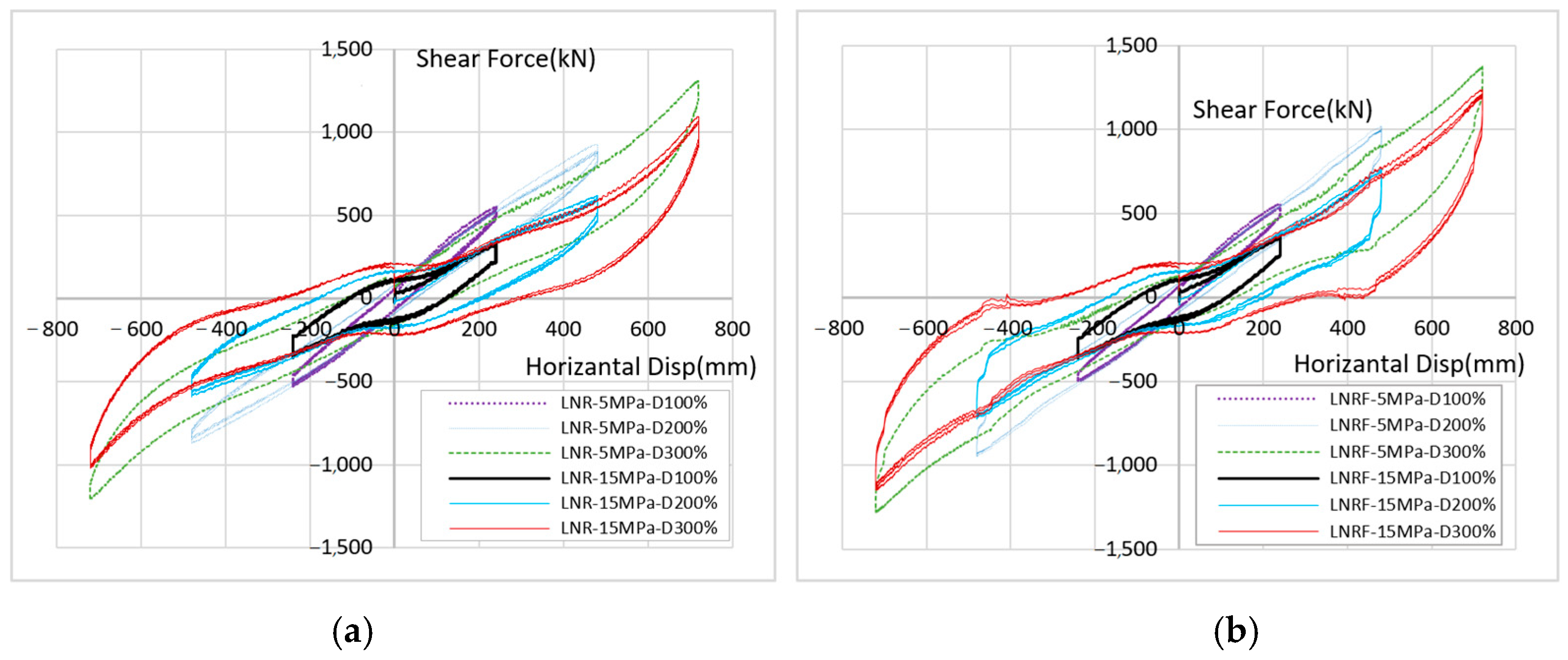
Figure 33 shows the V-Δ hysteresis curves of the two bearings with working stresses of 5 and 15 MPa respectively. The self-comparison of each bearing shows that the lateral stiffness decreases with the increase in compressive stress. When the two bearings are compared with each other, the hysteresis curve’s shape is similar, but the slicing force of LNRF is slightly smaller, and helps improve the seismic isolation effect. It is estimated that the friction damper shares the vertical pressure of the rubber bearing when the bearing displacement is small. When the shear displacement increases, the stiffness reduction in LNR is apparently influenced more by the vertical stress than that of LNRF. It is judged that the contribution of friction dampers to the horizontal stiffness degradation plays a compensatory effect.
Statistics show that the loading stiffness of LNR at 15 MPa is reduced to 72.63% (with shear angle of γ = 100%), 63.55% (200%), and 80.66% (300%) compared to that at 5 MPa; correspondingly, the stiffness of LNRF at 15 MPa is reduced to 73.62% (γ = 100%), 73.62% (200%), and 90.64% (300%) compared to that at 5 MPa. This indicates that the reduction in stiffness caused by the compressive stress on LNRF is smaller than that of the LNR bearing, with an average value of 9.70%.
2.
Influence of σv and γ on energy consumption
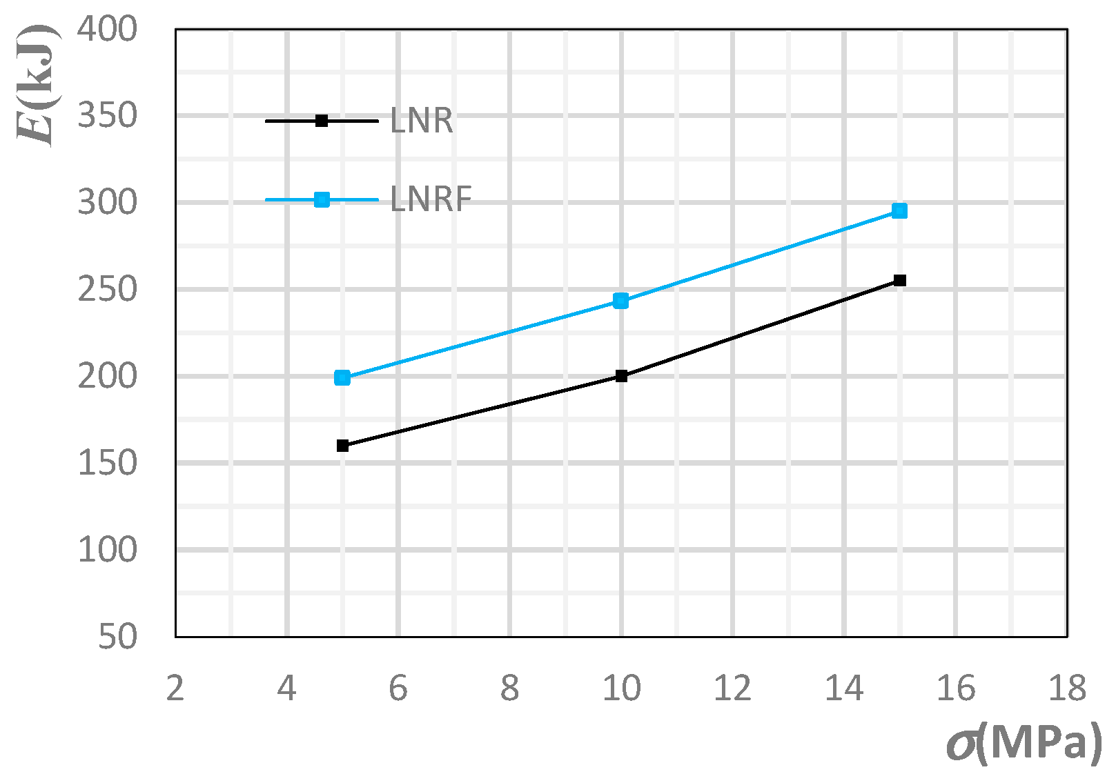
Figure 34 shows the statistical average curve of the compressive stress influence on dissipated energy of the two kinds of bearing. Obviously, the energy dissipating capacity of LNRF is greater than that of LNR, but the increasing slope with the compressive stress is very close to that of LNR within this range.
Figure 35 shows the statistical average curve of the shear displacement angle influence on the dissipated energy. It shows that the LNRF dissipation capacity increased with the increase in shear angle, which was higher than that of LNR, and showed a stable trend. This can be attributed to the friction damper increasing energy dissipation.
3.
Amplitude correlation
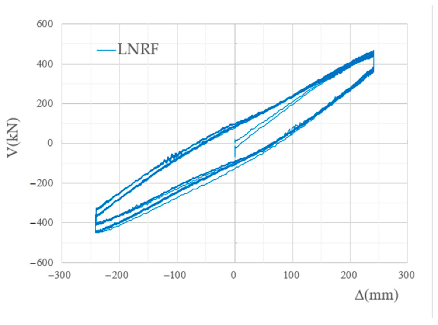
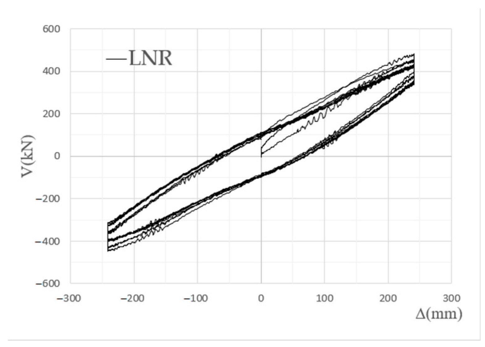
Figure 36 shows the hysteresis curves of the two bearings when subjected to compressive stress of 10 MPa and loaded to shear angles of 100%, 200%, 250% and 300%. The damping ratio is calculated based on the energy consumption area in the figure and Table 1, and the switching points of the two-stage damping devices are also marked with letters for the discussion below.
As can be seen from Figure 36, at the displacement of γ = 100%, the shapes of the LNR and LNRF hysteresis curves are similar; at displacement amplitudes of γ = 200% and above, the shapes of the two types of bearings’ hysteresis curves undergo significant changes: the latter provides greater resistance during loading and unloading, as well as reverse loading stages, causing the shape of the hysteresis curve to be bone-shaped. The loading stiffness of the latter is greater than that of the former, while the reverse loading stiffness is lower than that of the former. These characteristics make LNRF more conducive to the isolation and energy dissipation functions.
The data calculations for the influence of shear angle on the equivalent stiffness and damping ratio are shown in Figure 37 and Figure 38 respectively. Corresponding to the shear angles of 100%, 200%, 250% and 300%, the LNRF’s equivalent stiffness, calculated with the peak force and displacement values, is 21%, 22%, 22%, and 11% higher than that of LNR, respectively. The equivalent damping ratio in Figure 38 (for calculation, see Table 1) shows that LNRF keeps a gradually increasing trend from lower than LNR to higher than LNR, while the latter is gradually decreasing. When the shear displacement angle is 100%, the damping ratio of LNRF is relatively small, which is due to the lower slice strength and higher stiffness discussed above, which will be conducive to the isolation effect; however, when the shear displacement angle is greater than 175%, the damping ratio of LNRF is higher than that of LNR, which is beneficial for suppressing the displacement during rare earthquakes.
4.
The fatigue test
The fatigue tests on the bearings under horizontal loading are conducted with a shear angle of γ = 100%, loading frequencies of 0.02 and 0.03 Hz, and 30 loading circles. No low-cycle fatigue life test is performed because of the other needed ongoing tests. Figure 39 and Figure 40 show the force–displacement hysteresis curves of the specimens LNRF and LNR respectively. The results indicate that the maximum deviation of the peak friction force of the hysteresis curve is lower than the 15% requirement stipulated in the product standard, and the loading frequency has a certain influence on the results.
5.
The switching of friction dampers
The letters marked on the curve in Figure 36b reflect the switching process of the damper during the test. It can be briefly described in the following way: The forward loading begins at point b. The tapered rod of the first stage is gradually pulled out and supplies small friction force and shear force due to the place near the initial position. When it approaches point c while the angle reaches or exceeds 100%, the friction and shear force also gradually increase. When approaching point d, the friction of the first damper exceeds the second damper’s capacity and the latter is pulled out, where there is a slight curve fluctuation near point d, and then starting the 2nd sliding and completing a switch, and the second one provides the friction instead. When the second stage is fully extended, the maximum restoring force is reached at the maximum displacement. During unloading, the elastic deformation of the rod is restored first, and the second damper slides, and then its stable friction output exerts a resistance effect, showing that the curve tangent slope near point e is significantly greater than that of the LNR curve. When the reverse loading reaches point f, the curve around has obvious fluctuations caused by the retraction of the second friction damper and pushing the first stage into the reverse action. When it reaches point g, the damper and rubber bearing return to the original place. In reverse loading to opposite half-circle, starting from (b), it goes through (c)~(f) and then (g), and the switching process is similar to the forward loading.
6.
Characteristics of shear damping force of isolation bearings
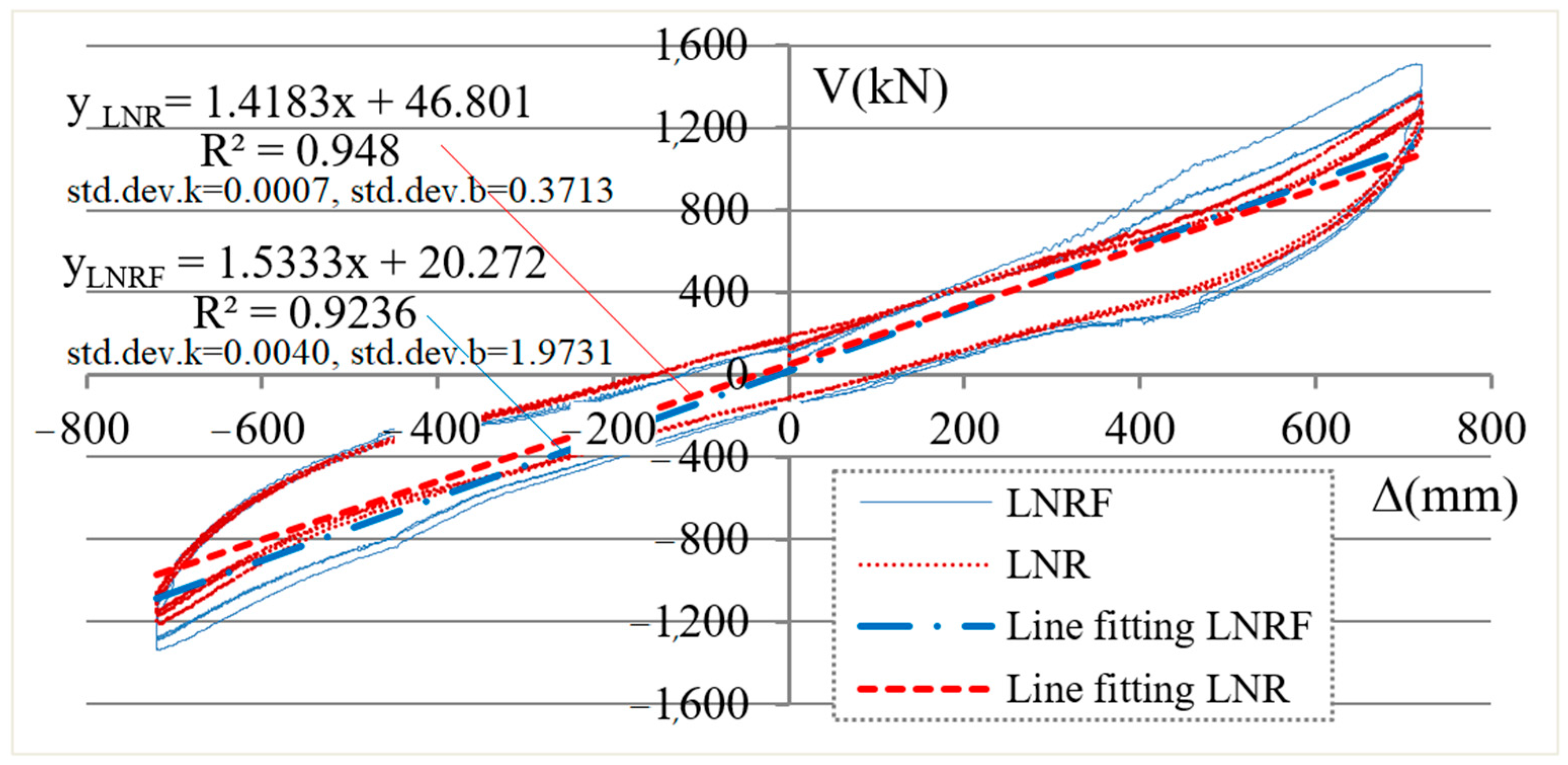
For the consideration of modeling, the hysteretic curve of the isolation bearing may be divided into elastic and energy dissipation parts, that is, the shear resistance Vt = elastic restoring force Ve + hysteretic damping shear force Vh. Here the shear displacement angle γ = 300% hysteresis curve shown in Figure 41 is taken as an example to illustrate the specific method:
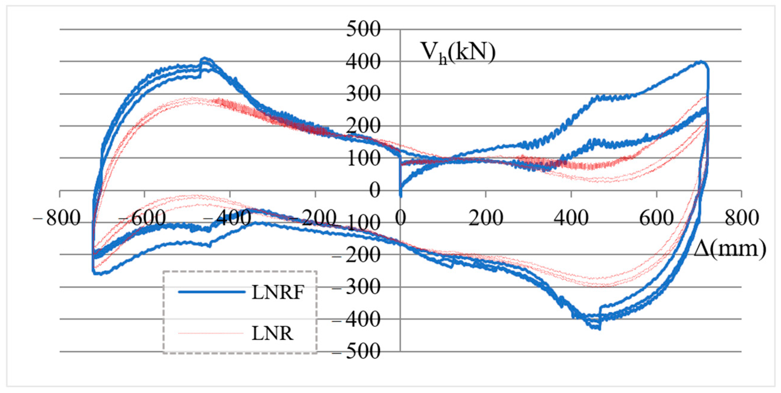
First, linear elastic fitting was performed on the hysteresis curve (the figures are annotated with the fitting equation, the determination coefficient, the standard deviation of the slope, and intercept parameters), which was taken as the elastic (shear) restoring force Ve. Then elastic restoring force Ve was subtracted from the corresponding force values Vt on the hysteresis curve to obtain the shear damping force Vh, as shown in Figure 42.
Because of the different structure of the two kinds of bearings, the shear damping force Vh of each kind comes from different components. The shear damping force of LNR comes from the laminated rubber and its adhesion with steel layers, namely Vh,LNR = Vr, while the shear damping force of LNRF bearing comes from both the laminated rubber plus the adhesion and the added friction damper, namely Vh,LNRF = Vr + Vf. Therefore, by deducting the damping force Vr provided by the laminated rubber bearing of the same specifications from the total shear damping force of LNRF, the shear damping force provided by the friction dampers connected according to Figure 2 can be approximated, i.e., Vf = Vh,LNRFVr.
As can be seen from Vh, in Figure 42, several characteristics of the isolation bearing are as follows:
Firstly, the hysteresis damping force Vh of LNRF is greater than that of LNR. The additional part of the former is provided by the friction dampers. The contribution of the shear damping force Vf of LNRF to the total shear resistance increases with the increase in the shear angle of the bearing during the sliding of the first-stage damper, which is mainly affected by the shear angle and the increase in the friction force of the tapered rod; during the sliding of the second stage, it gradually decreases as the shear angle of the bearing increases, which is probably influenced by the gradually decreasing sliding velocity of the friction tiles. Therefore, in general, the friction shear damping force Vf of the combined isolation bearing is a variable damping force.
Secondly, at small displacements, the total damping force Vh,LNRF of LNRF, which is Vr + Vf, is approximately the same as that of LNR, which is Vr. However, at large displacements, its damping force is significantly greater than the latter, and the energy dissipation area is also significantly larger. When reverse loading is applied at the large displacement end, due to the friction tiles undergoing a process from static to dynamic, large damping forces can also be obtained in the second and fourth quadrants of the hysteresis curve. The increased damping force of the damper at the large displacement end makes the characteristic of the bone-shaped hysteresis curve obvious.
Third, it is worth noting that the shear damping force of LNRF is different from the hysteresis curve provided by the lead core of a conventional lead–rubber bearing, which remains almost the same under small and large displacements [36].
The above characteristics show that LNRF provides a relatively small damping force at small displacement and a larger damping force under large displacement in a variable damping way, which is different from conventional isolation bearings (including lead–rubber bearings). According to isolation design theory [36], it can be predicted that not only the design of LNRF reduce the seismic response and improve the comfort of a building under frequent earthquakes, but also, by reducing the displacement of isolation layer under rare earthquakes, the width of isolation trench and the adaptive width of other facilities passing through the trench can be reduced. Therefore, there are obvious benefits in practical engineering.
7.
Mechanical parameters of hysteresis curve and equivalent viscous damping ratio
Table 1 summarizes the mechanical parameters of the two kinds of tested bearings, including equivalent stiffness, shear capacity, slice strength, and equivalent viscous damping ratio (see also Figure 35 and Figure 36). This can be used as a reference for further modeling. The equivalent viscous damping ratio of LNRF is increased by −14.8%, 7.1%, 20.2%, and 24% compared with LNR respectively (note that the damping ratio is a negative increment at the 100% shear angle, which does not mean that the energy dissipation has decreased. This is because the stiffness has increased by 22.4%, and the dissipated energy has increased by 4.5%, overall resulting in a 14.8% reduction in the damping ratio). This indicates that the combined seismic isolation bearing has a higher equivalent viscous damping ratio in the range of shear angle more than 100%, and the value maintains a relatively stable output.

5. Conclusions

In this paper, a novel combined seismic isolation bearing with two-stage friction dampers is proposed and developed. Tests are carried out on the friction dampers of each stage and the combined isolation bearings. The structural design theory of dampers, mechanical properties, and seismic performance of both friction dampers and isolation bearings, the differences between the two isolation bearings are studied. The assembly and testing of the dampers, as well as the testing of the combined bearing, have achieved the expected goals. The main conclusions are as follows:
(1)
The sliding rod in the first stage damper is gently tapered cylinder, and the sliding rod in the second one is a cylindrical rod (constant section). The semi-metal friction tiles are compressed by pre-tightened retaining hoop to obtain the required friction capacity. The relayed damper containing the two stages increases the slide range significantly compared with the previous friction damper, and can adapt to the large horizontal displacement requirements of seismic isolated rubber bearing.
(2)
The characteristics of the force–displacement hysteresis curve of the friction dampers are confirmed, where the 1st stage damper has a trumpet-like curve and the second one is like rectangular, through the individual tests. Technical parameters under the variable amplitude and velocity loading are determined. The combined values of pre-tightened torque suit for the two kinds of friction tiles are provided for the realization of the relay operation. Select a semi-metal friction tile to reduce vibration noise.
(3)
A design method for friction dampers has been established through internal forces and deformation analysis based on the theory of elasticity. The construction dimensions, material properties, mechanical parameters, as well as the relationship between output force and displacement are clearly defined. Calculation formulas for the bearing capacity, displacement, and cross-sectional dimensions of the friction dampers are provided. The maximum force value, stiffness, damping ratio, and the number of combinations of the dampers can be adjusted to achieve a compact design, improving the design efficiency. This helps the structural design of combined isolation bearings and the development of various specification products.
(4)
The combined isolation bearings’ test results demonstrated the effective operation and switching of the two-stage friction dampers, enabling the generation of large shear force output at the large shear displacement end (positive and reverse loading points), achieving a stable output of the bone-shaped horizontal force–displacement hysteresis curve with a variable damping effect. The compression–shear tests of the 1300 mm diameter full-scale laminated rubber bearing (LNR) and the combined isolation bearing (LNRF), at a vertical compressive stress of 10 MPa, showed that, corresponding to a shear angle of 100%, the equivalent viscous damping ratio of LNRF was 14.8% lower than that of LNR (due to the increase in stiffness). Corresponding to shear angles of 200%, 250%, and 300%, the equivalent damping ratios could increase by 7.1%, 20.2%, and 24.0% respectively. The fatigue tests of the dampers and the combined isolation bearings both met or exceeded the requirements of relevant technical standards [18,19].
(5)
Based on the test results presented in this article, the analysis of the differences in shear damping forces of these two types of bearings indicates that LNRF can provide variable damping forces, and the hysteresis curve shows a distinct bone-like shape, which is different from traditional isolation bearings (including lead–rubber bearings). The design of these isolation bearings can enhance the comfort of buildings during frequent earthquakes, and, by reducing the displacement during rare earthquakes to decrease the width of the isolation trench, it will have significant benefits in practical engineering.

Author Contributions

Conceptualization, X.G. and J.S.; methodology, X.G.; software, X.G., J.Z., W.H. and F.W.; data curation, J.W., F.W. and J.Z.; writing—original draft preparation, X.G., C.W. and F.W.; writing—review and editing, X.G., J.S. and Q.G.; design, X.G., J.S., J.W., C.W., J.Z. and W.H.; tests, J.W., C.W., W.H., F.W., X.G. and J.S.; visualization, X.G., J.W. and C.W.; project administration, Q.G. and J.S.; funding acquisition, Q.G. All authors have read and agreed to the published version of the manuscript.

Funding

This research was funded by: 1. Yunnan Provincial Talent Development and Technology Platform Construction Project (Grant No.202405AD350094, 202505AK340007); 2. Quakesafe Technologies Co., LTD., and Beijing University of Technology, “R&D project of the combined isolation bearings (LNRF) 2022–2024”, grant number “QST-2022-002”.

Data Availability Statement

The original contributions presented in this study are included in the article. Further inquiries on the data can be directed to the corresponding author.

Acknowledgments

The authors sincerely thank the technicians who contributed to the completion of the tests of the friction dampers and the combined isolation bearings. At the same time, we also express our gratitude to Quicksafe Technology Co., Ltd. and Beijing University of Technology, as well as Yunnan Province for providing the funds and equipment support for this project. It was precisely this support that enabled the successful production of the test samples and the completion of all the tests.

Conflicts of Interest

Authors Qingsong Guan, Jiuwei Wang and Chengwei Wang were employed by the company Quakesafe Technologies Co., Ltd. Kun. The remaining authors declare that the research was conducted in the absence of any commercial or financial relationships that could be construed as a potential conflict of interest.

References

  1. De Domenico, D.; Gandelli, E.; Quaglini, V. Effective base isolation combining low-friction curved surface sliders and hysteretic gap dampers. Soil Dyn. Earthq. Eng. 2020, 130, 105989. [Google Scholar] [CrossRef]
  2. Sharma, A.; Jangid, R.S. Influence of high initial isolator stiffness on the seismic response of a base-isolated benchmark building. Int. J. Struct. Stab. Dyn. 2011, 11, 1201–1228. [Google Scholar] [CrossRef]
  3. Providakis, C.P. Effect of LRB isolators and supplemental viscous dampers on seismic isolated buildings under near-fault excitations. Eng. Struct. 2008, 30, 1187–1198. [Google Scholar] [CrossRef]
  4. Hwang, J.S.; Hung, C.F.; Huang, Y.N.; Wang, S.J. Design force transmitted by isolation system composed of lead-rubber bearings and viscous damper. Int. J. Struct. Stab. Dyn. 2010, 10, 287–298. [Google Scholar] [CrossRef]
  5. Lu, L.-Y.; Lin, G.-L. Improvement of near-fault seismic isolation using a resettable variable stiffness damper. Eng. Struct. 2009, 31, 2097–2114. [Google Scholar] [CrossRef]
  6. Nguyena, X.D.; Guizani, L. Analytical and numerical investigation of natural rubber bearings incorporating U-shaped dampers behavior for seismic isolation. Eng. Struct. 2021, 243, 112647. [Google Scholar]
  7. Qiu, C.; Tian, L. Feasibility analysis of SMA-based damping devices for use in seismic isolation of low-rise frame buildings. Int. J. Struct. Stab. Dyn. 2018, 18, 1850087. [Google Scholar]
  8. Wang, B.; Zhang, Z.; Chen, P.; Zhu, S.; Dai, K. Self-centering capability of seismically isolated structures after earthquakes. Adv. Eng. Sci. 2023, 55, 5–13, (In Chinese with English Abstract). [Google Scholar]
  9. Li, X.; Wang, W. Study on numerical simulation of uplift resistance triple friction pendulum isolation bearing. Earthq. Resist. Eng. Retrofit. 2016, 38, 85–88, (In Chinese with English Abstract). [Google Scholar]
  10. Liu, W.; Sun, X.; He, W.; Zhang, Q.; Zi, D. Experimental study and dynamic response analysis of rotational three-dimensional seismic isolation system. J. Build. Struct. 2021, 42, 47–55, (In Chinese with English Abstract). [Google Scholar]
  11. He, W.; Qiao, J.; Xu, H.; Huang, J. Experiment investigation and dynamic responses of three-dimensional isolation system with high-static-low-dynamic stiffness. Soil Dyn. Earthq. Eng. 2023, 165, 107679. [Google Scholar]
  12. Koo, G.-H.; Jung, J.-Y.; Hwang, J.-K.; Shin, T.-M.; Lee, M.-S. Vertical Seismic Isolation Device for Three-Dimensional Seismic Isolation of Nuclear Power Plant Equipment—Case Study. Appl. Sci. 2022, 12, 320. [Google Scholar] [CrossRef]
  13. Ruano, P.C.; Strauss, A. Finite Element Analysis for Nonlinear Unbonded Circular Fiber-Reinforced Elastomeric Bearings. J. Compos. Sci. 2021, 5, 170. [Google Scholar] [CrossRef]
  14. Tian, J.; Jiao, D.; Sun, T.; Fang, G.; Peng, L. Experimental study on isolation bearing with constant damping and tensile function. Earthq. Resist. Eng. Retrofit. 2019, 41, 120–125, (In Chinese with English Abstract). [Google Scholar] [CrossRef]
  15. Mirtaheri, M.; Zandi, A.P.; Samadi, S.S.; Samani, H.R. Numerical and experimental study of hysteretic behavior of cylindrical friction dampers. Eng. Struct. 2011, 33, 3647–3656. [Google Scholar] [CrossRef]
  16. Han, W.; Gao, X.; Wu, F.; Tian, J.; Wang, Z. Design and performance study of a novel isolation bearing. China Earthq. Eng. J. 2024, 46, 144–155, (In Chinese with English Abstract). [Google Scholar] [CrossRef]
  17. Zhou, J.; Gao, X.; Xiao, Y.; Su, J.; Chen, J.; Yang, J. Feasibility study of isolation optimization scheme for a nuclear island plant with new combined isolation bearings. Build. Struct. 2025, 55, 44–51, (In Chinese with English Abstract). [Google Scholar] [CrossRef]
  18. GB/T 51408-2021; Standard for Seismic Isolation Design of Building. Ministry of Housing and Urban Rural Development of the People’s Republic of China: Beijing, China, 2021. (In Chinese)
  19. JGJ 297-2013; Technical Specification for Seismic Energy Dissipation of Buildings. Ministry of Housing and Urban Rural Development of the People’s Republic of China: Beijing, China, 2013. (In Chinese)
  20. Blau, P.J. Compositions, Functions, and Testing of Friction Brake Materials and Their Additives; OAK RIDGE National Laboratory, Department of Energy: Oak Ridge, TN, USA, 2001.
  21. Darius, G.S.; Berhan, M.N.; David, N.V.; Shahrul, A.A.; Zaki, M.B. Characterization of brake pad friction materials. In Computational Methods and Experiments in Material Characterization II, WIT Transactions on Engineering Sciences; WIT Press: Southampton, UK, 2005; Volume 51, ISSN 1743-3533. [Google Scholar]
  22. Kondoh, K. Powder Metallurgy; InTech: Rijeka, Croatia, 2012; ISBN 978-953-51-0071-3. [Google Scholar]
  23. Basso, D. Dynamic Characterization of Brake Pads Friction Material in Typical Squeal Frequency Range. Master’s Thesis, Facoltà di Ingegneria Industriale, Politecnico di Milano, Milano, Italy, 2015. [Google Scholar]
  24. Kim, N. Ultrasonic Evaluation of Young’s Modulus for Reduction of Brake Squeal Noise. IOP Conf. Ser. Mater. Sci. Eng. 2019, 542, 012073. [Google Scholar] [CrossRef]
  25. Serrano-Munoz, I.; Magnier, V.; Brunel, F.; Dufrenoy, P. Influence of the Composition on the Compressive Behaviour of a Semi-Metallic Brake-Pad, Material. Materials 2022, 15, 7911. [Google Scholar] [PubMed]
  26. Mege-Revil, A.; Rapontchombo-Omanda, J.; Serrano-Munoz, I.; Cristol, A.-L.; Magnier, V.; Dufrenoy, P. Sintered Brake Pads Failure in High-Energy Dissipation Braking Tests: A Post-Mortem Mechanical and Microstructural Analysis. Materials 2023, 16, 7006. [Google Scholar] [PubMed]
  27. Chaurasiya, A.K.; Ramakumar, P.; Balasubramanian, M. Effect of aluminum/copper as a metal filler in non-asbestos organic (NAO) brake composites materials for medium duty application. J. Tribol. 2023, 37, 113–127. [Google Scholar]
  28. Su, D.; Li, D.; Wang, L.; Wang, P. Friction and Wear Behavior of Two Semi-metallic Friction Materials. Tribology 2000, 20, 383–385. [Google Scholar]
  29. Mao, M. Modeling and Experimental Study of the Friction Behaviors in Micro-Forming of Sheet Metal. Ph.D. Thesis, School of Mechanical Engineering, Shanghai Jiao Tong University, Shanghai, China, 2018. [Google Scholar]
  30. Zhong, Z.; Xu, C.; Wang, L.; Hua, Y.; Zhang, F. Experimental investigation on frictional properties of stressed basalt. J. Rock Mech. Geotech. Eng. 2023, 15, 1457–1475. [Google Scholar] [CrossRef]
  31. GB/T 34422-2017; Brake Disc for Automobile. General Administration of Quality Supervision, Inspection and Quarantine of China: Beijing, China; Standardization Administration of China: Beijing, China, 2018.
  32. J840_201711; Test Procedures for Shear Strength of Automotive Brake Pads and Brake Lining Assemblies. Society of Automotive Engineering International: Warrendale, PA, USA, 2017.
  33. Xu, Z. Mechanics of Elasticity-the Third Concise Edition. In General Higher Education “Tenth Five-Year” National Planning Textbooks; Higher Education Press: Beijing, China, 2001; ISBN 978-7-04-010719-7. [Google Scholar]
  34. Olsson, H.; Åström, K.J.; de Wit, C.C.; Gäfvert, M.; Lischinsky, P. Friction Models and Friction Compensation. Eur. J. Control 1998, 4, 176–195. [Google Scholar] [CrossRef]
  35. Khalil, H.K. Nonlinear Systems, 3rd ed.; Zhu, S.; Dong, H.; Li, Z., Translators; Publishing House of Electronics Industry: Beijing, China, 2005; ISBN 7-121-01142-5. [Google Scholar]
  36. Skinner, R.A.; Robinson, W.H.; McVerry, G.H. An Introduction to Seismic Isolation; John Wiley and Sons Ltd.: Hoboken, NJ, USA, 1993; ISBN 10:047193433X, 13:9780471934332. [Google Scholar]
Figure 1. Two-stage friction damper. 1—outer cylinder; 2—middle cylinder; 3—baffle plate; 4—stage retaining hoop; 5—outer upper cover; 6—first-stage retaining hoop; 7—guide tube; 8—inner cylinder (gently tapered tube); 9—first-stage friction tiles; 10—stage friction tiles; 11—guide block; 12—middle lower-cover.
Jcs 10 00354 g001
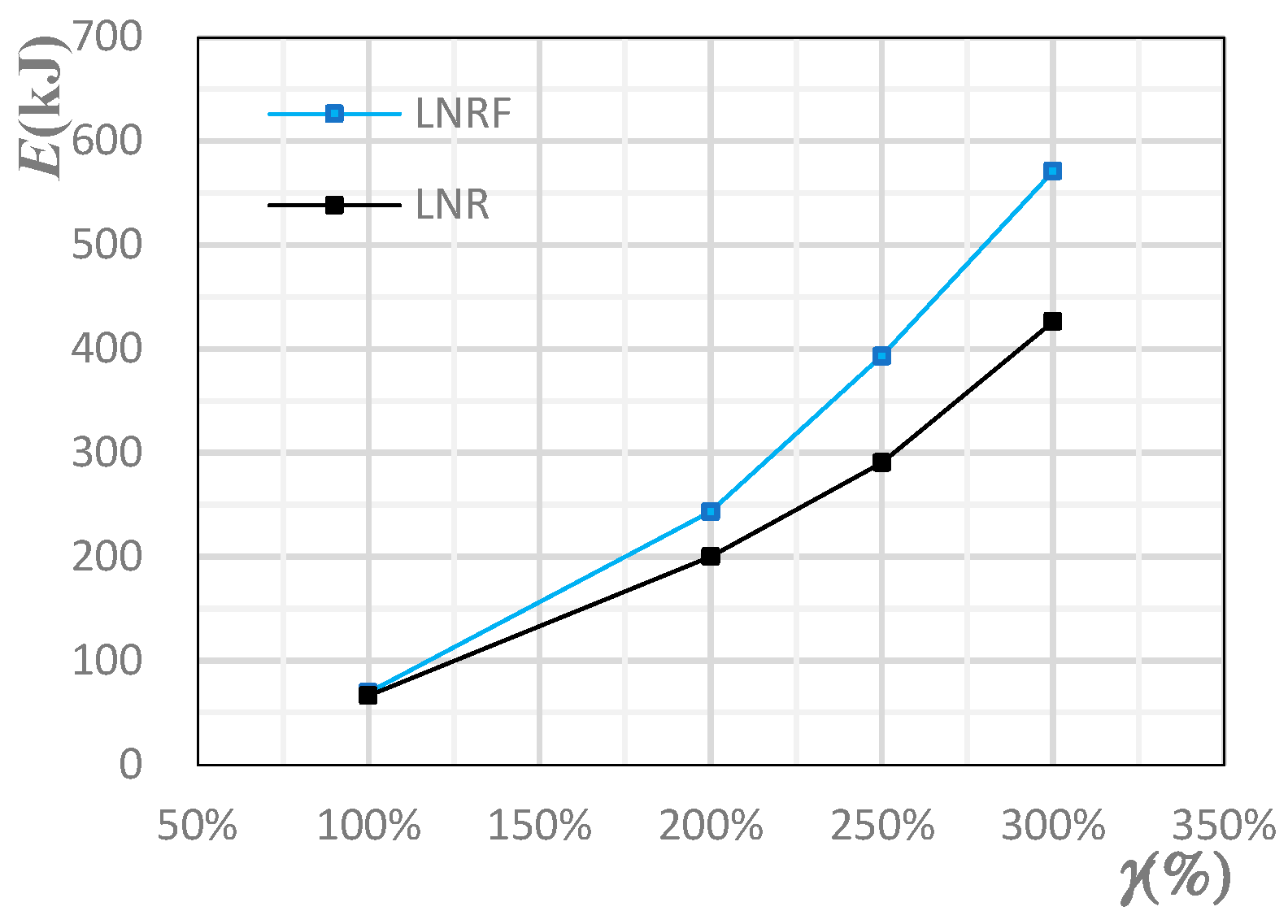
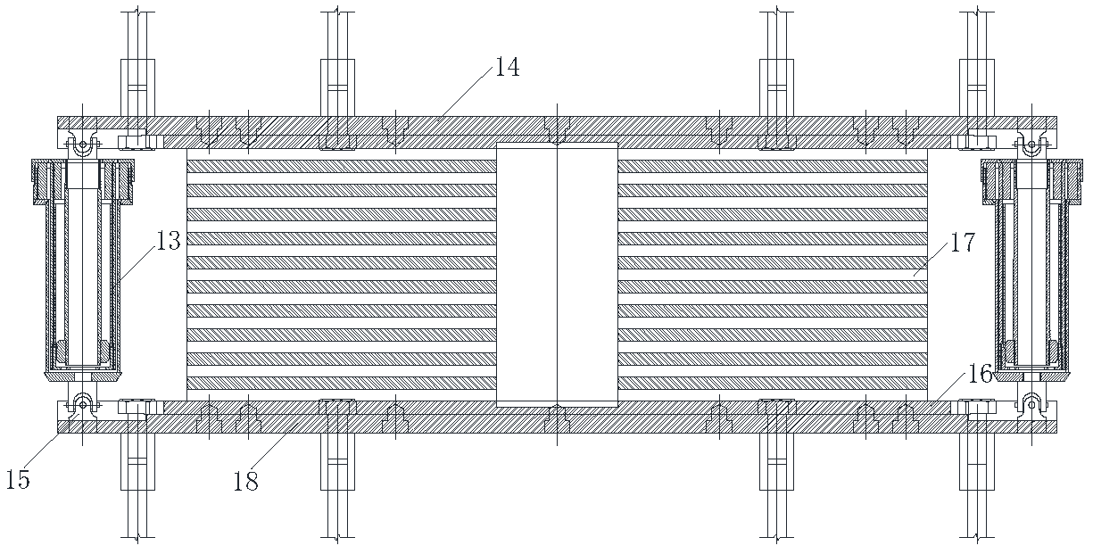
Figure 2. Combined isolation bearing. 13—friction damper; 14—upper connection plate; 15—cross-hinge connector; 16—lower-end plate; 17—laminated rubber bearing (LNR); 18—lower connection plate.
Jcs 10 00354 g002
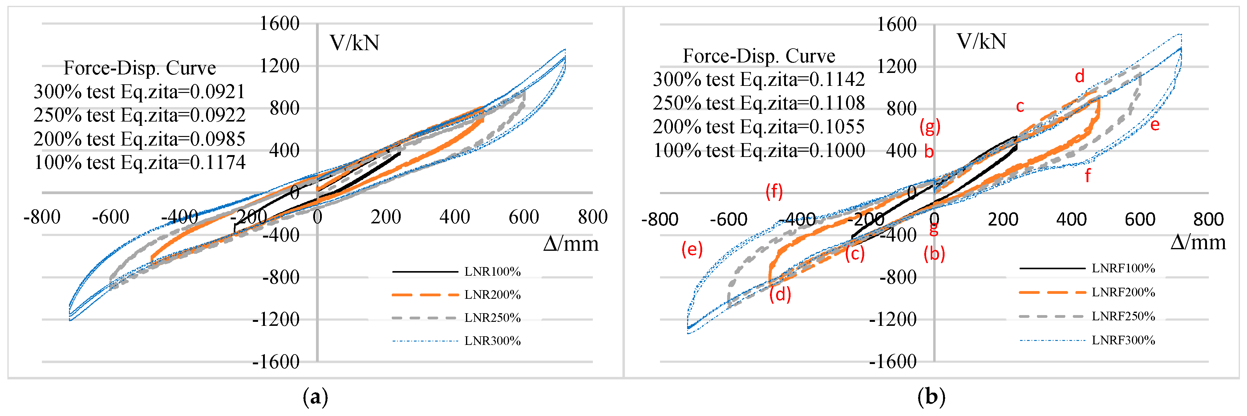
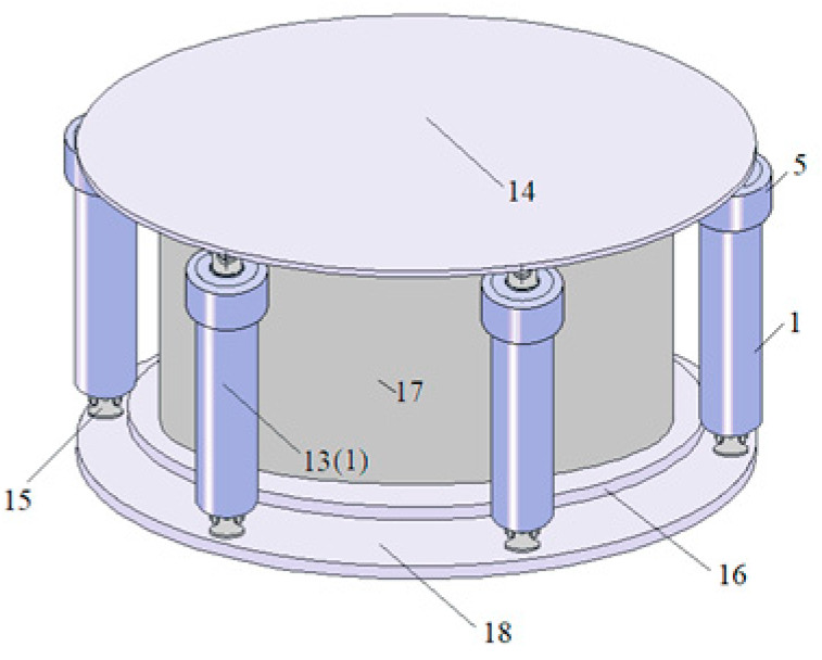
Figure 3. Oblique view of LNRF. 1—outer cylinder; 5—outer upper cover; 13—friction damper; 14—upper connection plate; 15—cross-hinge connector; 16—lower-end plate; 17—laminated rubber bearing (LNR); 18—lower connection plate.
Jcs 10 00354 g003
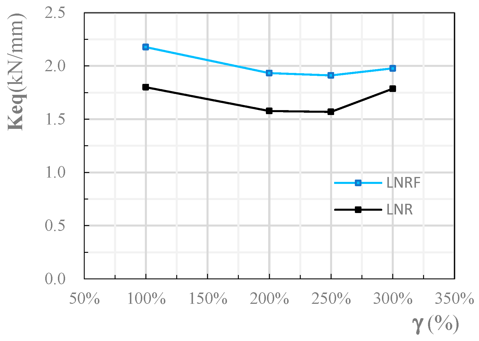
Figure 4. The separated friction damper tests and two in one assembly effect (see Figure 1 for the numbers). (a) The first-stage damper; (b) the second-stage damper; (c) two-in-one assembly effect.
Jcs 10 00354 g004
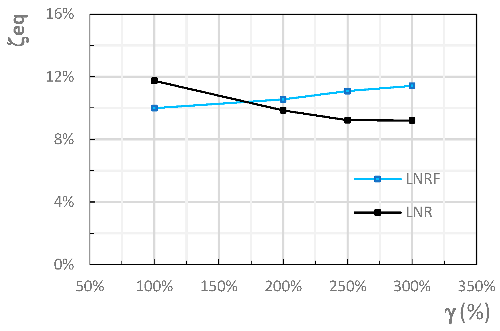
Figure 5. Semi-metal tile 1st damper pre-torque of 1.2 Nm. (a) (0.02 Hz, 20 mm). (b) (0.02 Hz, 60 mm).
Jcs 10 00354 g005
Figure 6. Semi-metal tile 1st damper pre-torque of 1.6 Nm. (a) (0.02 Hz, 20 mm). (b) (0.02 Hz, 60 mm).
Jcs 10 00354 g006
Figure 7. Full-metal tile 1st damper pre-torque of 1.2 Nm. (a) (0.02 Hz, 20 mm). (b) (0.02 Hz, 60 mm).
Jcs 10 00354 g007
Figure 8. Full-metal tile 1st damper pre-torque of 1.6 Nm. (a) (0.02 Hz, 20 mm). (b) (0.02 Hz, 60 mm).
Jcs 10 00354 g008
Figure 9. Semi-metal tile 2nd damper pre-torque of 20 Nm. (a) (0.02 Hz, 20 mm). (b) (0.02 Hz, 60 mm).
Jcs 10 00354 g009
Figure 10. Semi-metal tile 2nd damper pre-torque of 24 Nm. (a) (0.02 Hz, 20 mm). (b) (0.02 Hz, 60 mm).
Jcs 10 00354 g010
Figure 11. Full-metal tile 2nd damper pre-torque of 20 Nm. (a) (0.02 Hz, 20 mm). (b) (0.02 Hz, 60 mm).
Jcs 10 00354 g011
Figure 12. Full-metal tile 2nd damper pre-torque of 24 Nm. (a) (0.02 Hz, 20 mm). (b) (0.02 Hz, 60 mm).
Jcs 10 00354 g012
Figure 13. Semi-metal 1st damper in different freq. load. (a) (50 mm, 0.05 Hz). (b) (50 mm, 0.3 Hz).
Jcs 10 00354 g013
Figure 14. Full-metal 1st damper in different freq. load. (a) (50 mm, 0.05 Hz). (b) (50 mm, 0.3 Hz).
Jcs 10 00354 g014
Figure 15. Semi-metal 2nd damper in different freq. load. (a) (50 mm, 0.05 Hz). (b) (50 mm, 0.3 Hz).
Jcs 10 00354 g015
Figure 16. Full-metal 2nd damper in different freq. load. (a) (50 mm, 0.05 Hz). (b) (50 mm, 0.3 Hz).
Jcs 10 00354 g016
Figure 17. Amplitude influence on the 1st damper.
Jcs 10 00354 g017
Figure 18. Amplitude influence on the 2nd damper.
Jcs 10 00354 g018
Figure 19. Frequency influence on the 1st damper.
Jcs 10 00354 g019
Figure 20. Frequency influence on the 2nd damper.
Jcs 10 00354 g020
Figure 21. Wear phenomenon of the semi-metal tiles (left) and full-metal tiles (right).
Jcs 10 00354 g021
Figure 22. Construction and force state decomposition of the 1st-stage friction damper.
Jcs 10 00354 g022
Figure 23. Vt = Vf + Vr.
Jcs 10 00354 g023
Figure 24. Influence of x/h (assume Ti = const.).
Jcs 10 00354 g024
Figure 25. Influence of loading velocity S ˙ .
Jcs 10 00354 g025
Figure 26. Loading velocity and displacement.
Jcs 10 00354 g026
Figure 27. The compressive shear testing machine.
Jcs 10 00354 g027
Figure 28. LNRF testing (front view).
Jcs 10 00354 g028
Figure 29. LNRF testing (back view).
Jcs 10 00354 g029
Figure 30. Vertical compressive test hysteresis curves.
Jcs 10 00354 g030
Figure 31. Effect of σv on vertical stiffness.
Jcs 10 00354 g031
Figure 32. The correlation between Δv and Δh.
Jcs 10 00354 g032
Figure 33. Influence of σv on the hysteretic curves of two kinds bearings (σv = 5 and 15 MPa). (a) LNR V-Δ curves with σv = 5, 15 MPa. (b) LNRF V-Δ curves with σv = 5, 15 MPa.
Jcs 10 00354 g033
Figure 34. Influence of σv on energy dissipation (γ = 200%).
Jcs 10 00354 g034
Figure 35. Influence of γ on energy dissipation (σv = 10 MPa).
Jcs 10 00354 g035
Figure 36. Shear displacement hysteresis curves of the two kinds seismic isolation bearings (σv = 10 MPa). (a) LNR V-Δ curves with σv = 10 MPa. (b) LNRF V-Δ curves with σv = 10 MPa.
Jcs 10 00354 g036
Figure 37. Influence of γ on loading equivalent stiffness.
Jcs 10 00354 g037
Figure 38. Influence of γ on equivalent damping ratio.
Jcs 10 00354 g038
Figure 39. Fatigue test curves of LNRF.
Jcs 10 00354 g039
Figure 40. Fatigue test curves of LNR.
Jcs 10 00354 g040
Figure 41. Hysteresis curve and the elastic linear fitting.
Jcs 10 00354 g041
Figure 42. Shear damping force Vh curve of the two bearings.
Jcs 10 00354 g042
Table 1. Basic mechanical properties of tested LNRF and LNR.
Performance IndexLNRF Shear Angle LevelLNR Shear Angle Level
100%200%250%300%100%200%250%300%
Mechanical PropertiesShear disp. amplitude Δm(mm)240480600720239478600720
Equivalent stiffness Keq (kN/mm)2.181.931.911.981.81.581.561.79
Fitted stiffness Kfit (kN/mm)1.911.591.571.531.561.41.341.42
Shear capacity Vsc (kN)523928114714244337579421286
Slicing force V0 (kN)8711711615093122137150
Dissipated energy Wd (kJ)69.358243.28393.133571.2266.386200.005290.538426.162
Equivalent viscos. damping ratio ζeq10.00%10.55%11.08%11.42%11.74%9.85%9.22%9.21%
ζeq,LNRFeq,LNR0.8521.0711.2021.2401.0001.0001.0001.000
Note: the data is based on the average peak value of forward and reverse load and shear displacement. The equivalent damping ratio is calculated via the formula ζeq = Wd/(4πWs), where Ws is calculated via fitted stiffness (Kfit, see Figure 41) for the amplitude.
Disclaimer/Publisher’s Note: The statements, opinions and data contained in all publications are solely those of the individual author(s) and contributor(s) and not of MDPI and/or the editor(s). MDPI and/or the editor(s) disclaim responsibility for any injury to people or property resulting from any ideas, methods, instructions or products referred to in the content.