1. Introduction
Contemporary automotive interior design is undergoing a paradigm shift from functionalism to experiential aesthetics, where the integration of lightweight engineering and biomimetic design creates new possibilities for the dialogue between art and technology. From the perspective of art and design disciplines, the roof handrail is not only a functional component but also an important carrier for the emotional and aesthetic transformation of the driving and riding space.
In this technological context, additive manufacturing technology has reconstructed the manufacturing paradigm with its disruptive production methods. By eliminating the physical limitations of traditional molds [
1], the creative potential of complex geometric shapes has been unleashed, providing designers with unprecedented degrees of freedom in form. Scholars such as Yang [
2] and Li [
3] have promoted the process of lightweighting through material innovation, while Wellendorf [
4] and Wang [
5] have broken through traditional design boundaries through static simulation and additive manufacturing technology. These technological innovations provide a path for artistic expression of automotive lightweighting [
6]. This digital layer-by-layer accumulation process not only improves material utilization to an almost ideal state [
7] but also achieves agile transformation from concept to product by shortening the production chain, injecting unprecedented economy and creativity into engineering design. The mechanical aesthetics demonstrated by the lightweight transmission design of the Kartanas L [
8], as well as the high-performance lithium batteries achieved by Liu [
9] through additive manufacturing, are all confirming János Plocher’s [
10] prediction that the manufacturing revolution is reshaping the DNA of industrial production. The use of topology methods in automotive structural optimization has also become a design trend. Jankovics [
11] uses topology optimization methods to optimize the design of car frames, making them more suitable for additive manufacturing methods. Yue [
12] used topological methods to optimize car seats for better shock absorption.
At the intersection of bionics and engineering design, spider web structures are reshaping lightweight design with their exquisite natural intelligence. Xu [
13] elaborated on the significance of bionics in automotive interior design and proposed an interior design inspired by sea taro. Zhuo [
14] revealed the excellent structural performance and adaptability of spider webs through observation and modeling, proving that spider webs can become objects of biomimetic engineering. The web dynamics model constructed by Zhao [
15] from a multidisciplinary perspective has decoded the beauty of the spider’s eight-legged collaborative weaving algorithm. This kind of structural intelligence, derived from billions of years of evolution, has blossomed in engineering practice—from Liu’s [
16] biomimetic modification of turbine blades to Zhang’s [
17] medical titanium mesh, from Chi G’s [
18] life-saving solution for the water collection device to optimal selection of reinforcement schemes for the reinforced concrete structure of old industrial plants by Wu [
19], the spider web structure continues to break through application boundaries. The extraordinary mechanical properties of spider silk revealed by Ko Frank K [
20] and the quantified energy dissipation mechanism by Safikhani Nasim, Mohsen [
21] provide molecular-level annotations for Katrin Greta Hoffmann’s [
22] “technology organic” aesthetics. When natural selection pressure meets human computational simulation, spider webs have transformed from hunting tools in the forest to topology optimization textbooks in the hands of engineers. Their structural language extends from microscopic fibers to macroscopic architecture, writing a design revolution across scales. The existing research on biomimetic lightweight structures and automotive interior components in additive manufacturing has made fruitful progress, but there is insufficient research on biomimetic lightweight design of automotive interior auxiliary functional components.
At present, research mainly focuses on the body frame, battery structure, seats, and other core load-bearing components. There is little research on small auxiliary internal components such as roof handrails. Most internal lightweight optimizations only pursue a single reduction in mass, without integrating biomimetic aesthetics, ergonomic elastic cushioning, and mechanical safety into a unified design framework. And current spider web biomimetic research focuses on the structural application in aerospace, medical treatment, architecture and other fields, and automobile research of additive manufacturing combined with biomimetic lattice structure also focuses on the single lightweight target of body and power components, but there are still areas not covered. In other words, there is less structural layout optimization for auxiliary parts inside the vehicle. This study takes the NIO U-shaped handrail as the carrier and transforms the growth algorithm of the Eight Trigrams spider web into a manufacturable subdivision surface through parametric modeling, making the radial mesh a physical channel for stress transmission and forming a biometric appearance. The strength and deformation distribution characteristics of the structure at different scales are analyzed through the layered simulation of micro-elements and planar modules. Compare the X/Y/Z multi-axis layout and complete the structure selection optimization. By comparing the suitability between the two additional materials and bionomics structure, the material selection basis is given in combination with the safety factor. The spider web biomimetic handrail made of PA6-CF material not only meets safety regulations in terms of strength but also has a certain degree of elastic deformation ability, which can provide effective cushioning effect and create a better user experience. This study explores the balance between material properties and design freedom under the empowerment of additive manufacturing technology by constructing a three-dimensional parametric model, finite element simulation optimization, and material performance comparison. Through simulation, sample printing and indoor static tensile test, the data interactive verification is finally realized. The aim is to create automotive interior components that combine lightweight functionality, mechanical reliability, and artistic aesthetic value, providing practical samples for cross-border innovation in automotive design.
3. Simulation Paradigms
3.1. Simulation Analysis of Different Structural Units and Planar Systems
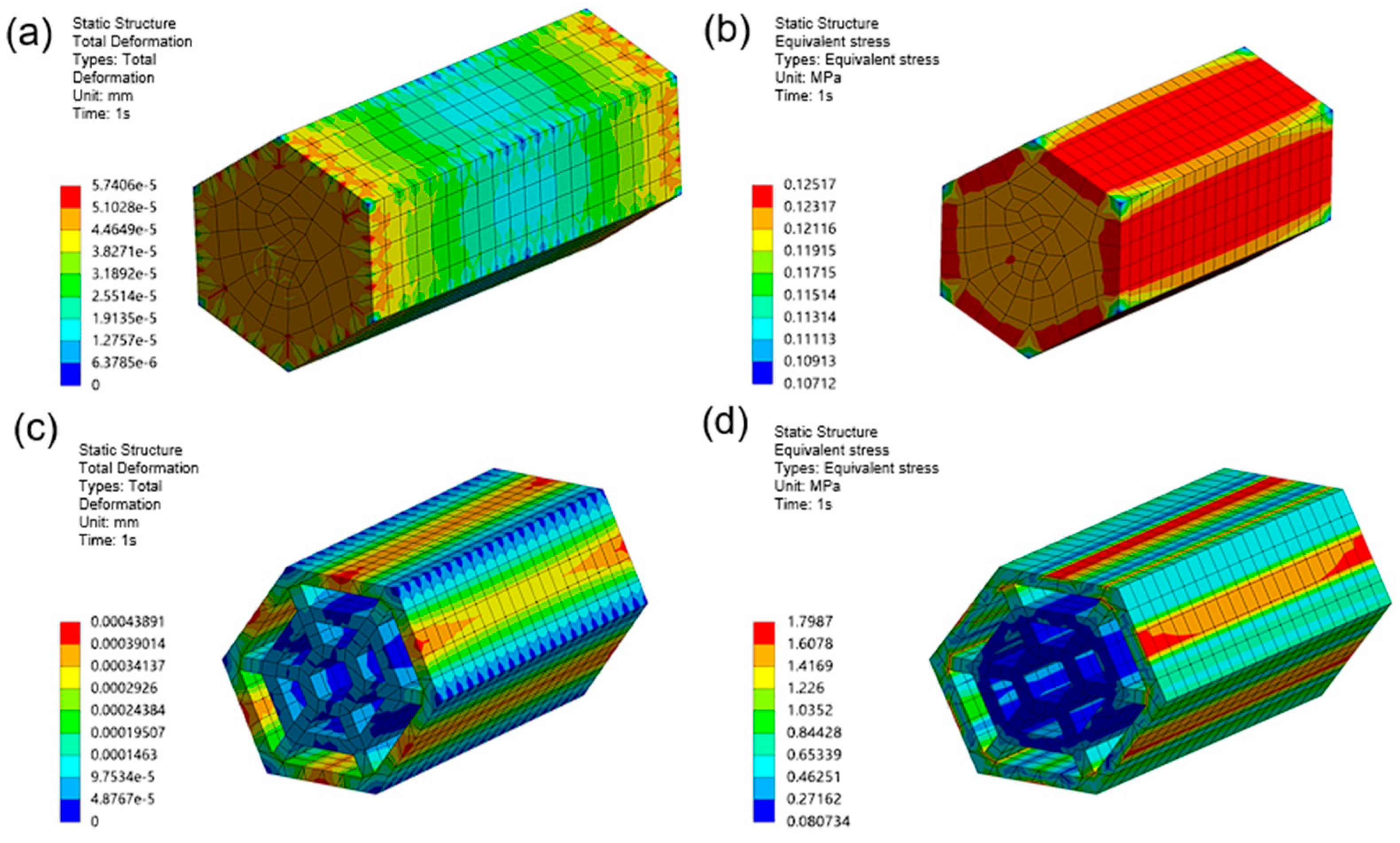
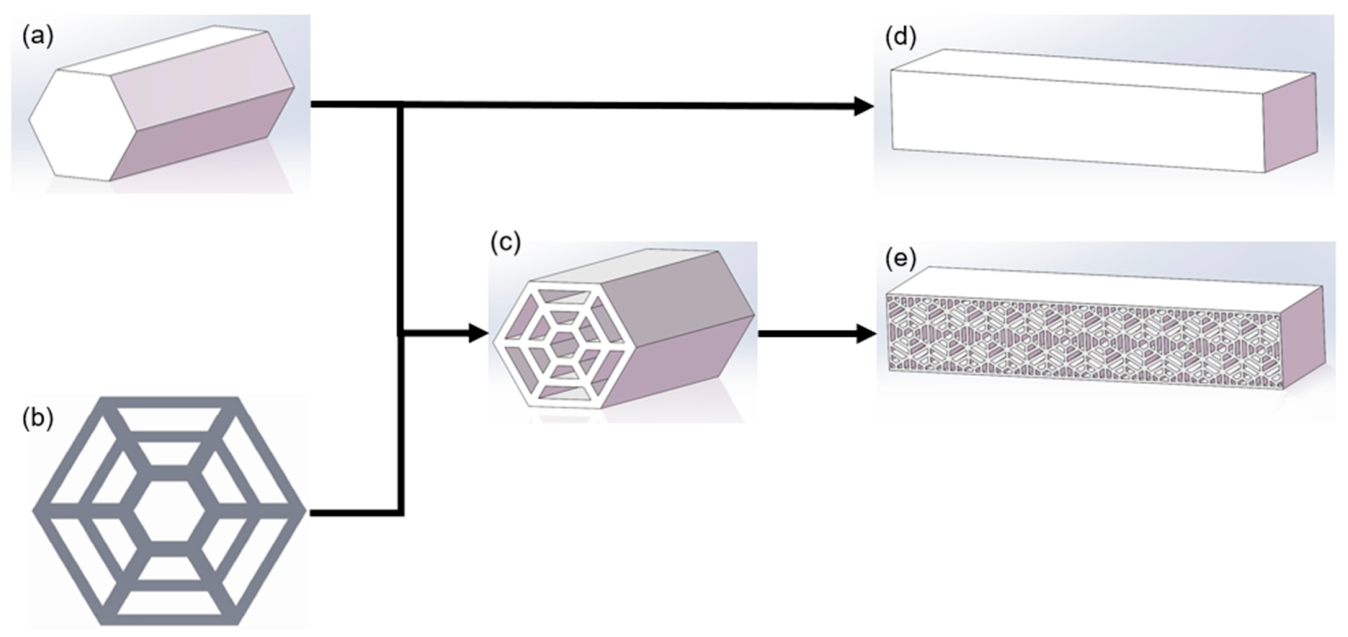
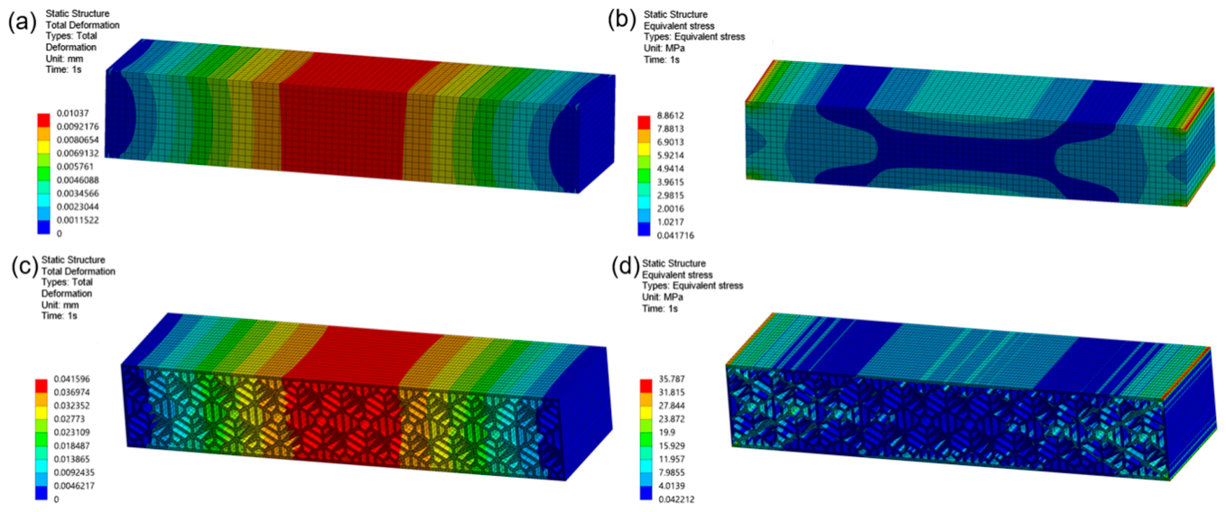
For the designed spider web simulation structure, one unit was selected for static simulation analysis, and the results are shown in the
Figure 5. Unless otherwise specified, the default material is PA6-CF.
The spider web structural unit exhibits unique mechanical aesthetic characteristics: under the same load, its deformation behavior shows an organic gradient change. The concentrated deformation of the centerline of the external force surface forms elastic folds similar to those of biological tissues under compression. This controllable deformation pattern not only optimizes mechanical properties but also creates dynamic visual rhythms. Comparing
Figure 5a,c, it can be seen that, compared to traditional structural units, the spider web structural unit undergoes greater deformation under the same load, but the deformation is concentrated on the external force surface and reaches its peak at the centerline of the surface. Looking at
Figure 5b,d again, the spider web structural unit shows significant changes in stress distribution compared to traditional structural units. The area of the high stress distribution region decreases, with the most significant reduction being the stress at the core, radial filaments, and outer surface edges within the unit. However, the stress on the centerline of the outer surface is more concentrated, and the stress peak is higher than that of traditional structural units. The support of the spider web unit structure mainly relies on radial filaments. Simulation results show that this structure can effectively concentrate high stress in noncritical structural areas, allowing the centerline of the stress surface to experience high stress and certain deformation to ensure that the stress on the radial filaments is reduced. This can improve the strength and elastic deformation ability of the entire structure.
From the perspective of lattice mechanics, the hexagonal spider web unit forms an orthotropic bionic lattice system composed of radial load-bearing filaments and circumferential capture filaments, which constructs a hierarchical stress transfer mechanism inside the unit. When external tensile load acts on the contact surface, the load path evolves in two stages: the primary load transfers along the radial filaments as the main force-bearing channel to disperse most axial tensile stress to the fixed support boundary; the secondary load is shared by the circumferential interwoven filaments to realize lateral shear stress redistribution. Unlike the solid uniform lattice of traditional structural units with disordered stress diffusion, the biomimetic lattice actively guides stress flow through the directional layout of filaments, realizing active regulation of load path evolution. This lattice-induced stress partitioning effect concentrates high strain energy on the contact surface with low structural safety weight, while the core radial skeleton bears low-amplitude stable stress, fundamentally reducing the risk of local fatigue failure of the main load-bearing structure.
Integrating the unit structure into a simple planar block for simulation provides an innovative path for product design to transform structural performance into visual narrative, elevating the roof handrail from a simple functional component to carrying a dialogue between technology and nature. The deformation and stress of different structured planes were tested under macroscopic loads, and the results are shown in
Figure 6.
From
Figure 6a,b, it can be seen that the planar blocks composed of spider web structural units will undergo greater deformation, which is consistent with the derivation of previous unit simulations. In the comparison of another set of images, the planar block composed of spider web structure has a larger low stress area under the same load and effectively reduces stress concentration, making stress distribution more uniform.
Therefore, the spider web unit structure can allow for greater stress and optimize stress distribution and improve elastic deformation ability and other characteristics that can be applied to roof handrails. While achieving the goal of lightweight roof handrails, it can further optimize handrail performance, enhance handrail user experience, and redefine the aesthetic of automotive interior objects, elevating roof handrails from simple practical components to artistic designs that carry technological humanism.
3.2. Simulation Analysis of Handrails with Different Structures
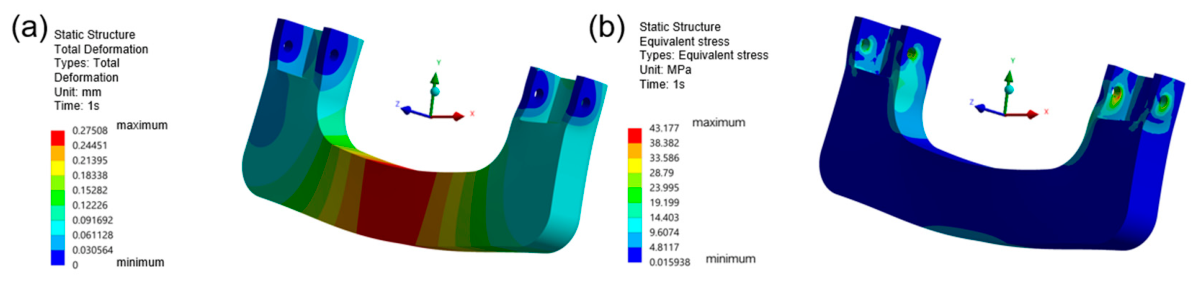
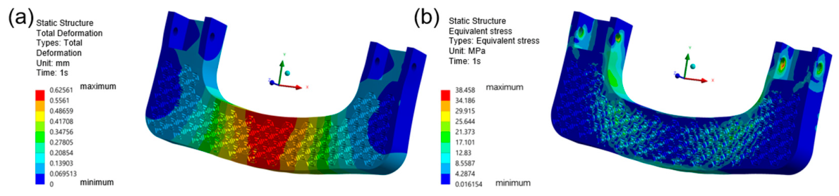
In order to gain a mechanical understanding of the basic handrail structure, static simulations were conducted on traditional roof handrails made of PA6-CF material under tensile loads of 500 N, 1000 N, and 1500 N. Partial results are shown in
Figure 7.
The specific simulation results are summarized in
Table 4.
Analysis of
Table 4 demonstrates that conventional handrail designs maintain stress distribution within PA6-CF material’s permissible strength thresholds under operational loads. On the other hand, the greater the tensile elastic deformation of the handrail structure, the more comfortable it will be for passengers to feel when using it. The Eight Trigrams Spider Web-inspired configuration achieves dual objectives of mass reduction and structural integrity [
27], while exhibiting enhanced mechanical performance characteristics. From previous simulation results, it can be seen that it can improve stress distribution, enhance the overall elastic deformation ability of the structure, and improve the user experience of the handrail. In addition, the spider web structure has a high tolerance for defects, and other defects have a relatively small impact on its own performance when the supporting structure is intact [
28]. Therefore, this study can remove a large number of redundant structures and simplify the spider web model.
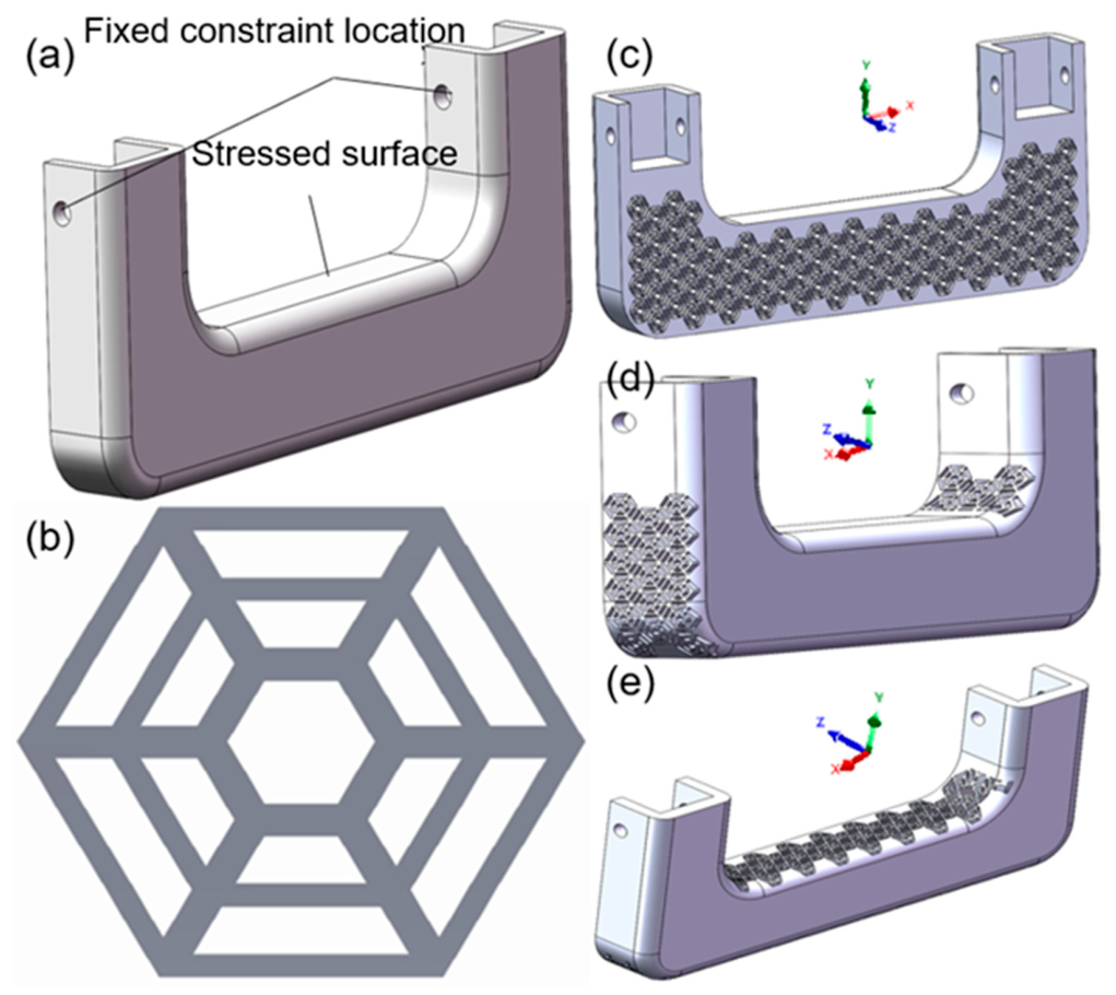
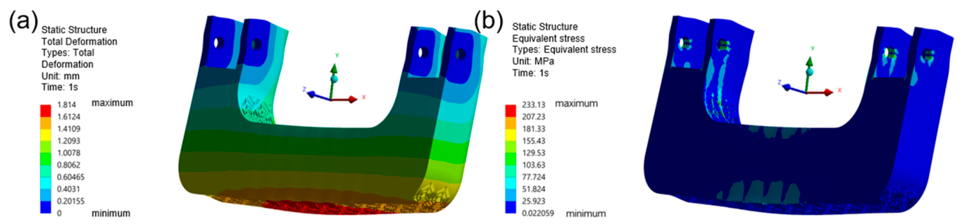
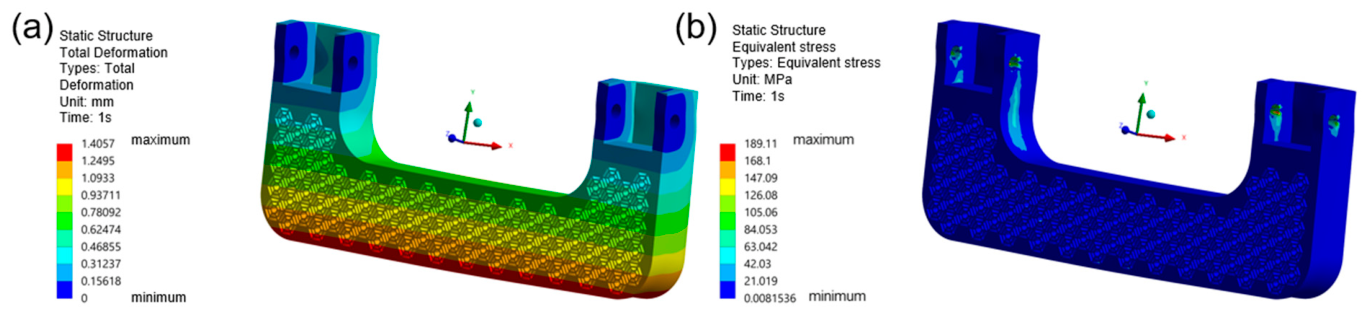
Apply tension of 500 N, 1000 N, and 1500 N to three new handrail design models. The images in this study only show the simulation results under a load of 1500 N. The total deformation diagram and equivalent stress diagram are shown in
Figure 8,
Figure 9 and
Figure 10.
After classifying and organizing the simulation data, record the simulation data with a load of 500 N in
Table 5. The analysis revealed that the
z-axis-oriented biomimetic configuration demonstrated minimal peak stresses compared to alternative directional designs. Structural mechanics principles indicate that reduced maximum stress values under loading conditions correlate with enhanced structural integrity and operational safety. Therefore, the spider web biomimetic structure designed in the
z-axis direction is more stable and safer.
Subsequent testing phases involving elevated tensions of 1000 N and 1500 N generated complementary datasets, which were systematically compiled in
Table 6. This hierarchical data organization facilitates progressive analysis of structural behavior across varying load intensities. Analysis of
Table 5 and
Table 6 reveals that
z-axis handrail designs exhibit higher equivalent stress values compared to conventional counterparts across multiple scenarios, though remaining within permissible material strength thresholds. In addition, if the total deformation increases without structural damage, it indicates that the new structure can improve elastic deformation to some extent. The
Z-axis design scheme has higher deformation under safe conditions. Consequently, the
z-axis spider web structural handrail demonstrates optimal performance under low-load conditions compared to alternative directional designs.
The PA6-CF material in this research comprises more than 25% carbon fiber content. This elevated carbon fiber concentration contributes to its brittle fracture characteristics [
29]. Such brittle substances align with the first strength theory principles. Experimental data from
Table 6 reveals that the peak equivalent stress in the
x-axis configuration design has surpassed the material’s tensile strength threshold, attaining 273.3 MPa. Under 1500 N loading conditions, the highest equivalent stress values exceed the permissible material strength parameters outlined in
Table 2. Consequently, the structural design demonstrates inadequate performance under elevated loading conditions.
When the load of the spider web biomimetic structure handrail designed in the y-axis direction reaches 1500 N, the peak equivalent stress has already exceeded the minimum conservative value of tensile strength. According to the first strength theory, there is a possibility of partial failure in the high stress concentration area inside. This phenomenon accelerates material fatigue development, thereby shortening the operational lifespan compared to z-axis designs. Comparative analysis reveals the z-axis configuration maintains equivalent stress levels below critical thresholds under identical loading conditions.
Further analysis of the overall load path evolution of three lattice layout schemes from macro mechanical perspective can explain the essential difference in their stress levels. For the X-axis and Y-axis biomimetic lattice, the stress cannot be continuously transmitted along radial filaments to the fixed constraint end, forming multiple stress stagnation zones inside the hollow lattice, which results in sharp stress concentration and excessive peak equivalent stress under 1000 N and 1500 N loads. In contrast, in the Z-axis spider web, the radial filaments form a continuous linear stress transfer channel from the grip surface to the fixed base, and the circumferential auxiliary filaments realize transverse load homogenization. The whole load path evolves smoothly without obvious stress blocking points, which restrains the maximum equivalent stress within the allowable range of PA6-CF and avoids premature material yield or fracture. The directional matching between lattice skeleton and main load vector is the core reason why the Z-axis layout balances lightweight, safety and elastic deformation performance.
The z-axis biomimetic handrail design demonstrates multiple performance advantages. Beyond ensuring structural safety compliance, computational models indicate potential mass reduction reaching 32.03% through optimized material distribution. This design configuration simultaneously enhances elastic deformation capacity while effectively minimizing peak stress concentrations.
3.3. Simulation Analysis of Handrails Made of Different Materials
From the previous analysis, this work has determined the superiority of the z-axis scheme. Therefore, the next step is to simulate and compare the materials. The new structural scheme only retains the Z-axis scheme.
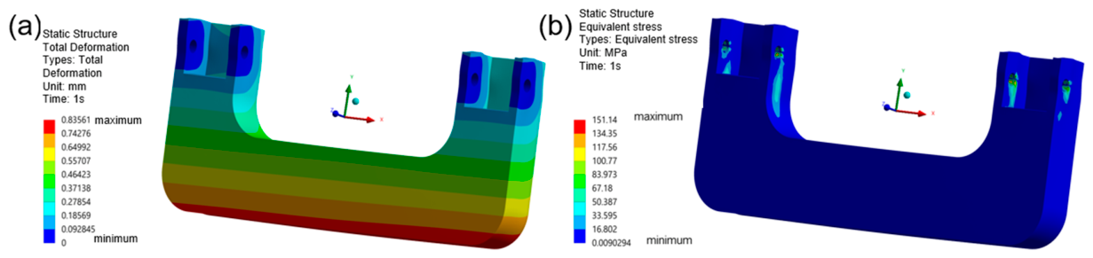
When a tensile force of 1500 N is applied to the traditional handrail made of PLA Basic material, the total deformation diagram and equivalent stress diagram are shown in
Figure 11.
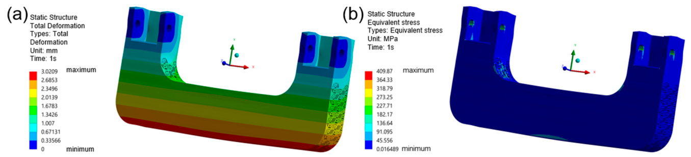
When a tensile force of 1500 N is applied to the handrail of PLA Basic material designed along the
z-axis, the total deformation diagram and equivalent stress diagram are shown in
Figure 12.
For the convenience of analysis and comparison, the simulation data that is not displayed will be organized together with the data in the above figure into
Table 7. By analyzing the simulation results, it can be concluded that PLA Basic material handrails have smaller equivalent stress peaks under the same load. However, handrails made of PA6-CF material have a greater maximum total deformation.
In order to clarify whether the handrails made of these two materials can be used, a safety factor index has been introduced. Under extreme loading conditions of 1500 N, the safety coefficients for biomimetic spider web structure handrails were computed. Experimental data from
Table 2 indicates PA6-CF’s tensile strength reaches 210 MPa compared to PLA-based material’s 50 MPa. As shown in
Table 7, peak equivalent stresses measure 189.1 MPa for PA6-CF and 38.5 MPa for PLA variants. Consequently, PA6-CF handrails demonstrate a safety factor of 1.11, while PLA-based units achieve 1.3, both exceeding the minimum requirement of 1.
However, this study emphasizes the coordination between handrail industry aesthetics and ergonomics. The PA6-CF material exhibits superior elastic deformation characteristics, enabling enhanced adaptability for optimizing user experience through innovative design solutions. The difference in elastic deformation and stress response between the two materials can also be explained by the coupling law of material anisotropy and lattice stress transfer mechanism. PLA Basic is an isotropic polymer, and the load path inside the spider web lattice evolves uniformly in all directions without directional bias; the stress transfer efficiency of radial and circumferential filaments is consistent, so the overall stress peak is low but the elastic energy storage capacity is limited. As a carbon-fiber-reinforced anisotropic composite, PA6-CF forms a dual-level stress transfer system; the bionic spider web lattice dominates the macroscopic load path distribution, while the internal carbon fiber orientation dominates the microscopic interlayer stress transmission. Under tensile load, the load path evolves along the fiber direction consistent with radial filaments, which improves the axial stress transfer efficiency of the lattice, enhances the elastic deformation energy dissipation capacity of the whole structure, and provides a buffer effect for human grip impact load. This coupling effect of biomimetic lattice layout and fiber anisotropic reinforcement realizes the coordinated evolution of load path and stress transfer channel under dynamic human–computer interaction load.
4. Testing Results
Simulation models of
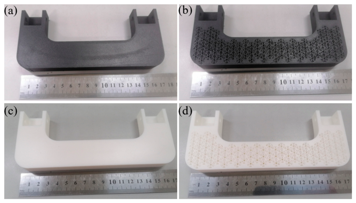
z-axis spider web biomimetic designs indicate a simulated weight reduction ratio of approximately 32.03%. However, errors are inevitable in actual production, so the sample handrails are processed and then weighed.
Table 8 summarizes the results. This study used an electronic balance for sample weighing.
As evidenced in
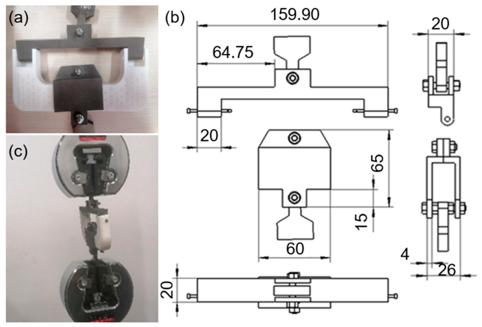
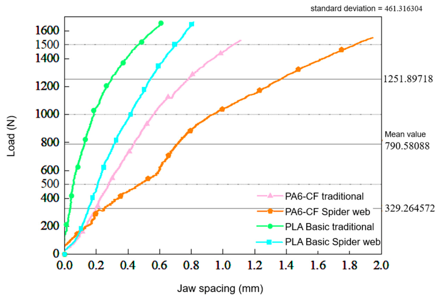
Table 8, PA6-CF handrails incorporating bio-inspired spider web configurations demonstrate mass reduction percentages around 26.19%, whereas PLA-based counterparts achieve approximately 28.16% weight reduction. These empirical measurements validate the significant promise of spider web biomimetic architectures for weight reduction applications. Computational simulations further reveal that PA6-CF composite handrails with such bio-structures exhibit superior mechanical characteristics. Experimental testing can obtain more data to demonstrate the practical application capability of the proposed solution. The experimental result data chart is shown below.
From
Figure 13, it can be seen that, when the load is 1500 N, the actual test results are greater than the simulation results, but the curve in the figure does not show a sudden drop, which means that the handrail has not undergone structural damage. All handrail structures have qualified strength, and the overall deformation pattern is consistent with the simulation results.
Comparative analysis of structural variations in handrail systems reveals distinct deformation characteristics. The spider-web-inspired configuration demonstrates a flatter deformation curve compared to conventional designs, suggesting enhanced elastic deformation capacity. All tested specimens maintained elastic behavior without reaching yield points, as evidenced by their linear deformation curves. Therefore, this indicates that the spider web structure improves the elastic deformation ability of handrails and enhances their energy dissipation ability [
30], mirroring computational modeling predictions. Such structural optimization potentially increases functional durability while maintaining ergonomic performance in practical applications.
Comparative analysis of handrail materials revealed that PA6-CF composites exhibit superior elastic deformation characteristics compared to PLA-based structural counterparts. The elastic deformation phase dominates all material responses illustrated in
Figure 13. This behavior stems from PA6-CF’s enhanced toughness properties [
31], which enable greater elastic strain accommodation under mechanical loading while maintaining structural integrity. The material’s balanced performance profile makes it particularly suitable for ergonomic applications requiring both safety compliance and user experience optimization.
The biomimetic spider web design implemented with PA6-CF material achieves multiple engineering objectives: substantial weight reduction in automotive handrail components, maintenance of structural strength requirements, and compliance with vehicular safety standards [
32]. This innovative approach simultaneously enhances user comfort in automotive environments and embodies the modern philosophy of “technologically-driven human-centric design”.
5. Conclusions
By combining bionics and additive manufacturing technology, a lightweight design of the roof handrail has been achieved, and a new scheme for the spider web biomimetic structure roof handrail made of PA6-CF material has been proposed. The unique value of additive manufacturing in connecting the “natural logic engineering technology experience design” chain has been verified through the case of the spider web biomimetic roof handrail. Its innovation is reflected in:
First, the parametric numerical modeling of the natural spider web structure is simplified and converted into models suitable for FDM processes. The eight-angle spider web biomimetic configuration is used as a lightweight solution for the handrail system. Then, the strength and deformation distribution characteristics of the spider web structure at different scales are analyzed through the layered simulation of micro-elements and plane modules.
Through investigating the functional–aesthetic synergy of PA6-CF composite material, simulation analyses revealed that the spider-web-inspired biomimetic configuration effectively enhances stress dispersion patterns and elevates elastic deformation capacity. Leveraging these findings, three distinct arachnid-web-inspired handrail prototypes were engineered, establishing an innovative “visualized performance” interactive paradigm.
Comparative evaluation of the tripartite biomimetic configurations and novel handrail assemblies demonstrated that z-axis design optimization presents the optimal approach, effectively balancing ergonomic requirements with mechanical performance by minimizing stress concentration across diverse operational scenarios. The spider-web-inspired PA6-CF handrail fabricated using 3D printing technology demonstrates a theoretically calculated weight loss of 32.03% relative to conventional designs, with practical implementation achieving approximately 26.19% weight savings.
Through computational modeling and experimental testing comparing material performance, the PA6-CF composite demonstrated superior characteristics over PLA substrates. Findings from both simulation and physical testing indicated that PA6-CF handrails exhibit enhanced elastic deformation capacity under equivalent loading conditions compared to PLA basic alternatives, fulfilling critical safety standards and impact absorption requirements while simultaneously improving ergonomic performance.
This study verified the application potential of spider web bionic structure combined with additive manufacturing in the lightweight design of automotive roof handles. Based on the current research results, the follow-up work is planned as follows: Conduct fatigue tests and mechanical simulations under alternating load, impact load and extreme temperature conditions to evaluate the long-term service performance and environmental adaptability of the bionic structure. Apply topology optimization algorithm to further optimize the layout and size parameters of the spider web structure, so as to achieve better lightweight effect while maintaining structural safety. Optimize the fused deposition molding process and material ratio to reduce the anisotropy of 3D printed carbon-fiber-reinforced PA6 composites and improve interlayer bonding strength. Carry out ergonomics tests and subjective sensory evaluation to establish a quantitative evaluation system integrating mechanical performance, structural form and user experience. Extend the bionic design method to other automotive interior functional parts, and complete real vehicle road tests and NVH tests to promote the industrial application of the proposed design. Explore the integration of multifunctional composite materials, digital twin technology and recycled additive manufacturing, and develop intelligent and eco-friendly bionic design solutions for automotive interior components.