Article

Vertically Aligned Boron Nitride Fiber Paper Thermal Interface Materials with High Electrical Insulation for Electronics Heat Dissipation

1
School of Materials Science and Engineering, Sun Yat-Sen University, Guangzhou 510275, China
2
School of Locomotive and Rolling Stock, Guangzhou Railway Polytechnic, Guangzhou 511300, China
*
Authors to whom correspondence should be addressed.
J. Compos. Sci. 2026, 10(7), 351; https://doi.org/10.3390/jcs10070351
Submission received: 16 March 2026 / Revised: 29 April 2026 / Accepted: 6 May 2026 / Published: 30 June 2026
(This article belongs to the Section Composites Applications)

Abstract

Effective thermal management is critical for ensuring the reliability of modern high-power electronic devices, where thermal interface materials (TIMs) play key roles in minimizing contact resistance and improving heat dissipation. Boron nitride (BN) is widely used as a thermally conductive filler due to its high in-plane thermal conductivity and electrical insulation. However, achieving BN-based polymer composites that simultaneously offer high filler loading, flexibility, and high thermal conductivity (κ) remains a significant challenge. In this work, we introduce a novel two-step fabrication strategy to overcome this limitation. First, continuous BN fibers with high aspect ratios are assembled into BN fiber papers with enhanced fiber alignment. These papers are then cut and integrated into a silicone matrix to form well-oriented thermal conductive channels. This approach enables a significantly higher filler mass fraction of 70%, resulting in a thermal pad with a high κ of 19.23 W/(m·K), low thermal resistance of 1.61 cm2·K/W, and excellent electrical insulation and flexibility. Application tests further demonstrate superior heat dissipation performance and operational stability compared to commercial silicone pads. This work not only highlights the potential of BN fiber-based TIMs but also offers a feasible process for their large-scale manufacturing.

1. Introduction

The rapid development of emerging technologies such as artificial intelligence and 5G communications has driven electronic devices and chips toward miniaturization and integration, which drastically increases heat flux densities per unit area. Excessive thermal accumulation can substantially degrade chip performance, accelerate device aging, and potentially lead to catastrophic failure [1,2,3,4,5]. TIMs, functioning as essential conduits between heat sources and heat dissipation systems, play an important role in contemporary thermal management [6,7,8].
The optimization of heat dissipation performance in TIMs fundamentally relies on reducing thermal impedance through the following three primary pathways: minimizing bond line thickness (BLT), decreasing thermal contact resistance (TCR), and enhancing intrinsic thermal conductivity. Both BLT and TCR are significantly influenced by the hardness of the materials used [9,10,11,12]. A key strategy for improving these properties involves the incorporation of thermally conductive fillers into a polymer matrix. The polymer matrix enables the composite TIMs to maintain good flexibility, while the thermal conductive fillers compensate for the deficiency of the thermal conductivity property. By controlling the proportion of each component, the balance between compliance and thermal conductivity can be adjusted. Currently, the most representative types of thermal conductive fillers include metallic particles (silver and aluminum) [13,14], carbon-based materials (graphene and carbon nanotubes) [15,16,17], and electrically insulating ceramics (e.g., boron nitride and aluminum oxide) [18,19]. Each of these fillers contributes uniquely to the overall performance of the TIMs, allowing for tailored solutions to specific thermal management challenges.
Hexagonal boron nitride (h-BN) is a promising material due to its exceptional in-plane thermal conductivity (κ), exceeding 300 W/(m·K), along with superior chemical inertness, corrosion resistance, and mechanical robustness. Additionally, h-BN exhibits outstanding electrical insulation properties. In conventional methods, thermally conductive fillers such as BN are particle typed fillers and randomly distributed within the polymer matrix, resulting in insufficient direct contact between the fillers, exacerbating phonon scattering and leading to isotropic thermal performance in the material, which hinders the development of anisotropic thermal interface materials with κ greater than 10 W/(m·K). Orientation is an effective way to enhance the κ of material for anisotropic fillers. Various approaches have been employed to achieve highly vertically oriented BN structures in polymers. These methods include electric field alignment [20], magnetic field orientation [21,22,23], 3D printing [24,25], expansion flow-assisted assembly [26], layer-stacking cutting [27,28,29], freeze-drying alignment [30,31] and hot-pressing [32,33]. Such strategies facilitate more efficient heat flux propagation along the oriented filler networks, resulting in significant enhancements in κ. However, the intrinsic high thermal resistance between BN and polymers still cannot be avoided, leading to non-optimal thermal performance [34,35,36,37,38,39,40].
In contrast to BN particles, one-dimensional (1D) BN fibers have demonstrated exceptional promise in aerospace communication systems, particularly for thermal management application [41]. The anisotropic properties of 1D fibrous materials may solve the problem directly by providing a continuously heat transport channel in polymer matrix. Previously, we successfully fabricated vertically aligned BN fiber thermal pads, which exhibited a κ of 16.77 W/(m·K) and a thermal resistance of 2.33 cm2·K/W at a maximum filler mass of 40% [42]. This result is reasonable considering that the thermal conductivity of a single BN fiber ranges from approximately 40 to 55 W/(m·K) [43], which is significantly lower than the BN theoretical value. Hence, the BN thermal pads need to incorporate large volume amount of BN fibers to achieve high κ (i.e., 50 wt% for 20 W/(m·K)). However, it is difficult to achieve a high loading in silicone gel or other adhesives owing to the chemical inertness of BN materials. The maximum filler rate for BN fiber thermal pads fabricated through manual molding is about 25%. While hydraulic pressure molding with effective sealing can increase the filler loading to 45 wt%, further additions lead to fiber breakage during compression. Additionally, if the filler loading becomes excessively high, the thermal pad may become too rigid for practical applications. To address these challenges, we modified the traditional manufacturing process into a two-step strategy. Firstly, horizontally aligned BN fiber paper (H-BNFP) was fabricated via a hot-pressing method. H-BNFP serves as an efficient thermal conductivity pathway in thermal pads. The final thickness of the paper is controlled to below 0.2 mm, ensuring that a massive fracture will not occur in the H-BNFP thermal pad, even under extremely high filler loading conditions (i.e., >70%); thus, a continuous thermal pathway can be retained. Secondly, the papers were cut into strips, each of which was essentially a flexible fiber bundle. The strips were then mixed with silicone gel and subjected to hydraulic mold pressing to form a fiber–=silicone gel composite block. Thermal pad samples were subsequently cut from the composite block. Through this two-step method, the thermal pad allows for a higher filler loading, with superior κ (70 wt%, 19.23 W/(m·K)) and low thermal resistance (50 psi, 1.61 cm2·k/W) while maintaining good mechanical properties. Our work demonstrates the viability of 1D h-BN fiber architecture as next-generation TIM solutions for high-power-density electronics requiring simultaneous thermal management and electrical isolation capabilities.

2. Experimental Section

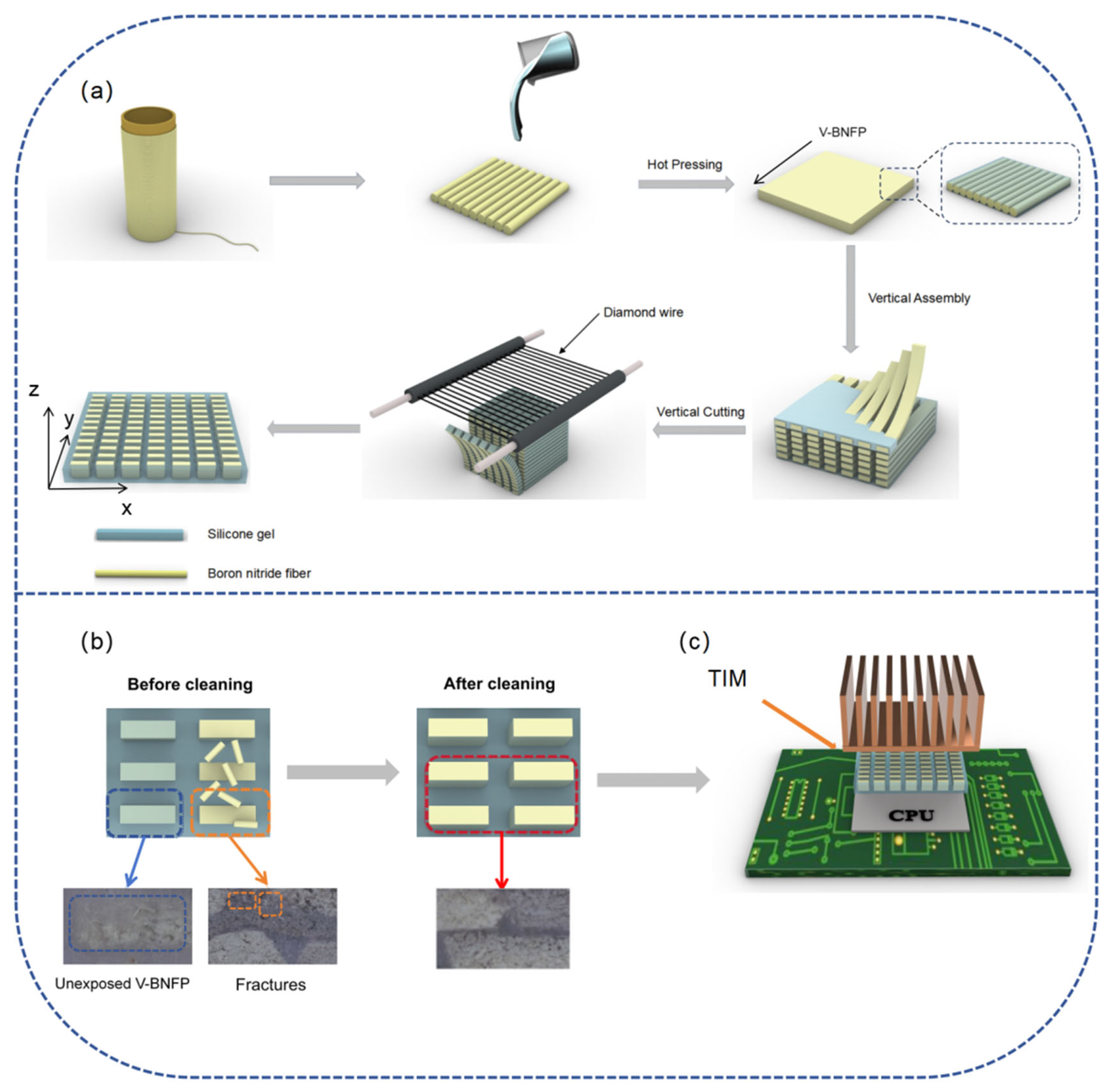
A two-step approach is used to fabricate flexible BN fiber thermal pads with a high filling rate. The fabrication process is schematically illustrated in Figure 1.
The continuous BN fibers were firstly cut into the same length and oriented parallel to each other. In order to accurately encapsulate the BN fibers, a silicone gel consisting of parts A and B at a 1:1 ratio was then added to the mold and evenly dispersed using a manual dispenser blade. After curing at 80 °C for 3 h, the H-BNFPs were prepared. This process effectively restricts the relative sliding between the BN fibers and enhances their vertical orientation.
Next, H-BNFP was sliced into uniform strips and each strip of the H-BNFP was coated with another harder type of silicone gel and horizontally stacked in the mold. To eliminate the air bubbles and redundant silicone gel within the composite, it is necessary to use cold pressing process to the composite. The redundant silicone gel escapes through the side holes of the stainless-steel mold, which contributes to form a more compacted and uniform H-BNFP and silicone gel composite. Subsequently, the H-BNFP composite was cured at 100 °C for 4 h to produce the block of H-BNFP. For the purposes of preventing shear-induced damage to vertically oriented structure and reducing the surface roughness during the cutting process, the block was immersed in a liquid nitrogen atmosphere for an additional 30 min in advance to keep the block hard. Finally, a diamond-wire cutting machine was used to cut the block perpendicularly, yielding vertically aligned thermal pads with a thickness of 0.8–2 mm. By adjusting the quantity of H-BNFP used in the stacking process, blocks with varying BN fiber contents ranging from 0 wt% to 70 wt% were fabricated.
After cutting with the diamond wire, the surface of the thermal pad was contaminated with a layer of stain composed of residual silicone, BN fibers, etc., from the cutting process between the diamond wire and the frozen composite, which significantly impaired heat transfer efficiency. Therefore, the thermal pads were immersed in the silicone dissolving agent (DY-711) and subjected to ultrasonic cleaning for 15 min. Subsequently, they were thoroughly rinsed with deionized water to remove residual solvent. Finally, the thermal pads were obtained after polishing with high-grit sandpaper, and continuous vertical thermal conduction paths formed by H-BNFP can be observed on the surface. This ensured effective contact between the vertically aligned boron nitride fiber paper (V-BNFP) thermal pad and the surface of the heat source and heat sink, thereby improving the heat dissipation efficiency.

3. Materials

The BN fibers (density of 1.60–1.79 g/cm3) were provided by the Shandong Industrial Ceramics Research and Design Institute, Zibo, China. Silicone gel (parts A and B, Ecoflex series 00–20, viscosity of 3000 cps) and another harder type of silicone gel (parts A and B, Ecoflex series 00–30, viscosity of 3000 cps) were both purchased from Shenzhen Feilong Zhaofu Technology Co., Ltd., Shenzhen, China. The silicone dissolving agent (DY-711) was supplied by Shenzhen Ruisheng Technology Co., Ltd., Shenzhen, China.

4. Characterization

An optical microscope (HDMI AP200C, Autel Intelligent Technology Corp., Ltd., Shenzhen, China) was used to characterize the surface of the thermal pad. A field-emission scanning electron microscope (FESEM, SU3800, HITACHI, Tokyo, Japan) equipped with an energy-dispersive spectrometer (EDS), provided by Oxford Instruments, was utilized for further microstructural examinations. The roughness of the sample’s surface was characterized by a confocal laser scanning microscope (LEXT OLS4100, Olympus, Tokyo, Japan). Thermogravimetric analysis (TGA) was conducted using a TGA2 (METTLER TOLEDO, Greifensee, Switzerland) with a heating rate of 10 °C/min from 25 °C to 800 °C in a N2 atmosphere (50 mL/min). A universal mechanical testing machine (CMT 4304, SUST, Shenzhen Xinsansi Jiliang Instrument Corporation, China) was used to measure the compressive stress and modulus with a loading rate of 1 mm/min. The 1D X-ray diffraction (XRD) spectra were recorded using an X-ray diffraction system (D8 ADVANCE, BRUKER, Mannheim, Germany) at 40 KV with Cu Kα radiation (λ = 1.54 Å) at room temperature. Raman spectroscopy (Horiba LabRAM HR Evolution, Tokyo, Japan) was employed to assess the crystallinity of the BN fibers. The thermal diffusivity (α) of thermal pads at room temperature were measured by a laser flash analyzer (LFA1000, LINSEIS, Selb, Germany). The density(ρ) was measured by a density analyzer (MD3002G, XIUILAB, Shanghai, China) based on the Archimedes principle. The specific heat capacity (Cp) was obtained through differential scanning calorimetry (DSC3, METTLER TOLEDO, Greifensee, Switzerland). The thermal resistance was measured by Longwin 9389 thermal conductivity tester according to the ASTM D5470 standard [44]. A precision impedance analyzer (Agilent-4294A, Agilent-4989A, Agilent Technologies, Santa Clara, CA, USA) was used to measure the dielectric constant and dielectric loss of thermal pads and BN fibers. The volume resistivity of films was tested by a digital source meter (Keithley 2400, Tektronix, Beaverton, OR, USA). The DC breakdown strength of the sample was measured using a DC withstand voltage tester (RK2674A, Rek, Shenzhen Meiruike Electronic Technology Co., Ltd., Shenzhen, China). The surface temperature of the thermal pad was captured by a thermal infrared image instrument (Ti300, FLUKE, Everett, WA, USA).

5. Results and Discussion

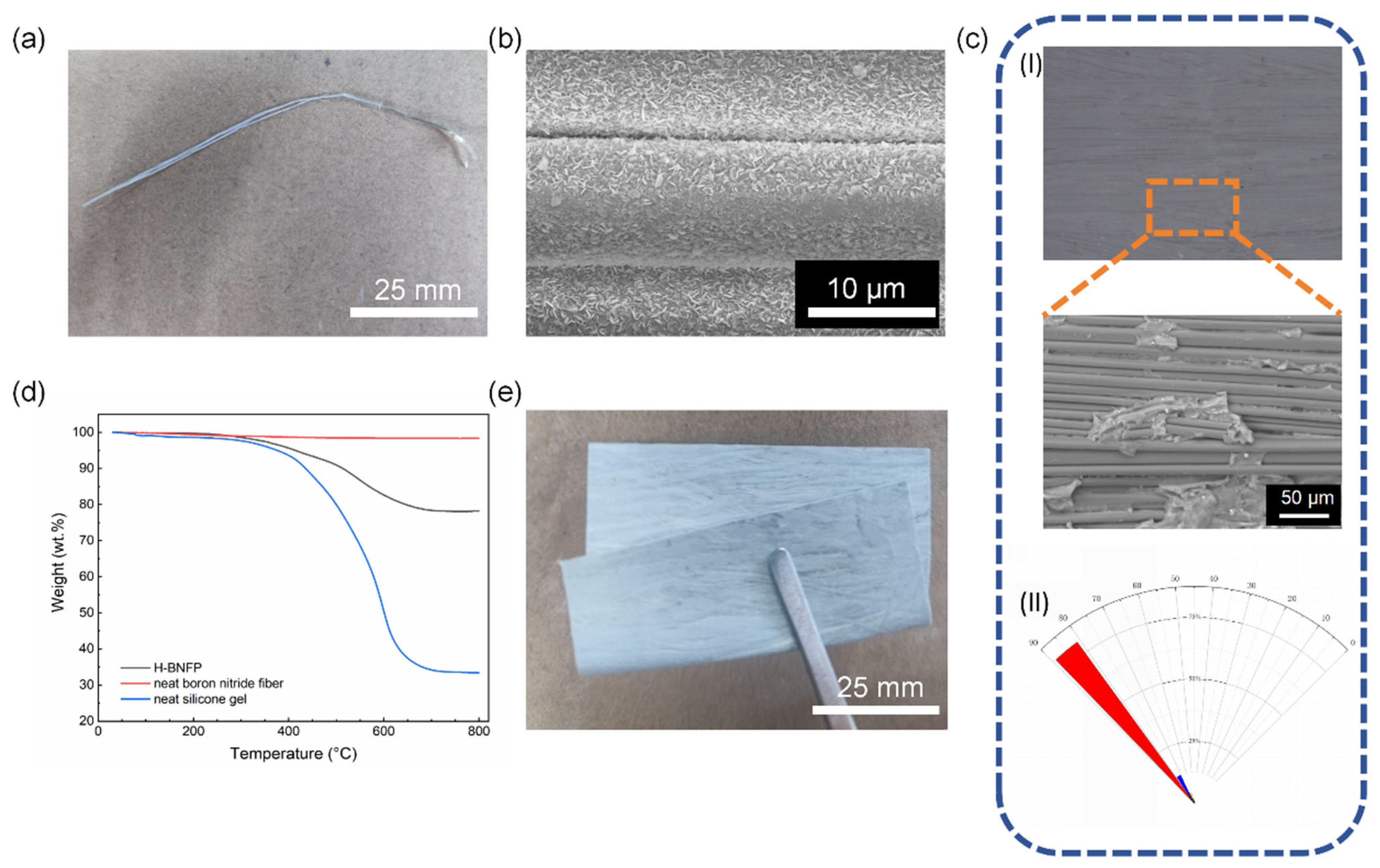
Figure 2a,b present an optical photograph and SEM image of the BN fiber. These images reveal tightly arranged boron nitride nanosheets (BNNSs). Although the BNNSs are not specifically aligned, their interconnected structure minimizes the contact area with the silicone matrix, effectively suppressing interfacial phonon scattering. This characteristic significantly enhances the thermal conductivity of the composite material. Figure S1a,b present representative SEM images illustrating the typical diameter and length of the boron nitride fibers. The fibers exhibit diameters of less than 10 μm and possess considerable lengths. The exceptionally high aspect ratio of the fibers facilitates the formation of continuous thermal conduction pathways that penetrate through the thickness of the thermal pad from the top to the bottom surface. To evaluate the degree of crystallization of the BN fibers, an XRD analysis and Raman spectra are performed. The XRD analysis is presented in Figure S2a, revealing distinct diffraction peaks at 2θ values of 26.8°, 41.6°, 55.2°, and 75.9°, which correspond to (002), (100), (004), and (110), respectively. These diffraction features exhibit a high degree of consistency with the diffraction patterns observed for commercial BN powder, as well as the standard reference PDF card for BN. As shown in Figure S2b, the Raman spectrum of the BN fibers exhibits a typical E2g phonon mode of BN at 1365 cm−1, with a full width at half maximum (FWHM) of 13.9 cm−1. This value closely approximates the FWHM of 13.3 cm−1 recorded for commercial BN powder, indicating a notably high crystalline quality of the BN fibers. Due to the chemical inertness and weak intermolecular forces of the BN fibers, it is extremely challenging to obtain pure H-BNFP and thermal pads while maintaining adequate mechanical properties. Consequently, introducing a second phase, such as silicone gel, is essential for developing H-BNFP and thermal pads that exhibit adequate mechanical performance. Figure 2c displays a photo and SEM image of the H-BNFP, where closely packed BN fibers are distinctly visible. These fibers provide continuous phonon transport pathways, thereby facilitating the improvement in κ. ImageJ (version: 20250529–2217) software is utilized to evaluate the degree of orientation of BN fibers in the H-BNFP. The BN fibers are arranged highly parallel to each other, and more than 80% of the BN fibers have an angle of over 80° with the x-axis, which further demonstrates the presence of numerous vertical and efficient thermal conduction pathways within the thermal pad. Figure S3 shows a cross-sectional SEM image of the H-BNFP. The BN fibers are well encapsulated by the silicone gel, revealing no apparent gaps or voids at the fiber–matrix interface. To ascertain the content of BN fibers in the H-BNFP, TGA was performed, and the results are presented in Figure 2d. Given that the h-BN fibers maintain structural stability when heated to 800 °C in a nitrogen atmosphere, and the residual silicone content reaches 38%, the calculated mass fraction of the h-BN fibers in the H-BNFP yields 73%. This value represents the maximum feasible filler loading in the H-BNFP while preserving satisfactory mechanical integrity. As shown in Figure 2e, the H-B/NFP exhibits excellent bendability and mechanical properties. Exceeding this threshold would induce significant mechanical degradation in the composite.
Figure 3a–c illustrate optical images of the V-BNFP thermal pad. The H-BNFP are found to be densely arranged. The H-BNFP content within the thermal pad is determined through the following Equation (1):
H-BNFP   content = m H B N F P m b l o c k × 100 %
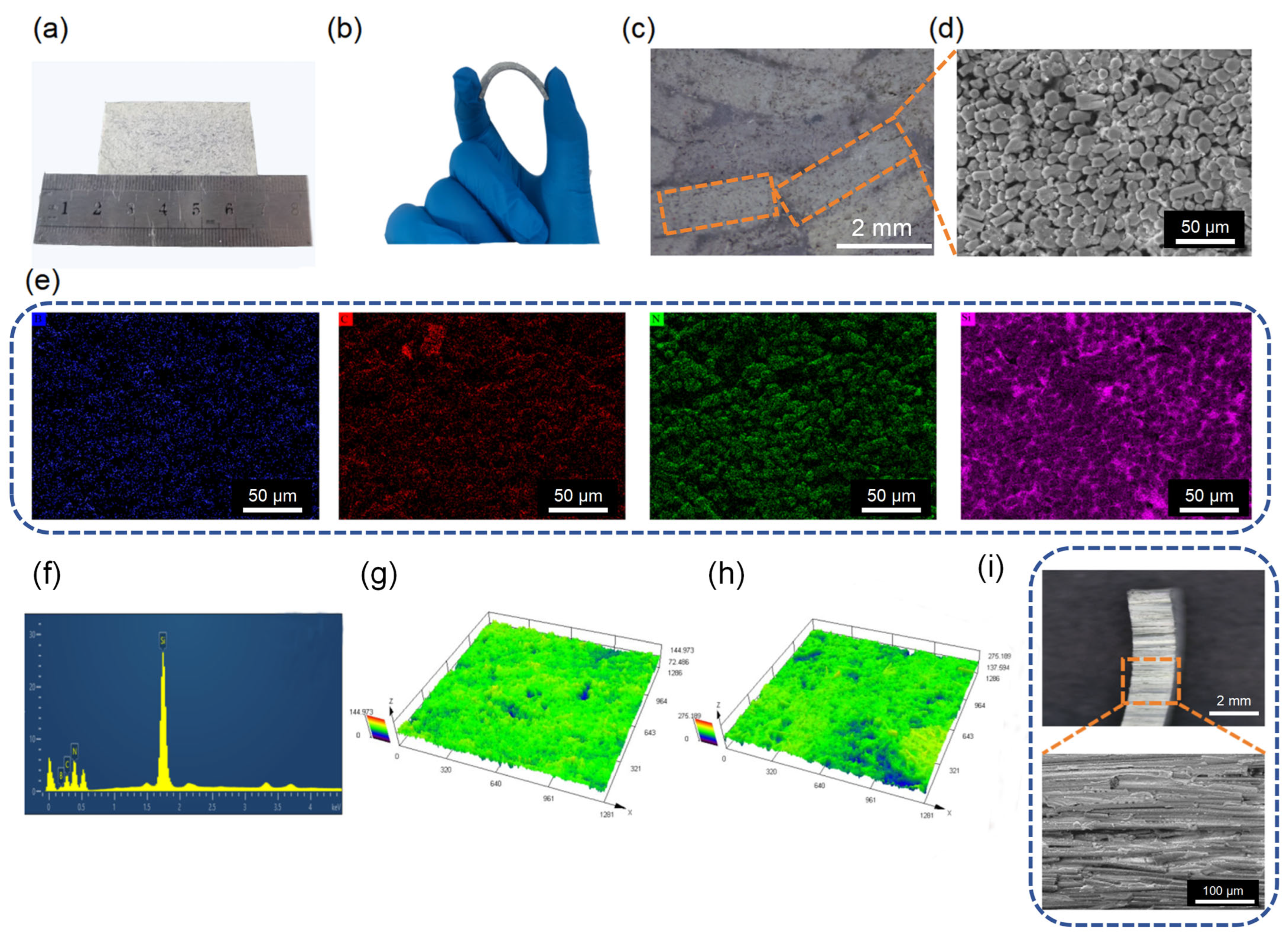
where m H B N F P and m b l o c k represent the mass of the block obtained before the diamond-wire cutting and the mass of H-BNFP used in the manufacturing process, respectively. Thermal pads with mass fractions of 18%, 45%, and 70% were prepared. Remarkably, even at a high content of 70%, the thermal pad still exhibits good compliance and mechanical properties as presented in Figure 3b. The SEM image and EDS elemental analysis and distribution of the thermal pad surface are depicted in Figure 3d,e. Silicone gel fills the considerable air channels existing between the H-BNFP, which contributes to lower thermal resistance and excellent flexibility of the thermal pad. Figure 3e,f illustrate the element distribution of B, C, N, and Si, which confirm that V-BNFP are adequately wrapped by the silicone matrix. The presence of impurities on uncleaned thermal pad surfaces deteriorates their thermal performance. Figure 3g,h indicate the surface roughness of thermal pad before and after solvent cleaning. After cleaning, silicone residues and fiber fragments are removed, exposing the underlying fiber structure, which leads to an increase in surface roughness. This promotes more effective contact with both the heat sink and heat source, thereby reducing thermal resistance. Figure 3i is the optical and SEM images of the cross-section of the thermal pad, in which it is apparently observed that the silicone matrix provides robust mechanical support for the vertically arranged and high-efficiency thermal conduction pathway H-BNFP. Moreover, it is evident that the basal planes of BN platelets maintain a dense and overlapping structure.
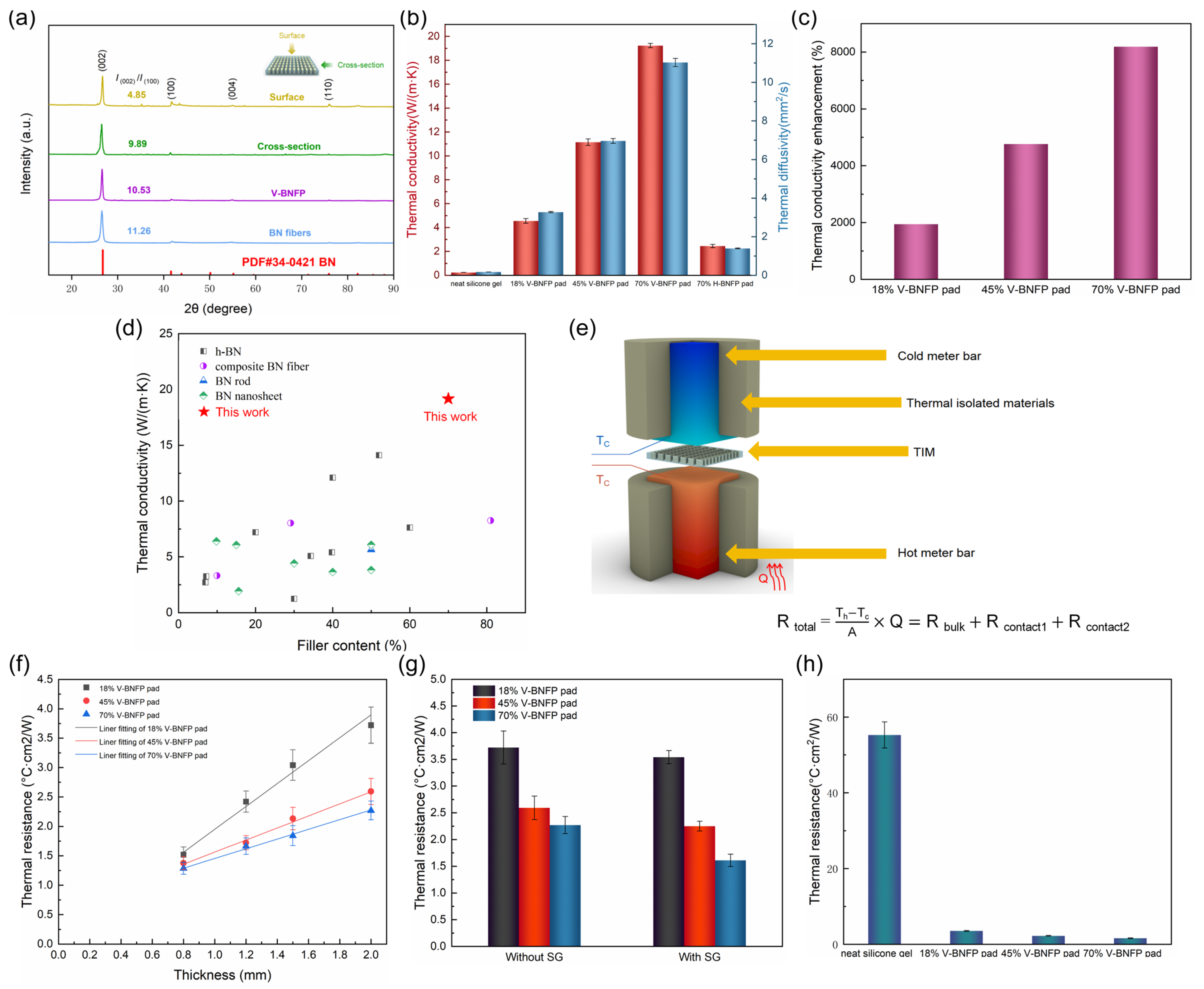
The BN fibers are composed of a large number of BNNSs, as indicated previously in Figure 2b. The in-plane κ of the (002) crystal plane is higher than that of the (100) plane. Therefore, a higher intensity ratio of the (002) to (100) peaks correspond to a higher κ of BN fibers and the thermal pads. The XRD measurement was employed to investigate the preferred orientation of the BNNS. Figure 4a displays the characteristic diffraction peaks of BN fibers and composites are 26.7° and 41.6°, corresponding to the (002) and (100) crystal plane, respectively, along with their XRD intensities. A dimensionless parameter, δ , is introduced to evaluate the degree of orientation of BN fibers and composite, which can be defined in the following equation:
δ = I 002 I 100
where I 002 and I 100 represent the peak intensities of (002) and (100) crystal planes, respectively. Previous studies have demonstrated that a larger value of δ is more conducive to the formation of anisotropic composites with high thermal conductivity [28,45]. The value of δ is quite similar in BN fibers and H-BNFP, which proves that the BN fibers are neatly parallel arranged in the H-BNFP. When X-rays are incident from the top, the value of the δ is 9.89, and the δ drops to 4.85 when X-rays are incident from the side. This difference implies that although the BNNS distribution appears random at the microscale, the nanosheets still exhibit a preferred orientation consistent with the parallel alignment of the BN fibers, thereby contributing significantly to the high κ for the products. Compared to directly using BN fibers as thermal conductive fillers, employing H-BNFP as fillers can not only increase the filler content in thermal pads but also achieve a high degree of orientation. Based on a large number of continuous H-BNFP, the thermal pad is expected to possess a wonderful through-plane thermal conductivity ( κ ). The thermal diffusivity of the thermal pad with a thickness of 2 mm is measured by the laser flash method, and the measurement is performed three times. The κ of the composite is calculated by the following equation:
κ = α × ρ × c p
where α, ρ, and cp, are the thermal diffusivity, density, and specific heat capacity of thermal pad, respectively. The corresponding results are presented in Table S1. As shown in Figure 4b, the highest value of κ and α are 19.23 W/(m·K) and 11.03 mm2/s at a 70 wt% H-BNFP loading. Notably, the in-plane thermal conductivity (κ) of the 70% V-BNFP thermal pad (equal to the κ of the 70% H-BNFP pad) is only 2.66 W/(m·K), revealing a sharp decline in heat transport when heat flux is perpendicular to fiber alignment. This results from high filler-matrix interfacial thermal resistance caused by phonon spectrum mismatch and strong interface scattering [46]. Since filler–matrix resistance is far higher than filler-filler resistance, it is essential to avoid orienting the heat flux perpendicular to the fiber alignment direction. Furthermore, the V-BNFP thermal pads are unidirectionally fiber composite, the κ of the pad can be predicted using the parallel model illustrated in Figure S4, and the corresponding calculation is as follows:
κ = κ f i l l e r V + κ m a t r i x 1 V
where κ f i l l e r and κ m a t r i x represent the thermal conductivities of the filler and the silicone matrix, respectively. V represents the volume fraction of the filler. The calculated thermal conductivity of the 70% V-BNFP thermal pad is 18.56 W/(m·K), which is close to the value obtained by the laser flash method.
To more intuitively evaluate the contribution of BN fibers to the thermal conductivity of TIMs, the thermal conductivity enhancement (TCE) is introduced and defined as follows:
T C E = κ T I M s κ m a t r i x κ m a t r i x × 100 %
where κ TIMs and κ matrix represent the thermal conductivity of the TIMs and silicone matrix, respectively. As depicted in Figure 4c, the κ of the TIMs is up to 81.89 times greater than the matrix. The vertically arranged BN fibers serve as a high-speed pathway for phonons, which play a crucial role in the high κ of the TIMs. Due to the continuous thermally conduction path from the bottom to the top provided by H-BNFP, the κ of V-BNFP thermal pad surpasses that of most h-BN, BNNSs, and composite BN fiber-based thermally conductive composites, as illustrated in the Figure 4d. Meanwhile, we also compare the κ of our work with other TIMs of thermal conductive fillers, and the results are shown in Table S2 [69,70,71,72,73,74,75,76,77,78,79,80]. Thermal resistance is one of the necessary considerations for evaluating the performance of TIMs. The measurement principle of thermal resistance according to the ASTM D5470 standard is demonstrated in Figure S5, and the total thermal resistance (Rtotal) is measured as illustrated in Figure 4e. The Rtotal includes bulk thermal resistance (Rbulk), contact thermal resistance with the heat source and heat sink (Rcontact1 and Rcontact2). The Rcontact is determined by measuring the Rtotal of thermal pads with varying thicknesses under a pressure of 50 psi as shown in Figure 4f. Linear regression equation is obtained from the measured data, where the intercept of the fitted line corresponds to the Rcontact, and the κ is derived as the reciprocal of the slope multiplied by 10. The Rcontact of the 18%, 45%, and 70% V-BNFP thermal pads are 0.26 cm2·K/W, 0.47 cm2·K/W, and 0.63 cm2·K/W, respectively. It can be observed that as the filler content increases, the hardness of the thermal pad rises, consequently leading to an increase in the Rcontact and BLT. The fitting κ are generally lower than those from the laser flash method. For example, 12.33 W/(m·K) for the 70% V-BNFP pad, due to the inclusion of thermal resistance. The equation for Rtotal is as follows:
R t o t a l = R b u l k + R c o n t a c t
R c o n t a c t = R c o n t a c t 1 + R c o n t a c t 2
R b u l k = B L T κ
where BLT represents the bondline thickness, namely, the average thickness of the sample. In order to fully utilize the high κ of thermal pads, a thin layer of silicone grease (SG) was coated to the surface to minimize the Rcontact. Figure 4g compares the thermal resistance of the thermal pads with and without SG. Figure 4h compares the thermal resistance of the silicone matrix and the thermal pads. It can be clearly observed that as the filler content increases, the thermal resistance of the TIMs decreases significantly, thereby improving the thermal conductivity performance. Packaging stress also plays a significant role in the thermal resistance of TIMs. As indicated in Figure S6, with the compressive stress increasing, the contact between the thermal pad and the contact surface became tighter, displacing the air in the gap. Therefore, the thermal resistance presented a decreasing trend, especially when the pressure increased from 10 psi to 20 psi, the thermal resistance decreased by 2.04 cm2·k/W and reached the lowest value 1.61 cm2·k/W at 50 psi.
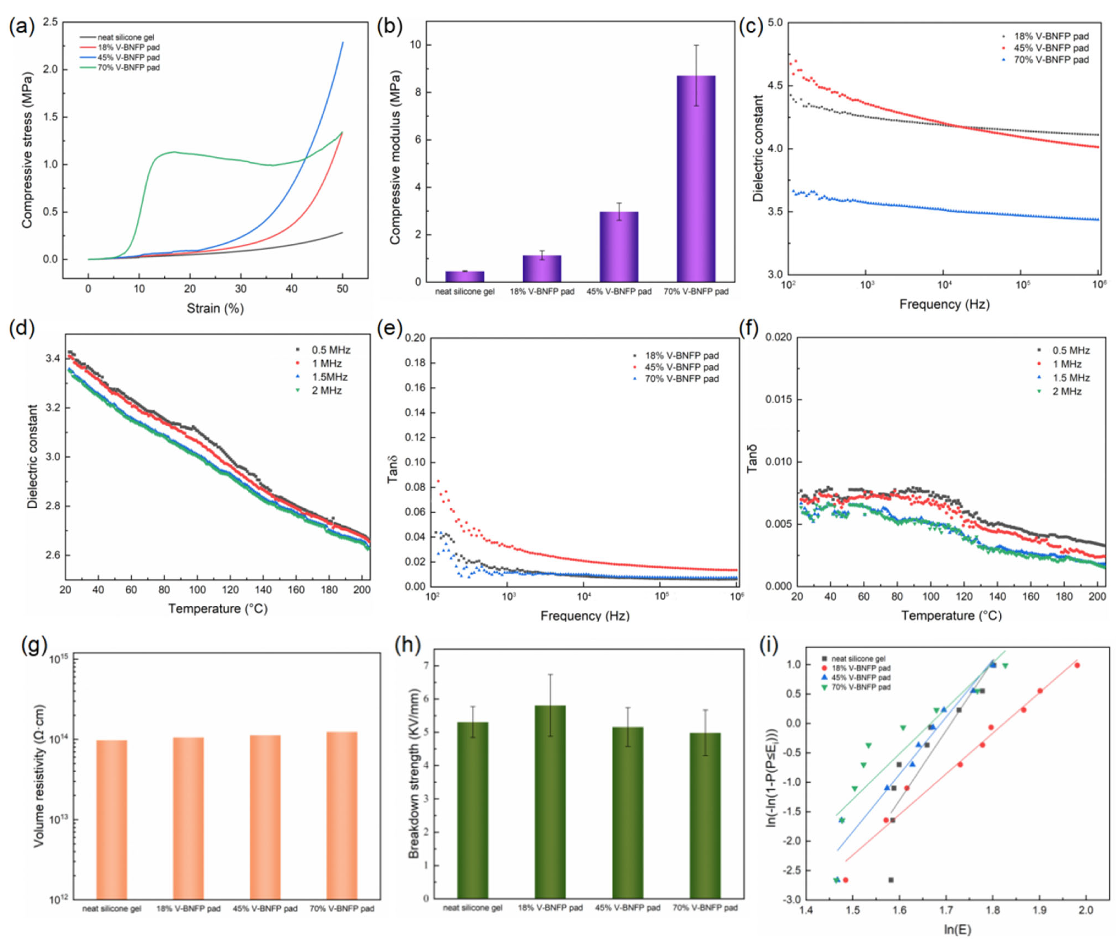
To ensure proper contact as much as possible with both the heat sink and the heat source, TIMs are expected to exhibit good compressibility and stable mechanical properties. Specifically, under moderate packaging pressure (usually <100 psi), TIMs are supposed to deform sufficiently to eliminate air gaps at the contact interfaces [81]. The compressive properties of the thermal pad were characterized, and the corresponding stress-strain curve is presented in Figure 5a. The curve for the 70% V-BNFP thermal pad shows a distinct stress peak, which results from the buckling of its vertically aligned H-BNFP structure under applied pressure. Figure S7 displays multiple stress–strain curves for the 70% V-BNFP thermal pad. The compressive stress of 70% V-BNFP thermal pad was only 1.34 MPa at 50% strain, a value comparable to that of 18% V-BNFP thermal pad. Figure 5b presents the compressive modulus of the materials. The 70% V-BNFP thermal pad has a compressive modulus of 8.62 MPa. Clearly, incorporating H-BNFP into the silicone matrix enhances the compressive modulus, with a more pronounced increase observed at higher filler loading. Regarding TIMs, a stable and low dielectric constant contributes to improving efficiency by ensuring the signal integrity and low dielectric loss (Tanδ) prevents self-heating and reduces energy loss. These characteristics make the TIMs suitable for high-frequency fields such as 5G communication and driver assistance systems. In Figure 5c, the dielectric constant shows a decreasing trend as the frequency increases. At the frequency of 1 MHz, the 70% vol V-BNFP thermal pads have the lowest dielectric constant 3.43. The low dielectric constant of TIMs can be attributed to the orientation polarization of siloxane molecular chains, which increasingly lags the alternating electric field at elevated frequencies, thereby weakening the contribution from dipole relaxation. Additionally, the dielectric constant decreases further with increasing filler content. This reduction may result from the introduction of air gaps within the composite, which lowers the effective dielectric constant due to the near-unity dielectric constant of air [82,83]. It is possible that the rigid H-BNFP fillers may restrict the mobility of polymer segments and polar groups at the interface, thereby suppressing interfacial polarization [84]. Figure 5d presents the temperature-dependent dielectric constant of the 70% V-BNFP thermal pad. It can be observed that the dielectric constant exhibits a decreasing trend with increasing temperature. Figure 5e presents the dielectric loss of the thermal pad. The 70% V-BNFP thermal pad possesses an excellent low dielectric loss of 0.007. Notably, the dielectric loss does not vary linearly with the increase in filler content but rather shows a trend of increasing first and then decreasing. This may be related to the Maxwell-Wagner effect in multi-component dielectrics, as the variation in the interfacial area between the filler and the matrix follows the same trend as that of the dielectric loss [85]. Figure 5f presents the temperature-dependent dielectric loss of the 70% V-BNFP thermal pad. It can be observed that the dielectric loss exhibits only a slight decrease with increasing temperature and remains essentially constant. The temperature-dependent dielectric constant and dielectric loss of neat BN fibers are also provided in Figure S8. The complex permittivity of neat BN fibers exhibits a distinct non-monotonic dependence on temperature, which is characteristic of a thermally activated relaxation process [86]. At low temperatures (below 50 °C), the dielectric constant decreases with increasing temperature. This initial decline is attributed to the delayed response of polarization mechanisms, which relaxation times are too long to follow the alternating electric field at the given measurement frequencies. As temperature further increases, thermal energy facilitates the activation of these polarization species, leading to a subsequent rise in dielectric constant as the relaxation frequency shifts into the measured range. This behavior underscores the high purity of the BN fibers. Insulation is one of the most critical characteristics for thermal pads, which enables them to be used for heat dissipation in various electronic devices. The continuous and dense H-BNFP in this work endows the thermal pad with excellent insulation performance. Figure 5g displays that both the silicone matrix and V-BNFP composite possess an outstanding insulating property as expected, reaching a high electrical volume resistivity value at 1014, 5 times higher orders of magnitude than the insulation standard (109 Ω·cm). Furthermore, the breakdown voltage is also characterized in Figure 5h as an important indicator for evaluating the insulation performance. Clearly, both the silicone matrix and thermal pad exhibit a high breakdown voltage. The addition of the filler to the silicone matrix causes the breakdown voltage of the thermal pad to initially increase and then decrease. This phenomenon may be attributed to the weak interfacial bonding force between V-BNFP and the silicone matrix. Introducing more fillers can create internal defects within the thermal pad, ultimately leading to a reduction in the breakdown voltage. Figure 5i shows the Weibull distribution of the breakdown voltage of the material. It can be observed that at lower H-BNFP contents, the thermal pad exhibits more uniform properties, leading to a better fit of the breakdown voltage data to the expected distribution.
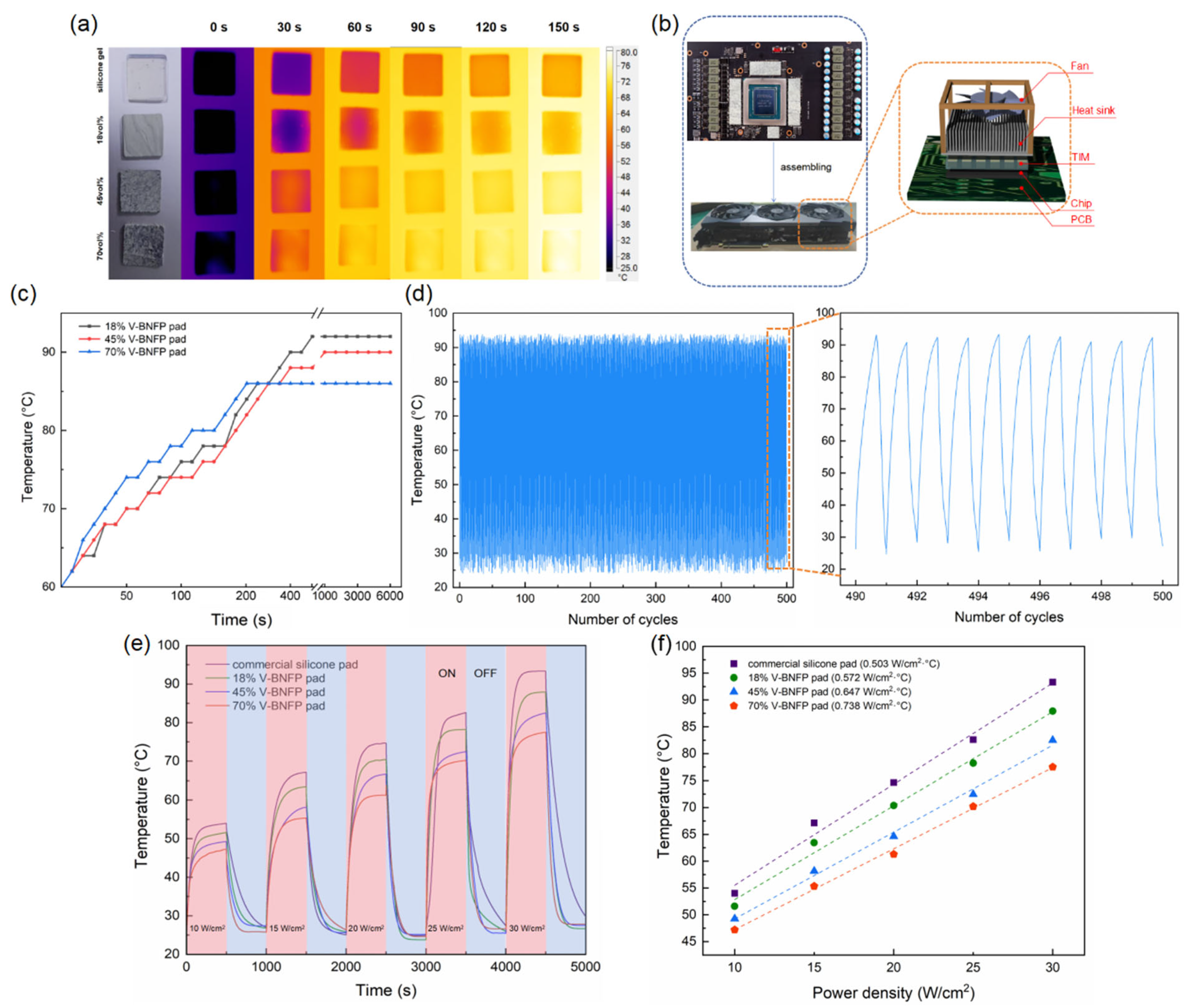
To further investigate the performance of TIMs in practical applications, several experimental devices were designed to simulate or replicate the thermal dissipation behavior in electronic devices. Among these, infrared thermal imaging can intuitively reflect the heat dissipation capacity of thermal pads. Figure 6a illustrates the silicone matrix and V-BNFP thermal pads with the same size (20 × 20 × 2 mm3) heated on a heating platform with temperature set to 100 °C. Infrared thermal imaging clearly reveals that the rate of temperature increase follows the order: 70% > 45% > 18% > neat silicone gel, and 70% V-BNFP thermal pad reaches 77.6 °C after 150 s. The result indicates that increasing the H-BNFP content leads to enhanced thermal conductivity in the thermal pad. Furthermore, the thermal pads are applied to Graphics Processing Unit (GPU). In GPU motherboard, insulating thermal pads are typically placed on the video random access memory (VRAM) chips surrounding the main processing chip. Although it is not the core chip, their thermal performance still has profound impact on the whole GPU system. The schematic diagram of a graphics card test platform is illustrated in Figure 6b. The professional testing software (FurMark, version: 2.10.2.0) and (MSI Afterburner, version: 4.66) were used to operate the GeForce RTX 3080 Ti at its maximum power of approximately 350 W while the fan speed was maintained below 1900 rpm. Figure 6c compares the heat dissipation capabilities of different contents of V-BNFP thermal pad. It is clearly seen that 70% V-BNFP thermal pad is 6 °C lower than 18% V-BNFP thermal pad and have stabilized at 86 °C eventually. The excellent heat dissipation capability of thermal pads enables electronic devices to function within a suitable temperature range, thereby guaranteeing operation security and extending their service life. Heat dissipation stability is one of the crucial properties of TIMs. Thus, the heat source heated the TIMs for 500 s, after which the heat source was turned off to allow for cooling to room temperature, and this process was repeated for 500 cycles. It can be clearly seen in Figure 6d that the steady-state temperature fluctuates within a small range of 90.9 °C to 94.1 °C, which demonstrates the stable heat dissipation of V-BNFP thermal pads. Moreover, to emphasize the superior thermal conductivity of the thermal pads obtained in this work, its thermal performance is compared with that of commercial silicone thermal pads. As illustrated in Figure 6e, the temperature of the heat source (Theat source) was measured for four different types of TIMs under different heating powers. With the heating power increasing, the temperature also gradually rises. Notably, the Theat source of the V-BNFP thermal pad remains consistently lower than that of the commercial silicone thermal pad. The equivalent heat transfer coefficient (EHTC) serves as an indicator of practical thermal conductivity performance, which can be calculated as the reciprocal of the slope of the linear relationship between different heating powers and the corresponding steady-state source temperatures. As shown in Figure 6f, the EHTC values for three V-BNFP thermal pads with different loading and the silicone pad are 0.572, 0.647, 0.738, and 0.503, respectively, suggesting that the cooling efficiency is at most 1.47 times greater than the silicone pad. Therefore, the 70 wt% V-BNFP thermal pads present a promising prospect in practical application for thermal management in various electronic devices.

6. Conclusions

In summary, vertically aligned boron nitride fiber paper-based (V-BNFP) thermal pads were fabricated through a two-step process, as follows: (1) compression of BN fibers into ultra high-density aligned fiber paper, followed by (2) hydraulic pressure molding of stacked sheets. The two-step method significantly improves the vertical orientation of fibers and can prepare thermal pads with higher filler loading (70 wt%), fully utilizing the thermal conductivity advantages of BN fibers. The resulting composite exhibited exceptional thermal conductivity (19.23 W/(m·K)) and low thermal resistance (1.61 cm2·K/W at 2 mm thickness, 50 psi pressure), attributed to continuous thermal conduction pathways formed by BN fibers. This architecture simultaneously achieves superior electrical insulation (volume resistivity > 1014 Ω·cm), high dielectric strength, and mechanical flexibility. Practical thermal performance tests confirmed its superior heat spreading capability compared to conventional silicone-based thermal pads, demonstrating a 23% reduction in operating temperature under 30 W/cm2 heat flux. These characteristics position V-BNFP materials as promising candidates for high-frequency electronics thermal management, while the scalable fabrication process enables cost-effective commercial production.

Supplementary Materials

The following supporting information can be downloaded at: https://www.mdpi.com/article/10.3390/jcs10070351/s1. Figure S1. (a) SEM image of BN fiber diameter. (b) SEM image of BN fiber length. Figure S2. Crystallinity characterization of BN fibers by (a) XRD and (b) Raman. Figure S3. Cross-sectional SEM image of H-BNFP. Figure S4. Schematic diagram of parallel model. Figure S5. Schematic diagram of thermal resistance measurement according to ASTM D5470 standard. Figure S6. Thermal resistance variation of 70% V-BNFP thermal pad under different compressive pressures. Figure S7. Stress and strain curves of the 70% V-BNFP thermal pad. Figure S8. (a) Dielectric constant and (b) dielectric loss of neat BN fibers at various temperatures. Table S1. Thermal diffusivity, density, specific heat capacity, and thermal conductivity of different thermal pads. Table S2. Comparison of thermal conductivity between this work and previously reported TIMs containing high filler loadings of thermally conductive fillers.

Author Contributions

Z.C.: Writing—review & editing, Writing—original draft, Visualization, Validation, Software, Methodology, Investigation, Formal analysis, Data curation, and Conceptualization. Y.C.: Writing—review & editing, Visualization, Validation, and Formal analysis. X.H.: Writing—review & editing, Supervision, Resources, Project administration, Methodology, Data curation, and Conceptualization. S.C.: Writing—review & editing, Supervision, Resources, Project administration, Methodology, Data curation, and Conceptualization. All authors have read and agreed to the published version of the manuscript.

Funding

This work was supported by the National-Natural-Science Foundation of China (grant nos. 11204097 and U1530120) and Guangzhou Science and Technology Plan Project (grant no.201605130850542). And The APC was funded by Sheng Chu.

Data Availability Statement

The data presented in this study are available on request from the corresponding author due to the privacy restrictions.

Acknowledgments

The authors thank Feirongda Technology Co., Ltd. for providing the laboratory space and experimental instruments.

Conflicts of Interest

The authors declare no conflicts of interest.

References

  1. Ding, B.; Zhang, Z.-H.; Gong, L.; Xu, M.-H.; Huang, Z.-Q. A novel thermal management scheme for 3D-IC chips with multi-cores and high power density. Appl. Therm. Eng. 2020, 168, 114832. [Google Scholar] [CrossRef]
  2. Cheng, S.; Guo, X.; Cai, W.; Zhang, Y.; Zhang, X.-A. Enhanced thermal management in electronic devices through control-oriented structures. J. Mater. Chem. A 2024, 12, 8640–8662. [Google Scholar] [CrossRef]
  3. Cui, Y.; Li, M.; Hu, Y. Emerging interface materials for electronics thermal management: Experiments, modeling, and new opportunities. J. Mater. Chem. C 2019, 8, 10568–10586. [Google Scholar] [CrossRef]
  4. Huang, X.; Jiménez, C.J.; Guix, M.; Xufré, C.M.; Tuersun, Y.; Chu, S. Rapidly polymerized multifunctional hydrogel sensor initiated by nanocellulose-stabilized MXene-coated liquid metal for advanced wearable applications. Rare Met. 2025, 44, 6402–6416. [Google Scholar] [CrossRef]
  5. Huang, X.; Tuersun, Y.; Luo, P.; Yang, H.; Chu, S. In-situ reduction of AgNPs on MXene surfaces for synthesis of efficient thermally conductive composites with powerful electromagnetic shielding capabilities. Colloids Surf. A Physicochem. Eng. Asp. 2023, 677, 132444. [Google Scholar] [CrossRef]
  6. Lv, L.; Dai, W.; Li, A.; Lin, C.-T. Graphene-Based Thermal Interface Materials: An Application-Oriented Perspective on Architecture Design. Polymers 2018, 10, 1201. [Google Scholar] [CrossRef]
  7. Dai, W.; Wang, Y.; Li, M.; Chen, L.; Yan, Q.; Yu, J.; Jiang, N.; Lin, C. 2D Materials-Based Thermal Interface Materials: Structure, Properties, and Applications. Adv. Mater. 2024, 36, e2311335. [Google Scholar] [CrossRef]
  8. Xing, W.; Xu, Y.; Song, C.; Deng, T. Recent Advances in Thermal Interface Materials for Thermal Management of High-Power Electronics. Nanomaterials 2022, 12, 3365. [Google Scholar] [CrossRef] [PubMed]
  9. Deng, M.; Xu, Y.; Gao, K.; Zhao, C.; Sheng, N.; Zhu, C.; Rao, Z. A graphene nanoflake-based flexible composite phase change material for enhanced heat dissipation in chip cooling. Appl. Therm. Eng. 2024, 245, 122908. [Google Scholar] [CrossRef]
  10. Zhao, Y.; Zhang, Z.; Cai, C.; Zhou, Z.; Ling, Z.; Fang, X. Vertically aligned carbon fibers-penetrated phase change thermal interface materials with high thermal conductivity for chip heat dissipation. Appl. Therm. Eng. 2023, 230, 120807. [Google Scholar] [CrossRef]
  11. Yuan, P.; Zhang, P.; Liang, T.; Zhai, S. Effects of surface functionalization on thermal and mechanical properties of graphene/polyethylene glycol composite phase change materials. Appl. Surf. Sci. 2019, 485, 402–412. [Google Scholar] [CrossRef]
  12. Li, C.; Wang, W.; Zeng, X.; Liu, C.; Sun, R. Emerging low-density polyethylene/paraffin wax/aluminum composite as a form-stable phase change thermal interface material. Int. J. Miner. Met. Mater. 2023, 30, 772–781. [Google Scholar] [CrossRef]
  13. Ji, H.; Wang, S.; Li, M.; Kim, J. Deep crystallization induced high thermal conductivity of low-temperature sintered Ag nanoparticles. Mater. Lett. 2014, 116, 219–222. [Google Scholar] [CrossRef]
  14. Xie, X.; Pang, Y.; Rao, S.; Zeng, C.; Zhang, L.; Zhang, C.; Guo, S.; Xu, J.; Zeng, X.; Sun, R. Thermal Interface Materials with High Adhesion and Enhanced Thermal Conductivity via Optimization of Polydimethylsiloxane Networks and Aluminum Fillers. ACS Appl. Polym. Mater. 2024, 6, 12765–12773. [Google Scholar] [CrossRef]
  15. Li, F.; Hu, X.; Zhao, Q.; Gao, X.; Feng, Y.; Liu, J. Effect of graphene arrangement on the thermal conductivity of graphene/polymer nanocomposites. Polym. Technol. Mater. 2024, 64, 13–19. [Google Scholar] [CrossRef]
  16. Guo, S.; Wang, M.; Wang, Y.; Chen, J.; Harr, K.; He, L.; Zhang, Y.; Zhang, Y.; Wei, B.; Liu, J. Graphene Film for Multifunctional Graphene-Based Thermal Interface Material with Bidirectional High Thermal Conductivity. Small Struct. 2025, 6, 2400652. [Google Scholar] [CrossRef]
  17. Hayashi, K.; Nakano, T.; Inoue, Y. Enhancing thermal conduction properties of vertically aligned CNT forests by reducing interfacial thermal resistance using an aluminum interlayer. Carbon 2025, 238, 120256. [Google Scholar] [CrossRef]
  18. Wei, S.; Lai, Y.; Zhang, S.; Lin, Q.; Wu, Y.; Hu, X.; Wang, Y.; Dou, Y.; Dong, H.; Song, Y.; et al. Highly thermal conductive and flexible silicone paste filled with alumina and aluminum nitride hybrid fillers. Surf. Interfaces 2025, 72, 107291. [Google Scholar] [CrossRef]
  19. Li, X.; Xu, Q.; Lei, Z.; Chen, Z. Electrostatic flocking assisted aligned boron nitride platelets scaffold for enhancing the through-plane thermal conductivity of flexible thermal interface materials. Ceram. Int. 2023, 49, 22623–22629. [Google Scholar] [CrossRef]
  20. Kim, K.; Ju, H.; Kim, J. Filler orientation of boron nitride composite via external electric field for thermal conductivity enhancement. Ceram. Int. 2016, 42, 8657–8663. [Google Scholar] [CrossRef]
  21. Luo, Y.; He, B.; He, M.; Shan, Y.; Xiao, X.; Peng, R.; He, X.; Jiang, H. Highly thermally conductive of epoxy composites with multi-scale boron nitride interconnected network via magnetic field induced orientation. Compos. Struct. 2025, 374, 119723. [Google Scholar] [CrossRef]
  22. Ghai, V.; Mishra, A.A.; Huang, E.; Ngaloy, R.; Dash, S.P.; Matic, A.; Kádár, R. Halbach Array Induced Magnetic Field Alignment in Boron Nitride Nanocomposites. Adv. Sci. 2024, 12, e2408532. [Google Scholar] [CrossRef]
  23. Wang, J.; Yang, C.; Ma, D.; Zhang, M.; Li, X.; Li, Z.; He, Z.; Liu, L.; Fu, Z.; Yang, J.-Y. Magnetically Oriented 3D-Boron Nitride Nanobars Enable Efficient Heat Dissipation for 3D-Integrated Power Packaging. ACS Appl. Nano Mater. 2023, 6, 18508–18517. [Google Scholar] [CrossRef]
  24. Liu, J.; Li, W.; Guo, Y.; Zhang, H.; Zhang, Z. Improved thermal conductivity of thermoplastic polyurethane via aligned boron nitride platelets assisted by 3D printing. Compos. Part A Appl. Sci. Manuf. 2019, 120, 140–146. [Google Scholar] [CrossRef]
  25. Liu, M.; Chiang, S.-W.; Chu, X.; Li, J.; Gan, L.; He, Y.; Li, B.; Kang, F.; Du, H. Polymer composites with enhanced thermal conductivity via oriented boron nitride and alumina hybrid fillers assisted by 3-D printing. Ceram. Int. 2020, 46, 20810–20818. [Google Scholar] [CrossRef]
  26. Niu, H.; Guo, H.; Kang, L.; Ren, L.; Lv, R.; Bai, S. Vertical Alignment of Anisotropic Fillers Assisted by Expansion Flow in Polymer Composites. Nano-Micro Lett. 2022, 14, 1–15. [Google Scholar] [CrossRef]
  27. Zhan, K.; Chen, Y.; Xiong, Z.; Zhang, Y.; Ding, S.; Zhen, F.; Liu, Z.; Wei, Q.; Liu, M.; Sun, B.; et al. Low thermal contact resistance boron nitride nanosheets composites enabled by interfacial arc-like phonon bridge. Nat. Commun. 2024, 15, 1–12. [Google Scholar] [CrossRef]
  28. Niu, H.; Guo, H.; Kang, L.; Ren, L.; Lv, R.; Liu, L.; Bashir, A.; Bai, S. Highly thermally conductive and soft thermal interface materials based on vertically oriented boron nitride film. Compos. Part B Eng. 2024, 272, 111219. [Google Scholar] [CrossRef]
  29. Yin, Z.; Guo, J.; Jiang, X. Significantly improved thermal conductivity of silicone rubber and aligned boron nitride composites by a novel roll-cutting processing method. Compos. Sci. Technol. 2021, 209, 108794. [Google Scholar] [CrossRef]
  30. Li, N.; Qiu, S.; Du, Q.; An, Y.; Chen, Y.; Li, Y.; Wang, W.; Wu, D.; Wang, X.; Sun, J. Preparation of Highly Thermally Conductive Hexagonal Boron Nitride-Polyvinyl Alcohol/Polydimethylsiloxane Composite Using Combined Freeze-Drying and Spatial Confining Forced Network Assembly Method. Adv. Eng. Mater. 2024, 26, 2400054. [Google Scholar] [CrossRef]
  31. Zhang, T.; Wang, C.; Liu, G.; Yao, C.; Zhang, X.; Zhang, C.; Chi, Q. High thermal conductivity and low dielectric loss of three-dimensional boron nitride nanosheets/epoxy composites. Compos. Commun. 2024, 50, 102007. [Google Scholar] [CrossRef]
  32. Han, G.; Cheng, H.; He, C.; Feng, Y.; Liu, C. Silver nanoparticles bridging segregated hexagonal boron nitride networks for enhancing the thermal conductivity of polystyrene composites. Compos. Commun. 2022, 34, 101267. [Google Scholar] [CrossRef]
  33. Wang, T.; Chi, H.; Zhao, D.; Dong, J.; Li, M.; Jiang, Z.; Zhang, Y. A highly thermally conductive yet electrically insulating boron nitride nanosheets/polyetherimide composite with oriented structure. Compos. Part A Appl. Sci. Manuf. 2024, 188, 108581. [Google Scholar] [CrossRef]
  34. An, L.; An, M.; Yao, B.; Song, J.; Zhang, X.; Ma, W. Unlocking the Trade-off Between Intrinsic and Interfacial Thermal Transport of Boron Nitride Nanosheets by Surface Functionalization for Advanced Thermal Interface Materials. Adv. Mater. 2024, 37, e2412137. [Google Scholar] [CrossRef]
  35. Ravichandran, V.; Chandrashekar, A.; Prabhu, T.N.; Varrla, E. SPI-Modified h-BN Nanosheets-Based Thermal Interface Materials for Thermal Management Applications. ACS Appl. Mater. Interfaces 2024, 16, 34367–34376. [Google Scholar] [CrossRef]
  36. Daneshmehr, S.; Román, F.; Hutchinson, J.M. The surface modification of boron nitride particles. J. Therm. Anal. Calorim. 2019, 143, 151–163. [Google Scholar] [CrossRef]
  37. Tang, B.; Chen, H.; Sun, Y.; Li, M.; Wang, Z.; Yu, H.; Ma, T.; Li, S. Influence from defects of three-dimensional graphene networks on the interface condition between the graphene basal plane and various resins. RSC Adv. 2018, 8, 27811–27817. [Google Scholar] [CrossRef]
  38. Wei, S.; Cao, X.; He, G.; Wu, W.; Tong, Y.; Liu, Y.; Yang, Z. High thermal conductivity in three-dimensional BN/epoxy composites by engineered favorable interfacial adhesion between BN sheets. Ceram. Int. 2023, 50, 12664–12671. [Google Scholar] [CrossRef]
  39. Yan, Q.; Dai, W.; Gao, J.; Tan, X.; Lv, L.; Ying, J.; Lu, X.; Lu, J.; Yao, Y.; Wei, Q.; et al. Ultrahigh-Aspect-Ratio Boron Nitride Nanosheets Leading to Superhigh In-Plane Thermal Conductivity of Foldable Heat Spreader. ACS Nano 2021, 15, 6489–6498. [Google Scholar] [CrossRef] [PubMed]
  40. Chen, L.; Zhao, P.; Xie, H.; Yu, W. Thermal properties of epoxy resin based thermal interfacial materials by filling Ag nanoparticle-decorated graphene nanosheets. Compos. Sci. Technol. 2016, 125, 17–21. [Google Scholar] [CrossRef]
  41. Shi, Z.; Liang, Z.; Huang, Z.; He, A.; Qiao, S.; Tong, A.; Zhang, Y.; Luo, Y.; Wang, M.; He, J.; et al. Revolutionizing fiber materials for space: Multi-scale interface engineering unlocks new aerospace frontiers. Mater. Today 2025, 88, 643–704. [Google Scholar] [CrossRef]
  42. Yang, H.; Tuersun, Y.; Luo, P.; Chen, Y.; Huang, X.; Huang, Q.; Chen, X.; Chu, S. Electrically insulating thermal interface material with ultrahigh thermal conductivity enabled by vertical boron nitride fibers. AIP Adv. 2024, 14, 095301. [Google Scholar] [CrossRef]
  43. Liao, P.; He, H.; Guo, H.; Niu, H.; Kang, L.; Tian, H.; Yao, Z.; Li, Z.; Wang, Y.; Zhang, L.Y.; et al. Highly Thermally Conductive Boron Nitride Fiber. ACS Nano 2025, 19, 16043–16052. [Google Scholar] [CrossRef]
  44. ASTM Standard. Standard Test Method for Thermal Transmission Properties of Thermally Conductive Electrical Insulation Materials; ASTM International: Conshohocken, PA, USA, 2006; p. 36. [Google Scholar]
  45. Tian, Z.; Lu, J.; Feng, X.; Feng, B.; Yin, C.; Lin, Y.; Wang, J. Effects of cross-scale h-BN grains and orientation degree on the mechanical and thermal properties of BN-matrix textured ceramics. Ceram. Int. 2022, 49, 12481–12490. [Google Scholar] [CrossRef]
  46. Kim, H.S.; Jang, J.-U.; Lee, H.; Kim, S.Y.; Kim, S.H.; Kim, J.; Jung, Y.C.; Yang, B.J. Thermal Management in Polymer Composites: A Review of Physical and Structural Parameters. Adv. Eng. Mater. 2018, 20, 1800204. [Google Scholar] [CrossRef]
  47. Tian, C.; Fu, H.; Wang, Z.; Zhang, Z.; Qian, W.; Zhang, H.; Xu, S.; Cao, S.; He, D. Deformable surface design of vertical graphene thermal interface materials for efficient heat dissipation. Cell Rep. Phys. Sci. 2024, 5, 101978. [Google Scholar] [CrossRef]
  48. Qi, X.; Ding, W.; Xu, H.; Wang, Y.; Cheng, Z.; Wang, Z.; Yao, J. Evolution of micro-crystalline features and enhanced mechanical properties of continuous BN fibers. J. Mater. Sci. 2025, 60, 8707–8719. [Google Scholar] [CrossRef]
  49. Du, X.; Yang, W.; Zhu, J.; Fu, L.; Li, D.; Zhou, L. Aligning diamond particles inside BN honeycomb for significantly improving thermal conductivity of epoxy composite. Compos. Sci. Technol. 2022, 222, 109370. [Google Scholar] [CrossRef]
  50. Ye, B.; Li, L.; Dai, K.; Xie, Z.; Zhou, Q.; Dong, Y.; Zheng, Q.; Park, S.; Zhang, Y. Facile preparation of thermally conductive fiber film by self-assembling interconnected boron nitride nanosheets for effective thermal interface materials. Polym. Compos. 2024, 45, 8426–8435. [Google Scholar] [CrossRef]
  51. Hu, J.; Huang, Y.; Zeng, X.; Li, Q.; Ren, L.; Sun, R.; Xu, J.-B.; Wong, C.-P. Polymer composite with enhanced thermal conductivity and mechanical strength through orientation manipulating of BN. Compos. Sci. Technol. 2018, 160, 127–137. [Google Scholar] [CrossRef]
  52. Wan, B.; Li, X.; Zeng, X.; Zha, J.-W. Covalent-assisted construction of “scale-like” boron nitride/polyimide thermal interface materials with high thermal conductivity. Compos. Commun. 2024, 45, 101803. [Google Scholar] [CrossRef]
  53. Ye, N.; Li, J.; Zhang, G.; Lu, Y.; Wang, Z.; Zhang, H.; Lu, Y. Vitrimer-Assisted Construction of Boron Nitride Vertically Aligned Nacre-mimetic Composites for Highly Thermally Conductive Thermal Interface Materials. Chem. Mater. 2023, 35, 5193–5203. [Google Scholar] [CrossRef]
  54. Liu, C.; Duan, X.; Zhang, W.; Huo, Q.; Sui, X.; Liu, Y.; Liang, C. Stable self-crosslinking phase change composites with vertically aligned boron nitride for high thermal conductivity thermal interface materials. Ceram. Int. 2024, 50, 19829–19837. [Google Scholar] [CrossRef]
  55. Han, J.; Du, G.; Gao, W.; Bai, H. An Anisotropically High Thermal Conductive Boron Nitride/Epoxy Composite Based on Nacre-Mimetic 3D Network. Adv. Funct. Mater. 2019, 29, 1900412. [Google Scholar] [CrossRef]
  56. Sun, J.; Huang, F.; Yue, W.; Qin, W.; Shu, D.; Li, J.; Meng, D.; Wang, C. Preparation of Low-Cost and Low-Density Silicone Rubber-Based Thermal Interface Materials by Boron Nitride Oriented Synergistically with Alumina. J. Mater. Eng. Perform. 2024, 34, 12663–12673. [Google Scholar] [CrossRef]
  57. Kong, X.; Chen, Y.; Yang, R.; Wang, Y.; Zhang, Z.; Li, M.; Chen, H.; Li, L.; Gong, P.; Zhang, J.; et al. Large-scale production of boron nitride nanosheets for flexible thermal interface materials with highly thermally conductive and low dielectric constant. Compos. Part B Eng. 2023, 271, 111164. [Google Scholar] [CrossRef]
  58. Lin, H.; Xu, G.; Chen, Z.; Wang, L.; Liu, Z.; Ma, L. Thermally Conductive Polydimethylsiloxane-Based Composite with Vertically Aligned Hexagonal Boron Nitride. Polymers 2024, 16, 3126. [Google Scholar] [CrossRef]
  59. Jia, H.; He, R.; Tian, D.; Yin, H.; Zhang, Z.; An, D. Magnetic-Field-Induced Three-Dimensional Networks to Enhance the Thermal Conductivity for Polydimethylsiloxane-Based Thermal Interface Materials. Polym. Compos. 2025, 46, 17418–17429. [Google Scholar] [CrossRef]
  60. Xue, Y.; Li, X.; Wang, H.; Zhao, F.; Zhang, D.; Chen, Y. Improvement in thermal conductivity of through-plane aligned boron nitride/silicone rubber composites. Mater. Des. 2019, 165, 107580. [Google Scholar] [CrossRef]
  61. Zhang, L.; Qiu, J.; Sakai, E.; Feng, H.; Yamaguchi, H.; Chonan, Y.; Nomura, M. Constructing vertically aligned ternary-filler structures in silicone rubber for anisotropic thermal conductivity. Mater. Today Commun. 2025, 49, 113856. [Google Scholar] [CrossRef]
  62. Yang, K.; Yang, X.; Liu, Z.; Li, K.; Yue, Y.; Zhang, R.; Wang, F.; Shi, X.; Yuan, J.; Liu, N.; et al. Vertically Aligned Boron Nitride Nanosheets Films for Superior Electronic Cooling. ACS Appl. Mater. Interfaces 2023, 15, 28536–28545. [Google Scholar] [CrossRef] [PubMed]
  63. Chen, J.; Huang, X.; Sun, B.; Wang, Y.; Zhu, Y.; Jiang, P. Vertically Aligned and Interconnected Boron Nitride Nanosheets for Advanced Flexible Nanocomposite Thermal Interface Materials. ACS Appl. Mater. Interfaces 2017, 9, 30909–30917. [Google Scholar] [CrossRef] [PubMed]
  64. Zhu, J.; Si, N.; Wu, M.; Zhang, H.; Li, Q.; Huang, B.; Ma, H.; Cai, T.; Wang, Y.; Yu, J.; et al. Soft alumina-based thermal interface materials with enhanced thermal properties enabled by the synergistic effect with hexagonal boron nitride and liquid metal. J. Mater. Sci. Technol. 2025, 244, 60–69. [Google Scholar] [CrossRef]
  65. Lei, C.; Zhang, Y.; Liu, D.; Xu, X.; Wu, K.; Fu, Q. Highly thermo-conductive yet electrically insulating material with perpendicularly engineered assembly of boron nitride nanosheets. Compos. Sci. Technol. 2021, 214, 108995. [Google Scholar] [CrossRef]
  66. Hu, Q.; Bai, X.; Zhang, C.; Zeng, X.; Huang, Z.; Li, J.; Li, J.; Zhang, Y. Oriented BN/Silicone rubber composite thermal interface materials with high out-of-plane thermal conductivity and flexibility. Compos. Part A Appl. Sci. Manuf. 2022, 152, 106681. [Google Scholar] [CrossRef]
  67. Ji, Y.; Li, C.; Wu, H.; Guo, S.; Zhang, F.; Qiu, J. Microchannels-enabled vertical alignment of hexagonal boron nitride in silicone rubber composites to achieve high through-plane thermal conductivity. Compos. Part B Eng. 2024, 290, 111965. [Google Scholar] [CrossRef]
  68. Zhang, L.; Qiu, J.; Sakai, E.; Feng, H.; Zhang, K.; Meng, X.; Zhang, B.; Wu, H.; Guo, S.; Yamaguchi, H.; et al. Highly conductive flexible thermal interface material based on vertically oriented continuous carbon fiber arrays anchored in silicone rubber. Polym. Compos. 2025, 46, 11373–11386. [Google Scholar] [CrossRef]
  69. Hwang, T.; Su, P.; Kim, J. Multifunctional Filler-Engineered PCM Composites With Superior Thermal Conductivity and Leakage Resistance for Advanced Thermal Management. Polym. Compos. 2025, 47, 9352–9361. [Google Scholar] [CrossRef]
  70. Huang, M.; Wang, Z.; Kong, N.; Li, B.; Ye, C.; Jia, K.; Fu, L.; Tian, Y.; Wang, D.; Han, F. Vertically aligned and conformal BN-coated carbon fiber to achieve enhanced thermal conductivity and electrical insulation of a thermal interface material. Chem. Eng. J. 2024, 490, 151621. [Google Scholar] [CrossRef]
  71. Jeon, J.-Y.; Ha, S.-J.; Cha, H.-A.; Kim, J.-H.; Ahn, C.-W.; Choi, J.-J.; Hahn, B.-D.; Bae, S.-H.; Moon, Y.K. Engineering oxide ceramic fillers for thermal interface materials: Enhanced thermal conductivity and thixotropy through hydrophobated MgO/PDMS composite materials. Adv. Compos. Hybrid Mater. 2025, 8, 1–12. [Google Scholar] [CrossRef]
  72. Sanchez, W.A.L.; Li, J.-W.; Chiu, H.-T.; Cheng, C.-C.; Chiou, K.-C.; Lee, T.-M.; Chiu, C.-W. Highly Thermally Conductive Epoxy Composites with AlN/BN Hybrid Filler as Underfill Encapsulation Material for Electronic Packaging. Polymers 2022, 14, 2950. [Google Scholar] [CrossRef]
  73. Jang, S.; Choi, E.J.; Cheon, H.J.; Choi, W.I.; Shin, W.S.; Lim, J.-M. Fabrication of Al2O3/ZnO and Al2O3/Cu Reinforced Silicone Rubber Composite Pads for Thermal Interface Materials. Polymers 2021, 13, 3259. [Google Scholar] [CrossRef]
  74. Matsumoto, N.; Futaba, D.N.; Yamada, T.; Kokubo, K. Enhancing the Thermal Conductivity of CNT/AlN/Silicone Rubber Composites by Using CNTs Directly Grown on AlN to Achieve a Reduced Filler Filling Ratio. Nanomaterials 2024, 14, 528. [Google Scholar] [CrossRef]
  75. Shen, Y.; Li, S.; Qin, B.; Zhang, C.; Li, W.; Wang, B.; Zhu, Z.; Liu, C. Multi-layer graphene nanosheets bridging binary aluminium oxide for the synergistic enhancement of thermal conductivity and electrical insulation of silicone resin composite. Electr. Mater. Appl. 2024, 1, e70000. [Google Scholar] [CrossRef]
  76. Guo, H.; Niu, H.; Zhao, H.; Kang, L.; Ren, Y.; Lv, R.; Ren, L.; Maqbool, M.; Bashir, A.; Bai, S. Highly Anisotropic Thermal Conductivity of Three-Dimensional Printed Boron Nitride-Filled Thermoplastic Polyurethane Composites: Effects of Size, Orientation, Viscosity, and Voids. ACS Appl. Mater. Interfaces 2022, 14, 14568–14578. [Google Scholar] [CrossRef]
  77. Zhang, Z.; Liao, M.; Li, M.; Li, L.; Wei, X.; Kong, X.; Xiong, S.; Xia, J.; Fu, L.; Cai, T.; et al. Enhanced thermal conductivity for polydimethylsiloxane composites with core-shell CFs@SiC filler. Compos. Commun. 2022, 33, 101209. [Google Scholar] [CrossRef]
  78. Kim, W.-J.; An, M.-R.; Park, S.-H. Reduced Anisotropic in Thermal Conductivity of Polymer Composites via Chemically Bonded BN–SiC Hybrid Fillers. Polymers 2025, 17, 2580. [Google Scholar] [CrossRef]
  79. Nayak, S.K.; Mohanty, D.; Sahu, M.R. Thermally conductive and electrically insulated DGEBA-epoxy nano-composite fabri-cated by integrating GO/h-BN and rGO/h-BN hybrid for thermal management applications: A comparative analysis. J. Polym. Eng. 2024, 44, 787–797. [Google Scholar] [CrossRef]
  80. Lee, Y.S.; Yu, J.; Shim, S.E.; Yang, C.-M. Synergistic Effects of Hybrid Carbonaceous Fillers of Carbon Fibers and Reduced Graphene Oxides on Enhanced Heat-Dissipation Capability of Polymer Composites. Polymers 2020, 12, 909. [Google Scholar] [CrossRef]
  81. He, H.; Peng, W.; Liu, J.; Chan, X.Y.; Liu, S.; Lu, L.; Le Ferrand, H. Microstructured BN Composites with Internally Designed High Thermal Conductivity Paths for 3D Electronic Packaging. Adv. Mater. 2022, 34, e2205120. [Google Scholar] [CrossRef]
  82. Ou, Z.; Gao, F.; Zhao, H.; Dang, S.; Zhu, L. Research on the thermal conductivity and dielectric properties of AlN and BN co-filled addition-cure liquid silicone rubber composites. RSC Adv. 2019, 9, 28851–28856. [Google Scholar] [CrossRef]
  83. Xie, Z.; Wu, K.; Liu, D.; Zhang, Q.; Fu, Q. One-step alkyl-modification on boron nitride nanosheets for polypropylene nanocomposites with enhanced thermal conductivity and ultra-low dielectric loss. Compos. Sci. Technol. 2021, 208, 108756. [Google Scholar] [CrossRef]
  84. Zhao, K.; Wei, S.; Wang, M.; Chen, Y. Alkylated modified boron nitride nanosheets/polyimide composite films with advanced thermal conductivity and low dielectric constant. Ceram. Int. 2023, 49, 32577–32587. [Google Scholar] [CrossRef]
  85. Liang, Z.; Pei, Y.; Chen, C.; Jiang, B.; Yao, Y.; Xie, H.; Jiao, M.; Chen, G.; Li, T.; Yang, B.; et al. General, Vertical, Three-Dimensional Printing of Two-Dimensional Materials with Multiscale Alignment. ACS Nano 2019, 13, 12653–12661. [Google Scholar] [CrossRef]
  86. Zhang, T.; Wu, M.-Q.; Zhang, S.-R.; Xiong, J.; Wang, J.-M.; Zhang, D.-H.; He, F.-M.; Li, Z.-P. Permittivity and its temperature dependence in hexagonal structure BN dominated by the local electric field. Chin. Phys. B 2012, 21, 077701. [Google Scholar] [CrossRef]
Figure 1. (a) Schematic diagram of the V-BNFP thermal pad via two-step method; (b) schematic diagram and microscopic image of V-BNFP thermal pad before and after surface cleaning; (c) practical application schematic.
Jcs 10 00351 g001
Figure 2. (a) Optical image of the BN fibers; (b) SEM image of the BN fibers; (c) microscope and SEM image of the H-BNFP and orientation of BN fibers in the H-BNFP; (d) thermogravimetric analysis results of BN fibers, H-BNFP and silicone gel; (e) photograph of the bendable H-BNFP.
Jcs 10 00351 g002
Figure 3. (a) Optical image of the V-BNFP thermal pad; (b) photograph of the bendable V-BNFP thermal pad; (c) microscope and (d) SEM image of the V-BNFP thermal pad; (e) corresponding elemental distribution maps of boron, carbon, nitrogen, and silicon; (f) surface element distribution of the V-BNFP thermal pad; (g) surface roughness images before and (h) after surface cleaning; (i) optical and SEM image of the cross-section of the V-BNFP thermal pad.
Jcs 10 00351 g003
Figure 4. (a) The results of the XRD characterization of the BN fiber, H-BNFP, and surface and cross-section of the V-BNFP thermal pads, and the intensity ratio of peaks (100) and (002), I(002)/I(100), are used as the orientation degree (δ) of the BN platelets. (b) Thermal diffusivity and thermal conductivity of silicone pad, V-BNFP thermal pads with different content (18%, 45%, and 70%) and 70% H-BNFP thermal pad. (c) TCE of V-BNFP thermal pads with different content (18%, 45%, and 70%). (d) Comparison of thermal conductivity of 70% V-BNFP thermal pads with other vertically aligned BN composite [47,48,49,50,51,52,53,54,55,56,57,58,59,60,61,62,63,64,65,66,67,68]. (e) Schematic diagram illustrating the principle of thermal resistance testing according to ASTM D5470 standard. (f) The linear fitting of thermal conductivity and thermal contact resistance of V-BNFP thermal pads with different content (18%, 45%, and 70%). (g) Comparison of thermal resistance between thermal pads with and without silicone grease. (h) Comparison of the thermal resistance of the silicone pad and the V-BNFP thermal pads with different contents (18%, 45%, and 70%) under 50 psi.
Jcs 10 00351 g004
Figure 5. (a) Compressive stress and strain curves of the silicone pad and V-BNFP thermal pads with different contents (18%, 45%, and 70%). (b) Corresponding compression modulus of the pads. (c) Dielectric constant of V-BNFP thermal pads with different contents (18%, 45%, and 70%). (d) Dielectric constant of the 70% V-BNFP thermal pad at various temperatures. (e) Dielectric loss of V-BNFP thermal pads with different contents (18%, 45%, and 70%). (f) Dielectric loss of the 70% V-BNFP thermal pad at various temperatures. (g) volume resistivity of silicone pad and V-BNFP thermal pads with different contents (18%, 45%, and 70%). (h) Breakdown strength of silicone pad and V-BNFP thermal pads with different contents (18%, 45%, and 70%) and (i) the corresponding Weibull distribution of the breakdown strength.
Jcs 10 00351 g005
Figure 6. (a) Infrared thermal images; (b) schematic diagram of the V-BNFP thermal pad application in a GPU system; (c) temperature curves of the VRAM chips during test process; (d) thermal cycling stability of V-BNFP thermal pads; (e) the variation in Theat source over time under different heating powers; (f) EHTC of TIMs.
Jcs 10 00351 g006
Disclaimer/Publisher’s Note: The statements, opinions and data contained in all publications are solely those of the individual author(s) and contributor(s) and not of MDPI and/or the editor(s). MDPI and/or the editor(s) disclaim responsibility for any injury to people or property resulting from any ideas, methods, instructions or products referred to in the content.