Article

Fire-Retardant and Tribological Performance of Painted Ultem 9085 Polymer–Coating Composites Produced via Fused Deposition Modeling


by
Elīna Vīndedze
1,*,
Didzis Dejus
1,
Jānis Jātnieks
1,
Michael Folkert Telkamp
1,
Armands Leitans
2,
Janis Lungevics
2,
Behnam Boobani
3 and
Tatjana Glaskova-Kuzmina
1,3
1
AM Craft, Braslas 22D, LV-1035 Riga, Latvia
2
Mechanical Engineering, Aerospace Technologies and Transport Institute, Riga Technical University, Kipsalas 6b, LV-1048 Riga, Latvia
3
Institute for Mechanics of Materials, University of Latvia, Jelgavas 3, LV-1004 Riga, Latvia
*
Author to whom correspondence should be addressed.
J. Compos. Sci. 2026, 10(6), 295; https://doi.org/10.3390/jcs10060295
Submission received: 27 April 2026 / Revised: 21 May 2026 / Accepted: 25 May 2026 / Published: 29 May 2026
(This article belongs to the Special Issue Additive Manufacturing of Composites and Nanocomposites, 2nd Edition)

Abstract

Materials applied in interior and non-structural aircraft components are required to satisfy rigorous safety and performance criteria, especially with respect to flame retardancy and wear resistance. Ultem 9085, a high-performance polyetherimide thermoplastic, is extensively used in aerospace applications owing to its advantageous strength-to-weight ratio and compliance with flame, smoke, and toxicity (FST) requirements. Nevertheless, the application of surface coatings, including paints, may modify their fire-retardant and tribological performance, with potential implications for service behavior and regulatory compliance. This work provides new insight into the behavior of painted Ultem 9085 components under fire exposure and frictional loading, addressing the critical need to determine whether surface finishing affects the material’s inherent performance advantages. Thus, the effects of different paint coatings on the fire-retardant and tribological properties of Ultem 9085 are investigated. Test specimens were manufactured using a Stratasys F900 system with 100% infill density and geometries adapted for standard vertical burn and heat release tests. Fire performance testing, including vertical burn, smoke and toxicity, and heat release rate, was performed in accordance with CS/FAR 25 Appendix F and AITM 3-0005 requirements. Tribological behavior was assessed using a ball-on-flat tribometer under dry-sliding conditions, while surface texture was analyzed using 3D profilometry. Seven polymer–coating composites were examined. It was experimentally confirmed that all coatings reduced vertical burn length but increased peak heat release rate and smoke density relative to unmodified Ultem 9085. Tribological results varied significantly, highlighting the critical role of paint selection in achieving optimal fire safety and wear resistance.

1. Introduction

Materials used for interior and non-structural components in the aviation industry must comply with stringent safety, durability, and regulatory requirements. Typical cabin-interior materials include phenolic-glass-fiber honeycomb panels for sidewalls, ceilings, partitions, galleys, and overhead bins; flame-retardant polycarbonate sheets or copolymers for light diffusers, instrument panels, and seating components; polyphenylsulfone (PPSU) sheets for transparent or thermoformed cabin parts; and high-performance thermoplastics such as polyetherimide (PEI) for additively manufactured brackets, ducts, covers, and replacement parts [1,2,3,4,5,6,7,8]. These materials are selected primarily for their FST performance, low mass, processability, and durability. For example, phenolic fiberglass panels provide excellent flame resistance, low heat release, and low smoke generation, but phenolic systems are typically more brittle and more difficult to process than thermoplastics [9,10]. Flame-retardant polycarbonate offers high impact strength, transparency, and good thermoformability, and some aerospace grades report heat release performances below 55 kW m−2 for peak heat release and below 55 kW min m−2 for total heat release; however, polycarbonate generally requires flame-retardant modification and surface protection to meet demanding cabin-interior requirements [11,12]. PPSU grades developed for aircraft interiors provide low heat release, low smoke generation, and low toxic gas emissions, but their use is usually limited to sheet-based or molded components rather than geometrically complex, tooling-free production [13]. These examples illustrate that no single material simultaneously maximizes FST performance, mechanical performance, surface durability, design freedom, and processing simplicity.
The increasing adoption of additive manufacturing (AM) technologies in aerospace has further intensified the need to understand the printing route, build orientation, raster architecture, surface roughness, and post-processing steps that influence material performance under service-relevant conditions [1,2,3,14]. In contrast to conventional sheet thermoforming or injection molding, fused deposition modeling (FDM) enables low-volume, lightweight, and geometrically complex parts to be manufactured without dedicated tooling. This is attractive for aircraft-interior spare parts and customized non-structural components, where weight reduction, supply-chain flexibility, and part consolidation are important [7,8]. However, FDM polymers often exhibit anisotropic mechanical properties, interlayer interfaces, and relatively rough surfaces, which can influence both fire response and tribological behavior.
Ultem 9085, a high-performance PEI thermoplastic, has emerged as one of the most widely used polymeric materials for aerospace AM applications, particularly in FDM. Its popularity stems from its favorable strength-to-weight ratio; high thermal and chemical resistance; and, critically, its inherent compliance with FST requirements mandated by CS/FAR 25 regulations [4,5,6]. PEI has found extensive use in aircraft and transportation interior panels, seat-folding tables, class dividers, and other non-structural components produced via FDM [7,8].
Despite its intrinsic fire-safe characteristics, components manufactured from Ultem 9085 often require surface finishing for functional, aesthetic, or protective purposes. Aircraft cabin parts are often painted or coated to match interior color schemes, improve cleanability, protect against ultraviolet exposure or moisture, reduce surface roughness, and increase wear resistance. From a materials perspective, the introduction of a coating transforms the system into a polymer–coating composite, where overall performance is governed not only by the bulk polymer but also by coating chemistry, coating thickness, pigment and additive content, surface preparation, and interfacial adhesion [15,16]. While coatings can enhance specific surface-related properties, they may also significantly alter fire behavior and tribological performance.
Recent studies have shown that surface treatments and coatings can have beneficial or detrimental effects on fire behavior. Barrier-forming coatings may delay ignition, reduce heat release, and restrict oxygen or volatile-fuel transport, whereas organic coating systems with combustible binders can increase smoke density, toxic gas evolution, or heat release if they decompose before the substrate [17,18,19,20].
In parallel, tribological performance is a critical consideration for many interior aerospace components subjected to repeated contact, vibration, or sliding motion. Wear resistance and friction behavior directly influence component lifespan, maintenance intervals, and the risk of debris generation in enclosed cabin environments. Previous research has demonstrated that surface coatings can either reduce friction and wear through lubrication effects or lead to premature failure due to poor adhesion or brittle behavior under load [21,22]. For additively manufactured polymers, surface roughness, layer orientation, and anisotropy further complicate tribological performance, making systematic evaluation essential [14]. Finally, coating 3D-printed objects not only protects them from environmental factors but also enhances their visual appearance [23].
Although Ultem 9085 has been extensively studied for its mechanical properties and baseline fire performance, there is a notable lack of comprehensive investigations into the combined effects of paint coatings on fire-retardant and tribological behavior, particularly for FDM-manufactured components. Existing studies often focus on either fire performance or wear behavior, and data on painted Ultem 9085 systems remain scarce [24,25]. This knowledge gap is especially relevant for aerospace qualification, where post-processing steps must not compromise regulatory compliance.
Therefore, the novelty of this work is in the evaluation of painted FDM-manufactured Ultem 9085 as a complete polymer–coating system under fire exposure and frictional loading, thereby determining whether surface finishing preserves, improves, or degrades the material advantages that make Ultem 9085 attractive for aircraft-interior applications. The present study aims to evaluate the effects of several aerospace-relevant paint coatings on the fire-retardant and tribological properties of FDM-manufactured Ultem 9085. By combining standardized fire testing with tribological analysis, this work seeks to guide the selection of coating systems that balance safety, durability, and functional performance in demanding aerospace applications.

2. Materials and Methods

2.1. Material and Sample Manufacturing

The material used was Ultem 9085 supplied by Stratasys (Eden Prairie, MN, USA), a PEI widely used in FDM. The filament was supplied in a canister, vacuum-sealed in a protective bag with desiccant packs, and stored at 13–24 °C and <60% relative humidity, as per the supplier’s instructions. For the manufacturing of the raw samples, the Stratasys F900 (Eden Prairie, MN, USA) machine was used. Samples were printed with 100% infill density, flatwise, with a thickness of 1 mm, and the dimensions were adjusted to meet the requirements for the vertical burn 75 mm × 305 mm, heat release 150 mm × 150 mm, and smoke and toxicity 75 mm × 75 mm tests according to AITM 3-0005 and CS/FAR 25 Appendix F, Parts I, IV, and V, of the aviation standard. The printing parameters are provided in Table 1.
Waterborne and solvent-borne two-component polyurethane coatings supplied by Mankiewicz (Hamburg, Germany) were applied with a spray gun in accordance with the manufacturer’s application instructions, with controlled thickness. The same filler Alexit PrimeFill 500 (Hamburg, Germany) was used for all test specimens, applied in two layers. As a result, seven different polymer–coating composites were manufactured. The processing details are provided in Table 2.

2.2. Testing Methods

2.2.1. Fire Retardant Testing

The vertical burn, smoke, toxicity, and heat release rate tests were carried out at Aeroworks Europe (Middenmeer, The Netherlands) in accordance with AITM 3-0005 and CS/FAR 25 Appendix F, Parts I, IV, and V, of the aviation standards. Before testing, all specimens were conditioned for at least 24 h at 20 °C and 50% relative humidity to ensure consistent test conditions. At least 3 specimens were tested per test group.
The 60 s vertical burn tests (V60) were conducted using HVFAA equipment (Atlas Material Testing Technology LLC, Mount Prospect, IL, USA) to assess flame resistance in accordance with FAR 25.853 [26] and FAR 25.855 [27]. The ignition time was fixed at 60 s. Flame time was defined as the time the specimen continued to burn after burner removal, excluding glowing without flame. Drip flame time was defined as the burning time of any flaming drips after falling from the specimen; if no dripping occurred, it was recorded as 0 s. Burn length was measured as the distance from the original specimen edge to the furthest point of combustion damage, excluding soot, staining, warping, discoloration, and heat-induced shrinkage. The V60 test setup is shown in Figure 1a. The acceptance criteria required average values of ≤15 s for flame time, ≤3 s for drip flame time, and ≤150 mm for burn length. The testing procedure is similar to that previously reported for PEI [28].
The fire-induced smoke and toxic gas emission behavior of the investigated polymer–coating composites was characterized in two complementary steps. First, the maximum specific optical smoke density (Max Ds) was measured in the NBS smoke chamber ME1100-1 (Marlin Engineering, Bellingham, WA, USA) according to EASA CS 25.853 Appendix F Part V [29], which sets a regulatory limit of Ds < 200 at 4 min. Second, a quantitative gas speciation analysis was performed on the combustion effluents for the six toxic species most commonly controlled in aerospace qualification—hydrogen cyanide (HCN), carbon monoxide (CO), nitrous oxides (NOx), sulfur dioxide (SO2), hydrogen fluoride (HF), and hydrogen chloride (HCl)—with results compared against the thresholds defined in Airbus ABD 0031 and Boeing D6-51377, which are the two industry standard toxicity specifications applied to cabin interior parts. Both tests were performed under a heat flux of 2.5 W/cm2 on the uncoated Ultem 9085 reference and on all seven painted composites under identical conditions. The setup for the smoke and toxicity testing is provided in Figure 1b.
Heat release rate tests were performed in accordance with CS/FAR 25.853, Appendix F, Part IV [30], using the ME1200-1 (Marling Engineering, Bellingham, WA, USA) calorimeter to measure peak heat release rate and total heat release during the first 2 min of exposure. Compliance with the 65/65 criterion required average peak heat release rates of no more than 65 kW/m2 and 2 min total heat release of no more than 65 kW·min/m2.

2.2.2. Tribological Testing and 3D Texture Measurements

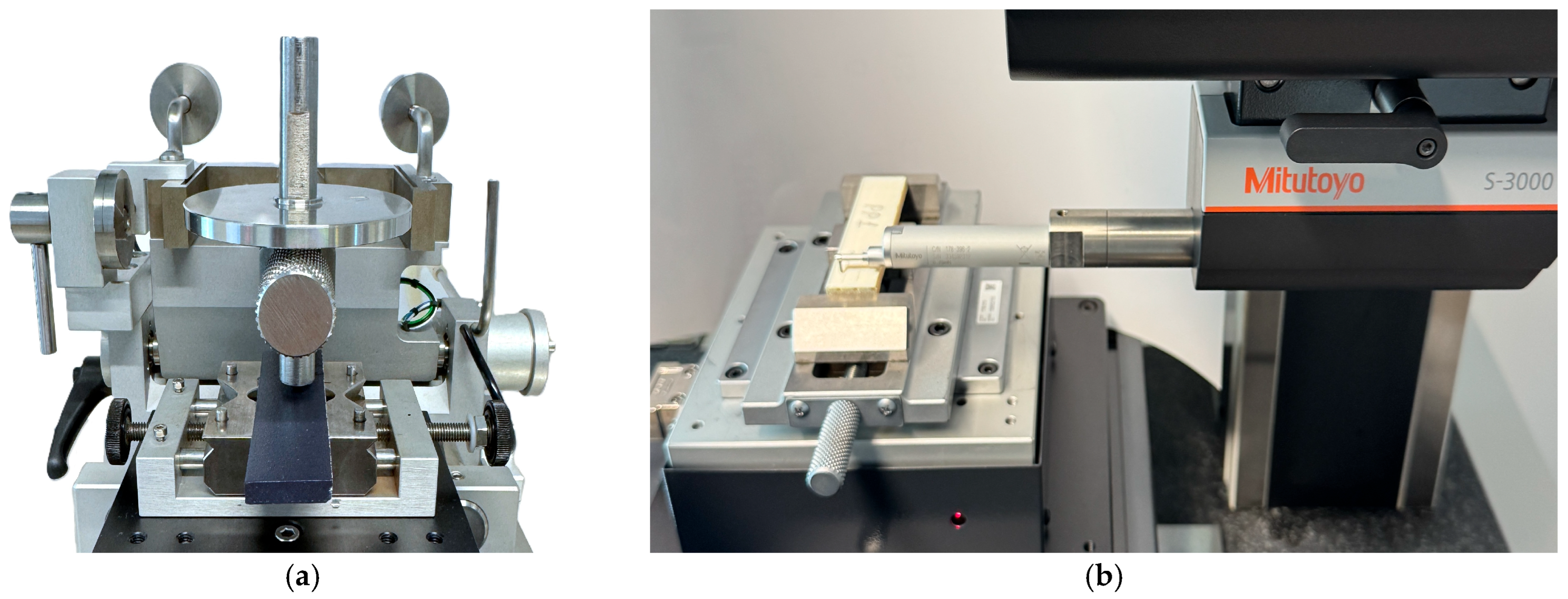
Sliding friction tests were performed on painted Ultem 9085 samples using a ball-on-disc tribometer (TRB 3, CSM Instruments, Peseux, Switzerland) under dry friction conditions, according to ASTM G133-22. A photo of the painted Ultem 9085 sample during the sliding friction test is provided in Figure 2a. Three specimens were tested for each material type. All tests were performed in a linear reciprocating mode that ensures surface asperity bending forward and back, which ensures higher wear intensity. The test cycle stroke amplitude was set to 10 mm, the linear sliding speed to 0.13 m/s, and the normal load to 3 N. The friction force acquisition rate was 50 Hz. One full friction cycle was carried out in 1 s. Each sample was tested for 1000 and 3000 cycles to mimic medium and high wear conditions. A normal load of 3 N was selected experimentally by conducting preliminary tests. Such a load value provided the optimal conditions to indicate differences between widely different specimens. Tribology results were analyzed by maximum peak values (Max CoF) and mean CoF at the test plateau region, including also the running-in part of the full experiment. The sample surface 3D texture was measured with a 3D profilometer AVANT FTA-S4 S3000-D (Mitutoyo, Kawasaki, Japan) before and after tribological tests to observe the wear impact on the surfaces. An area of 10 mm × 3 mm was measured for each sample with a point density of 1 µm × 15 µm, respectively. Z-axis resolution was set to 10 nm. All 3D measurements were post-processed in MCubeMap Ultimate V10 software (Mitutoyo, Kawasaki, Japan). The photo of the 3D profilometer with the raw Ultem 9085 sample is shown in Figure 2b.

3. Results and Discussion

3.1. Flame Retardant Properties

3.1.1. Vertical Burn Test

The 60 s vertical burn test is particularly important for aerospace interior applications because it evaluates the ability of a material system to resist sustained upward flame propagation under severe exposure conditions [31,32]. In a vertical configuration, buoyancy-driven heat and flame spread can intensify burning; therefore, materials used in cabin interiors must self-extinguish rapidly, limit burn length, and avoid flaming drips. For painted FDM Ultem 9085, this test is also essential to confirm that the coating system does not compromise the inherent flame-retardant performance of the PEI substrate or its compliance with CS/FAR 25.853 Appendix F requirements.
The mean vertical burn length and standard deviation obtained for uncoated Ultem 9085 (RAW) and the seven painted polymer–coating composites are presented in Table 3, together with the relative change with respect to the unpainted baseline. The regulatory acceptance criterion specifies that the average burn length shall not exceed 150 mm after removal of the ignition source. Flame spread resistance is a primary requirement for cabin interior parts, and any surface treatment applied to a certified base polymer must preserve or improve this characteristic.
All specimens complied with the 150 mm regulatory threshold, with group-level means ranging from 55.67 ± 2.08 mm (PP5) to 95.67 ± 6.03 mm (RAW). Contrary to what might be expected from the introduction of additional combustible material at the specimen surface, every painted system produced a burn length shorter than that of the uncoated Ultem 9085 substrate. The relative reduction ranged from −4.53% for PP7 (Alexit Suede-Coating 404-74) to −41.81% for PP5 (Alexit 404 system with 404-15 clear topcoat), indicating that the tested coatings actively reduced the upward flame front rather than propagating it.
This behavior can be explained by the condensed-phase protective action commonly reported for flame-retardant polymer coatings. During fire exposure, coating layers may thermally decompose and generate a carbonaceous surface residue that acts as a thermal barrier and restricts volatile-fuel transport from the underlying polymer to the flame zone. Such char-forming behavior is widely recognized as one of the main mechanisms by which flame-retardant coatings delay ignition, suppress flame spread, and reduce heat feedback to the substrate [33,34,35,36]. It is also consistent with previous work on Ultem 9085, where FDM-processed specimens satisfied CS/FAR 25.853 requirements and where burn length was linked to the effective mass and geometry of the printed polymer system [37].
The most pronounced reduction observed for PP5 can be attributed to the multilayer architecture of this coating system, comprising a Primefill 500 primer, a 404-12 base coat, a 404-54 intermediate layer, and a 404-15 clear topcoat. The cumulative thickness of four stacked organic layers is expected to yield a thicker, more cohesive carbonaceous residue during pyrolysis, providing the most effective thermal shielding of the underlying Ultem 9085 among the tested configurations. In contrast, systems containing a single color coat over the primer (PP7 and PP8) exhibited the smallest improvement in flame spread resistance, suggesting that thinner coating stacks provide a less substantial barrier and that the flame front advances more similarly to that on the raw polymer. The low within-group standard deviations obtained for most groups (≤3.21 mm for PP4, PP5, PP7, PP8, and PP9) confirm the repeatability of the V60 measurement and the uniformity of film application achieved under controlled workshop conditions. Overall, the flammability data indicate that selecting an FST-qualified paint system does not degrade Ultem 9085′s inherent V60 performance and, in several cases, provides a measurable margin of safety below the regulatory limit.

3.1.2. Smoke Density and Toxicity

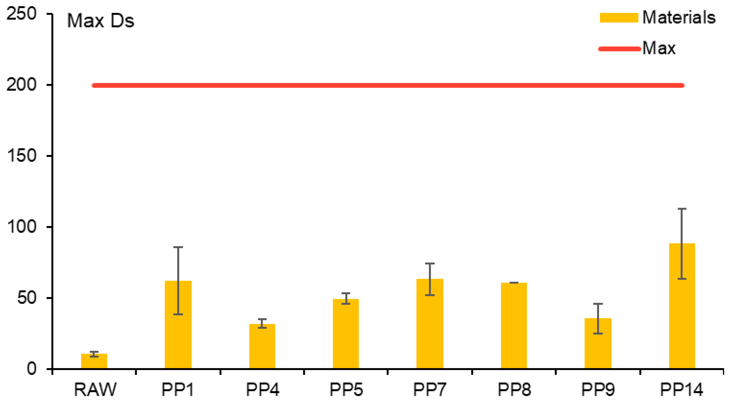
Smoke density measurements revealed pronounced differences among the coating systems. Results are presented in Figure 3. All coating systems increased smoke generation relative to RAW. The highest smoke density was observed for PP14 (88.3 ± 24.7), followed by PP7 (63.3 ± 11.1), PP1 (62.0 ± 23.6), and PP8 (61.0 ± 0.0). Despite this increase, all values remained significantly below the aerospace acceptance threshold of Ds < 200, confirming continued compliance. The increase in smoke density after painting is consistent with the presence of additional organic binder phases, pigments, and additives introduced by the coatings. During combustion, these constituents may undergo incomplete oxidation, generating soot particles and condensed phase smoke products. This explanation is consistent with the broader fire-toxicity literature, which shows that incomplete combustion increases the formation of smoke and toxic products such as CO, HCN, hydrocarbons, oxygenated organics, and soot particulates [38]. It is also consistent with aircraft-interior fire studies showing that smoke density and toxic gas generation are essential descriptors of material fire performance in confined cabin-like environments [39].
Interestingly, coatings that improved flame spread resistance did not necessarily improve smoke behavior. For example, PP5 reduced burn length substantially but still produced elevated smoke density (49.7 ± 3.8). This confirms that flame spread resistance and smoke evolution are governed by different combustion mechanisms. From a material selection perspective, this distinction is highly relevant for aerospace interior applications, where low smoke emission is critical because smoke can obscure escape-path markings and exits, reducing passenger visibility during emergency evacuation [40].
The average concentrations and standard deviations of the six regulated toxic species, measured for both the uncoated reference and the seven painted composites, are presented in Table 4. The Airbus ABD 0031 and Boeing D6-51377 threshold values are reproduced at the bottom of the table for reference.
All eight materials satisfied every individual toxicity criterion of both specifications and the most demanding single value recorded across the dataset—HCl for PP4 corresponded to 44.4% of the ABD 0031 limit of 150 ppm, leaving a safety factor greater than two against the stricter of the two industry standards.
Inspection of the RAW specimens provides a physically meaningful baseline against which the coating-related contribution can be isolated. Even in the absence of any paint, Ultem 9085 produced measurable amounts of CO (74.67 ± 17.93 ppm), NOx (3.17 ± 0.47 ppm), SO2 (1.67 ± 0.58 ppm), and HCl (3.33 ± 0.58 ppm), together with a very low but non-zero HCN signal (0.50 ppm across all three replicates). All six RAW values remain below 8% of their respective regulatory thresholds, confirming that the substrate itself poses no toxicity hazard and justifying its use as the reference polymer for cabin applications. HF was not detected in any specimen (HF = 0 ppm across all 24 replicates), consistent with the absence of fluorinated constituents in both the Ultem 9085 polyetherimide matrix and the tested paint systems, and indicating that HF is not a hazard of concern for this material class. These results are consistent with previous reports that FDM-printed Ultem 9085 maintains low smoke and toxicity levels and complies with aviation safety requirements [6,37].
CO dominated the absolute emission profile across all materials tested, but its increase above the RAW baseline was modest, ranging from 1.2× (PP9) to 2.0× (PP14). This indicates that CO is primarily associated with decomposition of the polymeric substrate and the organic fraction of the coating system. The highest CO value, measured for PP14, reached only 14.6% of the ABD 0031 limit. This result is relevant because CO is widely recognized as a major toxicant in fire effluents, while heat release remains a key driver of fire growth and overall hazard development [38,41].
HCN and HCl emissions exhibited the opposite pattern and were more strongly coating-dependent. RAW Ultem 9085 produced only 0.50 ppm HCN and 3.33 ppm HCl, while painted systems reached up to 5.00 ppm HCN (PP4) and 66.67 ppm HCl (PP4), corresponding to ratios of 10× and 20× with respect to the unmodified substrate. These increments are the clearest chemical fingerprints of the paint layer in the combustion effluent. Despite the large relative increase, all painted systems remain below 3.3% of the HCN limit and 45% of the HCl limit, confirming that coating-induced increases in these two species do not compromise regulatory compliance.
NOx and SO2 emissions showed a more subtle behavior. Across most paint systems, the NOx concentration is approximately 1.3–1.6× the RAW baseline, and the SO2 level is indistinguishable from RAW, indicating that the majority of the tested coatings contribute negligibly to sulfur chemistry and only modestly to nitrogen oxidation.
Overall, the combined smoke density and gas speciation results demonstrate that all seven investigated paint systems preserve the low-toxicity gas-emission characteristic of Ultem 9085 and satisfy both the Airbus ABD 0031 and the Boeing D6-51377 toxicity specifications. The toxicity response, therefore, does not constitute a limiting factor for the qualification of any of the tested polymer–coating composites for cabin interior applications. However, the increase in smoke density after painting confirms that coating selection cannot be based only on vertical burn length.

3.1.3. Heat Release Rate

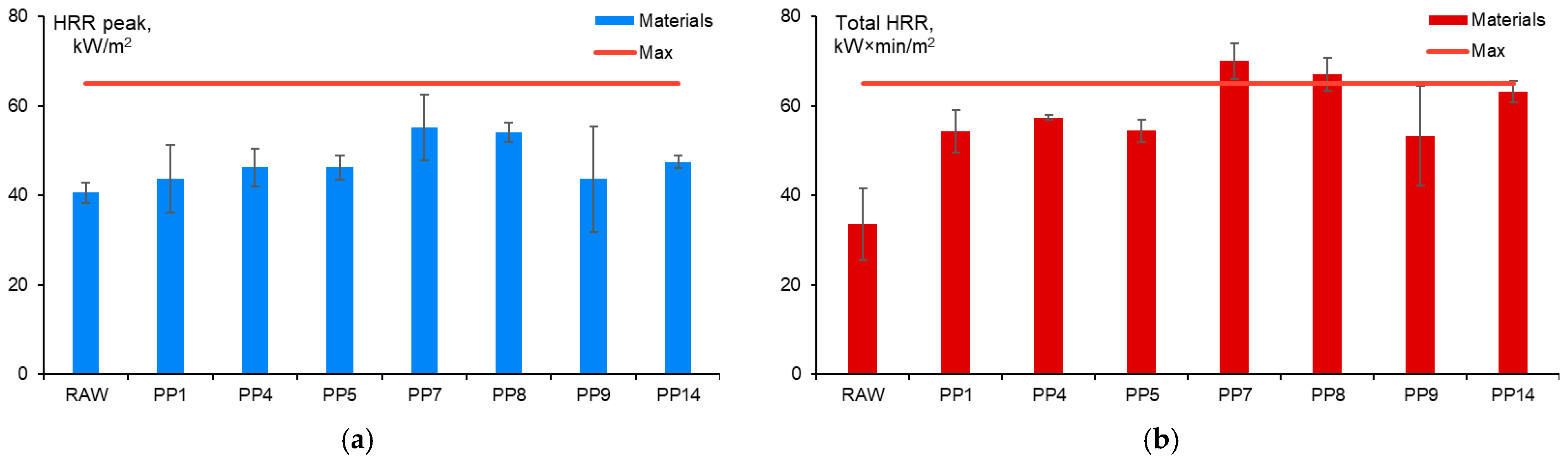
Regarding the peak heat release rate, all groups complied with the 65 kW/m2 limit. The lowest mean peak was obtained for the uncoated polymer (40.60 ± 2.23 kW/m2), while the highest was recorded for PP7 (55.17 ± 7.40 kW/m2) and PP8 (54.07 ± 2.14 kW/m2). Results for peak heat release (pHRR) together with total heat release (tHRR) are presented in Figure 4.
The observed increase relative to RAW ranged between +7.5% (PP9) and +35.9% (PP7), reflecting the additional combustible loading introduced by the coating layer. Even so, all painted systems retained approximately 15–25% compliance margins below the pHRR threshold. It revealed that peak heat release alone was not the limiting parameter for the investigated painted Ultem 9085 systems.
The HRR, integrated over the first two minutes, produced a markedly different picture. Two coating systems, PP7 (Alexit Suede-Coating 404-74) and PP8 (Alexit Microeffekt 404-75), exceeded the 65 kW·min/m2 regulatory limit with group level means of 70.03 ± 4.03 kW·min/m2 and 67.00 ± 3.67 kW·min/m2, respectively, and must therefore be regarded as non-compliant for cabin interior applications in their tested configuration or their use in cabin interior applications is limited to small area components only. PP14 (Isovolta AIRDEC-F3) also approached the limit very closely at 63.13 ± 2.40 kW·min/m2, leaving less than a 3% design margin; under production variability, this group would be considered marginal and would typically require either tightening process control or an additional safety-factor demonstration during part qualification. All remaining systems—PP1, PP4, PP5, and PP9—exhibited total HRR values between 53.30 and 57.40 kW·min/m2, corresponding to 12–18% compliance margins.
The importance of these results is supported by the fire-safety literature, where heat release rate is considered one of the most important variables governing fire hazard because it controls fire growth, heat feedback, and the development of untenable conditions [19,41]. In the present work, the distinction between a single maximum value and total heat release is critical, since while all painted systems passed the pHRR criterion, two failed the tHRR criterion.
The time-to-peak analysis provided additional insight into the combustion kinetics of each system. Results are presented in Table 5. Longer times to peak are generally associated with more progressive ignition and delayed heat release, which are beneficial for both escape-time considerations and avoiding localized flashover. In the present dataset, PP9 and PP5 exhibited the latest time to peak (114.0 ± 15.1 s and 103.3 ± 40.3 s, respectively), consistent with the thick multilayer architecture of these coating stacks, which act as thermal barriers that delay substrate pyrolysis. Conversely, PP7 and PP8 reached peak heat release extremely rapidly (15.7 ± 2.1 s and 18.7 ± 1.5 s), indicating that their thin, solvent-borne topcoats ignite almost immediately upon exposure to the radiant flux and release their heat content before any significant char layer can develop. This early peak behavior is fully consistent with the higher tHRR values and the shorter burn-through protection observed for these two coatings.
When the heat release outcome is cross-referenced with the smoke and flammability results, a coherent pattern emerges: paint systems with a rapid, intense combustion signature (PP7, PP8, and PP14) also tend to produce higher smoke densities, while systems with delayed, more progressive combustion (PP5 and PP9) provide the most favorable overall FST balance. This supports the conclusion that flame spread, smoke density, toxicity, and heat release must be evaluated as complementary rather than interchangeable parameters and their interrelation was quantified by the Kendall’s tau correlation analysis reported in Section 3.2.
From a certification perspective, the heat release test is therefore the most selective of the three FST criteria examined in this study. This is consistent with aircraft-interior flammability requirements, where the Ohio State University (OSU) (Columbus, OH, USA) heat release test defines separate pass/fail limits for both peak heat release rate and the two-minute total heat release: pHRR ≤ 65 kW/m2 and tHRR ≤ 65 kW·min/m2 [42]. Even though all tested paint systems preserve the V60 and smoke compliance of the Ultem 9085 substrate, not all of them preserve the 65/65 heat release compliance. This distinction is important because heat release rate is widely regarded as one of the most important indicators of fire hazard, and the full HRR curve, including total heat release, ignition behavior, and residue formation, provides more meaningful information than pass/fail flame spread data alone [41]. Accordingly, the decisive parameter for paint selection on certified cabin interior parts must be total heat release, with particular attention to thin, single-layer solvent-borne topcoats, which showed the highest risk of non-compliance in the present dataset, since previous coating studies have shown that surface layers can either reduce heat release through char/barrier formation or increase fire loading depending on coating chemistry, thickness, and degradation behavior [43].

3.2. Statistical Analysis

Data were analyzed using Microsoft Excel 365 and JASP v0.18.3. Normality was assessed using the Shapiro–Wilk test. As the data were not normally distributed, correlation analysis was performed using Kendall’s tau (τ). Results are reported as mean (M), standard deviation (SD), and p-value, with statistical significance set at p < 0.05. Descriptive statistics for the measured fire-performance variables across all samples are presented in Table 6. The total heat was 56.63 ± 11.74 kW · min/m2, while the maximum smoke density was 50.33 ± 25.37. The vertical burn length was 79.45 ± 12.56 mm. In addition, the heat release rate peak was 47.12 ± 6.96 kW∙min/m2, and the time to peak was 59.91 ± 47.65 s. Overall, the results indicate substantial variability in smoke density and time to peak, as reflected by their relatively large standard deviations, whereas peak heat release rate exhibited comparatively lower variability.
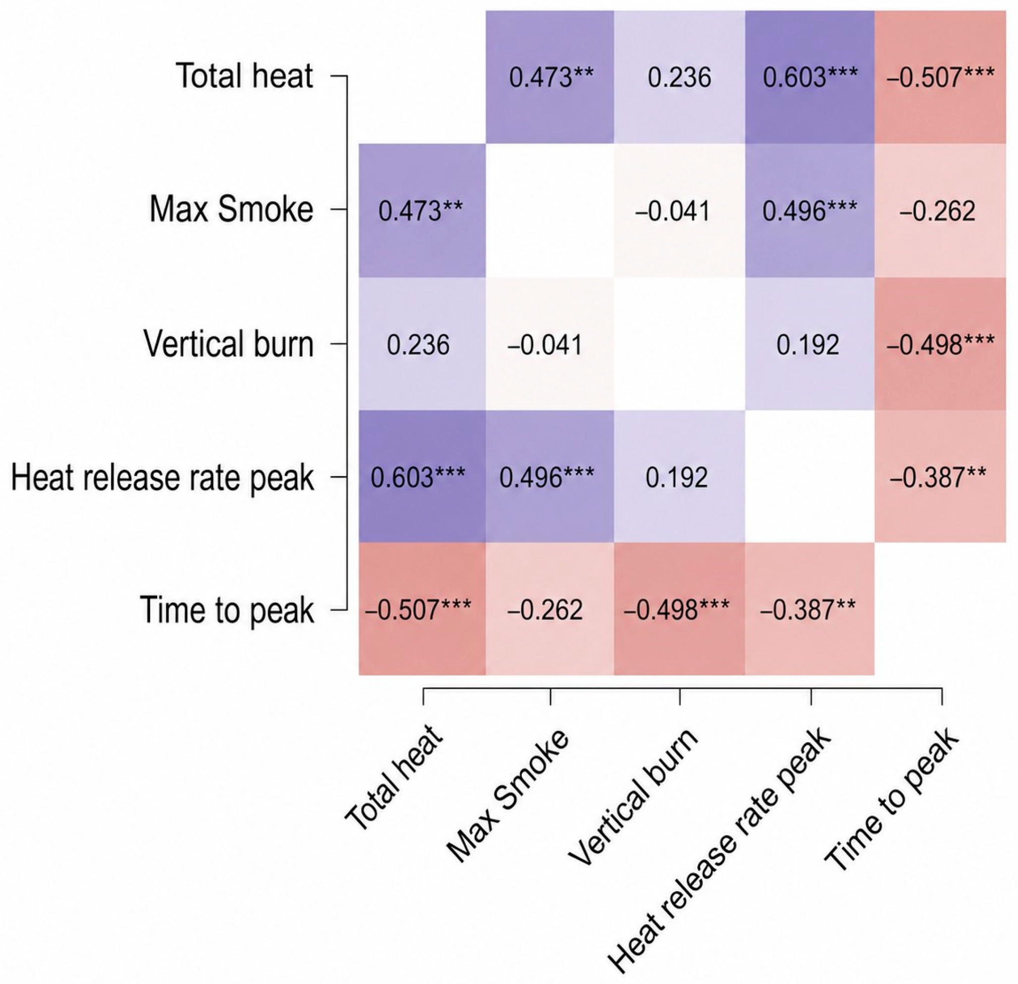
Thus, Kendall’s tau correlation analysis (Figure 5) revealed a moderate positive association between total heat and maximum smoke density (τ = 0.473, p = 0.001), indicating that samples with higher heat release tended to generate greater smoke density. Given that lower values of both parameters represent improved fire performance, this finding suggests that increases in heat release are accompanied by increased smoke production, reflecting a consistent deterioration in combustion behavior. A strong positive correlation was also observed between total heat and peak heat release rate (τ = 0.603, p < 0.001), indicating that materials with higher overall heat output also exhibit higher peak combustion intensity.
In contrast, vertical burn length was not significantly correlated with total heat (τ = 0.236, p = 0.111) or maximum smoke density (τ = −0.041, p = 0.78), nor with heat release rate peak (τ = 0.192, p = 0.19). This indicates that flame spread resistance behaves independently of heat release and smoke production. Significant negative correlations were observed between time to peak and total heat (τ = −0.507, p < 0.001), as well as vertical burn length (τ = −0.498, p < 0.001) and heat release rate peak (τ = −0.387, p = 0.009). These findings suggest that materials reaching peak combustion more rapidly tend to exhibit lower fire performance, characterized by higher heat release and reduced flame resistance.
Thus, it can be concluded that painted Ultem 9085 polymer–coating composites with higher total heat tended to exhibit greater maximum smoke density and higher peak heat release rates, suggesting a consistent decline in fire performance as combustion intensity increased. By contrast, vertical burn length showed no significant correlation with the other measured parameters, indicating that flame spread resistance may represent a distinct aspect of fire behavior. Furthermore, the negative correlations with time to peak indicated that materials that reach peak combustion more rapidly generally performed worse, with higher heat output, greater combustion intensity, and lower flame resistance. Overall, these results suggest that poor fire performance is characterized by rapid, intense combustion accompanied by elevated smoke production, while different mechanisms may govern vertical flame spread.

3.3. Tribological Properties

3.3.1. Coefficient of Friction

The coefficient of friction (CoF) between two solids is defined as the ratio of the friction force and the load or the force normal to the surface, and it is independent of the apparent area of contact [44]. The CoF is directly related to sliding resistance, wear rate, and long-term functional reliability [45] in parts such as aerospace interior components, where Ultem 9085 is commonly used [46]. The results for CoF are provided in Table 7 as the maximum peak values and the mean of the constant plateau zone of the measurement, excluding both endpoints of the oscillating motion, as in [47].
CoF was measured for all polymer–paint coating composites as an indicator of wear resistance. Thus, PP9 exhibits excellent wear performance and the lowest CoF after both 1000 and 3000 cycles. PP8 also has a low CoF, whereas the other composite systems exhibit greater surface wear and higher CoF values. For interior applications, a lower CoF indicates that a material surface has less resistance to sliding contact against an interacting surface, which is advantageous for components such as interior panels, covers, ducts, and clips, where reduced friction can promote smoother assembly and decrease rubbing forces during service [48]. However, it should be noted that the significance of a lower CoF depends on the intended function of the component. Therefore, for interior applications, a lower CoF is typically associated with improved sliding behavior, reduced wear-related interaction, and enhanced serviceability, provided that the design does not depend on high surface traction.

3.3.2. Surface 3D Texture

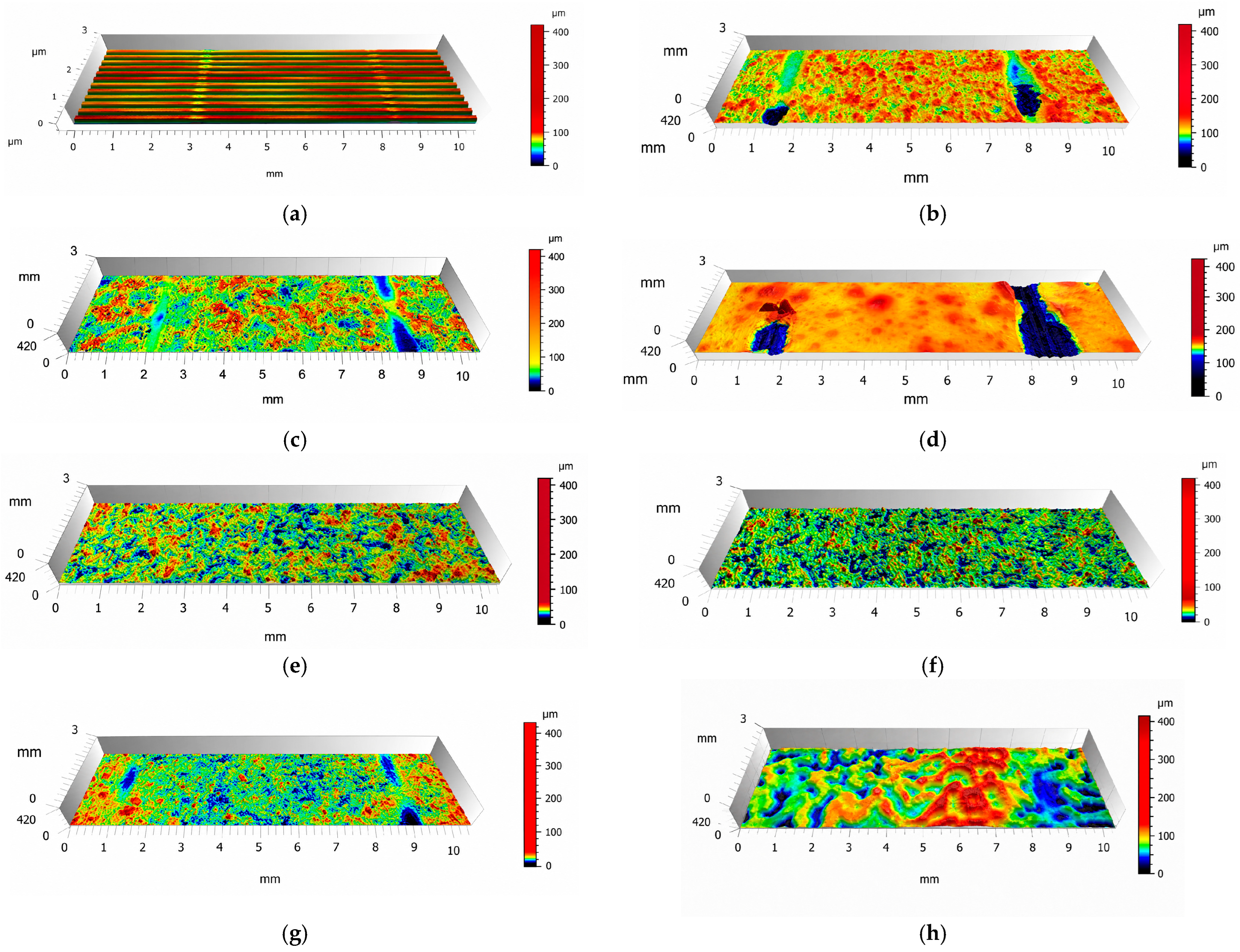
The 3D surface texture images in Figure 6 indicated substantial differences in areal topography among the investigated systems. The RAW Ultem 9085 surface (Figure 6a) exhibited a highly regular ribbed morphology, which is characteristic of FDM processing and reflected the presence of adjacent deposited roads. This periodic structure produced alternating ridges and grooves, which can promote directional sliding effects, mechanical interlocking, and localized stress concentration during frictional contact. After coating, the original FDM texture is partly or completely masked, but the resulting surface morphology strongly depends on the coating system.
The painted specimens show different degrees of surface smoothing, roughening, and localized defect formation. Some coatings produced relatively continuous and compact surfaces, whereas others contained pronounced peaks, depressions, pores, and valley-like defects. Surfaces with large height variations and isolated deep valleys are expected to experience more intense localized wear because sliding contact is initially concentrated on the highest asperities. In contrast, smoother and more homogeneous textures distributed the contact load more uniformly and therefore reduced severe abrasive or adhesive interactions. The observed textures are consistent with the results for CoF. Specimens with more homogeneous and refined surface textures, particularly PP8 and PP9, exhibited the lowest CoF values after both 1000 and 3000 cycles, suggesting that reduced roughness and more uniform surface morphology improved sliding stability. For these systems, the wear process is likely less severe and more progressive, dominated by mild polishing or gradual smoothing of the coating surface.
In contrast, PP1 and PP5 displayed more heterogeneous surface features, including pronounced irregularities and localized height variations. These features can increase mechanical interlocking between the counterface and the coating surface, resulting in higher CoF values and more intense wear [49]. In such cases, wear is likely governed by a combination of asperity removal, micro-cutting, and debris-assisted abrasion.
The intensity of wear can therefore be qualitatively ranked from the 3D texture images by considering the continuity and severity of surface defects. More uniform surfaces with fewer pronounced asperities indicate lower wear intensity and more stable frictional behavior, whereas rougher surfaces with peaks, pits, and discontinuous regions indicate higher wear intensity and a greater risk of coating damage or debris formation [50,51]. In this context, PP8 and PP9 appear to provide the most favorable tribological surface conditions, while PP1 and PP5 are more susceptible to intensified frictional interactions. Overall, the 3D texture analysis confirms that surface morphology is not only a visual consequence of coating application but also a controlling factor in the wear mechanism of painted Ultem 9085 systems. More regular and compact coating topographies are associated with lower friction and milder wear, whereas heterogeneous textures promote localized contact, higher friction, and more severe wear processes.

4. Conclusions

The main conclusions for the effects of seven aerospace-relevant paint coatings on the fire-retardant and tribological properties of FDM-manufactured Ultem 9085 can be summarized as follows:
  • All coatings reduced vertical burn length compared with uncoated Ultem 9085, indicating improved flame spread resistance. All coatings increased the peak heat release rate and smoke density, showing that improved burn resistance may be accompanied by higher heat and smoke generation. Based on the combined criteria of low HRR, low smoke density, and reduced burn length, PP4, PP1, and PP9 showed the most favorable overall fire performances.
  • Tribological behavior varied strongly, with CoF ranging from 0.2 for PP9 to 1.1 for PP5; PP7 and PP8 showed negligible wear, while PP1 and PP5 exhibited severe coating degradation.
  • Statistical analysis showed that total heat release, peak HRR, and smoke density deteriorated concurrently, whereas vertical burn length behaved independently of these parameters.
  • Overall, coating selection for Ultem 9085 should be application-specific, balancing flame spread resistance, heat and smoke generation, friction, and wear resistance.

Author Contributions

Conceptualization, E.V. and T.G.-K.; methodology, E.V.; software, B.B.; formal analysis, M.F.T. and T.G.-K.; investigation, E.V., T.G.-K., A.L. and J.L.; resources, D.D. and J.J.; data curation, E.V., A.L. and J.L.; writing—original draft preparation, E.V., T.G.-K., B.B., M.F.T., D.D., J.J., A.L. and J.L.; writing—review and editing, E.V., T.G.-K., B.B., M.F.T., D.D., J.J., A.L. and J.L.; supervision, T.G.-K.; project administration, D.D.; funding acquisition, J.J. All authors have read and agreed to the published version of the manuscript.

Funding

This research was funded by the European Union’s recovery instrument NextGenerationEU through the European Regional Development Fund (ERDF), project No. 5.1.1.2.i.0/2/24/A/CFLA/004.

Data Availability Statement

The data is available on request (elina@am-craft.com).

Conflicts of Interest

The authors declare no conflicts of interest.

Abbreviations

The following abbreviations are used in this manuscript:
AMAdditive manufacturing
ANOVAAnalysis of variance
CoFCoefficient of friction
FDMFused deposition modeling
FSTFlame, smoke, and toxicity
HRRHeat release rate
PEIPolyetherimide
PPSUPolyphenylsulfone
SDStandard deviation

References

  1. Ngo, T.D.; Kashani, A.; Imbalzano, G.; Nguyen, K.T.Q.; Hui, D. Additive manufacturing (3D printing): A review of materials, methods, applications and challenges. Compos. Part B 2018, 143, 172–196. [Google Scholar] [CrossRef]
  2. Wang, L.; Mosher, R.; Duett, P. Additive Manufacturing in the Aerospace Industry. Am. J. Eng. Appl. Sci. 2024, 17, 116–125. [Google Scholar] [CrossRef]
  3. Dhanesh, G.M.; Saiyathibrahim, A.; Gopi, S.; Vijaykumar, S.J.; Kumar, S.; Murali, K.R. Additive manufacturing for space applications: A review of materials, methods, and future frontiers. China Weld. 2025, 35, 100010. [Google Scholar] [CrossRef]
  4. Stratasys Ltd. Ultem 9085 FDM Material Datasheet. 2021. Available online: https://www.stratasys.com/en/materials/materials-catalog/fdm-materials/ultem-9085/ (accessed on 20 May 2026).
  5. Vindedze, E.; Glaskova-Kuzmina, T.; Kruuv, P.-P.; Dejus, D.; Jatnieks, J.; Jurinovs, M.; Gaidukovs, S. Comparative analysis of ISO and ASTM standards for the characterization of mechanical properties of Ultem 9085. Mech. Compos. Mater. 2025, 61, 1111–1122. [Google Scholar] [CrossRef]
  6. Vindedze, E.; Glaskova-Kuzmina, T.; Dejus, D.; Jātnieks, J.; Sevcik, S.; Bute, I.; Sevcenko, J.; Stankevich, S.; Gaidukovs, S. Effects of printing orientation on the tensile, thermophysical, smoke density, and toxicity properties of Ultem® 9085. Polymers 2025, 17, 145. [Google Scholar] [CrossRef] [PubMed]
  7. Kobenko, S.; Dejus, D.; Jātnieks, J.; Pazars, D.; Glaskova-Kuzmina, T. Structural integrity of the aircraft interior spare parts produced by additive manufacturing. Polymers 2022, 14, 1538. [Google Scholar] [CrossRef] [PubMed]
  8. Zotti, A.; Paduano, T.; Napolitano, F.; Zuppolini, S.; Zarrelli, M.; Borriello, A. Fused Deposition Modeling of Polymer Composites: Development, Properties and Applications. Polymers 2025, 17, 1054. [Google Scholar] [CrossRef]
  9. Collins Aerospace. aeroFIBER™ Honeycomb Panels. Available online: https://www.rtx.com/collinsaerospace/what-we-do/industries/business-aviation/cabin/structures/honeycomb-panels/aerofiber (accessed on 11 May 2026).
  10. Composites Knowledge Network. Fire Retardant Resins/Additives—A345. 2024. Available online: https://compositeskn.org/KPC/A345 (accessed on 12 May 2026).
  11. SABIC. LEXAN™ Copolymer FST9405T Technical Data Sheet. 2025. Available online: https://materialfinder.sabic-specialties.com/document-download/18b6102f-8df7-e611-819b-06b69393ae39 (accessed on 12 May 2026).
  12. SABIC. LEXAN™ Copolymer FST9705 Polycarbonate Technical Data. Available online: https://plastore.it/cgi2018/file818/1_pc%20lexan%20fst9705.pdf (accessed on 12 May 2026).
  13. Solvay Specialty Polymers. Radel® R-7700 Polyphenylsulfone Technical Data Sheet. Available online: https://hongrunplastics.com/public/uploads/images/20250612/Solvay%20PPSU%20Radel%20R-7700.pdf (accessed on 14 May 2026).
  14. Batista, M.; Del Sol, I.; Gómez-Parra, Á.; Vazquez-Martinez, J.M. Tribological Performance of Additive Manufactured PLA-Based Parts. Polymers 2024, 16, 2529. [Google Scholar] [CrossRef]
  15. Mittal, K.L. Polymer Surface Modification: Relevance to Adhesion, 1st ed.; CRC Press: London, UK, 2007; 314p. [Google Scholar] [CrossRef]
  16. Startsev, O.V.; Mastalygina, E.E.; Vetcher, A.A.; Koval, T.V.; Veligodsky, I.M.; Dvirnaya, E.V.; Iordanskii, A.L. Long-Term Environmental Aging of Polymer Composite Coatings: Characterization and Evaluation by Dynamic Mechanical Analysis. J. Compos. Sci. 2025, 9, 645. [Google Scholar] [CrossRef]
  17. Vahabi, H.; Laoutid, F.; Saeb, M.; Dubois, P.; Mehrpouya, M. Flame retardant polymer materials: An update and the future for 3D printing developments. Mater. Sci. Eng. R Rep. 2021, 144, 100604. [Google Scholar] [CrossRef]
  18. Kandare, E.; Kandola, B.; Myler, P. Evaluating the influence of varied fire-retardant surface coatings on post-heat flexural properties of glass/epoxy composites. Fire Saf. J. 2013, 58, 112–120. [Google Scholar] [CrossRef]
  19. Schartel, B.; Hull, R. Development of fire-retarded materials—Interpretation of cone calorimeter data. Fire Mater. 2007, 31, 327–354. [Google Scholar] [CrossRef]
  20. Malucelli, G. How to Reduce the Flammability of Plastics and Textiles through Surface Treatments: Recent Advances. Coatings 2022, 12, 1563. [Google Scholar] [CrossRef]
  21. Myshkin, N.; Petrokovets, M.I.; Kovalev, A. Tribology of polymers: Adhesion, friction, wear, and mass-transfer. Tribol. Int. 2005, 38, 910–921. [Google Scholar] [CrossRef]
  22. Ma, C.; Li, T.; Wang, Y.; Zhang, Y.; Cao, Q.; Gong, X.; Zeng, X.; Cheng, X.; Liu, K. Tribological behavior and mechanism of high-temperature self-lubricating wear-resistant composite coatings on 3D-printed SiC ceramic surfaces. J. Eur. Ceram. Soc. 2025, 45, 117473. [Google Scholar] [CrossRef]
  23. Žigon, J.; Kariž, M.; Pavlič, M. Surface Finishing of 3D-Printed Polymers with Selected Coatings. Polymers 2020, 12, 2797. [Google Scholar] [CrossRef]
  24. Boado-Cuartero, B.; Pérez-Álvarez, J.; Roibás-Millán, E. Material Characterization of High-Performance Polymers for Additive Manufacturing (AM) in Aerospace Mechanical Design. Aerospace 2024, 11, 748. [Google Scholar] [CrossRef]
  25. Formisano, A.; Boccarusso, L.; Langella, A. Surface Optimization of Components Obtained by Fused Deposition Modeling for Air-Plasma-Sprayed Ceramic Coatings. J. Compos. Sci. 2023, 7, 158. [Google Scholar] [CrossRef]
  26. Federal Aviation Regulation (FAR) Standard No. 25.853 Fire Test to Aircraft Material: Fire Protection for Compartment Interior. Federal Register: Washington, DC, USA, 1995. Available online: https://www.federalregister.gov/documents/2019/07/03/2019-13646/interior-parts-and-components-fireprotection-for-transport-category-airplanes (accessed on 20 May 2026).
  27. Federal Aviation Regulation (FAR) Standard No. 25.855 Fire Test to Aircraft Material: Cargo or Baggage Compartments. Federal Register: Washington, DC, USA, 1990. Available online: https://www.faa.gov/sites/faa.gov/files/2022-11/25.855.pdf (accessed on 20 May 2026).
  28. Glaskova-Kuzmina, T.; Dejus, D.; Jātnieks, J.; Vīndedze, E.; Bute, I.; Sevcenko, J.; Aniskevich, A.; Stankevich, S.; Boobani, B. The tensile, thermal and flame-retardant properties of polyetherimide and polyetherketoneketone processed by fused filament fabrication. Polymers 2024, 16, 336. [Google Scholar] [CrossRef] [PubMed]
  29. European Union Aviation Safety Agency. EASA CS 25.853 Appendix F. PART V of Airworthiness Standards for the Aviation Sector Part I; EASA: Cologne, Germany, 2018; Available online: https://www.easa.europa.eu/sites/default/files/dfu/CS%2025%20%28Initial%20issue%29.pdf (accessed on 20 May 2026).
  30. European Union Aviation Safety Agency. EASA CS 25.853 Appendix F. PART IV of Airworthiness Standards for the Aviation Sector Part I; EASA: Cologne, Germany, 2018. [Google Scholar]
  31. Federal Aviation Administration. Aircraft Materials Fire Test Handbook, DOT/FAA/AR-00/12. 2000. Available online: https://www.fire.tc.faa.gov/pdf/00-12.pdf (accessed on 14 May 2026).
  32. Lyon, R.E. Materials with Reduced Flammability in Aerospace and Aviation. In Advances in Fire Retardant Materials; CRC Press: Boca Raton, FL, USA, 2008. [Google Scholar] [CrossRef]
  33. Sabee, M.M.S.M.; Itam, Z.; Beddu, S.; Zahari, N.M.; Kamal, N.L.M.; Mohamad, D.; Sapuan, S.M. Flame Retardant Coatings: Additives, Binders, and Fillers. Polymers 2022, 14, 2911. [Google Scholar] [CrossRef] [PubMed]
  34. Liu, W.; Chen, D.-Q.; Wang, Y.-Z.; Wang, D.-Y.; Qu, M.-H. Char-forming mechanism of a novel polymeric flame retardant with char agent. Polym. Degrad. Stab. 2007, 92, 1046–1052. [Google Scholar] [CrossRef]
  35. Duquesne, S.; Le Bras, M.; Bourbigot, S.; Delobel, R.; Camino, G.; Eling, B.; Lindsay, C.; Roels, T. Thermal degradation of polyurethane and polyurethane/expandable graphite coatings. Polym. Degrad. Stab. 2001, 74, 493–499. [Google Scholar] [CrossRef]
  36. Li, Y.; Cao, C.-F.; Chen, Z.-Y.; Liu, S.-C.; Bae, J.; Tang, L.-C. Waterborne Intumescent Fire-Retardant Polymer Composite Coatings: A Review. Polymers 2024, 16, 2353. [Google Scholar] [CrossRef]
  37. Lv, Y.; Dejus, D.; Kobenko, S.; Singamneni, S.; Glaskova-Kuzmina, T. Evaluation of the Fire-retardancy of ULTEM 9085 Polymer Composites Processed by Fused Deposition Modelling. Mater. Sci. (Medžiagotyra) 2022, 28, 353–359. [Google Scholar] [CrossRef]
  38. Hull, T.R.; Stec, A.A.; Lebek, K.; Price, D. Factors affecting the combustion toxicity of polymeric materials. Polym. Degrad. Stab. 2007, 92, 2239–2246. [Google Scholar] [CrossRef]
  39. Alarifi, A.A.; Andrews, G.E.; Witty, L.; Phylaktou, H.N. Ignition and Toxicity Evaluation of Selected Aircraft Interior Materials Using the Cone Calorimeter and FTIR Analysis. In Proceedings of the Interflam 2013, London, UK, 24–26 June 2013; pp. 37–48. Available online: https://eprints.whiterose.ac.uk/id/eprint/83290 (accessed on 14 May 2026).
  40. National Archives and Records Administration. 14 CFR Part 25, Appendix F to Part 25: Test Method to Determine the Smoke Emission Characteristics of Cabin Materials. Electronic Code of Federal Regulations. 2026. Available online: https://www.ecfr.gov/current/title-14/chapter-I/subchapter-C/part-25/appendix-Appendix%20F%20to%20Part%2025 (accessed on 22 April 2026).
  41. Babrauskas, V.; Peacock, R.D. Heat release rate: The single most important variable in fire hazard. Fire Saf. J. 1992, 18, 255–272. [Google Scholar] [CrossRef]
  42. CS-25/EASA Easy Access Rules for Large Aeroplanes, Appendix F, Part IV. Available online: https://www.easa.europa.eu/en/document-library/easy-access-rules/online-publications/easy-access-rules-large-aeroplanes-cs-25?page=68&utm_source (accessed on 14 May 2026).
  43. Liang, S.; Neisius, N.M.; Gaan, S. Recent developments in flame retardant polymeric coatings. Prog. Org. Coat. 2013, 76, 1642–1665. [Google Scholar] [CrossRef]
  44. Persson, B.N.J. Sliding Friction: Physical Principles and Applications; Springer Science & Business Media: Berlin/Heidelberg, Germany, 2013. [Google Scholar] [CrossRef]
  45. Ren, Y.; Zhang, L.; Xie, G.; Li, Z.; Chen, H.; Gong, H.; Xu, W.; Guo, D.; Luo, J. A review on tribology of polymer composite coatings. Friction 2021, 9, 429–470. [Google Scholar] [CrossRef]
  46. Mitaľ, G.; Gajdoš, I.; Spišák, E.; Majerníková, J.; Jezný, T. An analysis of selected technological parameters’ influences on the tribological properties of products manufactured using the FFF technique. Appl. Sci. 2022, 12, 3853. [Google Scholar] [CrossRef]
  47. Briede, S.; Platnieks, O.; Barkane, A.; Sivacovs, I.; Leitans, A.; Lungevics, J.; Gaidukovs, S. Tailored biobased resins from acrylated vegetable oils for application in wood coatings. Coatings 2023, 13, 657. [Google Scholar] [CrossRef]
  48. Fischer, M.; Schöppner, V. Some Investigations regarding the surface treatment of Ultem 9085 parts manufactured with fused deposition modeling. In Proceedings of the 24th International SFF Symposium—An Additive Manufacturing Conference, SFF 2013, University of Texas at Austin, Austin, TX, USA, 12–14 August 2013; pp. 805–815. [Google Scholar] [CrossRef]
  49. Norani, M.N.M.; Abdollah, M.F.B.; Abdullah, M.I.H.C.; Tamaldin, N.; Amiruddin, H. Mechanical and tribological properties of FFF 3D-printed polymers: A brief review. J. Tribol. 2021, 29, 11–30. [Google Scholar]
  50. Golhin, A.P.; Tonello, R.; Frisvad, J.R.; Grammatikos, S.; Strandlie, A. Surface roughness of as-printed polymers: A comprehensive review. Int. J. Adv. Manuf. Technol. 2023, 127, 987–1043. [Google Scholar] [CrossRef]
  51. Dangnan, F.; Espejo, C.; Liskiewicz, T.; Gester, M.; Neville, A. Friction and wear of additive manufactured polymers in dry contact. J. Manuf. Process. 2020, 59, 238–247. [Google Scholar] [CrossRef]
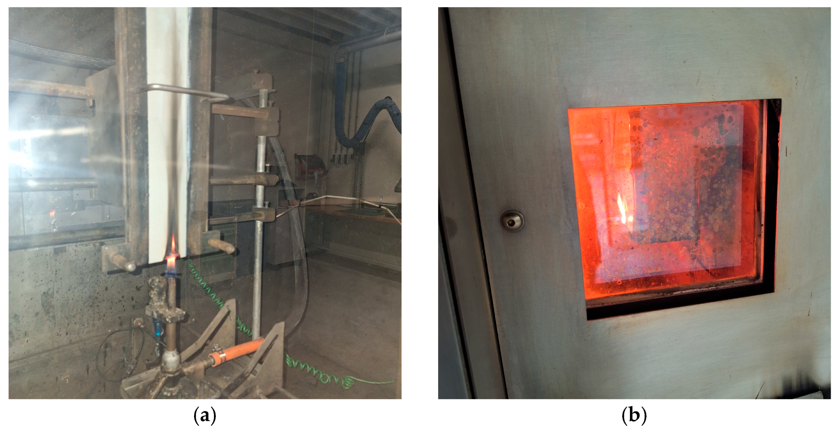
Figure 1. (a) Vertical burn test setup in HVFAA equipment, and (b) smoke and toxicity testing setup by using NBS smoke chamber ME1100-1.
Jcs 10 00295 g001
Figure 2. (a) A ball-on-disc tribometer, TRB 3, and (b) 3D profilometer AVANT FTA-S4 S3000-D.
Jcs 10 00295 g002
Figure 3. Maximal smoke density for different materials (bars) and maximal value according to CS/FAR 25.853 App. F Part V/ASTM F814-83 (line).
Jcs 10 00295 g003
Figure 4. (a) Peak HRR and (b) total HRR for different materials (bars) and the maximal value according to CS/FAR 25.853 App. F Part IV (line).
Jcs 10 00295 g004
Figure 5. The correlation map between the groups by using Kendall’s tau correlation analysis. ** p < 0.01, *** p < 0.001.
Jcs 10 00295 g005
Figure 6. Surface 3D texture for different materials studied: (a) RAW, (b) PP1, (c) PP4, (d) PP5, (e) PP7, (f) PP8, (g) PP9, and (h) PP14.
Jcs 10 00295 g006
Table 1. Printing parameters.
ParameterValue
Raster width, mm 0.508
Number of contours1
Slice height, mm0.254
Raster angle±45°
Raster to raster air gap, mm0
Infill density, %100
Table 2. Polymer–paint coating composites’ data.
Layer/Paint SystemRAWPP1PP4PP5PP7PP8PP9PP14
Primer 1,2N/AALEXIT Primefill 500ALEXIT Primefill 500ALEXIT Primefill 500ALEXIT Primefill 500ALEXIT Primefill 500ALEXIT Primefill 500N/A
Color/top coat 1N/AALEXIT 346-57ALEXIT 346-55ALEXIT 404-12 (smooth)ALEXIT-Suede-Coating 404-74ALEXIT-FST-Microeffekt 404-75ALEXIT-Selftex 100 whiteLaminate white Isovolta AIRDEC-F3 (HAA) (Wiener Neudorf, Austria)
Color/top coat 2N/AALEXIT 346-57ALEXIT 346-55ALEXIT 404-12 (texture)
Color/top coat 3N/A ALEXIT 404-54
Clear coatN/A ALEXIT 404-15
Total coating thickness, µmN/A150 ± 15120 ± 15200 ± 40120 ± 25120 ± 20120 ± 20250 ± 5
Table 3. Vertical burn length of uncoated Ultem 9085 and painted polymer–coating composites (n = 3 per group; CS/FAR 25.853 App. F Part I; limit: 150 mm).
MaterialBurn Length, mm (Mean ± SD)Δ vs. RAW, %Pass (≤150 mm)
RAW95.67 ± 6.03Pass
PP174.67 ± 4.73−21.95Pass
PP479.33 ± 2.31−17.07Pass
PP555.67 ± 2.08−41.81Pass
PP791.33 ± 3.21−4.53Pass
PP888.00 ± 3.00−8.01Pass
PP972.67 ± 0.58−24.04Pass
PP1478.33 ± 7.64−18.12Pass
Table 4. Toxic gas concentrations released during the combustion of uncoated Ultem 9085 and painted polymer–coating composites.
MaterialHCNCONOxSO2HFHCl
RAW0.50 ± 0.0074.67 ± 17.933.17 ± 0.471.67 ± 0.5803.33 ± 0.58
PP13.83 ± 1.04128.33 ± 24.508.00 ± 0.726.33 ± 1.1504.33 ± 1.15
PP45.00 ± 0.00104.00 ± 22.655.10 ± 0.361.67 ± 0.58066.67 ± 15.28
PP51.67 ± 0.5896.00 ± 9.544.27 ± 0.152.00 ± 0.00026.67 ± 2.89
PP74.67 ± 0.58123.67 ± 23.185.00 ± 0.601.67 ± 0.58033.33 ± 15.28
PP83.00 ± 0.00104.67 ± 17.045.20 ± 0.442.67 ± 0.58025.00 ± 5.00
PP92.00 ± 0.0088.67 ± 18.014.17 ± 0.251.67 ± 0.58033.33 ± 15.28
PP141.67 ± 0.58145.67 ± 37.614.07 ± 0.594.67 ± 1.53028.33 ± 2.89
ABD 0031 (Airbus), ppm1501000100100100150
D6-51377 (Boeing), ppm150Ref. only100100200500
Table 5. Time to peak for uncoated Ultem 9085 and painted polymer–coating composites.
MaterialTime to Peak, s (Mean ± SD)
RAW52.3 ± 5.9
PP175.0 ± 28.7
PP451.3 ± 1.4
PP5103.3 ± 40.3
PP715.7 ± 2.1
PP818.7 ± 1.5
PP9114.0 ± 15.1
PP1421.0 ± 0.0
Table 6. Descriptive statistics for all groups (painted Ultem 9085 polymer–coating composites).
GroupNumberMeanSD
Total heat, kW∙min/m22456.6311.74
Max smoke density2450.3325.37
Vertical burn length, mm2479.4512.56
Heat release rate peak, kW∙min/m22447.126.96
Time to peak, s2459.9147.65
Table 7. CoF for different polymer–paint coating composites after 1000 and 3000 cycles.
MaterialMax CoF
1000 Cycles
Max CoF
3000 Cycles
Mean CoF ± SD
1000 Cycles
Mean CoF ± SD
3000 Cycles
RAW0.6250.6810.450 ± 0.0520.469 ± 0.082
PP10.9850.990.423 ± 0.1320.460 ± 0.161
PP40.7450.9120.531 ± 0.0890.577 ± 0.085
PP51.0061.1120.497 ± 0.1390.493 ± 0.175
PP70.4040.5420.259 ± 0.0350.280 ± 0.078
PP80.2610.3050.178 ± 0.0280.188 ± 0.026
PP90.2110.2120.145 ± 0.0110.143 ± 0.019
PP140.7810.8750.371 ± 0.1020.466 ± 0.169
Disclaimer/Publisher’s Note: The statements, opinions and data contained in all publications are solely those of the individual author(s) and contributor(s) and not of MDPI and/or the editor(s). MDPI and/or the editor(s) disclaim responsibility for any injury to people or property resulting from any ideas, methods, instructions or products referred to in the content.