1. Introduction
The Fused Filament Fabrication (FFF) technique is one of the most well-known and widely employed additive manufacturing processes on a global scale and has rapidly progressed into a revolutionary production technology, owing to its versatility, efficiency, and capacity for manufacturing complex geometries in a simplified way, utilizing various materials, including thermoplastic polymers and advanced materials [
1,
2].
Over the last few years, the capabilities and features of three-dimensional printers have undergone significant advancements, enabling the use of multiple materials within a single printing process. As a consequence, multi-material 3D printing plays a significant role in recent studies, and this approach allows designers to strategically merge rigid and flexible polymers, reinforced composites, or other material combinations within a unified structure. In particular, tailoring and controlling the material distributions within a 3D-printed structure could lead to a more functional printed construct with enhanced mechanical properties. Additionally, incorporating multi-material joints with thermal and mechanical interlocks, such as tau-shaped and fillet-based geometries, has been shown to improve load transfer, interfacial stability, and overall mechanical performance [
3,
4].
The integration of multi-material 3D printing with complex constructs, such as honeycomb and lattice structures, has attracted substantial attention due to their exceptional features. In addition to improving structural efficiency, these complex and lightweight structures allow customized performance for particular uses [
5,
6]. This combination of structural complexity and multi-material adaptability is very promising for industries, including biomedical, automotive, and aerospace, making them particularly suitable for advanced structural applications [
7]. The mechanical behavior and structural reliability of 3D-printed structures are significantly improved by the use of multi-material joint arrangements [
8,
9]. Both mechanical and thermal interlocking designs can be achieved within lattice structures by combining thermoplastic polymers or composite materials, with carefully placed struts offering exact control over load transfer and stress distribution. While mechanical interlocks, like tau-shaped or fillet-based geometries, improve interfacial uniformity and lower stress concentrations, thermal interlocks affect material fusing at the interface [
10,
11]. Analytical research showing the connections between geometry, load capacity, and failure patterns could also be used to evaluate the implications of various interlock designs and material arrangements on structural performance [
12].
For instance, Zhang et al. [
13] presented that dual-component 3D printing of PA and CF/PA enables the fabrication of lightweight constructs with improved mechanical performance. Interlocking bonding and optimized CF/PA reinforcement significantly enhanced the tensile, compressive, and bending properties, while decreasing stress concentrations in re-entrant structures. Modified re-entrant cores with skin panels demonstrated stable load-bearing behavior and enhanced energy absorption. The results from the current study provide practical guidance for designing multi-material 3D-printed components for various applications, such as lightweight constructs, shock absorption, and biomedical implants.
Peeke et al. [
14] exhibited a dual-extrusion 3D-printing procedure merging thermoplastics and silicone to fabricate composites with tailored mechanical performance. Thermoplastic reinforcement effectively enhances initial stiffness, while silicone provides elasticity, with controllable performance through the infill, mesh pattern, and volume ratio. Multiple thermoplastic polymers (ABS, Nylon, PETG) and grid patterns were successfully shown, displaying trustworthy manufacturing. This research enables the development of composite structures with adjustable stiff-soft behavior, as well as expanding the range of materials available for additive manufacturing applications. Wang et al. [
15] developed dual-material auxetic metamaterials fabricated via 3D printing to tailor mechanical properties through geometry and material distribution. Finite-element analysis and experimental outcomes reveal that both material selection and the proportion of stiff phase significantly affect Poisson’s ratio and stiffness, yielding mechanical behavior distinct from single-material configurations. These results highlight their potential for applications requiring adaptable and impact-resistant performance.
According to a study by Dong et al. [
16], dual-material 3D printing of TPU and PLA significantly improved honeycomb constructs. The curved re-entrant design raised stiffness, while soft TPU interlayers decreased stress concentration, delayed densification, and enhanced strength. Moreover, dual-material constructs accomplished a higher modulus, greater densification strain, and 33% strength relative to single-material structures. Su et al. [
17] developed a dual-material re-entrant construct with soft arched beams and hinges, indicating that reducing hinge strength can substantially limit beam and wall collapse. Furthermore, Saxena et al. [
18] investigated multi-material auxetic cellular designs utilizing finite-element analysis to overcome the limited stiffness range of conventional single-material architectures. The outcomes indicate that incorporating material gradients within the unit cell enables effective tailoring of stiffness while preserving auxetic behavior governed by geometry. The findings of the study show the potential of multi-material structures for applications such as wearable impact protection devices requiring adjustable stiffness distributions. Gohar et al. [
19] developed modified auxetic constructs and examined their compressive behavior through experiments and finite-element analysis. The results demonstrate enhanced stiffness and energy absorption compared to conventional re-entrant constructs. In addition, shape optimization further refines their mechanical performance. Overall, combining structural design modifications with optimization techniques enables the progress of advanced auxetic materials for high-load applications. Johnston and Kazanci [
20] compared re-entrant, anti-tetrachiral, and hexagonal honeycomb structures utilizing single-material PLA and dual-material combinations (PLA/Nylon and PLA-TPU). There was a development of a quasi-static compression finite-element model to investigate dual-material cellular constructs, which was evaluated through experiments on 3D-printed specimens. According to the results, the single-material structures provide higher energy absorption under single loading cycles, making them suitable for resilient applications. However, multi-material structures perform better under repeated loading as a result of elastic buckling provided by the incorporation of softer materials, which extends the elastic deformation phase.
Furthermore, Qi et al. [
21] investigated advanced honeycomb design strategies and classified them into macro-scale (hierarchical, graded, disordered) and meso-scale (hybrid, curved ligament, reinforced strut) designs, presenting significant enhancements in stiffness, strength, and energy absorption. Kuipers et al. [
22] presented the Interlaced Topologically Interlocking Lattice (ITIL), a fully interlocking 3D construct optimized for tensile strength, indicating that the diagonal ITIL variant generally outperforms straight and dovetail designs, while simulations and analytical models guide optimal design depending on geometric limitations. In parallel with experimental developments, significant efforts have been devoted to the analytical modeling of multi-material honeycombs, particularly through homogenization approaches for predicting equivalent in-plane elastic properties. A recent study has proposed formulations that explicitly determine the axial and bending deformation of multi-material cell walls, enabling the derivation of analytical expressions for the equivalent elastic moduli of multi-material honeycombs [
23]. These approaches highlight the critical role of material distribution and joint stiffness in governing the global mechanical response, while providing a direct link between microstructural design and macroscopic behavior. Recent advances in multi-material fused deposition modeling have demonstrated the potential of combining rigid and soft polymers to enhance the mechanical performance and functional response of honeycomb metamaterials. In particular, blending-based FDM strategies have been shown to significantly improve interfacial bonding and enable tunable energy dissipation and reusability, offering a promising pathway for the development of high-performance multi-material cellular structures [
24,
25]. A recent review study has summarized the current state-of-the-art in honeycomb structures, highlighting that the accurate prediction of their equivalent mechanical properties remains a challenging task due to the combined influence of geometry, material distribution, and deformation mechanisms [
26].
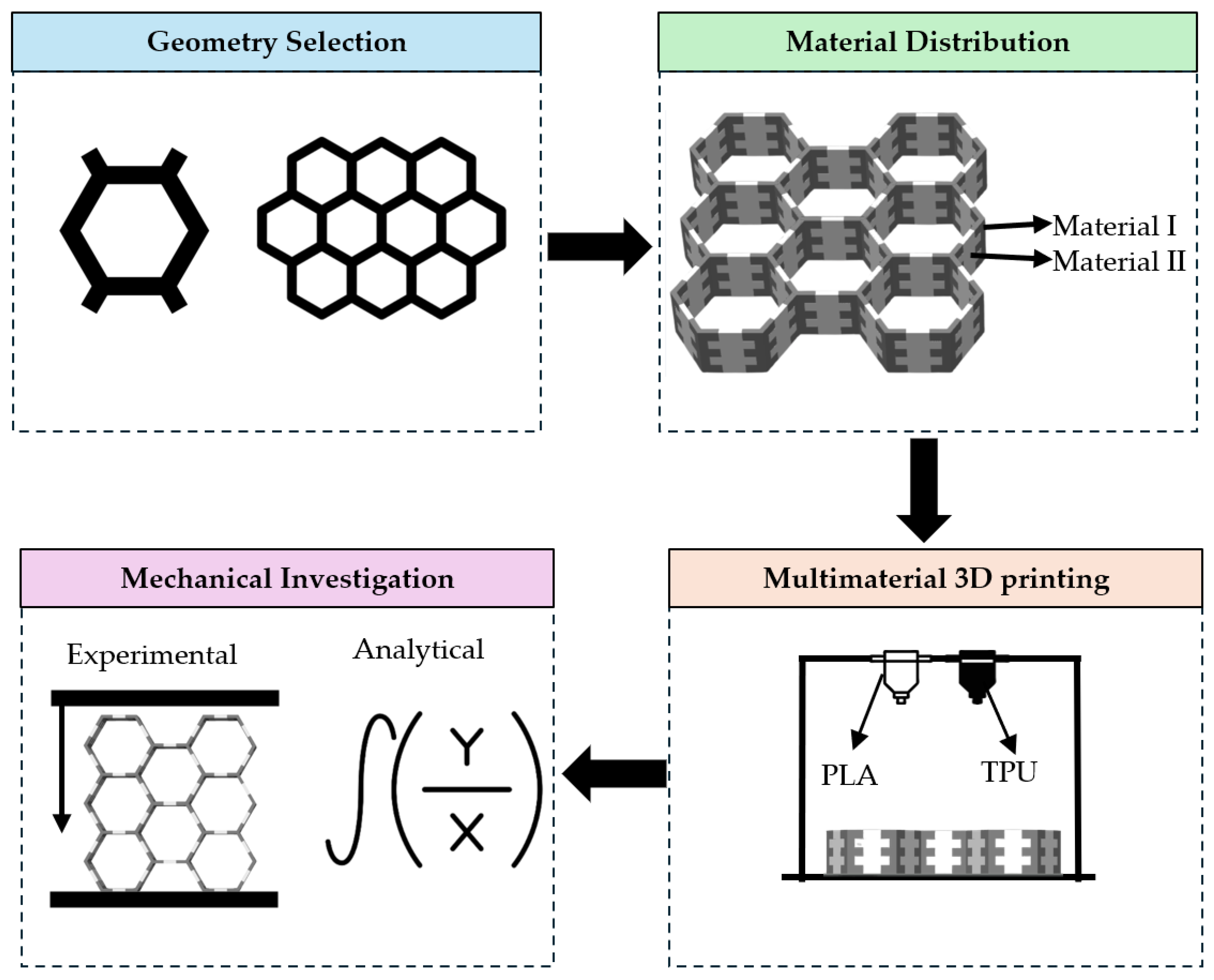
The present study investigates the mechanical performance of FFF 3D-printed honeycomb structures made of a range of TPU/PLA multi-material joint combinations. Particular emphasis is given to mechanically interlocked TPU/PLA joint configurations based on tau-shaped and teeth-based geometries. An analytical–experimental framework has been developed to evaluate the force–displacement response in order to establish a direct link among material distribution, interlocking design, and the governing deformation mechanisms. To provide a clear overview of the methodology developed in this work,
Figure 1 presents a schematic illustration of the overall framework.
2. Materials and Methods
2.1. Design Interlocking Mechanisms
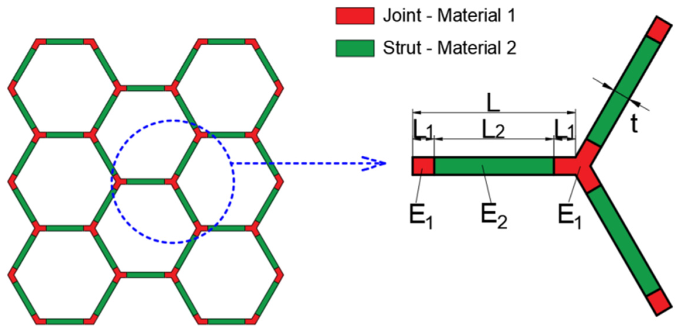
The honeycomb structures were designed with the aid of Solidworks™ Version PDM 2023 (Dassault Systemes SE, Vélizy-Villacoublay, France). For the design process, the honeycomb unit cell was divided into the angular part and the straight part. This division allowed for the development of a scalable and replicable unit cell.
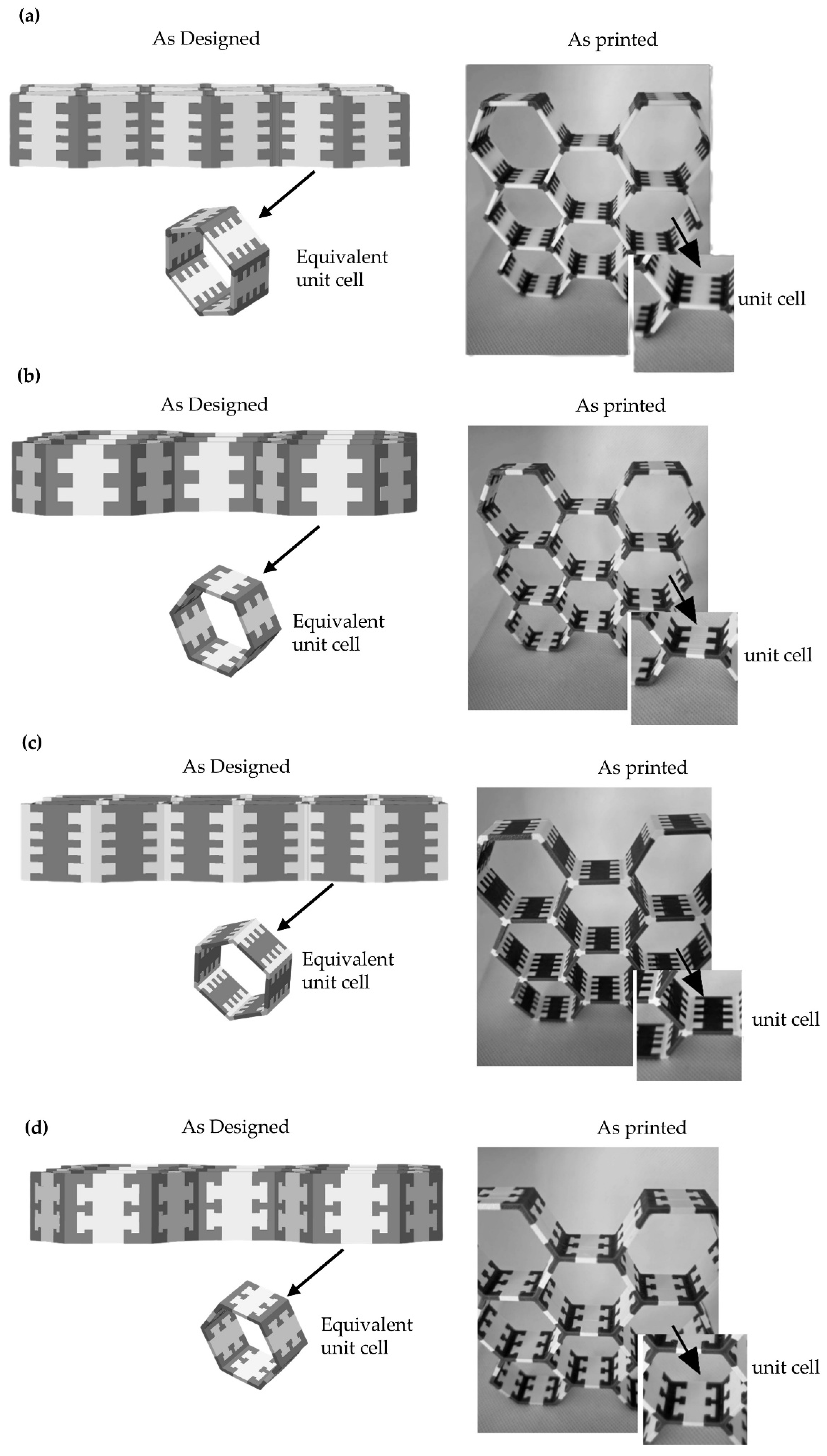
Figure 2 illustrates the different interlocking configurations considered in this study. A 3 × 3 honeycomb structure was designed, and different variations of mechanical interlocking for the straight and the angular parts were applied for each different use case scenario. The unit cell has dimensions of L = 20 mm, and the out-of-plane dimension is 20 mm. The length L
1, corresponding to the interlocking region, was selected to be approximately equal to the thickness (t) of the structural member, following Saint-Venant’s principle. This choice ensures that the geometrical discontinuity introduced by the interlocking feature affects only a localized region near the interface, while the remaining part of the strut can be treated consistently with classical beam theory assumptions. According to this, stress concentrations and deviations from classical beam theory are localized within a region of the order of the characteristic cross-sectional dimension. Therefore, by setting L
1 ≈ t = 2 mm, the geometrical discontinuity introduced by the interlocking feature is confined within a limited zone, ensuring that the remaining portion of the strut behaves consistently with beam theory assumptions.
2.2. Materials and Multimaterial Additive Manufacturing
For the development of the dual-material honeycomb structure, a combination of a thermoplastic and a thermoplastic elastomer was selected. Polylactic acid (PLA) was used as the rigid phase due to its high stiffness and dimensional stability, while thermoplastic polyurethane (TPU 95A) was used as the flexible phase, owing to its high elasticity and energy absorption capability. The TPU 95A filament (Bambu Lab, Shenzhen, China) and PLA filament (Bambu Lab, Shenzhen, China) were utilized for the fabrication of the honeycomb structures.
A Bambu Lab H2D Pro (Bambu Lab, Shenzhen, China) 3D printer equipped with two 0.4 mm diameter nozzles was used. An Automated Material System (AMS) was utilized for the storage and acquisition of the PLA filament into the printer, while the TPU filament was set into the external holder. The route between the stored filament and the nozzle was minimized to eliminate possible clogging issues or broken filament issues due to TPU’s high viscosity and elasticity. Both materials were printed in similar temperature ranges and with similar chamber and print plate temperatures, which is a crucial aspect of assessing material compatibility. In
Table 1, the printing conditions for the utilized filaments are presented. For all materials, 100% infill density was selected, and the printing pattern was concentric.
Figure 3 presents the as-printed dual-material honeycomb structures corresponding to the different interlocking configurations examined in this study, namely TPU corners with 4 teeth, TPU corners with 3 teeth, PLA corners with 4 teeth, and Tau interlocking with 3 teeth. The investigated configurations were selected to enable a focused comparison of the main parameters governing the structural response of the dual-material honeycombs. The TPU-corners 3-teeth and 4-teeth designs were used to examine the effect of tooth number under the same material distribution, while the PLA-corners configuration allowed the influence of reversed material placement between nodes and struts to be assessed. The tau interlocking design was included as a different interlocking topology to evaluate its effect on deformation stability at large compressive strains. Thus, the selected configurations represent targeted design cases for comparing material distribution, tooth number, and interlocking topology.
2.3. Mechanical Testing Under Compression
To carry out the compression tests, a Testometric M500-50AT (Testometric Company, Rochdale, UK) with a maximum load capacity of 500 N was utilized. The cross-head speed was set at 5 mm/min, and the sampling rate was 50 Hz. The compression test was terminated when the deformation reached 95% of the original specimen height. The structural integrity was monitored throughout the tests, with particular emphasis on crack initiation and propagation. For each type of produced honeycomb structure, three specimens were manufactured and tested under the aforementioned conditions. For the exportation of the mechanical response curves for each time sample, the average value was calculated and utilized for the identification of the final response curve.
2.4. Finite Element Analysis of the Deformation Mechanisms
The computational honeycomb model was developed with the aid of ANSYS™ Version 2026 R1 (ANSYS, Inc., Canonsburg, PA, USA) software. The conditions of the compression testing were simulated to export results regarding the deformational behavior of the elastic and plastic components of the overall assembly. The material properties were applied based on the filament’s manufacturer data, and the speed and time of the model matched the experimental process parameters. For the mesh conditions, the Solid 285 model was utilized, and a total of 125,000 elements were produced. Finer mesh was applied on the contact regions between the structure and the experimental machine, and also on the interface between the components, and more broadly on the parts where no significant bending was expected.
3. Results
The experimental findings from the compression tests are shown in this section, together with the related analytically generated data. The force–displacement behavior of the various configurations’ mechanical reaction is analyzed, emphasizing the impact of interlocking geometry and material distribution. In order to test the accuracy of the suggested model, a comparison between the experimental and analytical data is also carried out.
3.1. Mechanical Behavior Under Compression
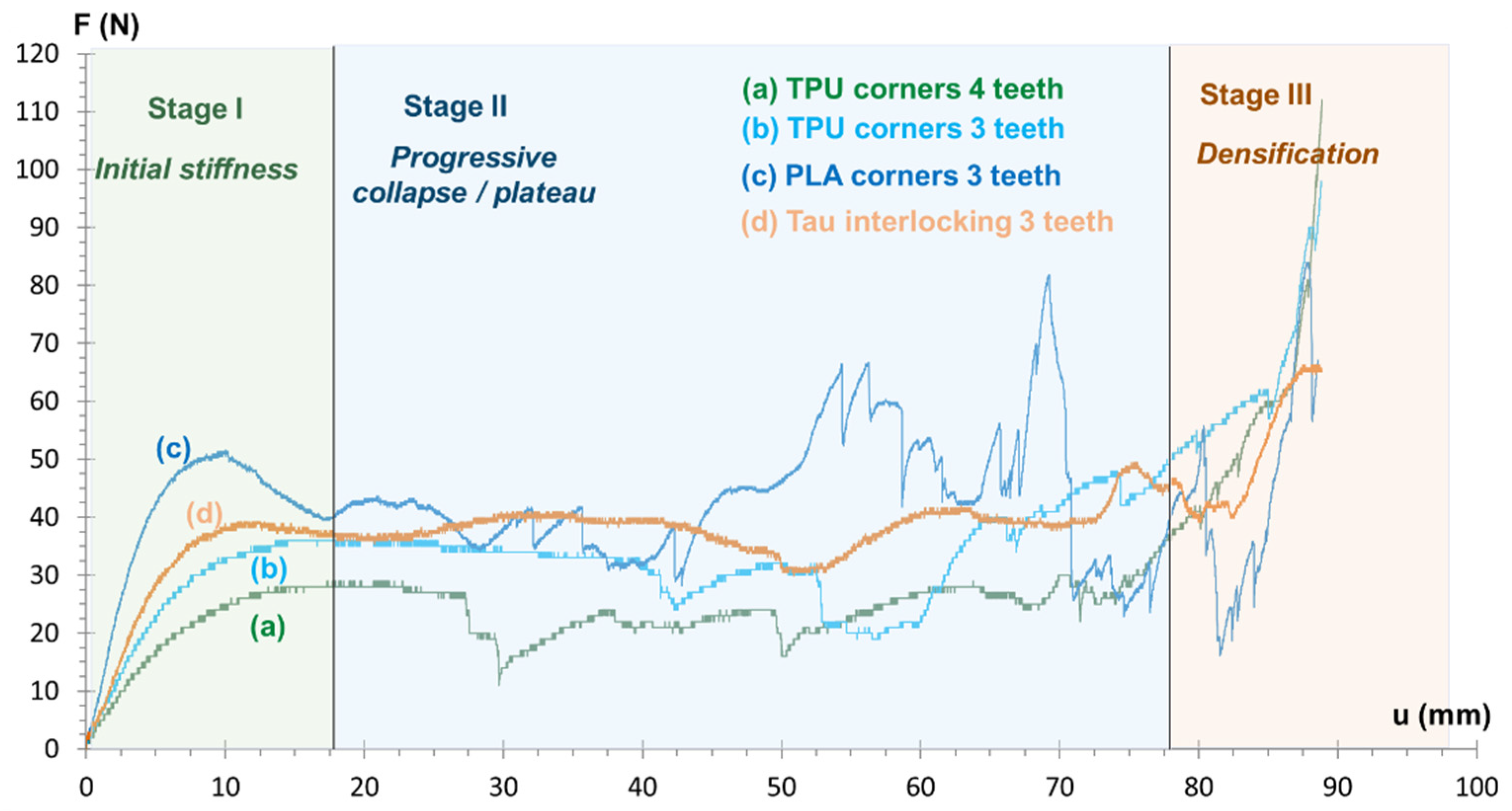
From the force–displacement curves, as shown in
Figure 4, the observations from the experimental procedure are that, for all cases of cellular structures, there are three distinct stages: a first ascending branch resulting from the initial stiffening, a region of gradually decreasing or even constant strength, and a third stage (densification stage) that shows a sharp increase in force in the case where the displacement increases significantly.
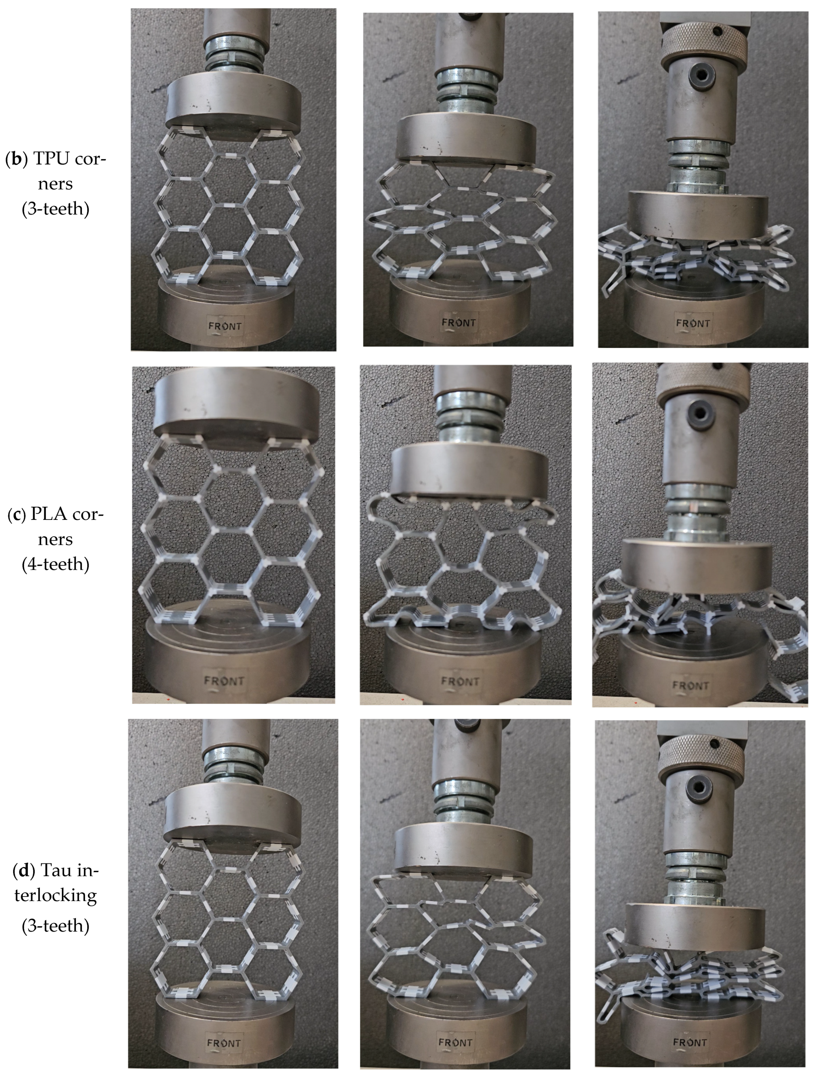
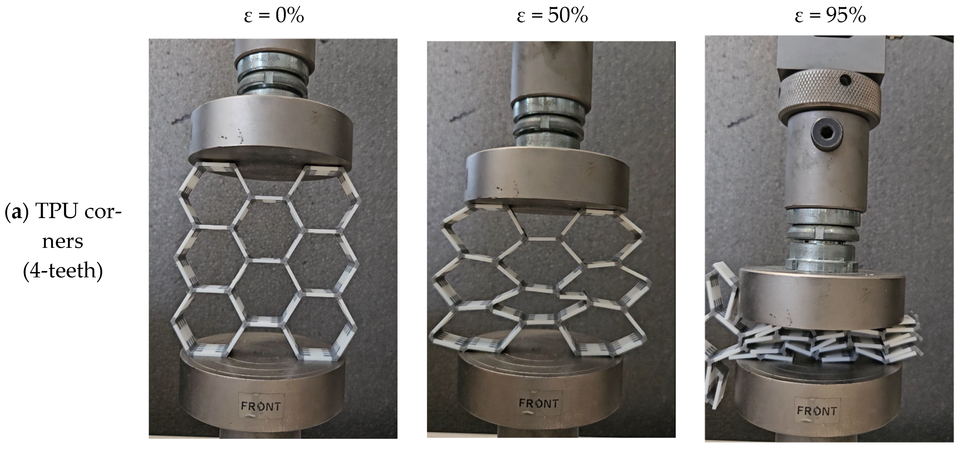
The configuration with PLA at the nodes and TPU at the struts, known as PLA-corners, exhibited the highest peak force among the examined cases. However, despite its superior load-carrying capacity, a loss of structural integrity has been observed at approximately 50% strain, where the honeycomb structure undergoes significant damage and loss of structural stability of the 3D-printed struts, as shown in
Figure 5.
The load-carrying capacity of the TPU-corners configurations, in which PLA is positioned at the struts and TPU at the nodes, is marginally reduced. The three-teeth interlocking design outperforms the four-teeth configuration among these scenarios, suggesting that the efficiency of the interlocking geometry is crucial for maintaining deformation stability during compression. This is evident in
Figure 5, where the three-teeth interlocking design has a better deformation performance at 95% strain, while the four-teeth interlocking design has a lot of damage and a loss of structural integrity. The combination of flexible TPU nodes, which offer stable support and efficient load redistribution, and stiff PLA struts, which can withstand significant bending deformation without premature failure, is responsible for the enhanced behavior. This material arrangement slows the emergence of localized instability and improves the honeycomb’s structural adaptability.
Although the Tau interlocking configuration exhibits lower force levels compared to the PLA-corners case, it demonstrates a fundamentally different mechanical response under compression. More specifically, it is the only configuration that maintains its structural integrity under large deformation, as shown in
Figure 5. Partial shape recovery was observed upon unloading, suggesting an increased elastic contribution associated with the TPU-dominated deformation mechanism. This behavior is attributed to a particular interlocking shape, which seems to offer effective mechanical engagement and enable a more stable transfer of load between the material intersections. In contrast, the remaining configurations experience significant structural damage, including fracture and interfacial failure, leading to irreversible deformation. Furthermore, the Tau configuration demonstrates a relatively stable force–displacement response, characterized by the absence of significant fluctuations in the collapse regime and a more uniform deformation process following yielding.
All specimens reach the densification stage at large displacements, where contact between collapsing cell walls causes a rapid increase in the force. Densification begins at comparable displacement levels in all configurations, indicating that the geometry of the honeycomb structure is the primary determinant at this stage, rather than the material arrangement.
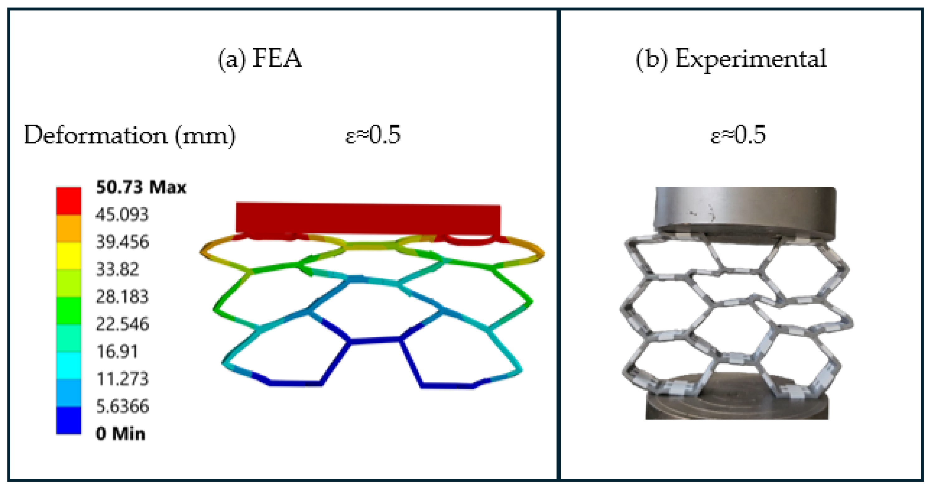
The deformation mechanisms were further investigated using a finite-element analysis. The aim of this analysis was to provide a qualitative interpretation of the deformation response and to verify whether the numerically predicted deformation pattern follows the experimentally observed trends.
Figure 6 presents an indicative comparison between the experimental observation and the finite-element prediction for the tau-interlocking configuration at 50% compressive strain. The comparison shows that the FE model captures the main bending-dominated deformation pattern and the progressive collapse behavior observed experimentally. The bending-dominated deformation is mainly evident near the corners, where the presence of a more compliant TPU phase allows local deformation, maintaining the structural integrity of the overall honeycomb geometry.
3.2. Proposed Analytical–Experimental Model
3.2.1. Analytical Force–Displacement Model
The mechanical behavior of the investigated dual-material honeycomb structures was interpreted through a combined analytical and beam-lattice modeling framework, aiming to relate the experimentally observed force–displacement response to the underlying deformation mechanisms at the cell level. The compressive response of such cellular systems is characterized by three distinct regimes, namely an initial stiffness-dominated region, a progressive collapse stage associated with local instabilities, and a final densification phase governed by contact between collapsed cell walls. In order to capture these mechanisms within a unified formulation, a phenomenological force–displacement relationship was introduced. The response is expressed as:
where
F is the applied force,
u is the imposed displacement, and
H is the total specimen height. It is noted that the Macaulay bracket
is taken into account only after the onset of significant structural collapse, i.e., only when the value of the displacement
u exceeds the value
ud. The first term of the equation represents the initial structural response of the honeycomb. The parameter
Keff corresponds to the effective stiffness of the structure, while the exponential factor
takes into account the gradual degradation of stiffness due to early-stage local instabilities, rotational compliance at the nodes, and interface deformation effects, and
is the stiffness degradation coefficient. The second term of the analytical expression,
, represents the progressive collapse regime. In this stage, deformation is governed by strut buckling, node rotation, and interfacial deformation, resulting in a gradual stabilization of the load around a characteristic plateau value
. The parameter
controls the rate at which this plateau is approached.
The third term, describes the densification stage, during which the cellular structure is significantly compacted, and contact between cell walls leads to a rapid increase in force. The parameter ud defines the onset of densification, while controls the stiffness of the compacted structure.
The initial effective stiffness of the system is expressed by the contribution of the bending stiffness and the axial stiffness according to the following approach:
where
np is the number of parallel load paths,
L is the characteristic member length, (
EA)
eff and (
EI)
eff are the equivalent axial and bending stiffness of the multi-material members, and
Cα,
Cb are dimensionless compliance coefficients describing the relative contribution of axial stretching/compression and bending deformation to the global stiffness of the honeycomb structure. Therefore,
scales the axial stiffness contribution, while
scales the bending stiffness contribution. Higher values of
indicate a greater participation of axial load-bearing mechanisms, whereas higher values of
indicate a more bending-dominated structural response. It should be noted that these coefficients are not universal material constants. Instead, they depend on the examined honeycomb geometry, material distribution, loading direction, boundary conditions, and specimen aspect ratio. In the present work, their values were estimated through the comparative beam-lattice analysis described below and were used to interpret the dominant deformation mechanism of each configuration.
The equivalent modulus of the multi-material members was evaluated using a series compliance formulation, consistent with the sequential load transfer through node and strut regions:
where
L1 corresponds to the node length and
L2 to the strut length. This formulation reflects the fact that the load path traverses materials of different stiffnesses arranged along the member length.
The coefficients Cα and Cb were estimated through a comparative beam element approach, which constitutes a key aspect of the elastic response. The analysis revealed that, for the examined geometry corresponding to a 3 × 3 honeycomb specimen, the deformation is predominantly governed by bending mechanisms. This conclusion was not based on a direct assumption but resulted from a comparative beam element investigation carried out for all examined configurations. More specifically, three distinct beam-lattice models were developed for each case. In the first model, the axial stiffness EA of the members was assigned a sufficiently large value, effectively suppressing axial deformation and isolating the contribution of bending. In the second model, the bending stiffness EI was assigned a very large value, suppressing bending deformation and isolating the axial contribution. In the third model, the actual values of EA and EI were used, representing the real structural behavior. By comparing the response of these three models, it was possible to evaluate the relative contribution of axial and bending deformation mechanisms to the total structural response. In particular, the percentage of deformation attributed to axial forces and bending moments was quantified through the comparison of global displacements and energy distribution among the three simulations. This process was followed consistently for every configuration under investigation, guaranteeing a consistent and comparable assessment of the deformation mechanisms. The analysis’s findings unequivocally show that, given the geometry under consideration, bending deformation dominates the structural response. This is demonstrated by relatively tiny values of Cα and greater values of Cb, indicating that bending effects control the overall behavior while axial deformation contributes very little. For the TPU–PLA configurations, the estimated values of the coefficients were determined to be roughly Cα = 0.01 and Cb = 10. Although bending is still the predominant mechanism, a slightly greater axial participation was seen in the PLA-corners configuration, yielding Cα = 0.02 and Cb = 5, indicating a partial change toward a more balanced deformation mode. Finally, it should be emphasized that the coefficients Cα and Cb are not purely local properties of the unit cell, but depend on the overall specimen geometry, and particularly on the width-to-height ratio Lx/H. As the specimen width increases, the central region tends to behave more as an axial load-transfer domain, while the bending effects become increasingly confined to the lateral boundaries. Consequently, the relative importance of axial deformation increases with increasing Lx/H, whereas the bending effects decrease, highlighting the specimen-scale nature of the deformation mechanisms.
3.2.2. Incorporation of Interlocking Conditions into the Analytical Model
To explicitly incorporate the effect of interlocking conditions, the analytical formulation is extended through the introduction of two dimensionless interlocking factors. The first factor,
, represents the efficiency of mechanical engagement and load transfer across the interface, while the second factor,
, accounts for geometry-induced instability, local compliance, and damage sensitivity at the interlocking region. These factors enable the influence of interlocking topology, number of teeth, mechanical engagement, and damage sensitivity at the interface to be reflected directly in the predicted force–displacement response. With this modification, the force–displacement response in Equation (1) is refined and expressed as:
The interlocking factors are defined as:
where
denotes the number of interlocking teeth, and
is a topology indicator taking the value
for tau interlocking and
for teeth-based configurations. The coefficients
and
are fitting parameters associated with the effect of the number of teeth on the engagement factor
and the damage factor
, respectively, whereas
and
describe the corresponding effect of tau topology. In this way, the refined proposed analytical model directly accounts for the interlocking conditions, allowing the geometry of the interface to affect both the effective load-transfer capability and the rate of stiffness degradation during deformation.
The values of the factor affect the initial stiffness and the plateau load depending on the degree of mechanical engagement achieved at the interface. At the same time, modifies the degradation and collapse evolution terms, reflecting the fact that different interlocking geometries may promote either stable progressive deformation or earlier local instability due to stress concentrations and localized interfacial effects.
The parameters of the proposed analytical model are determined based on the characteristic features of the experimental force–displacement curves. The exponent is evaluated from the initial part of the response and controls the rate of stiffness degradation, being calibrated so that the analytical curve accurately follows the transition from the initial stiffness region to the onset of nonlinear behavior. The exponent b is associated with the development of the collapse regime and is obtained by fitting the analytical expression to the plateau region, ensuring a proper representation of the rate at which the force approaches the characteristic collapse level. The parameter corresponds to the average force level of the collapse plateau and is directly estimated from the experimental curves as the mean force value in the region of progressive collapse. The densification displacement ud is identified from the point at which a rapid increase in force is observed, marking the transition from the collapse regime to the densification stage. The coefficient is determined from the slope of the force–displacement curve in the densification region and controls the rate of force increase due to structural compaction. In the refined formulation, the interlocking-dependent coefficients , , , and are also obtained through fitting and quantify the contribution of the number of teeth and interlocking topology to the engagement factor and the damage factor , respectively.
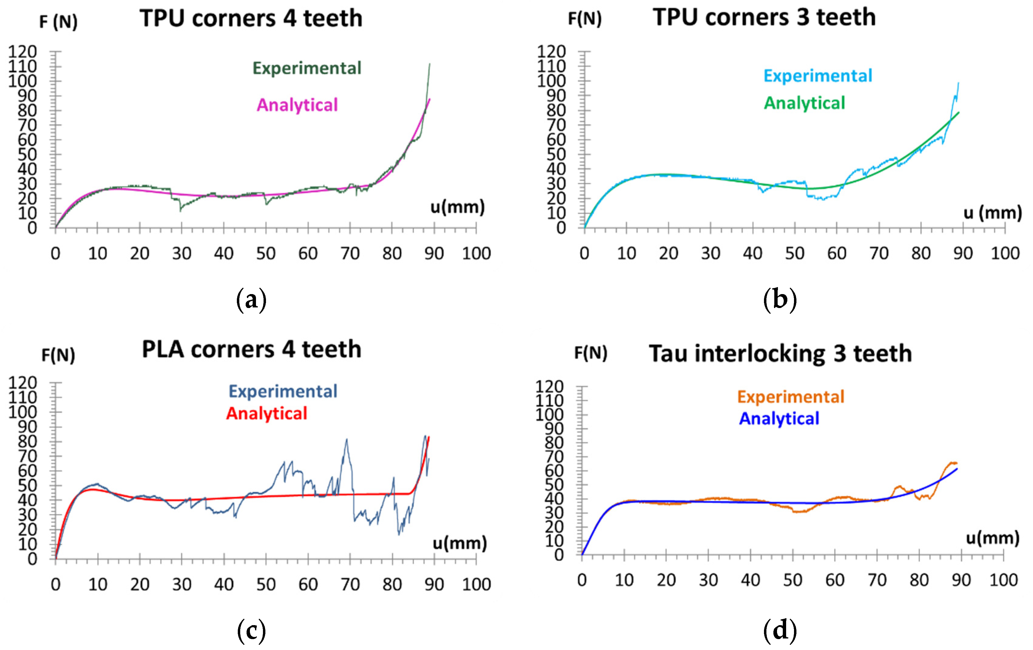
The refined analytical force–displacement model was fitted to the experimental data for all the honeycomb configurations, and the comparison between the proposed model and experimental curves is presented in
Figure 7.
Figure 7 demonstrates a strong agreement between the experimental results and the analytical model for the interlocking honeycomb configurations. The proposed formulation successfully fits the main characteristics of the response, including the initial stiffening, the development of the collapse regime, and the transition to densification. For the PLA-corners configuration, the model captures the initial stiffness and the general transition toward densification. However, larger deviations are observed in the plateau region. These deviations are attributed to the experimentally observed damage accumulation and structural integrity loss, which introduce localized failure effects not explicitly included in the analytical formulation. Τhe TPU-corners configurations are also represented satisfactorily, although minor deviations are observed in the transition between the initial and collapse regimes. The response in the plateau regime is captured with high fidelity, indicating that the underlying deformation mechanisms of the interlocking architecture are consistent with the physical assumptions of the model. Minor discrepancies observed near the transition from the initial regime to collapse can be explained by geometric variations and localized interfacial effects that are not explicitly taken into account in the analytical expression. Overall, the proposed model offers a reliable and physically interpretable description of the compressive response of the interlocking multi-material honeycomb structures, as confirmed by the strong agreement between the analytical and experimental results.
3.3. Comparative Analysis of Mechanical and Analytical Parameters
Table 2 summarizes the experimentally identified and analytically fitted model parameters, offering a numerical comparison of the effects of material distribution and deformation-oriented contribution and the interlocking-related effects for the examined honeycomb configurations. The PLA-corners configuration demonstrated the highest force level in the initial stage. While bending continues to be the primary mechanism controlling the overall response, the values of
and
indicate increased axial deformation in comparison to the other configurations. This is consistent with its experimentally high load-carrying capacity, although its post-yield structural integrity remains limited.
Among the teeth-based configurations, the TPU-corners three-teeth configuration revealed a more favorable response than the TPU-corners four-teeth case, confirming that increasing the number of teeth does not necessarily improve the global mechanical performance. Although both cases remain bending-dominated, the three-teeth design exhibits a higher plateau-related response and improved deformation stability, suggesting more effective stress redistribution and reduced sensitivity to local geometric or additive manufacturing imperfections. A plausible explanation is that the four-teeth geometry is more susceptible to FFF-induced manufacturing effects, including local dimensional inaccuracies, voids, imperfect inter-struts and interlayer bonding, and non-uniform material deposition. These defects can reduce the efficiency of load transfer across the interlocking region and promote local stress concentrations, thereby partially offsetting the expected benefit of the increased number of teeth. This interpretation is consistent with the experimentally observed response at large deformation levels.
In general, TPU-corners cases show larger values of Cb and lower values of Cα, suggesting a more noticeable bending-dominated reaction. Since the structure depends more on member bending than on a combined deformation mechanism, this reduces the overall load-carrying capacity even if it produces a stable and predictable deformation pattern. As a result, while both configurations function well, they fall short of the PLA-corners case’s mechanical performance. The densification displacement ud is comparatively constant in all configurations, indicating that the global geometry of the honeycomb structure, rather than the particular material arrangement or interfacial design, is principally responsible for controlling the commencement of densification. This discovery shows that all specimens undergo the transition to the compacted state at comparable deformation levels, despite variations in the collapse behavior.
The tau interlocking configuration exhibits the most clearly different interlocking parameters. In particular, the high value of indicates a strong interfacial engagement effect, while the lower value is consistent with reduced geometry-induced damage sensitivity compared with the other teeth-based designs. The fitted values of and further indicate that the tau architecture combines a relatively high collapse load with a strong densification response. Even though its peak force remains lower than that of the PLA-corners configuration, the tau interlocking case exhibits a more stable post-elastic evolution and preserves structural integrity more effectively at a large deformation. This makes the tau topology particularly advantageous when deformation tolerance and structural continuity are more critical than maximum peak load.
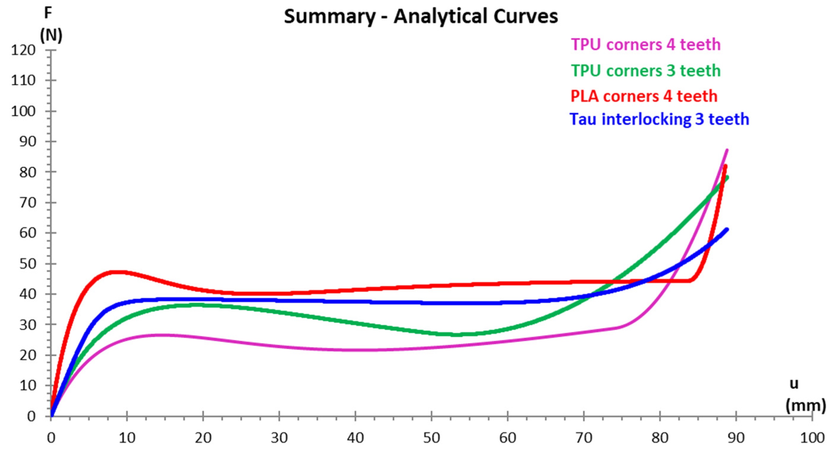
A comparison of the force–displacement curves for each of the configurations under investigation, as determined by the suggested analytical model, is shown in
Figure 8. The figure clearly illustrates the impact of material distribution and interlocking geometry on the overall structural performance by highlighting the variations in stiffness evolution, collapse behavior, and densification response between the various cases.
3.4. Interpretation of Deformation Mechanisms
Beam-lattice modeling was employed to further interpret the deformation mechanisms by separating the axial and bending contributions to the overall structural response. As evidenced by the comparatively large values of Cb in all configurations, the beam element approach verified that bending deformation is the predominant mechanism for the studied geometry. However, the increased value of Cα indicates an enhanced axial contribution in the PLA-corners configuration. This behavior is attributed to the placement of the stiffer PLA phase at the nodal regions, which reduces the local nodal deflection and allows for a slightly greater portion of the applied compressive load to be carried through axial deformation rather than only through bending of the struts. This partial increase in axial participation contributes to the improved mechanical performance observed in the experiments and increases the efficiency of load transfer.
On the other hand, despite their stable deformation behavior, the TPU-corners configurations remain strongly bending-dominated. Overall, the findings show that the mechanical response of the examined dual-material honeycomb structures is governed not only by a bending-dominated mechanism but also by the balance between axial and bending contributions, which is heavily impacted by the material distribution.
4. Discussion
The analyzed dual-material honeycomb architectures’ mechanical response is controlled by a combination of material distribution, interfacial geometry, and cell-level deformation mechanisms, as consistently shown by the experimental and analytical results. The expected behavior of elastic response, gradual collapse, and densification is present in all configurations, although the size and stability of these stages differ greatly according to how the materials are arranged.
The PLA-corners configuration exhibits the highest load-carrying capacity in terms of force, as the placement of PLA at the nodes locally reinforces the regions of maximum bending moment. However, once damage initiates, it becomes more extensive, as the structural integrity rapidly deteriorates when the deformation increases significantly. These findings are qualitatively consistent with another work [
19], which showed that softer dual-material combinations favor more stable deformation, whereas PLA/Nylon systems are more prone to premature interfacial failure. In the present study, the TPU/PLA interlocking joints similarly promote a bending-dominated but mechanically more stable response, with improved load transfer and delayed structural degradation. Furthermore, within an analytical study proposed by Huang et al. [
22], the improved behavior of the TPU/PLA interlocking joints observed in the present work may be interpreted as the result of a more favorable bending-controlled deformation mechanism and more efficient stress redistribution at the material interfaces.
In contrast, the TPU-corners configurations exhibit lower strength, as the critical nodal regions consist of the more compliant TPU. Among them, the three-teeth geometry demonstrates better performance compared to the four-teeth configuration, indicating that increased geometric complexity and overlap do not necessarily improve the global structural response and may increase sensitivity to local geometric or manufacturing imperfections.
The tau interlocking (three teeth) configuration exhibits the second-highest strength and a clearly superior post-elastic response. For deformation levels above approximately 50%, it maintains stable behavior, while the other configurations show pronounced fluctuations. At large deformation (≈95%), the tau configuration preserves the structural geometry more effectively than all other cases. The ranking in terms of structural integrity is tau interlocking (three teeth) and TPU corners (three teeth), followed by TPU corners (four teeth) and PLA corners (four teeth), which exhibit the most severe structural degradation and disintegration. It should be noted that the proposed analytical model has been validated for the specific honeycomb geometry, material combination, wall thickness, and cell dimensions examined in this study. Therefore, the fitted parameters and deformation coefficients should not be considered universal constants. Further validation across different cell numbers, wall thicknesses, side lengths, and specimen aspect ratios is required to assess the broader applicability of the model.
These results highlight that interlocking geometry plays a key role not only in load transfer but also in maintaining structural integrity under large deformation. The tau interlocking configuration provides the most stable post-elastic response and the best preservation of structural continuity, indicating that the geometry of the interlocking region can be more critical than peak force when deformation tolerance is required. This configuration allows the structure to deform steadily and gradually, suggesting the tau-shaped design is more effective in accommodating bending-dominated deformation and delaying localized structural failure.
5. Conclusions
In this work, the compressive behavior of dual-material honeycomb structures, with different material distributions, consisting of a combination of two materials (at the nodes and in the struts), and interlocking designs, was investigated. The results showed that the compressive behavior of dual-material honeycomb structures is primarily governed by bending deformation, with material distribution playing a key role in performance. The PLA-corners configuration provides the highest load-carrying capacity due to the reinforcement of critical bending regions and a more balanced axial–bending response. The TPU-corners configurations exhibit lower strength but maintain stable deformation, with the three-teeth design outperforming the four-teeth case, indicating that simpler interlocking geometries are more effective. The tau interlocking (three-teeth) configuration showed the best performance at large deformations. Beyond 50% strain, it maintains stable behavior, and at ≈95% deformation, it preserves its structural integrity more effectively than all other configurations. Although the proposed analytical model showed good agreement with the experimental results for the examined configurations, its validation is currently limited to the investigated honeycomb structures. Future work should extend the validation to different honeycomb sizes, wall thicknesses, side lengths, and aspect ratios in order to establish the generality of the model. Overall, the results show that peak load is controlled by material selection, whereas structural integrity and deformation stability at large deformations are primarily governed by interlocking design.




 ,
,