Article

Adaptive Torque Control for Process Optimization in Friction Stir Welding of Aluminum 6061-T6 Using a Horizontal 5-Axis CNC Machine

1
School of Engineering, Penn State University, Erie, PA 16563, USA
2
GROB Systems Inc., Bluffton, OH 45817, USA
*
Author to whom correspondence should be addressed.
J. Manuf. Mater. Process. 2025, 9(7), 232; https://doi.org/10.3390/jmmp9070232
Submission received: 29 May 2025 / Revised: 1 July 2025 / Accepted: 4 July 2025 / Published: 7 July 2025
(This article belongs to the Special Issue Innovative Approaches in Metal Forming and Joining Technologies)

Abstract

The research presented herein investigates the impact of axial force and feed rate in the Friction Stir Welding (FSW) of aluminum alloy 6061-T6 in a GROB G552 horizontal 5-axis CNC machine with adaptive torque control enabled. The purpose of this study is to further advance the performance and characteristics of FSW aluminum alloys in 5-axis CNCs, particularly in conjunction with adaptive torque control. The Taguchi and ANOVA methods were utilized to define parameter tables and analyze the resulting data. Optical microscopy and tensile tests were performed on the welded samples to evaluate weld quality. The results from this study provide clear evidence that axial force has a significant effect on tensile strength in FSW AA6061-T6. The maximum UTS found in this study, welded with an axial force of 9.4 kN, retained 69% tensile strength of the base material. Conversely, a decrease in strength and an increase in void formation was found at higher feed rates with this force. Ideal welds, with minimal defects across all feed rates, were performed with an axial force of 8.3 kN. A feed rate of 300 mm/min at this force resulted in a 67% base metal strength. These findings contribute to improving joint strength and application efficiency in FSW AA6061-T6 performed in a horizontal 5-axis CNC machine where adaptive torque control is enabled.
Keywords:
FSW; aluminum; 6061; 5-axis; CNC

1. Introduction

Friction Stir Welding is a solid-state joining process that was originally developed in 1991 at The Welding Institute in Cambridge, UK [1]. This process utilizes a rotating tool, plunged into a base material and traversed along a path at a specified speed. FSW has gained popularity recently as its use in industry has become more practical. Applications in the automotive, aerospace, marine, and rail industries have garnered interest for further research and the development of this process [2]. The ability to perform adjacent milling and joining of AA6061-T6 in a horizontal 5-axis CNC further expands the possibilities of FSW in manufacturing settings, which is the goal of this study. To accomplish acceptable welds on AA6061-T6, much higher axial forces are required than have previously been studied on a machine of this configuration. This study will determine the effects axial force and feed rate have on the final weld quality in a horizontal 5-axis CNC. The mechanical and microstructural effects of using adaptive torque control to monitor and regulate axial force will also be studied. Given the critical role of torque in determining weld quality, process stability, and tool wear, studies on FSW must provide a thorough analysis of torque control strategies, as these significantly influence the optimization and repeatability of the welding process [3].

1.1. Applications and Use of AA6061-T6

AA6061-T6 is widely used in industrial applications due to its high strength-to-weight ratio, weldability, and corrosion-resistant properties [4]. It is a key candidate for FSW in a 5-axis CNC as it is widely used in parts that require complex machining operations, followed by welding in a separate operation through processes such as MIG, TIG, laser, etc. As industries strive to improve the strength-to-weight ratio of load-bearing products, the use of aluminum alloys has continued to increase [5]. With the birth of aviation in 1903, aluminum naturally became a staple in aircraft structures and continues to be used in the aerospace industry today. Since its inception as Alloy61s in 1935, AA6061 has become one of the most extruded alloys in use [6]. The nominal composition of AA6061-T6 is shown in Table 1.

1.2. Five-Axis Machining

In 5-axis machining operations, the optimization of the tool path is used to improve the overall process efficiency. This requires manipulating the part to provide the ideal cutting orientation that will provide the best surface finish and prevent tool gouging [9]. Tool path optimization in 3-axis machining requires longer tools to be used in order to machine the sides of the part, while a 5-axis CNC allows the part to be rotated more optimally, so a shorter tool can be utilized to machine the sides. This is key in reducing vibrations, which help extend tool life and improve the surface finish as well [10]. The cost benefits of increasing tool life are apparent, while an improved surface provides opportunities for industrial sectors such as the medical, aerospace, and mold and die sectors that require higher surface finishes and tighter tolerances. To avoid the overheating of the cutting tool, cooling must also be considered. A loss of accuracy and tool life may occur if thermal input from machining of the part is not controlled [11]. For this reason, a cooling system is used to maintain a thermal steady state. The additional dynamic of placing the Z-axis horizontally in a 5-axis CNC, as opposed to vertically, opens up even more capabilities, such as upside-down machining, allowing contactless chip evacuation for improved surface finish [12]. The importance of surface finish and trim is particularly highlighted when machining parts to be welded, ensuring proper joint fit-up.

1.3. Previous Work on FSW 6061

When welding a heat-treatable alloy such as AA6061, thermal input must be controlled to ensure mechanical integrity is maintained. Heat created from friction is dissipated into the material, leading to lower hardness in the heat-affected zone (HAZ) and the thermo-mechanically affected zone (TMAZ) as compared to the stir zone (SZ) [13]. This reduction in hardness can be attributed to the Hall–Petch effect, which explains that larger grain sizes will result in lower hardness [14]. When the heat is sufficient enough to lose the temper properties of AA6061-T6, the material, in essence, becomes annealed [15]. The effects of annealing 6061 were studied by Nasir et al. and found that a Brinell hardness of “as-received” AA6061 dropped from an average of 94.6 to 90 HB when annealed [16]. Research conducted by Hussein et al. agrees with these findings and also notes that the yield stress of AA6061 in the annealed condition is 42% lower than the T6 condition [17]. In a study identifying optimal temperature ranges when welding AA6082-T6 and AA5083-H111, Abboud et al. found that a temperature equivalent to 65% of the solidus temperature of the base material should be maintained at the weld for adequate weld quality and freedom from defects such as voids [18]. The main factor in a loss of strength, where excessive heat is input into the material, is the dissolution of β′-phase precipitates that are key to the mechanical strength of AA6061-T6 [19]. For these reasons, in conventional FSW of AA6061-T6, the level of heat input must be controlled by optimized process parameters.
Some examples of FSW process parameters are the feed rate, the axial force, and the tool rotation speed. These parameters control the speed at which the tool travels through the weld seam, the force on the tool at the workpiece, and the rate at which the tool spins while welding, respectively. The effects that these parameters have on mechanical properties have been widely studied and continue to be optimized for alloys such as AA6061-T6. In a study by Sefene et al., the tool rotation speed, the feed rate, and the tool pin profile were assessed for their effects on the mechanical properties of 5 mm thick AA6061-T6 [20]. It was found that a feed rate of 30 mm/min had a higher UTS and hardness than the 40 mm/min and 50 mm/min feed rates. The feed rates were also found to have the greatest effect on the level of heat generation in the weld. The tool rotational speed can play a significant role in the hardness of the weld at speeds of 2000 rpm and higher [21]. In a study by Zhang et al., higher tool rotation speeds were found to enlarge grains in 6 mm-thick AA6061-T4. The weld nugget size grew as the tool rotation speed increased. Adversely, the hardness decreased when the tool rotation speed exceeded 1000 rpm, and the heat generated by the tool increased greatly above 2000 rpm.
The role of the FSW tool is to generate heat in the weld zone and plastically deform the base materials into a solid-state bond. The shoulder generates frictional heat through sliding and sticking forces, while the pin mixes the material around it. A balance of heat and mixing defines the quality and integrity of the weld, as most defects are due to a lack of material flow or excessive heat inducing grain growth in the stir zone [14]. The effects of tool shoulder geometry on FSW joint strength have been previously studied. In a study on the effects of shoulder geometry on FSW AA6061, Trueba et al. note that cavitation along the centerline of the weld, due to poor material flow, is directly related to shoulder geometry. Shoulder geometry was found to not only play a role in weld strength but also to improve surface finish when the shoulder had a raised spiral face [22]. A nominally flat surface on the base metal has also been found to reduce weld flash. This is noted by Lader et al. in another study where weld flash was exacerbated by the additional heat created from excess material built up around the shoulder [23]. Controlling the heat generated during FSW can also be managed by way of internal and/or external cooling. Processes such as Underwater Friction Stir Welding (UFSW), where the surrounding water acts as a cooling agent, reducing heat input into the material, can improve the microstructure and tensile strength of the weld as compared to conventional FSW [24]. In recent years, the optimization of FSW processes has received increasing attention, encompassing various enhancements such as liquid CO2-assisted cooling FSW [25], the combined use of flowing coolants with ultrasonic vibrations [26], UFSW [24,27], Stationary Shoulder FSW (SSFSW) [28,29], Level-Compensation FSW (LCFSW) [30], Vertical Compensation FSW (VCFSW) [31], and force control in FSW [32]. Processes such as UFSW and SSFSW aid in reducing heat input, while VCFSW has been found to improve joint quality where gaps may be present. Testing with LCFSW was found to improve ductility and joint strength in AA6061-T6. Force and temperature control were achieved by adjusting the tool rotation speed and the plunge depth in FSW AA6061-T6 to AA7075-T6 [32]. Improved welds were made by monitoring and controlling both variables when compared to welds made by conventional FSW. However, the system was limited by low updating frequency due to using an external system for monitoring and controlling feedback.

1.4. Benefits of FSW in 5-Axis CNC

Required and resulting forces during FSW limit the flexibility of application to machines that can withstand several kilonewtons of force across the machine axes. Trimble et al. note that the forces generated from FSW are considerably larger than the forces generated during milling operations [33]. However, harmonic frequencies imposed on the machine tend to be lower in FSW compared to milling processes, notably due to the absence of cutting teeth on the FSW tool, which leads to smoother lobed sinusoidal waves [34]. Three-axis CNCs, or robotic gantry systems, with fewer axes and simpler kinematics, are often utilized for FSW, but limit welding to be performed in the flat planar orientation and limit the geometry of parts able to be machined as well [35]. In a study on 5-axis CNC development, Breaz et al. noted the benefit of 5-axis kinematics that allow for simultaneous motion in all five axes. In this way, translational and rotational cuts can be performed on much more complex parts than are able to be performed on a 3-axis CNC [36]. This is mostly critical when machining parts to be friction stir welded and preparing the joint before welding. In FSW, part fit-up and gap management are paramount in ensuring weld integrity [37]. In a study by Inada et al. the effects of butt joint gap distances were tested on 5 mm nominal thickness AA1050-H24. Joint gaps over 20% material thickness caused microscopic internal defects and the deterioration of joint strength [38].
This research examines the mechanical and microstructural effects of AA6061-T6 FSW in a horizontal 5-axis CNC where adaptive torque control is utilized as a variable for parameter optimization. Adaptive torque control offers a more suitable method for maintaining constant axial force at the tool than conventional positional control, along with more favorable joint attributes [39]. While different methods of torque and force control have been investigated previously [32,39], this study aims to address the gap in joint strength optimization where the axial force, by way of adaptive control, and the feed rate are variables in the optimization of FSW AA6061-T6. The implications of continuous adaptive force control under varied feed rates and their relationship to joint strength in FSW AA6061-T6 are not widely studied to the best of the authors’ knowledge. Further developments can be made with the results from this study serving as a foundation for process optimization in future tests.

2. Testing Methodology

A methodical approach was used to define the experimental parameters in order to set up a procedure for testing and determining the results of this experiment. The AA60601-T6 weld samples, with a nominal thickness of 6.35 mm, were laser cut to the dimensions of 100 × 200 mm2 using a Trumpf TruFlow 4 kW CO2 laser. The weld sample dimensions, in mm, are shown in Figure 1. Holes were also laser cut into the plates for fastening to an aluminum backing plate for welding in the butt-joint configuration. The FSW tool used had a smooth, cylindrical, tapered pin profile with a 19 mm shoulder and was machined from AISI A2 tool steel. The FSW pin had a length of 5 mm with a major diameter of 5.5 mm, tapering down to 3 mm at the tip. Based on the ideal parameters found in previous research on FSW AA3003-H14 in a horizontal 5-axis CNC, a tool rotation speed of 1200 rpm was used for all welds in this study [40]. The parameter table for this experiment is shown in Table 2. Axial forces of 7.3, 8.3, and 9.4 kN and feed rates of 100, 200, and 300 mm/min were tested. Adaptive torque control was used to maintain a constant axial force while welding. The axial force was calculated based on motor torque in the Z-axis. Increments of 5 Nm of motor torque equated to 1.04 kN of axial force enacted onto the FSW tool. This explains the force range of 7.3, 8.3, and 9.4 kN. Initial tests at lower force ranges did not yield successful welds. Feed rates were selected based on previous research on FSW AA3003-H14 in a horizontal 5-axis CNC machine [40]. The purpose of controlling force, as opposed to position control in the Z-direction, is to use the adaptive control of tool position to maintain constant pressure on the FSW tool. The advantage of this is noted by Safeen et al. in a study that found a larger acceptance range among various weld parameters with force control due to the adaptability to overcome variations in material form, specifically in thinner material [41]. Additionally, Longhurst states that volumetric defects are reduced when using force control, as opposed to position control [39].
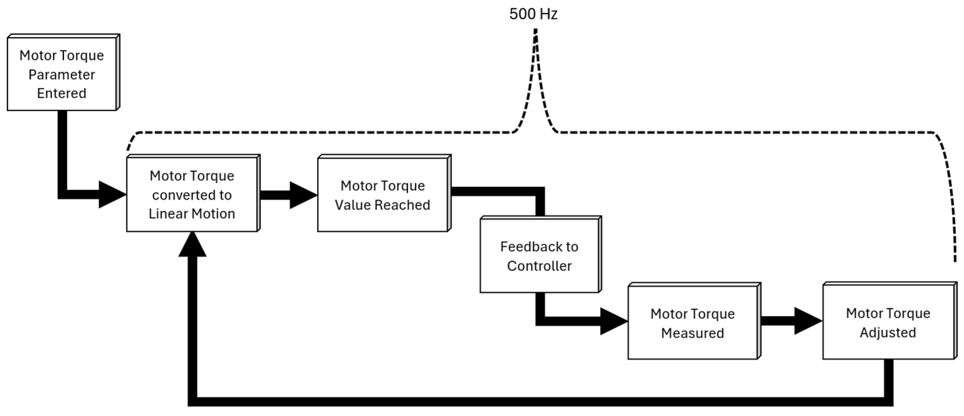
The adaptive torque control system used in this study measured torque on the Z-axis motor, in relation to a pre-defined parameter, to monitor and control axial force on the FSW tool. A diagram of the Z-axis components in the CNC machine configuration used in this study is shown in Figure 2. In this configuration, the Z-axis motor controlled the Z-axis ball screw which drove the Z-axis and attached spindle either forward in the positive (+) direction or backwards in the negative (−) direction. The ball screw pitch and motor torque were used to calculate the axial force at the tool. The ball screw pitch was a constant based on machine configuration, while the motor torque was an input parameter. A flow chart of the adaptive torque control process is shown in Figure 3. The motor torque (value in Nm) was entered as an input parameter into the machine controller. The torque on the Z-axis motor was monitored while driving the Z-axis carriage along with the spindle by way of the Z-axis ball screw, as it approached the pre-defined motor torque value. Variations in the motor torque were measured and adjusted at a frequency of 500 Hz. By monitoring and adjusting the torque on the Z-axis motor, the axial force at the tool was controlled and maintained throughout the welding process to within 2.3% of the programmed value.
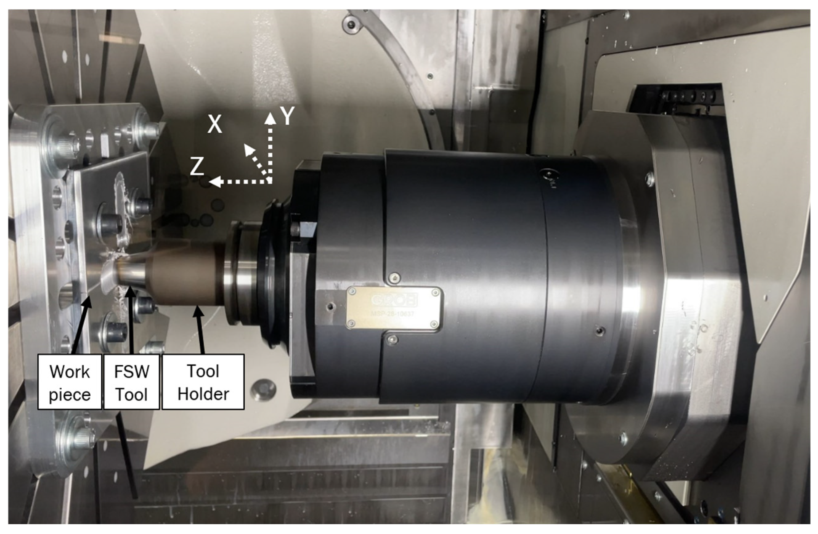
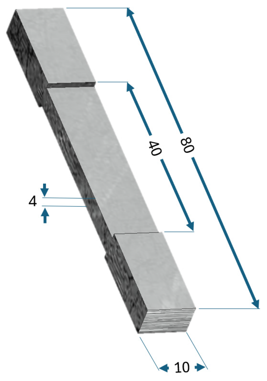
The workpiece setup in the machine is shown in Figure 4, where the FSW tool and the tool holder can be seen welding in the horizontal butt position. Welding was performed in a GROB G552 horizontal 5-axis CNC machine with a Siemens 840D controller. In a horizontal 5-axis CNC of this configuration, the feed rate, or the weld direction, is in the +X direction while axial plunge is in the +Z direction in relation to the three-dimensional Cartesian plane. Tensile specimens were cut from the workpiece and machined to a reduced thickness of 4 mm at the zone of welding, as seen in Figure 5. Non-standard geometries were used for the tensile specimens in this study. Testing was part of an industrial request that did not require ASTM E8M standard specimens to be used. Due to the presence of an unwelded zone below the weld pin, the tensile specimens were machined to a nominal thickness of 4 mm to validate the joint strength of only the welded material. Two tensile samples were cut for each weld set in this study. The samples prepared for testing are shown in Figure 6. Weld sample numbers are labeled below each sample. A complete list of weld conditions for each sample # is shown in Table 3.

3. Results

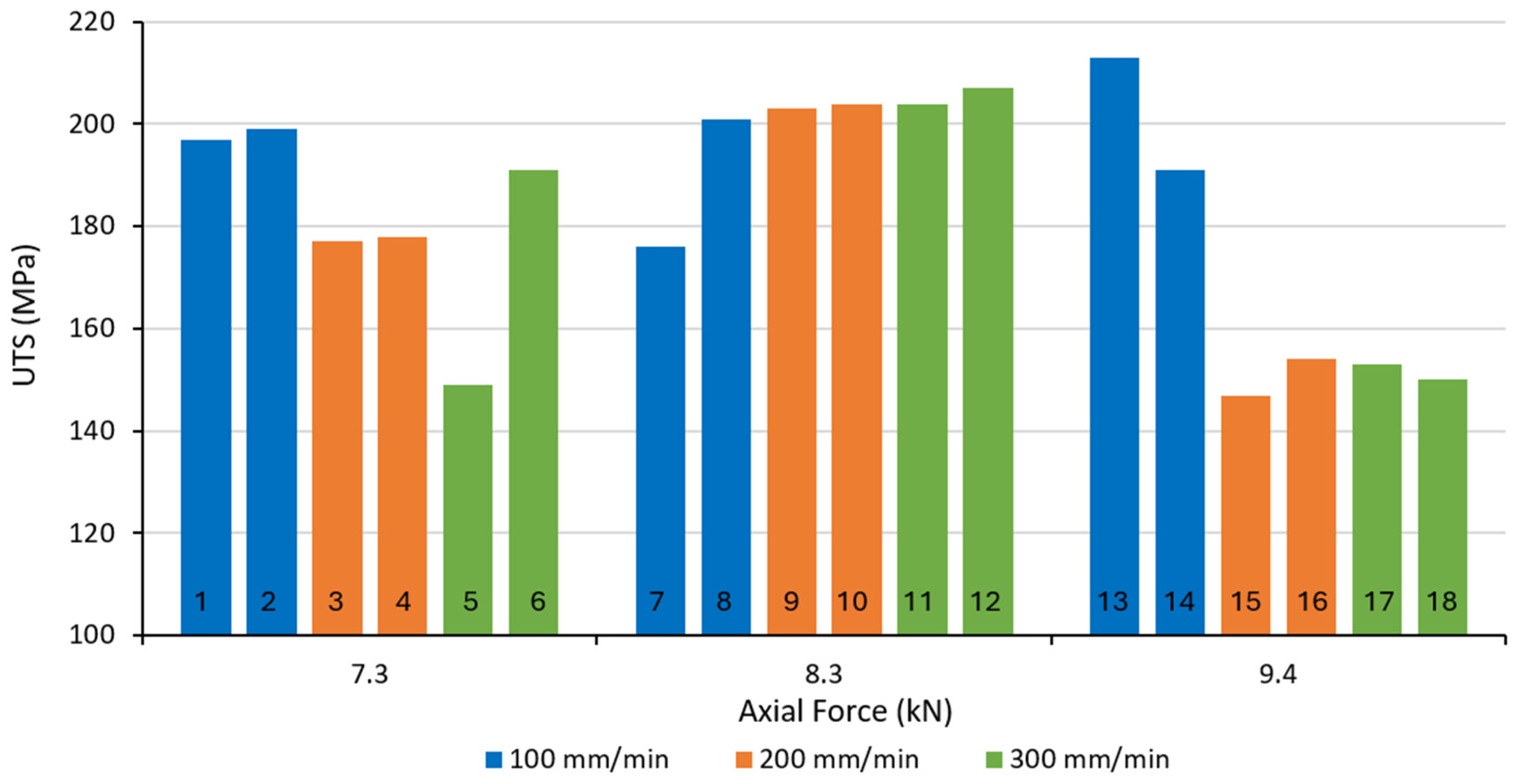
The specimens were tensile tested to failure using a Zwick-Roell 100 kN ProLine test frame with a Zwick/Roell Type 8406 50 kN load cell used in conjunction with Zwick/Roell testXpert® III software. No signal conditioning or amplification was used with this software in these tests. The specimens were secured center and square in the tensile stand jaws. Weld samples are shown after tensile testing in Figure 7, with a white dotted line representing the original center of the weld seam. Both brittle and ductile failures were observed in the destructive tests. The tensile results for all of the samples in this study are shown in Figure 8. Weld sample #s are labeled for each result. On average, the welds performed at 8.3 kN axial force had a higher tensile strength than other axial forces tested in this experiment. These results show an improved UTS compared to previous work on the conventional FSW of AA6061-T6 [15,22,42]. Joint strength in VCFSW 4 mm AA6061-T6 was found to be comparable to the results from this study [43]. Specimens exhibiting ductile failures breaking outside of the weld zone had, on average, an 18% higher UTS than specimens with brittle fractures within the weld. Kalinenko et al. explain this phenomenon in FSW AA6061-T6 with regard to continuous recrystallization and grain refinement under the FSW tool. Higher levels of continuous recrystallization and grain refinement in the SZ are aspects of FSW that have been found to increase UTS. Additionally, the partial dissolution of β′ precipitates and annealing in the TMAZ have been found to retain up to 75% ductility in FSW AA6061-T6 [44,45]. In these studies, samples with a lower tensile strength were attributed to brittle fracture behavior due to crack propagation within the weld. In this study, parametric settings yielding higher ductility in tensile failures were found with a 7.3 kN axial force at lower feed rates and an 8.3 kN axial force at higher feed rates. However, higher feed rates welded with a 9.4 kN axial force exhibited a decrease in both ductility and UTS. It should be noted that with a 9.4 kN axial force at a lower feed rate, tensile strength was comparable to a 8.3 kN axial force at higher feed rates. When comparing the average UTS of the samples for each weld parameter, a similar trend can be seen in Figure 9. The Standard Deviation (σ) for each parameter is also plotted by the black line along the UTS values. It can be seen that while an axial force of 9.4 kN with a feed rate of 100 mm/min had higher UTS than most other weld parameters, the σ was also higher. Conversely, the welds performed with an axial force of 8.3 kN and 300 mm/min averaged a higher tensile strength with a drastically lower σ.
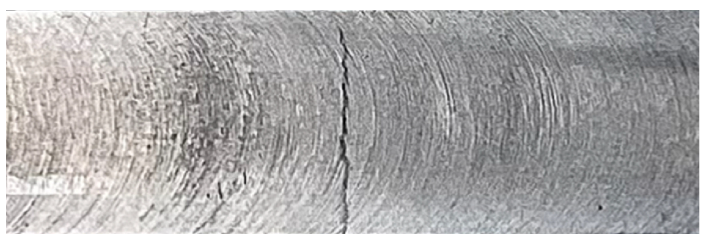
The lowest UTS found was sample #15, welded with a 9.4 kN axial force at a 200 mm/min feed rate and exhibiting a UTS of 147 MPa. Macroscopic cracks through the weld seam, shown in Figure 10, were observed before destructive testing in this specimen. The crack through the center of the weld seam created a stress riser, which led to brittle fracture propagation through the weld during tensile testing. Although this is a defect in the weld, the UTS was not outside of the data boundaries enough to be considered an outlier. This was the only sample with an external crack observed before destructive testing.
Specimens welded with 8.3 and 9.4 kN axial forces were prepared, cut, and polished before etching in sodium hydroxide for optical microscopy (OM). Microscopic imaging was performed with a Carl Zeiss Axio Imager Z2M. Samples welded with 7.3 kN axial force were tensile tested preemptively to micrographs, as this study was part of an industrial request for information on UTS. With the goal of achieving the highest UTS, the first samples welded with a 7.3 kN axial force were destroyed before OM was performed. Figure 11 shows a microscopic view of samples #14–18 before destructive testing (above) and after destruction (below). Voids can be seen, circled in red, along the advancing side of the welds. Etched welds are outlined by the yellow dotted line. Brittle fractures occurred in samples #14–18, mainly due to void formation within the weld root along the advancing side. Voids formed in all samples welded with a 9.4 kN axial force, which could indicate that a higher axial force has adverse effects on solid-state mixing. This could be in part due to excessive material flow causing voids under the pin, as also previously noted by Longhurst [39]. Manickam et al. also state, in an extensive review on the implications of process parameters in FSW AA6061-T6, that excessive mixing and material flow can cause tunneling and voids [46]. The location of the voids at the base of the pin is likely due to excessive heating and mixing at the higher axial force range. Trueba et al. note that the presence of voids, or lack thereof, has the greatest influence on joint strength and ductility [47]. Also visible in the microscopic images is the presence of a lazy “S”, or kissing bond, in the weld nugget. The lazy “S” defect is found when oxides from the surface of the aluminum are mixed into the weld, preventing a solid-state bond from forming along the oxidation layer [48].
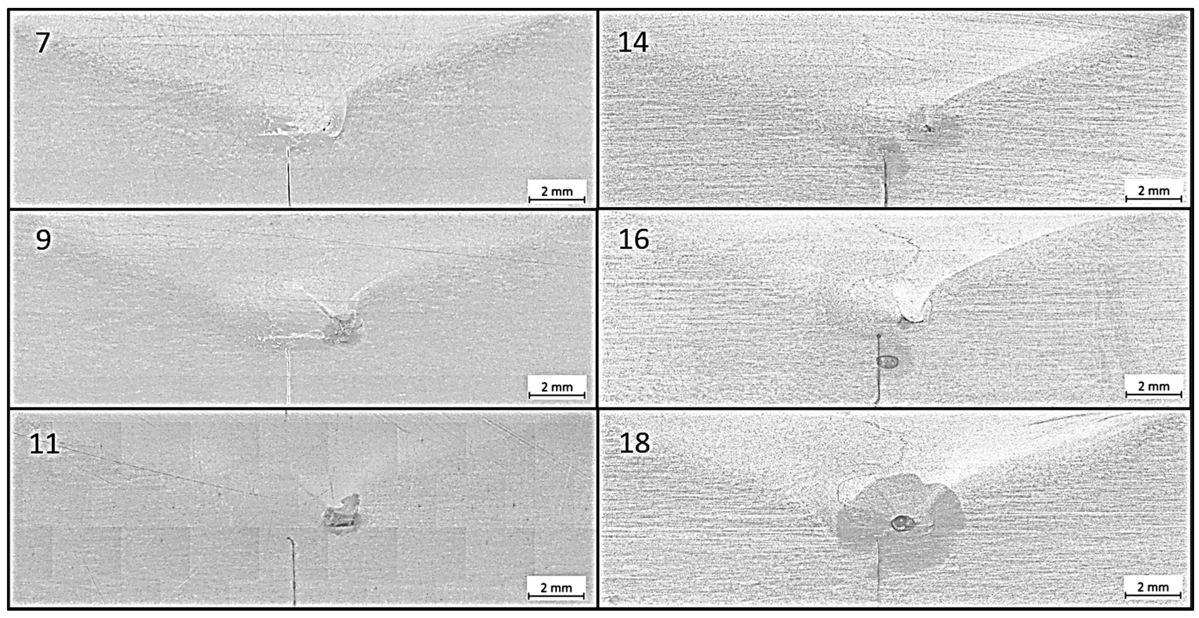
A comparison of the before and after destruction images shows that fractures occurred along and through the lazy “S” but do not explicitly follow the “S” path. An enlarged image of the lazy “S” in sample 18 is shown in Figure 12. The lazy “S” also appears to become more prominent as the feed rate increases. This phenomenon was observed by Zhang et al., whereby increasing the feed rate, and in turn decreasing the heat input, caused a more pronounced lazy “S” defect [49,50]. Voids in the root of the SZ were also found to form in welds conducted with higher feed rates, correlating with the results found in this study as well. Higher feed rates resulted in lower plastic deformations and higher concentrations of the surface oxide within the weld. Meanwhile, lower feed rates, with higher levels of plastic deformation per unit length, reduced the continuity of the lazy “S”. Areas with unbonded material, such as along the lazy “S” continuity, have been found to drive crack transmission during destructive testing [51]. As the tensile samples experienced vertical load, the fracture path began at the voids in the root and propagated along and through the lazy “S” defect. Interestingly, this defect does not appear to be as prevalent in samples welded at 8.3 kN, as can be seen in Figure 13. Micrographs of welds performed at 7.3 kN were not collected in this study, as previously mentioned.

Taguchi Analysis/ANOVA

A Taguchi Analysis was run on the effects of axial force and the feed rate on UTS using the Minitab 21.1 software. The analysis included three levels of an orthogonal array across two factors (axial force/feed rate). The signal-to-noise ratio was plotted using a “Larger-is-better” formula for the UTS, as shown in Equation (1), where y is the UTS, and i is the nth test. Axial force had a greater influence on the UTS than the feed rate, as can be seen by the rank in Table 4. The rank is an indication of which variable had the greatest effect on the results. In this study, the feed rate had a smaller difference, or delta, between max and min values than axial force across the S/N ratios and means, determining that the amount of variation in the UTS was lower due to changes in the feed rate than from axial force. Additionally, the F-values for axial force and the feed rate are 4.17 and 2.23, respectively, showing greater effects on the UTS due to changes from axial force. F-values calculated from the ANOVA test explain which variable had a more significant effect on the results. This conclusion can be further delineated in the ANOVA results for UTS in Table 5, where the p-value for axial force is lower than the alpha of 0.05. A p-value less than the predetermined alpha of 0.05 denotes significance in the results caused by changes to the variable being measured.
S N L B = 10 log 10 1 n i = 1 n 1 y i 2
Equation (1): Larger-is-better formula for UTS S/N ratio.
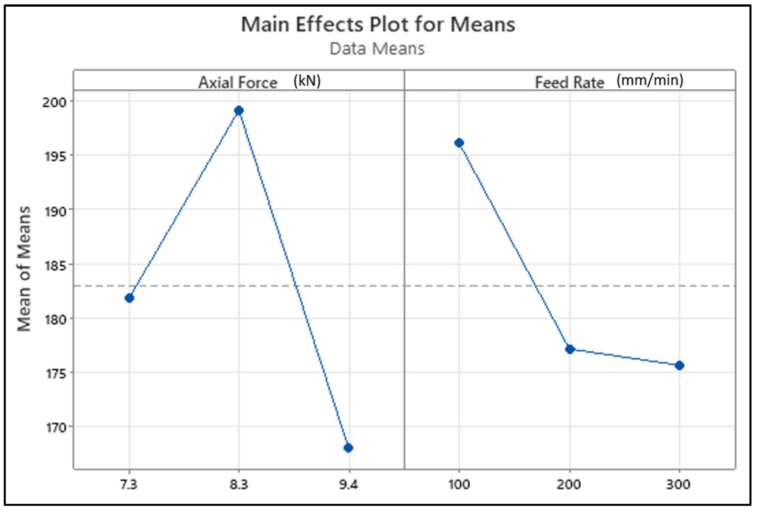
The Main Effects Plot for Means of each variable in this study can be seen in Figure 14. The Main Effects Plot for Means displays the average UTS across each variable and how changes to each variable affected the results. It can be seen that welds performed with an 8.3 kN axial force had the highest mean tensile strength, while a 9.4 kN axial force had the lowest. This phenomenon agrees with studies conducted by Ramamoorthi et al., where an increase in axial force from ideal parameter settings by 1 kN exhibited a decrease in tensile and bending strength of 6 mm AA5086/AA6063 FSW samples [52]. Additionally, Sreenivas et al. noted similar results in FSW 6 mm AA6082-T6, where a decrease in UTS was found when the axial force was increased by 1 kN from ideal parameters [53]. While the individual sample with the highest UTS was welded at 100 mm/min with a 9.4 kN force, higher levels of variation occurred at this force range. This was due to the presence of defects within the weld root, which decreased the UTS. The lazy “S” and voids in all samples welded at 9.4 kN resulted in a reduction in tensile strength at this axial force. Brittle fractures occurred in the SZ in samples with voids, which agrees with findings in the literature [44,45].

4. Conclusions

In this study, AA6061-T6 was FSW in a horizontal 5-axis CNC utilizing adaptive torque monitoring and control. It was found that changes made to axial force had a greater influence on tensile strength than changes to the feed rate. Welds performed with an 8.3 kN axial force had the highest UTS on average across all other axial force ranges. The presence of Lazy “S” defects and voids in welds performed with the highest axial force of 9.4 kN caused a 15% reduction in tensile strength compared to welds performed with an 8.3 kN axial force. The optimum settings found in this study were welded with an 8.3 kN axial force and a 300 mm/min feed rate. Both brittle and ductile failures occurred during destructive testing, with ductile failures yielding 18% higher tensile strength than samples exhibiting brittle fractures. These findings will contribute to continued research in a horizontal 5-axis CNC where adaptive torque control is enabled.
Key points from the work presented herein are listed below:
  • The optimal parameters yielding the highest UTS with the fewest defects were welded with an 8.3 kN axial force at a 300 mm/min feed rate.
  • A total of 67% of the base metal tensile strength was retained.
  • Welds performed with higher axial force caused voids due to excessive heating and mixing under the FSW pin.
  • Void creation and tunneling led to a decrease in UTS.
  • Lazy “S” defects were found in micrographs across all welds performed with a 9.4 kN axial force.
  • Higher feed rates increased the presence of the Lazy “S.”
  • Taguchi analysis showed axial force had a greater effect on UTS than feed rate.

5. Future Work

Future work will involve investigations into FSW AA6061-T6 and dissimilar additively manufactured alloys.

Author Contributions

Conceptualization, A.C. and I.R.; methodology, A.C. and I.R.; software, A.C.; validation, I.R. and A.C.; formal analysis, A.C. and I.R.; investigation, A.C. and I.R.; resources, A.C. and I.R.; data curation, A.C.; writing—original draft preparation, A.C. and I.R.; writing—review and editing, A.C. and I.R.; visualization, A.C. and I.R.; supervision, I.R.; project administration, A.C. and I.R.; funding acquisition, A.C. and I.R. All authors have read and agreed to the published version of the manuscript.

Funding

This research received no external funding.

Data Availability Statement

The original contributions presented in this study are included in the article. Further inquiries can be directed to the corresponding author.

Acknowledgments

The authors would like to thank colleagues of GROB Systems Inc., Doug Lieurance and Russell Cooper, for their help in programming and performing the welds for this research. An additional thanks to Brian Recker and Jacob Popham, also of GROB Systems Inc., for their assistance and insight into mechanical testing and microscopic imaging.

Conflicts of Interest

Authors Austin Clark was employed by GROB Systems Inc. The remaining authors declare that the research was conducted in the absence of any commercial or financial relationships that could be construed as a potential conflict of interest.

References

  1. Thomas, W.M. Friction Stir Welding—Process Developments and Variant Techniques; The SME Summit: Oconomowoc, WI, USA, 2005; pp. 1–19. [Google Scholar]
  2. Kallee, S.W. Industrial Applications of Friction Stir Welding. In Friction Stir Welding; Elsevier: Amsterdam, The Netherlands, 2010; pp. 118–163. [Google Scholar] [CrossRef]
  3. Belalia, S.E.; Serier, M.; Al-Sabur, R. Parametric Analysis for Torque Prediction in Friction Stir Welding Using Machine Learning and Shapley Additive Explanations. J. Comput. Appl. Mech. 2024, 55, 113–124. [Google Scholar] [CrossRef]
  4. Alcoa Engineered Products. Alloy 6061 [Engineering]. Aluminum 6061-T6; 6061-T651. Available online: https://sites.astro.caltech.edu/sedm/_downloads/4c62586a69bdc57ca49a938a3e3fc082/Extruded_Alloy_6061.pdf (accessed on 18 December 2024).
  5. Nappi, D.C. The Global Aluminium Industry 40 Years from 1972 (No. R47294; p. 22). 2022. Available online: http://large.stanford.edu/courses/2016/ph240/mclaughlin1/docs/nappi.pdf (accessed on 18 December 2024).
  6. International Aluminum Institute. 50 Moments. The Key Milestones in the Development of Today’s Modern Aluminium Industry. 2022. Available online: https://international-aluminium.org/wp-content/uploads/2022/12/50-Moments.pdf (accessed on 5 January 2025).
  7. Aerospace Specification Metals Inc. Aluminum 6061-T6; 6061-T651. 2000. Available online: https://asm.matweb.com/search/SpecificMaterial.asp?bassnum=ma6061t6 (accessed on 31 January 2025).
  8. Industrial Metal Service. Aluminum 6061 Material Properties. 2024. Available online: https://industrialmetalservice.com/metal-university/aluminum-6061-material-properties (accessed on 29 April 2025).
  9. Yuan, C.; Mi, Z.; Jia, X.; Lin, F.; Shen, L. Tool Orientation Optimization and Path Planning for 5-Axis Machining. J. Syst. Sci. Complex. 2021, 34, 83–106. [Google Scholar] [CrossRef]
  10. Heidenheim GmbH. Accuracy in 5-Axis Machining [Technical Information]. Influence of Position Measurement on Accuracy in 5-Axis Machining. September 2011. Available online: https://www.heidenhain.de/fileadmin/pdf/en/01_Products/Technische_Dokumentation/TI_Influence_of_Position_Measurement_on_Accuracy_5-Axis_Machining_ID895283_en.pdf (accessed on 23 January 2025).
  11. Wang, Y. Design and Development of a Five-Axis Machine Tool with High Accuracy, Stiffness and Efficiency for Aero-engine Casing Manufacturing. Chin. J. Aeronaut. 2022, 35, 485–496. [Google Scholar] [CrossRef]
  12. ZTL. Choosing the Right Milling Machine [Technical]. A Comprehensive Guide to Horizontal Milling vs. Vertical Milling. 8 November 2023. Available online: https://www.zintilon.com/blog/horizontal-vs-vertical-milling/ (accessed on 28 March 2025).
  13. Rao, C.M.; Rao, K.M. Evolution of Microstructure and Hardness of Aluminium 6061 after Friction Stir Welding. Int. J. Theor. Appl. Mech. 2017, 12, 405–410. [Google Scholar]
  14. Patil, S.; Nagamadhu, M.; Malyadri, T. A Critical Review on Microstructure and Hardness of Aluminum Alloy 6061 Joints Obtained by Friction Stir Welding-Past, Present, and its Prospects. Mater. Today Proc. 2023, 82, 75–78. [Google Scholar] [CrossRef]
  15. Abdullah, A.M. Mechanical Properties of AA 6061-T6 Aluminum Alloy Friction Stir Welds. J. Eng. 2015, 21, 52–61. [Google Scholar] [CrossRef]
  16. Zaiedah Nasir, N.; Mohd Daud, M.A.; Selamat, M.Z.; Rivai, A.; Dhar Malingam, S. The Effect of Heat Treatment on Fatigue and Mechanical Properties of 6061 Aluminium Alloy. Appl. Mech. Mater. 2014, 699, 227–232. [Google Scholar] [CrossRef]
  17. Hussein, S.G.; Al-Shammari, M.A.; Takhakh, A.M.; Al-Waily, M. Effect of Heat Treatment on Mechanical and Vibration Properties for 6061 and 2024 Aluminum Alloys. J. Mech. Eng. Res. Dev. 2020, 43, 48–66. [Google Scholar]
  18. Abboud, M.; Dubourg, L.; Racineux, G.; Kerbrat, O. Experimental Methodology to Identify Optimal Friction Stir Welding Parameters Based on Temperature Measurement. J. Manuf. Mater. Process. 2024, 8, 137. [Google Scholar] [CrossRef]
  19. Ogunsemi, B.T.; Abioye, T.E.; Ogedengbe, T.I.; Zuhailawati, H. A Review of Various Improvement Strategies for Joint Quality of AA 6061-T6 Friction Stir Weldments. J. Mater. Res. Technol. 2021, 11, 1061–1089. [Google Scholar] [CrossRef]
  20. Sefene, E.M.; Tsai, Y.-H.; Jamil, M.; Jatti, V.S.; Mishra, A.; AsmareTsegaw, A.; Costa, E.C. A Multi-Criterion Optimization of Mechanical Properties and Sustainability Performance in Friction Stir Welding of 6061-T6 AA. Mater. Today Commun. 2023, 36, 106838. [Google Scholar] [CrossRef]
  21. Zhang, H.J.; Sun, S.L.; Liu, H.J.; Zhu, Z.; Wang, Y.L. Characteristic and Mechanism of Nugget Performance Evolution With Rotation Speed for High-Rotation-Speed Friction Stir Welded 6061 Aluminum Alloy. J. Manuf. Process. 2020, 60, 544–552. [Google Scholar] [CrossRef]
  22. Trueba, L.; Heredia, G.; Rybicki, D.; Johannes, L.B. Effect of Tool Shoulder Features on Defects and Tensile Properties of Friction Stir Welded Aluminum 6061-T6. J. Mater. Process. Technol. 2015, 219, 271–277. [Google Scholar] [CrossRef]
  23. Lader, S.K.; Baruah, M.; Ballav, R.; Bag, S. Recent Developments in Friction Stir Welding Tools for Weld Bead Defects Minimization—A Review. Soldag. Inspeção 2023, 28, e2806. [Google Scholar] [CrossRef]
  24. Nishant; Jha, S.K.; Prakash, P. Effect of Tool Rotation Speed on Microstructure and Mechanical Properties of Underwater Friction Stir Welding 6061 Aluminium Alloy. Mater. Today Proc. 2023, 91, 9–13. [Google Scholar] [CrossRef]
  25. Liu, X.C.; Li, W.T.; Zhou, Y.Q.; Li, Y.Z.; Pei, X.J.; Shen, Z.K.; Wang, Q.H. Multiple Effects of Forced Cooling on Joint Quality in Coolant-Assisted Friction Stir Welding. J. Mater. Res. Technol. 2023, 25, 4264–4276. [Google Scholar] [CrossRef]
  26. Barooni, O.; Abbasi, M.; Givi, M.; Bagheri, B. New Method to Improve the Microstructure and Mechanical Properties of Joint Obtained using FSW. Int. J. Adv. Manuf. Technol. 2017, 93, 4371–4378. [Google Scholar] [CrossRef]
  27. Khalaf, H.I.; Al-Sabur, R.; Abdullah, M.E.; Kubit, A.; Derazkola, H.A. Effects of Underwater Friction Stir Welding Heat Generation on Residual Stress of AA6068-T6 Aluminum Alloy. Materials 2022, 15, 2223. [Google Scholar] [CrossRef]
  28. Ahmed, M.M.Z.; El-Sayed Seleman, M.M.; Fydrych, D.; Çam, G. Friction Stir Welding of Aluminum in the Aerospace Industry: The Current Progress and State-of-the-Art Review. Materials 2023, 16, 2971. [Google Scholar] [CrossRef]
  29. Sun, Z.; Yang, X.; Li, D.; Cui, L. The Local Strength and Toughness for Stationary Shoulder Friction Stir Weld on AA6061-T6 Alloy. Mater. Charact. 2016, 111, 114–121. [Google Scholar] [CrossRef]
  30. Wen, Q.; Yue, Y.; Ji, S.; Li, Z.; Gao, S. Effect of Welding Speeds on Mechanical Properties of Level Compensation Friction Stir Welded 6061-T6 Aluminum Alloy. High Temp. Mater. Process. 2016, 35, 375–379. [Google Scholar] [CrossRef]
  31. Abu-Okail, M.; Mahmoud, T.S.; Abu-Oqail, A. Improving Microstructural and Mechanical Properties of AA2024 Base Metal by Adding Reinforced Strip Width of AA7075 via Vertical Compensation Friction Stir Welding Technique. J. Fail. Anal. Prev. 2020, 20, 184–196. [Google Scholar] [CrossRef]
  32. Fehrenbacher, A.; Smith, C.B.; Duffie, N.A.; Ferrier, N.J.; Pfefferkorn, F.E.; Zinn, M.R. Combined Temperature and Force Control for Robotic Friction Stir Welding. J. Manuf. Sci. Eng. 2014, 136, 021007. [Google Scholar] [CrossRef]
  33. Trimble, D.; Monaghan, J.; O’Donnell, G.E. Force Generation During Friction Stir Welding of AA2024-T3. CIRP Ann. 2012, 61, 9–12. [Google Scholar] [CrossRef]
  34. Zaeh, M.F.; Gebhard, P. Dynamical Behaviour of Machine Tools During Friction Stir Welding. Prod. Eng. 2010, 4, 615–624. [Google Scholar] [CrossRef]
  35. Baskoro, A.S.; Kurniawan, R.P.; Haikal, H. Evaluation of the 2-Axis Movement of a 5-Axis Gantry Robot for Welding Applications. Int. J. Technol. 2019, 10, 1024. [Google Scholar] [CrossRef]
  36. Breaz, R.-E.; Racz, S.-G.; Bologa, O.-C. 5-Axes Modular CNC Machining Center. MATEC Web Conf. 2017, 112, 06004. [Google Scholar] [CrossRef]
  37. Zeng, C.; Hu, Y.; Shi, J.; Bi, Q. On-machine Measurement and Compensation of Assembling Gap for 5-axis Friction Stir Welding based on 2D Laser Profilometer. In Proceedings of the 2019 IEEE 5th International Conference on Mechatronics System and Robots (ICMSR), Singapore, 3–5 May 2019; pp. 70–75. [Google Scholar] [CrossRef]
  38. Inada, K.; Fujii, H.; Ji, Y.S.; Sun, Y.F.; Morisada, Y. Effect of Gap on FSW Joint Formation and Development of Friction Powder Processing. Sci. Technol. Weld. Join. 2010, 15, 131–136. [Google Scholar] [CrossRef]
  39. Longhurst, W.R. Force Control of Friction Stir Welding. Ph.D. Thesis, Vanderbilt University, Nashville, TN, USA, 2009. [Google Scholar]
  40. Clark, A.; Ragai, I.; Buffa, G.; Fratini, L. Feasibility of 5-axis CNC Friction Stir Welding of Aluminum 3003-H14. Mater. Res. Proc. 2025, 54, 1344–1353. [Google Scholar] [CrossRef]
  41. Safeen, M.W.; Spena, P.R.; Buffa, G.; Campanella, D.; Masnata, A.; Fratini, L. Effect of Position and Force Tool Control in Friction Stir Welding of Dissimilar Aluminum-Steel Lap Joints for Automotive Applications. Adv. Manuf. 2020, 8, 59–71. [Google Scholar] [CrossRef]
  42. Dewangan, S.; Reddy, A.P.; Sunder, S.S.S.; Legutko, S.; Burja, J.; Kumar, U. Mechanical Property Analysis into the Welded Plates of Al-6061 Joined by TIG and FSW Techniques. J. Inst. Eng. Ser. D 2024, 105, 1703–1713. [Google Scholar] [CrossRef]
  43. Ji, S.; Meng, X.; Xing, J.; Ma, L.; Gao, S. Vertical Compensation Friction Stir Welding of 6061-T6 Aluminum Alloy. High Temp. Mater. Process. 2016, 35, 843–851. [Google Scholar] [CrossRef]
  44. Kalinenko, A.; Vysotskiy, I.; Malopheyev, S.; Mironov, S.; Kaibyshev, R. Grain Structure Evolution During Friction-Stir Welding of 6061-T6 Aluminum Alloy. IOP Conf. Ser. Mater. Sci. Eng. 2021, 1014, 012015. [Google Scholar] [CrossRef]
  45. Kalinenko, A.; Vysotskii, I.; Malopheyev, S.; Mironov, S.; Kaibyshev, R. Relationship between Welding Conditions, Abnormal Grain Growth and Mechanical Performance in Friction-Stir Welded 6061-T6 Aluminum Alloy. Mater. Sci. Eng. A 2021, 817, 141409. [Google Scholar] [CrossRef]
  46. Manickam, S.K.; Palanivel, I. Practical Implications of FSW Parameter Optimization for AA5754-AA6061 Alloys. Matéria 2024, 29, e20240482. [Google Scholar] [CrossRef]
  47. Trueba, L.; Torres, M.A.; Johannes, L.B.; Rybicki, D. Process Optimization in the Self-Reacting Friction Stir Welding of Aluminum 6061-T6. Int. J. Mater. Form. 2018, 11, 559–570. [Google Scholar] [CrossRef]
  48. Gupta, A. Guidelines to Avoid Formation of Defects in Friction Stir Welding of Aluminum Alloy. Available online: https://krishisanskriti.org/vol_image/25Oct2019041050zc06%20%20%20Arun%20Gupta%20%20%20%20%20275-276.pdf (accessed on 29 April 2025).
  49. Zhang, H.; Sun, Y.; Gong, W.; Cui, H. Growth Mechanism and Motion Trajectory of Lazy “S” in Friction Stir Welding Joint of 6082-T6 Aluminum Alloy. SN Appl. Sci. 2021, 3, 278. [Google Scholar] [CrossRef]
  50. Zhang, Z.; Xiao, B.L.; Ma, Z.Y. Effect of Segregation of Secondary Phase Particles and “S” Line on Tensile Fracture Behavior of Friction Stir-Welded 2024Al-T351 Joints. Metall. Mater. Trans. A 2013, 44, 4081–4097. [Google Scholar] [CrossRef]
  51. Zhang, Z.; Gong, P.; Ji, S.; Ma, L.; Jin, C.; Li, X.; Song, Q. Achievement of Superb-Strength Lap Joint via Opposite-Directions Flowing Friction Stir Lap Welding of 2024 Aluminum Alloys. Chin. J. Aeronaut. 2024, 38, 103278. [Google Scholar] [CrossRef]
  52. Ramamoorthi, R.; Yuvaraj, K.P.; Gokul, C.; Eashwar, S.J.; Arunkumar, N.; Dheen, S.A.T. An Investigation of the Impact of Axial Force on Friction Stir-Welded AA5086/AA6063 on Microstructure and Mechanical Properties Butt Joints. Mater. Today Proc. 2021, 37, 3159–3163. [Google Scholar] [CrossRef]
  53. Sreenivas, P.; Anil Kumar, R.; Sreejith, P.S. Effect of Applied Axial Force on FSW of AA6082-T6 Aluminum Alloys. Int. J. Mech. Eng. Technol. (IJMET) 2017, 8, 88–99. [Google Scholar]
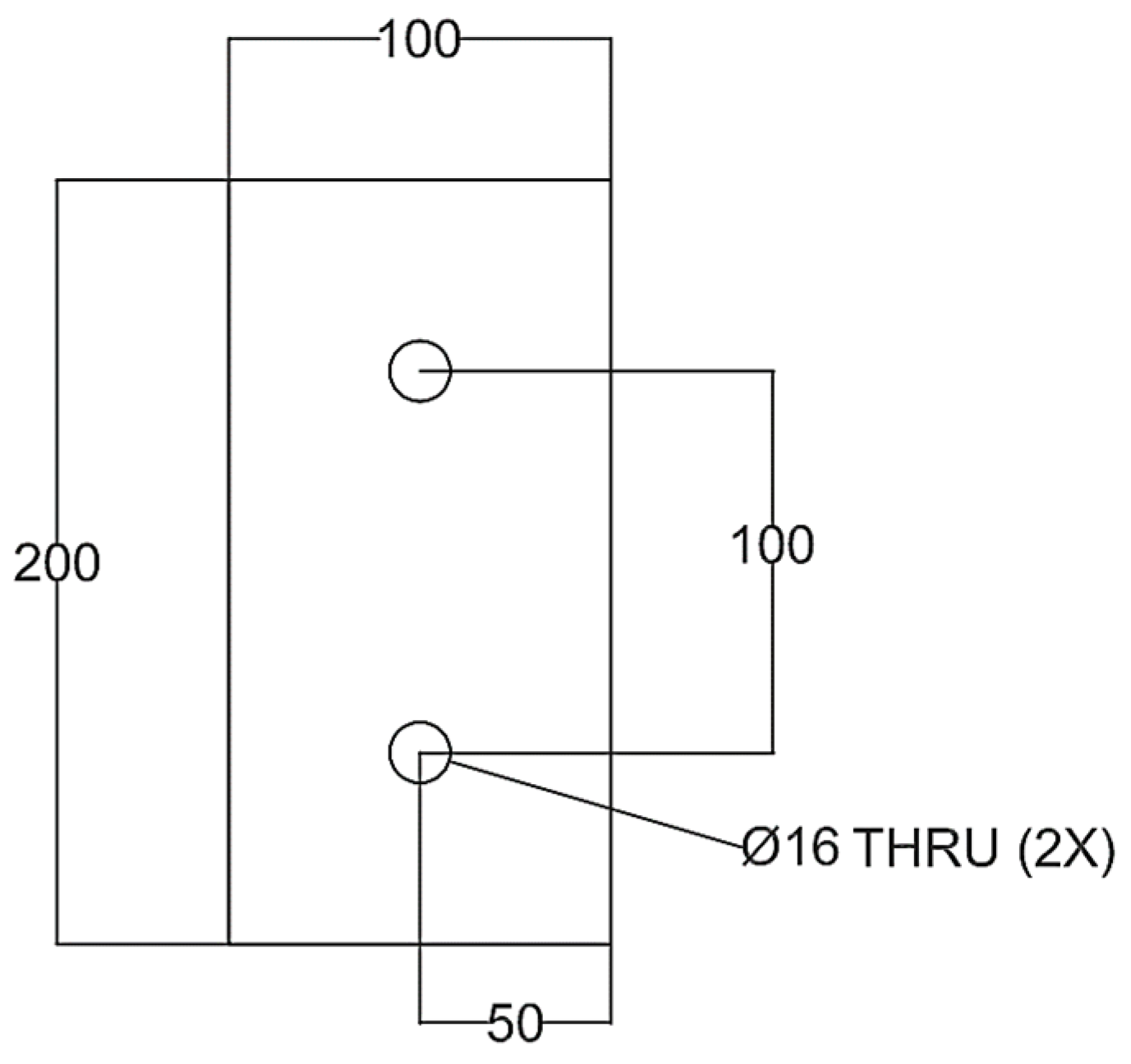
Figure 1. Weld plate (dims in mm).
Jmmp 09 00232 g001
Figure 2. Horizontal 5-axis CNC Z-axis diagram (courtesy of GROB Systems Inc.).
Jmmp 09 00232 g002
Figure 3. Adaptive torque control process.
Jmmp 09 00232 g003
Figure 4. Welding setup with X-Y-X coordinate plane.
Jmmp 09 00232 g004
Figure 5. Tensile sample (dims in mm).
Jmmp 09 00232 g005
Figure 6. Weld samples prepared for tensile testing. White dotted line represents center of weld seam.
Jmmp 09 00232 g006
Figure 7. Weld samples after tensile testing. White dotted line represents center of weld seam.
Jmmp 09 00232 g007
Figure 8. Tensile test results labeled by weld sample #.
Jmmp 09 00232 g008
Figure 9. Average UTS and Std. Dev. grouped by weld parameter.
Jmmp 09 00232 g009
Figure 10. Crack in top of sample #15 (9.4 kN/200 mm/min) before tensile test.
Jmmp 09 00232 g010
Figure 11. Microscopic images before (top) and after (bottom) destruction of 9.4 kN samples. Voids circled in red with weld outlined in yellow. (14) 100 mm/min, (15 and 16) 200 min/min, (17 and 18) 300 mm/min.
Jmmp 09 00232 g011
Figure 12. Lazy “S” in sample 18 (9.4 kN/300 mm/min) before (left) and after (right) destruction.
Jmmp 09 00232 g012
Figure 13. Microscopic comparison of 8.3 kN samples (7, 9, 11) and 9.4 kN samples (14, 16, 18) at 100 (top), 200 (middle), and 300 (bottom) mm/min.
Jmmp 09 00232 g013
Figure 14. Main Effects Plot for Means.
Jmmp 09 00232 g014
Table 1. Chemical and mechanical properties of Al-6061-T6 [7,8].
Chemical Composition
MgSiCrCuMnTiFeZnOther
1.000.600.200.280.150.150.700.250.20
Physical and Mechanical Properties
DensityElastic ModulusThermal ConductivityTensile StrengthHardnessYield
(kg/m3)(GPa)(W/m·K)(MPa)(Brinell)(MPa)
27006916731095275
Table 2. Parameter table.
LevelAxial Force
(kN)
Feed Rate
(mm/min)
17.3100
28.3200
39.4300
Table 3. Weld conditions by sample #.
Sample #Axial Force
(kN)
Feed Rate
(mm/min)
17.3100
27.3100
37.3200
47.3200
57.3300
67.3300
78.3100
88.3100
98.3200
108.3200
118.3300
128.3300
139.4100
149.4100
159.4200
169.4200
179.4300
189.4300
Table 4. Response table for S/N ratios and means.
Response Table for S/N RatiosResponse Table for Means
LevelAxial ForceFeed RateAxial ForceFeed Rate
145.1145.82181.8196.2
245.9644.9199.2177.2
344.4144.76168175.7
Delta1.551.0631.220.5
Rank1212
Table 5. Analysis of variance results for UTS.
SourceDFAdj SSAdj MSF-Valuep-Value
Axial Force229261463.24.170.040
Feed Rate21567783.52.230.147
Error134561350.8
Lack-of-Fit43088771.94.720.025
Pure Error91473163.7
Total179054
Disclaimer/Publisher’s Note: The statements, opinions and data contained in all publications are solely those of the individual author(s) and contributor(s) and not of MDPI and/or the editor(s). MDPI and/or the editor(s) disclaim responsibility for any injury to people or property resulting from any ideas, methods, instructions or products referred to in the content.