
Engineering Perfection in GTAW Welding: Taguchi-Optimized Root Height Reduction for SS316L Pipe Joints


Abstract
1. Introduction
2. Materials and Methods
2.1. Experimental Setup
2.2. Process Parameters and Experimental Design
- Amperage (A): 85, 90, 100
- Voltage (V): 10, 11, 12
- Welding Speed: 50 mm/min, 60 mm/min, 70 mm/min
- Root Gap: 1.0 mm, 1.5 mm, 2.0 mm
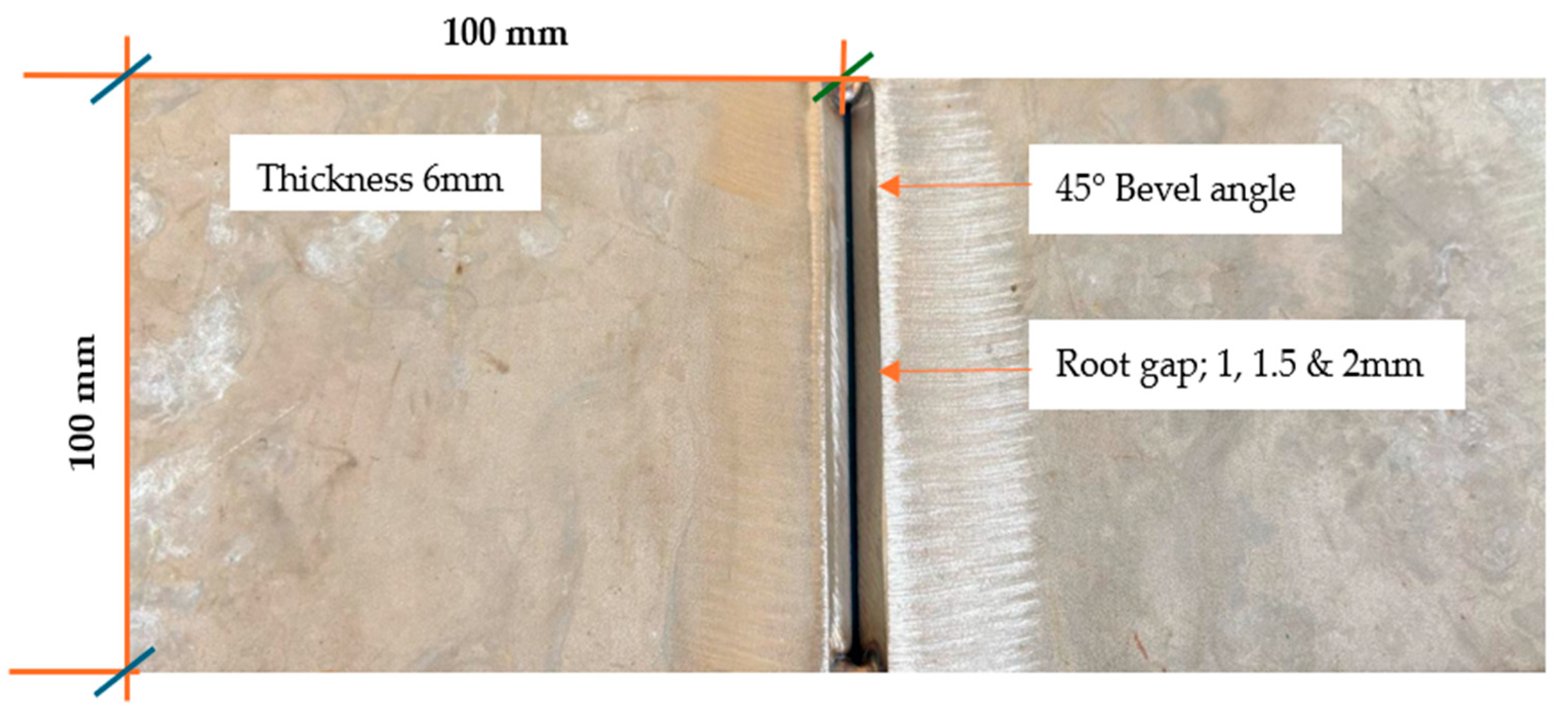
2.3. Plate Materials and Method for Experimental Analysis
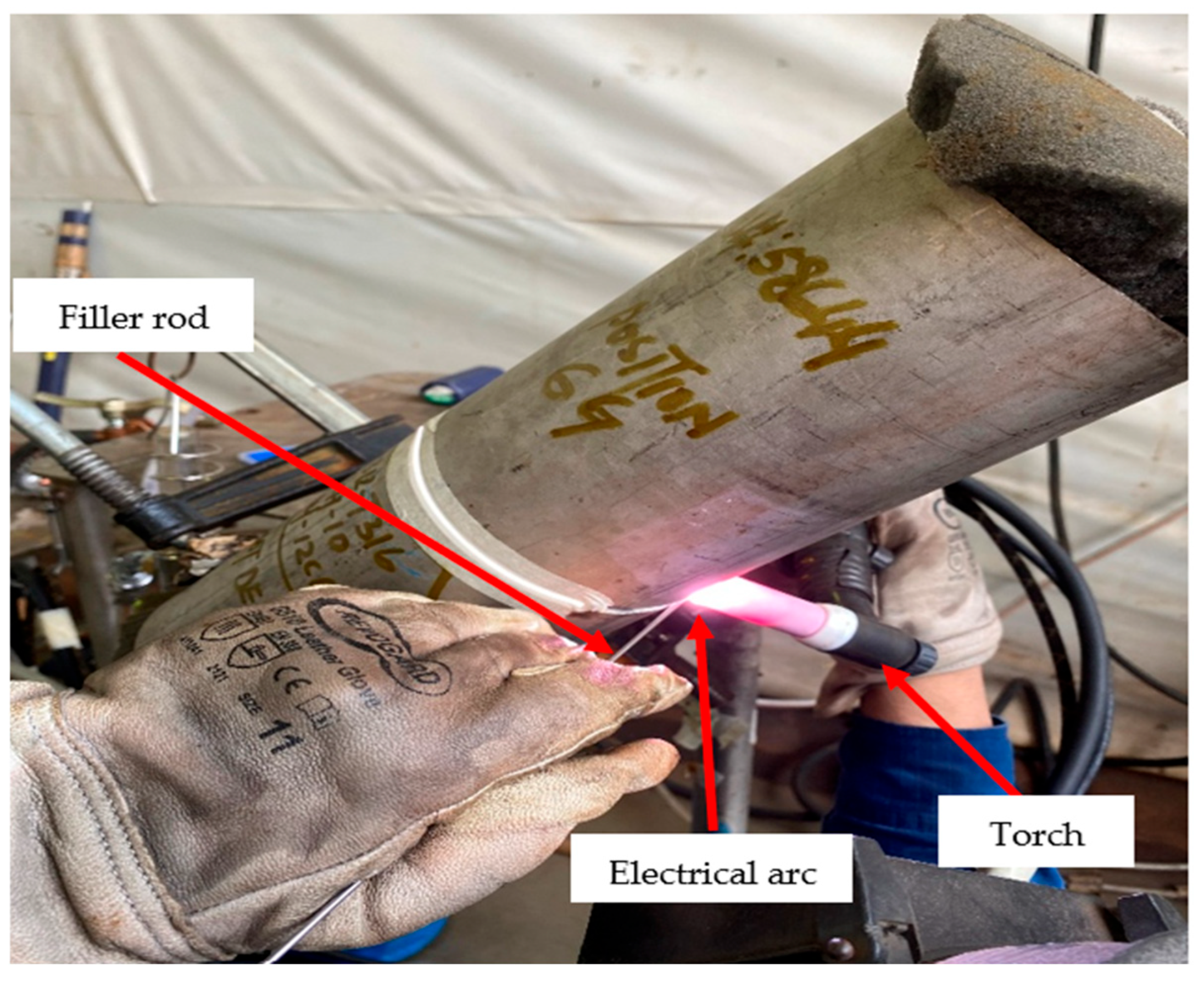
2.4. Pipe Materials and Method for Experimental Analysis
- Before welding:
- During welding:
- After welding:
2.5. Measurement Techniques
2.6. Statistical Analysis Methods
3. Results and Discussion
3.1. Weld Quality Assessment Based on Parameter Variation
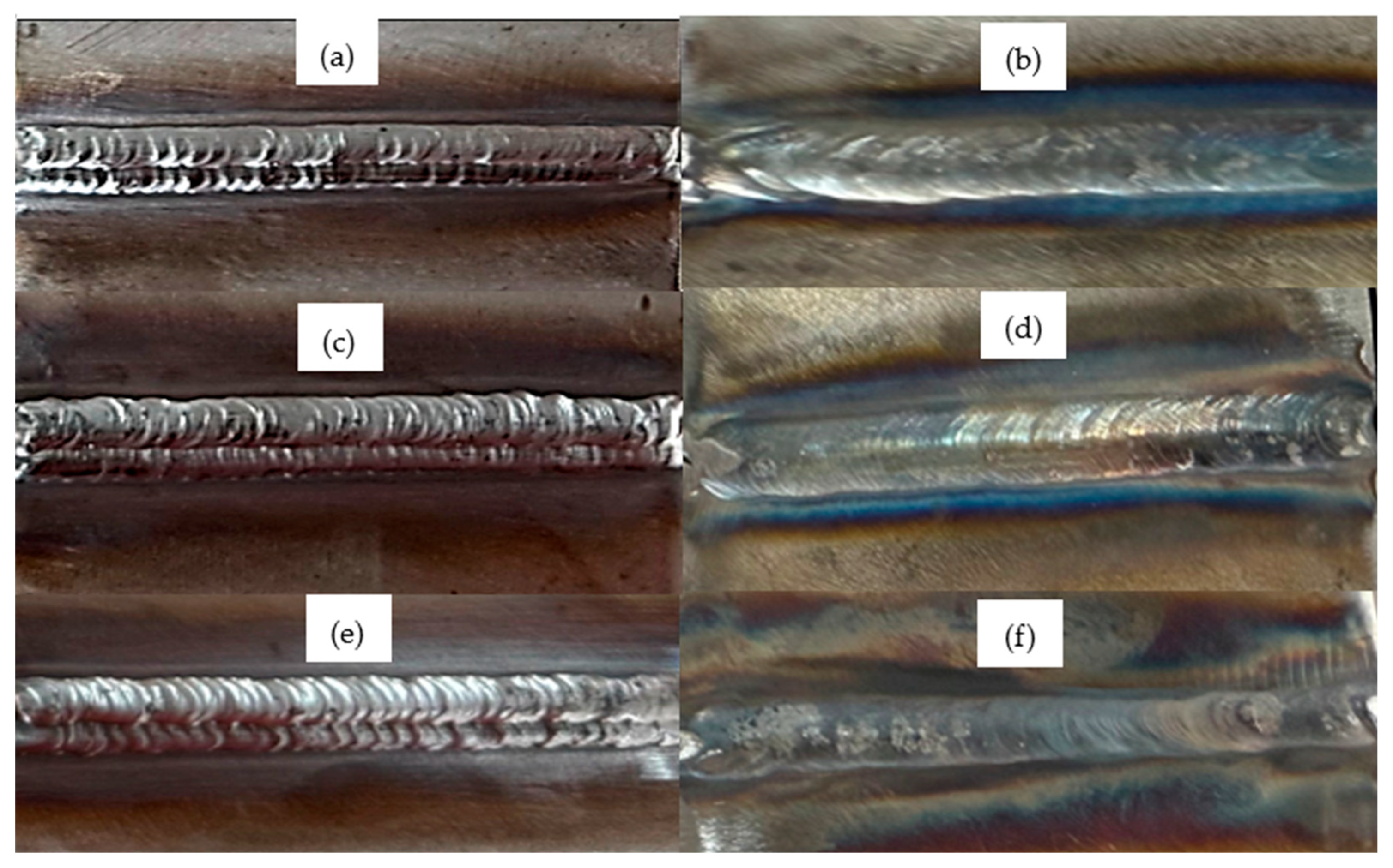
3.2. Visual and Dimensional Assessment of Weld Root Quality
3.3. Internal Weld Root Quality Assessment of Pipe Joints
3.4. Penetrant Testing for Surface Defect Evaluation in Welded Pipe Joints
3.5. Radiographic Profile Analysis and Macro Examination of Welded Pipe Joints
3.6. Regression Model (Enhanced with R2 and Model Validation)
3.7. ANOVA
3.8. Main Effects Plot
- Amperage:
- Voltage:
- Welding Speed:
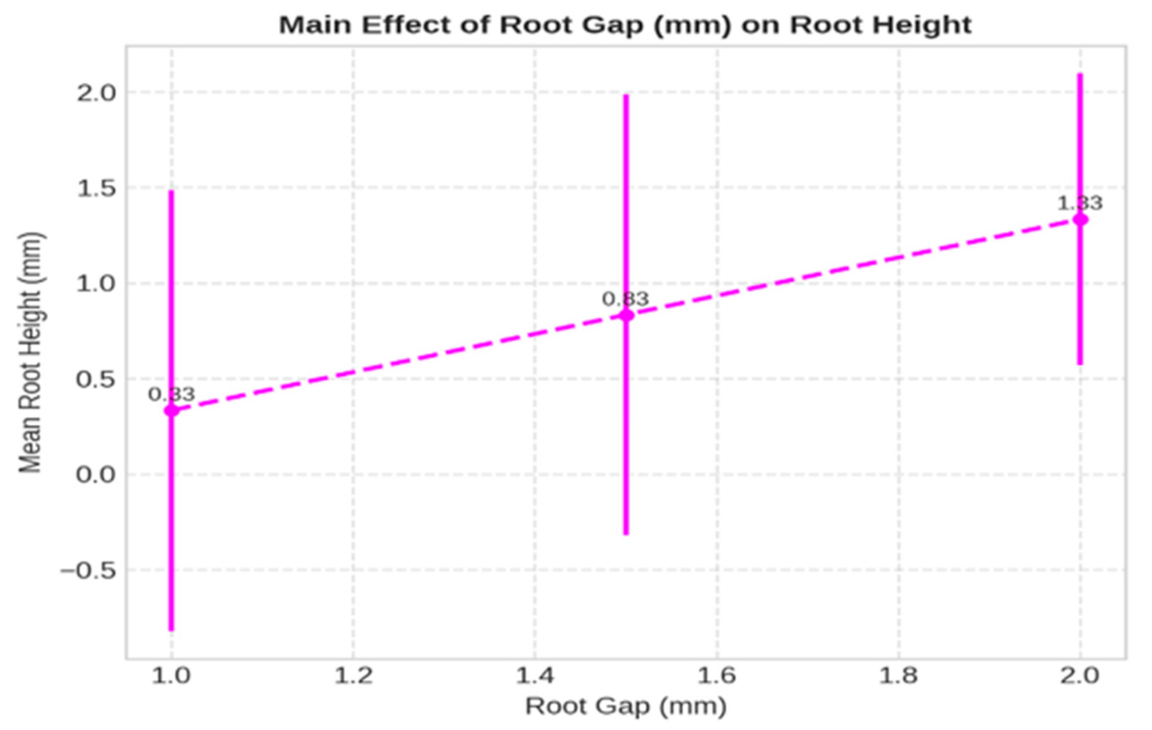
- Root Gap:
- Synthesis of Findings;
- Amperage: Exhibits a strong, direct correlation with root height and remains the primary determinant of fusion depth.
- Root Gap: Provides geometric control over weld root accessibility, significantly affecting arc concentration and penetration.
- Voltage: Plays a stabilizing role with moderate thermal influence.
- Speed: Modulates heat input per unit length in a nonlinear fashion, with optimal ranges balancing melting and solidification rates.
3.9. Signal-to-Noise Ratio Analysis
- Amperage: The S/N ratio significantly improves as amperage increases from 85 A to 90 A, reaching its peak at 90 A, and then declines at 100 A. This indicates that 90 A delivers the most consistent and reliable root height results. The drop in S/N ratio at 100 A may be attributed to excessive heat input, leading to root over-penetration and oxidation variability, as confirmed by supporting metallurgical observations.
- Voltage: The voltage plot reveals that the S/N ratio is highest at 11 V, suggesting optimal arc characteristics and energy transfer at this level. Both lower (10 V) and higher (12 V) voltage levels resulted in reduced S/N ratios, indicating less stability in weld bead formation. This supports the idea that mid-level voltage balances arc stiffness and arc length for consistent heat distribution.
- Travel Speed: The S/N ratio increases progressively with welding speed, reaching its maximum at 70 mm/min. At lower speeds (50–60 mm/min), the arc spends more time on the base metal, increasing thermal input and leading to higher variability in penetration. The improved consistency at 70 mm/min is likely due to more efficient energy transfer and reduced distortion effects, resulting in a tighter control of root height.
- Root Gap: Among all parameters, root gap shows a clearly defined optimal point at 1.5 mm, where the S/N ratio is maximized. This suggests that a moderate root opening facilitates proper filler distribution and arc access while minimizing the risk of fusion defects or excessive penetration. Too narrow (1.0 mm) or too wide (2.0 mm) gaps reduce process stability and repeatability.
3.10. Genetic Algorithm Optimization with Convergence and Validation Insights
3.10.1. Rationale and Methodology
- Optimizing welding parameters is essential to ensuring sound joint formation, dimensional accuracy, and overall weld integrity, particularly in critical applications. In the present study, a genetic algorithm (GA) was employed to optimize the GTAW parameters for mild steel. The optimization objective focused on minimizing root height, constrained to an upper bound of 2 mm, while concurrently satisfying visual acceptability and the absence of oxidation defects.
- Y: root height (mm),
- I: amperage (A),
- V: arc voltage (V),
- S: travel speed (mm/min),
- G: root gap (mm).
- Population size: 10 individuals
- Generations: 200
- Gene space: Amperage (85–100 A), voltage (10–12 V), speed (50–70 mm/min), root gap (1.0–2.0 mm)
- Selection strategy: Steady-state selection
- Crossover type: Single-point crossover
- Mutation: Random mutation applied to 25% of genes per generation
3.10.2. Genetic Algorithm Optimization Result
3.10.3. Benchmarking Against Grid Search
3.11. Outcome
4. Implications for Code Compliance and Critical Piping Integrity
5. Validation of Weld Quality Against ASME B31.3 and Practical Implications for Industry
6. Conclusions
Author Contributions
Funding
Data Availability Statement
Acknowledgments
Conflicts of Interest
References
- Sharma, P.; Chattopadhyaya, S.; Singh, N.K.; Kumar, A.; Sharma, S.; Li, C.; Kumar, V.; Wojciechowski, S.; Krolczyk, G.; Eldin, S.M. Recent developments in the design, development, and analysis of the influence of external magnetic-field on gas-metal arc welding of non-ferrous alloys: Review on optimization of arc-structure to enhance the morphology, and mechanical properties of welded joints for automotive applications. Heliyon 2022, 8, e11812. [Google Scholar] [PubMed]
- Shao, L.; Zhang, X.; Chen, Y.; Zhu, L.; Wu, S.; Liu, Q.; Li, W.; Xue, N.; Tu, Z.; Wang, T. Why do cracks occur in the weld joint of Ti-22Al-25Nb alloy during post-weld heat treatment? Front. Mater. 2023, 10, 1135407. [Google Scholar] [CrossRef]
- Xu, X.; Hao, Y.; Dong, R.; Hou, H.; Zhao, Y. Effect of undercooling on microstructure evolution of Cu based alloys. J. Alloys Compd. 2023, 935, 167998. [Google Scholar] [CrossRef]
- Saxena, A.; Saxena, K.K.; Singh, B.; Rajput, S.K.; Yelamasetti, B. Study and effect of GTAW parameters on mechanical properties of aluminium dissimilar welded joints: Optimization technique. Int. J. Interact. Des. Manuf. 2024, 18, 1231–1241. [Google Scholar] [CrossRef]
- Liu, J.; Xu, J.; Paik, K.W.; He, P.; Zhang, S. In-situ isothermal aging TEM analysis of a micro Cu/ENIG/Sn solder joint for flexible interconnects. J. Mater. Sci. Technol. 2024, 169, 42–52. [Google Scholar] [CrossRef]
- Wang, C.; Wang, Z.; Zhang, S.; Liu, X.; Tan, J. Reinforced quantum-behaved particle swarm-optimized neural network for cross-sectional distortion prediction of novel variable-diameter-die-formed metal bent tubes. J. Comput. Des. Eng. 2023, 10, 1060–1079. [Google Scholar] [CrossRef]
- Wang, Z.; Zhou, T.; Zhang, S.; Sun, C.; Li, J.; Tan, J. Bo-LSTM based cross-sectional profile sequence progressive prediction method for metal tube rotate draw bending. Adv. Eng. Informatics. 2023, 58, 102152. [Google Scholar] [CrossRef]
- Kutelu, B.J.; Seidu, S.O.; Eghabor, G.I.; Ibitoye, A.I. Review of GTAW Welding Parameters. J. Miner. Mater. Charact. Eng. 2018, 6, 541–554. [Google Scholar] [CrossRef]
- Chohan, J.S.; Mittal, N.; Kumar, R.; Singh, S.; Sharma, S.; Singh, J.; Rao, K.V.; Mia, M.; Pimenov, D.Y.; Dwivedi, S.P. Mechanical strength enhancement of 3d printed acrylonitrile butadiene styrene polymer components using neural network optimization algorithm. Polymers 2020, 12, 2250. [Google Scholar] [CrossRef]
- Chohan, J.S.; Kumar, R.; Singh, T.C.B.; Singh, S.; Sharma, S.; Singh, J.; Mia, M.; Pimenov, D.Y.; Chattopadhyaya, S.; Dwivedi, S.P.; et al. Taguchi s/n and topsis based optimization of fused deposition modelling and vapor finishing process for manufacturing of ABS plastic parts. Materials 2020, 13, 5176. [Google Scholar] [CrossRef]
- Reddy, K.S.; Vemanaboina, H.; Naidu, B.V.V.; Yelamasetti, B.; Bridjesh, P.; Shelare, S.D. Minimizing distortion in multi-pass GTAW welding of SS316L structures: A Taguchi approach. Int. J. Interact. Des. Manuf. 2024, 18, 3691–3698. [Google Scholar] [CrossRef]
- Khan, A.M.; Jamil, M.; Mia, M.; Pimenov, D.Y.; Gasiyarov, V.R.; Gupta, M.K.; He, N. Multi-objective optimization for grinding of AISI D2 steel with Al2O3 wheel under MQL. Materials 2018, 11, 2269. [Google Scholar] [CrossRef] [PubMed]
- Singh, L.; Singh, A.; Singh, B. Study and Optimize the Mag Parametric Influence on Impact Strength of Aa6061 Joint By Taguchi and Anova. In AIP Conference Proceedings; AIP Publishing: Melville, NY, USA, 2023. [Google Scholar]
- Choudhary, M.A. The structural integrity of high-strength welded pipeline steels: A review. Int. J. Struct. Integr. 2020, 11, 711–737. [Google Scholar]
- Zhang, Y.; Liu, H. Real-time monitoring and control of gas tungsten arc welding process using machine learning techniques. J. Manuf. Process. 2023, 78, 345–355. [Google Scholar] [CrossRef]
- Kumar, R.; Gupta, S. Machine learning applications in welding: A review. Weld. J. 2022, 101, 123–132. [Google Scholar]
- Lee, S.H.; Kim, J. Industry 4.0 and its impact on welding technology: A review. Int. J. Adv. Manuf. Technol. 2021, 113, 3047–3061. [Google Scholar]
- Patil, R.; Rao, P.S. Influence of heat input on microstructure and mechanical properties of GTAW joints in stainless steel. Mater. Sci. Eng. A 2023, 853, 143–154. [Google Scholar] [CrossRef]
- Singh, A.; Sharma, S. Energy-efficient welding processes: A sustainable approach. J. Clean. Prod. 2022, 331, 129–139. [Google Scholar] [CrossRef]
- ASME-BPVC.IX-2021; ASME BPVC.IX-2021/ASME Boiler and Pressure Vessel Code. Section IX: Qualification Standard for Welding, Brazing, and Fusing Procedures; Welders, Brazers, and Welding, Brazing, and Fusion Operators. ASME: New York, NY, USA, 2021.
- Taskin, M.; Caligulu, U.; Turkmen, M. X-Ray tests of AISI430 and 304 stainless steels and AISI 1010 low carbon steel welded by CO2 laser beam welding. Mater. Test. 2011, 53, 741–747. [Google Scholar] [CrossRef]
- Desai, V.; Pal, M.; Banjare, M.; Nancharaiah, C.; Guria, S.; Vardhan, H. Use of Profile Radiography Technique for In-Service Inspection in Petroleum Refinery—Case Studies. National Seminar & Exhibition on Non-Destructive Evaluation, NDE 2011, 8–10 December 2011. 2012. Available online: https://www.ndt.net/?id=11972 (accessed on 24 May 2025).
- Ivanov, A.; Petrov, M.; Sidorov, V. Reliability of Dye Penetrant Inspection Method to Detect Weld Discontinuities. J. Non-Destruct. Test. 2023, 30, 215–228. [Google Scholar] [CrossRef]
- Juang, S.C.; Tarng, Y.S. Process parameter selection for optimizing the weld pool geometry in the tungsten inert gas welding of stainless steel. J. Mater. Process. Technol. 2008, 202, 403–412. [Google Scholar] [CrossRef]
- Kiran, M. Optimization of Welding Parameters in GTAW Process Using Taguchi Method. Mater. Today Proc. 2018, 5, 2209–2216. [Google Scholar]
- ASME B31.3-2016; Process Piping. American Society of Mechanical Engineers: New York City, NY, USA, 2016.
- Mackey, M.; Reddy, S. Effects of excess weld root on flow characteristics. J. Fluid Eng. 2005, 127, 459–466. [Google Scholar]
- Lin, M.C.; Cheng, C.C.; Huang, C.C. Study on the Application of the GTAW Process in Strengthening the Welding Quality of Short Duplex Stainless Pipe. Metals 2022, 12, 1691. [Google Scholar] [CrossRef]


| Description | C | Si | Mn | P | S | Cr | Mo | Ni | Cu | N |
|---|---|---|---|---|---|---|---|---|---|---|
| Avesta GT 316L filler wire (Manufactured by Outokumpu Stainless AB, Avesta, Sweden) | 0.02 | 0.45 | 1.55 | 0.025 | 0.008 | 18.15 | 2.57 | 11.33 | 0.08 | 0.07 |
| Base Material 316L (YC Inox Co. Ltd. Changhua, Taiwan (R.O.C.) and certified under EN 10204-3.1:2004.) | 0.02 | 0.45 | 1.43 | 0.028 | 0.01 | 16.85 | 2.03 | 10.02 | NA | 0.036 |
| Samples | Amp | Vol | Speed | RG | VI | ARPH | Oxi |
|---|---|---|---|---|---|---|---|
| 1 | 85 | 10 | 50 | 1 | 0 | −1.0 mm | 0 |
| 2 | 85 | 11 | 60 | 1.5 | 0 | −0.5 mm | 0 |
| 3 | 85 | 12 | 70 | 2 | 1 | 0.5 mm | 0 |
| 4 | 90 | 10 | 60 | 1 | 1 | 1.0 mm | 1 |
| 5 | 90 | 11 | 70 | 1.5 | 1 | 1.5 mm | 1 |
| 6 | 90 | 12 | 50 | 2 | 1 | 2.0 mm | 1 |
| 7 | 100 | 10 | 70 | 1 | 1 | 1.0 mm | 0 |
| 8 | 100 | 11 | 50 | 1.5 | 1 | 1.5 mm | 0 |
| 9 | 100 | 12 | 60 | 2 | 1 | 1.5 mm | 0 |
| Sample | Amperage | Voltage | Speed | Root Gap | (0.0929 × Amperage) | (0.4000 × Voltage) | (0.0083 × Speed) | (0.2000 × Root Gap) | Predicted Root Height |
|---|---|---|---|---|---|---|---|---|---|
| 1 | 85 | 10 | 50 | 1 | 7.8965 | 4 | 0.415 | 0.2 | −0.3671 |
| 2 | 85 | 11 | 60 | 1.5 | 7.8965 | 4.4 | 0.498 | 0.3 | 0.2159 |
| 3 | 85 | 12 | 70 | 2 | 7.8965 | 4.8 | 0.581 | 0.4 | 0.7989 |
| 4 | 90 | 10 | 60 | 1 | 8.361 | 4 | 0.498 | 0.2 | 0.1804 |
| 5 | 90 | 11 | 70 | 1.5 | 8.361 | 4.4 | 0.581 | 0.3 | 0.7634 |
| 6 | 90 | 12 | 50 | 2 | 8.361 | 4.8 | 0.415 | 0.4 | 1.0974 |
| 7 | 100 | 10 | 70 | 1 | 9.29 | 4 | 0.581 | 0.2 | 1.1924 |
| 8 | 100 | 11 | 50 | 1.5 | 9.29 | 4.4 | 0.415 | 0.3 | 1.5264 |
| 9 | 100 | 12 | 60 | 2 | 9.29 | 4.8 | 0.498 | 0.4 | 2.1094 |
| Source | Sum of Squares | df | F-Value | p-Value | % Contribution |
|---|---|---|---|---|---|
| Amperage | 6.167 | 2 | 37.000 | 0.026 | 64.913% |
| Voltage | 1.500 | 2 | 9.000 | 0.100 | 15.789% |
| Speed | 0.167 | 2 | 1.000 | 0.500 | 1.754% |
| Root Gap | 1.500 | 2 | 9.000 | 0.100 | 15.789% |
| Residual | 0.167 | 2 | N/A | N/A | 1.754% |
| Parameter | Optimal Value |
|---|---|
| Amperage | 90.0 A |
| Voltage | 11.0 V |
| Speed | 70.0 mm/min |
| Root Gap | 1.5 mm |
| Predicted Root Height | 0.751 mm |
| Amperage | Voltage | Speed | Root Gap | Root Height | Visual | Oxidation |
|---|---|---|---|---|---|---|
| 90 | 10 | 60 | 1 | 0.171 mm | ✓ | ✓ |
| 90 | 11 | 70 | 1.5 | 0.751 mm | ✓ | ✓ |
| 90 | 12 | 50 | 2 | 1.091 mm | ✓ | ✓ |
Disclaimer/Publisher’s Note: The statements, opinions and data contained in all publications are solely those of the individual author(s) and contributor(s) and not of MDPI and/or the editor(s). MDPI and/or the editor(s) disclaim responsibility for any injury to people or property resulting from any ideas, methods, instructions or products referred to in the content. |
© 2025 by the authors. Licensee MDPI, Basel, Switzerland. This article is an open access article distributed under the terms and conditions of the Creative Commons Attribution (CC BY) license (https://creativecommons.org/licenses/by/4.0/).
Share and Cite
Sohel, M.; Sharma, V.S.; Arumugam, A. Engineering Perfection in GTAW Welding: Taguchi-Optimized Root Height Reduction for SS316L Pipe Joints. J. Manuf. Mater. Process. 2025, 9, 188. https://doi.org/10.3390/jmmp9060188
Sohel M, Sharma VS, Arumugam A. Engineering Perfection in GTAW Welding: Taguchi-Optimized Root Height Reduction for SS316L Pipe Joints. Journal of Manufacturing and Materials Processing. 2025; 9(6):188. https://doi.org/10.3390/jmmp9060188
Chicago/Turabian StyleSohel, Mohammad, Vishal S. Sharma, and Aravinthan Arumugam. 2025. "Engineering Perfection in GTAW Welding: Taguchi-Optimized Root Height Reduction for SS316L Pipe Joints" Journal of Manufacturing and Materials Processing 9, no. 6: 188. https://doi.org/10.3390/jmmp9060188
APA StyleSohel, M., Sharma, V. S., & Arumugam, A. (2025). Engineering Perfection in GTAW Welding: Taguchi-Optimized Root Height Reduction for SS316L Pipe Joints. Journal of Manufacturing and Materials Processing, 9(6), 188. https://doi.org/10.3390/jmmp9060188