Article

Tube Joining by a Sheet Flange Connection

IDMEC, Instituto Superior Técnico, Universidade de Lisboa, Av. Rovisco Pais, 1049-001 Lisboa, Portugal
*
Author to whom correspondence should be addressed.
J. Manuf. Mater. Process. 2023, 7(1), 12; https://doi.org/10.3390/jmmp7010012
Submission received: 5 December 2022 / Revised: 19 December 2022 / Accepted: 24 December 2022 / Published: 29 December 2022
(This article belongs to the Special Issue Joining of Unweldable Materials: Concepts, Techniques and Processes)

Abstract

:
Joining of tubes to tubes by means of plastic deformation at ambient temperature allows one to solve the main limitations produced by the necessity of joining thin-walled tubes of low-to-medium diameter size made from materials that are not suitable to be welded and/or have reduced contact interfaces. The new joining solution allows one to obtain permanent mechanical joints of tubes or pipes by means of an accessory lightweight sheet metal flange subjected to annular indentation and subsequent injection of its material towards the tube walls to produce a mechanical interlock between the different elements. The sheet-flange connection can then be utilized to affix the joined tube assembly to walls or other different structures and equipment, by means of fasteners or other joining accessories attached to the sheet flange. Similar or dissimilar material combinations can be easily and safely produced while guaranteeing levels of leak-tightness within the maximum internal operating pressure of the individual tubes. A combined numerical–experimental approach is employed to identify the operative parameters as well as to explain the deformation conditions. Pull-out loads and internal fluid pressure are applied to the manufactured joint to evaluate its behavior under typical operating conditions that it may be subjected to during its service life depending on the application.

1. Introduction

The joining of tubes to tubes was, until recently, limited to welding techniques, but the need to produce lightweight assemblies made from dissimilar materials that are able to offer new capabilities, makes the utilization of welding unfeasible and has triggered the development of joining by plastic deformation [1,2,3,4,5,6,7]. These joining-by-forming techniques eliminate the need for heat input and manufacturing complexity, thus contributing to cost and energy savings.
In regards to tube-to-tube joining, different solutions have been developed to produce those joints. Tube joining was previously performed in thin-walled tubes that, when subjected to axial compression, trigger the development of out-of-plane instability waves with different inclination angles that secure the tubes together [8]. The utilization of axisymmetric plastic instability is able to produce mechanical joints at the tubes’ ends with external mechanical interlocking by a two-stage tube-forming process [9], in which one of the tubes is initially expanded to allow the introduction of the other tube, followed by the forming of a compression bead between the two materials as a result of localized plastic instability which locks them together. Alternatively, the production of internal interlockings in tube-to-tube joints can be obtained by a combination of tube end reduction and rounding over the opposite tube, with subsequent clamping of the two tubes. An alternative that can also produce internal joints between tubes but of different diameters is rotary swagging [10]. The incremental forming process utilizes three, four or even eight dies arranged concentrically around the tubes that move simultaneously in both the radial and axial directions, thus reducing the diameters of the tubes and producing a mechanical interlocking between them.
Metal sheets were recently joined to PVC tubes to produce polymer–metal sheet-tube connections [11,12]. A deformation-assisted joining process that consists of the annular indentation of the sheet surface adjacent to the tube in order to produce an injection of sheet material towards the tube and shape a form-fitted joint between them has been extensively developed. The mechanical joints can be produced either at the tube ends [12] or away from the tube ends [13,14,15,16].
The new joining solution presented here retrieves the concepts of indentation and injection to produce a mechanical connection between the tubes that is motivated by the adjacent sheet flange. The two stages of the process are presented in Figure 1 where the chamfered upper tube end is compressed against the chamfered end of the lower tube, which reduces the upper tube radially and creates adjacent counter-facing surfaces between the two tubes to be joined (Figure 1a). From here, the sheet flange is positioned in the middle of the contact interface between the tubes and its surface is indented by the upper punch which motivates the sheet material at the adjacent region of the sheet hole to be displaced against the tubes and to produce a mechanical interlocking (Figure 1b).
For demonstrating the potential of the joining solution, mechanical connections between polyvinylchloride (PVC) tubes, which are extensively utilized for water and sewage supply lines and low-pressure equipment, along with connections between PVC and aluminum tubes which are utilized in several structural applications will be analyzed both numerically and experimentally. This analysis will allow us to determine the major operating parameters and their influence in the overall deformation process. Finally, the performance of the joints is evaluated by the application of pull-out loads and internal pressure to draw conclusions about the critical force values that the mechanical joints can withstand before critical failure.

2. Materials and Methods

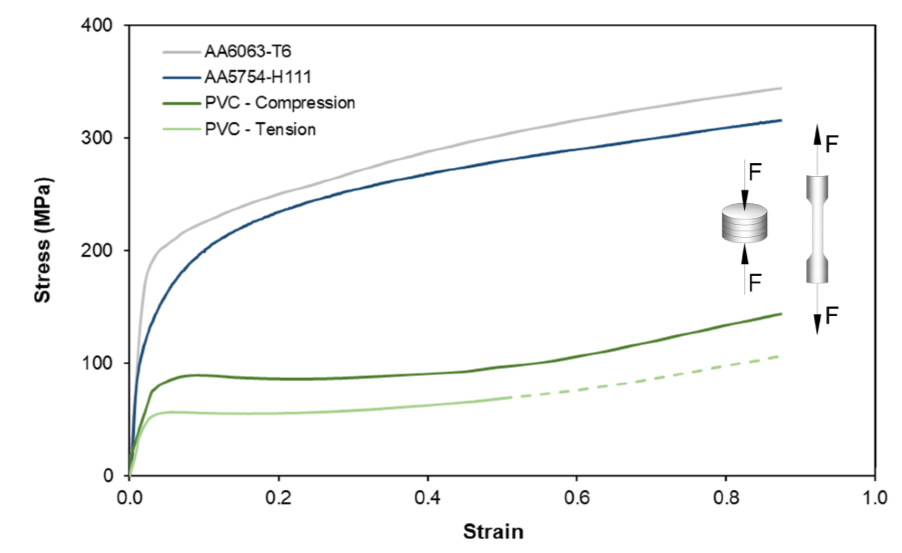
2.1. Material Properties

Three different types of materials were subjected to a mechanical characterization for the present research work. One of those materials was in the form of tubes of commercial PVC-U (Unplasticized Polyvinylchloride) with an outer radius of 16 mm and a thickness of 1.5 mm. This tube is suitable for high service pressure up to a maximum value of 16 bar (at 20 °C), and it is commonly utilized in the installation and equipment of water and sewage supplies. The remaining materials utilized were aluminum AA6063-T6 tubes with a 32 mm external diameter and a 1.5 mm wall thickness along with aluminum AA5754-H111 sheets with 5 mm thickness. These materials are commonly utilized in applications from the automotive, aerospace, construction and naval fields.
To account for the strength-differential effect of PVC, the stress–strain curves were obtained by tensile and stack compression tests: the tensile test specimens were machined from the supplied tubes and sheets in accordance with the ASTM D638 and ASTM E8/E8M standards, while the stack compression test specimens were obtained by axial compression of three circular discs cut from the supplied materials. All tests were carried out on a hydraulic testing machine (Instron SATEC 1200 kN) with a cross-head speed equal to 10 mm/min in ambient temperature conditions. Their resulting evolutions of effective stress and strain are presented in the graph of Figure 2.

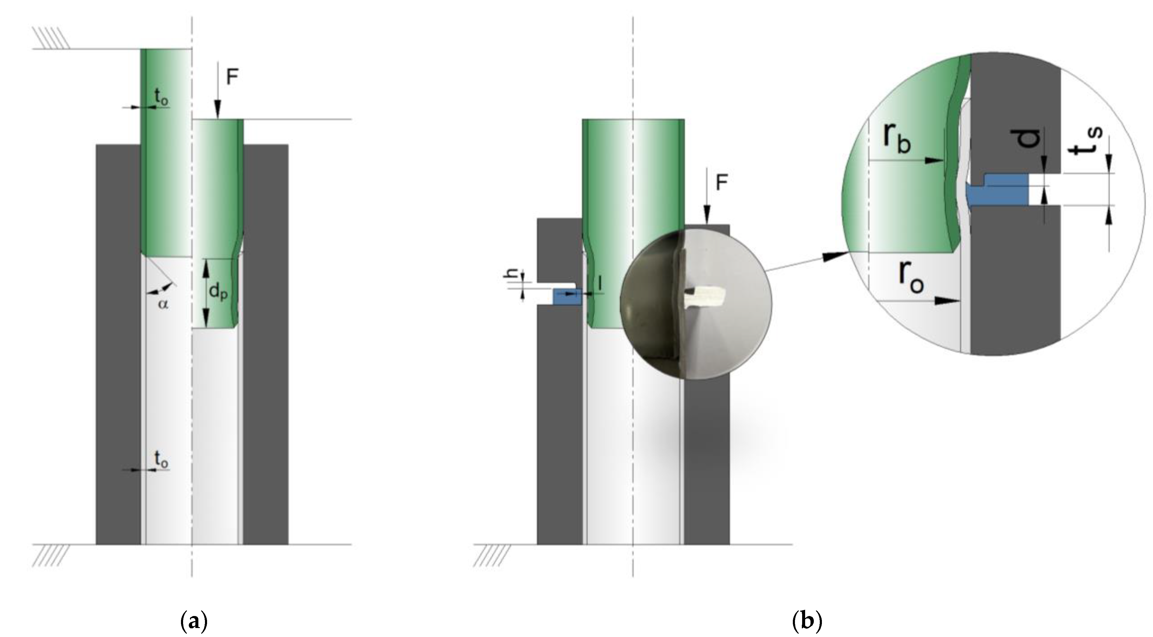
2.2. Numerical and Experimental Test Plan
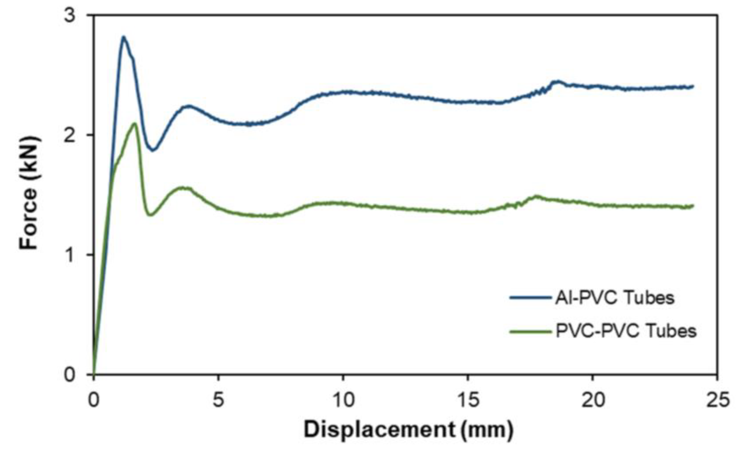
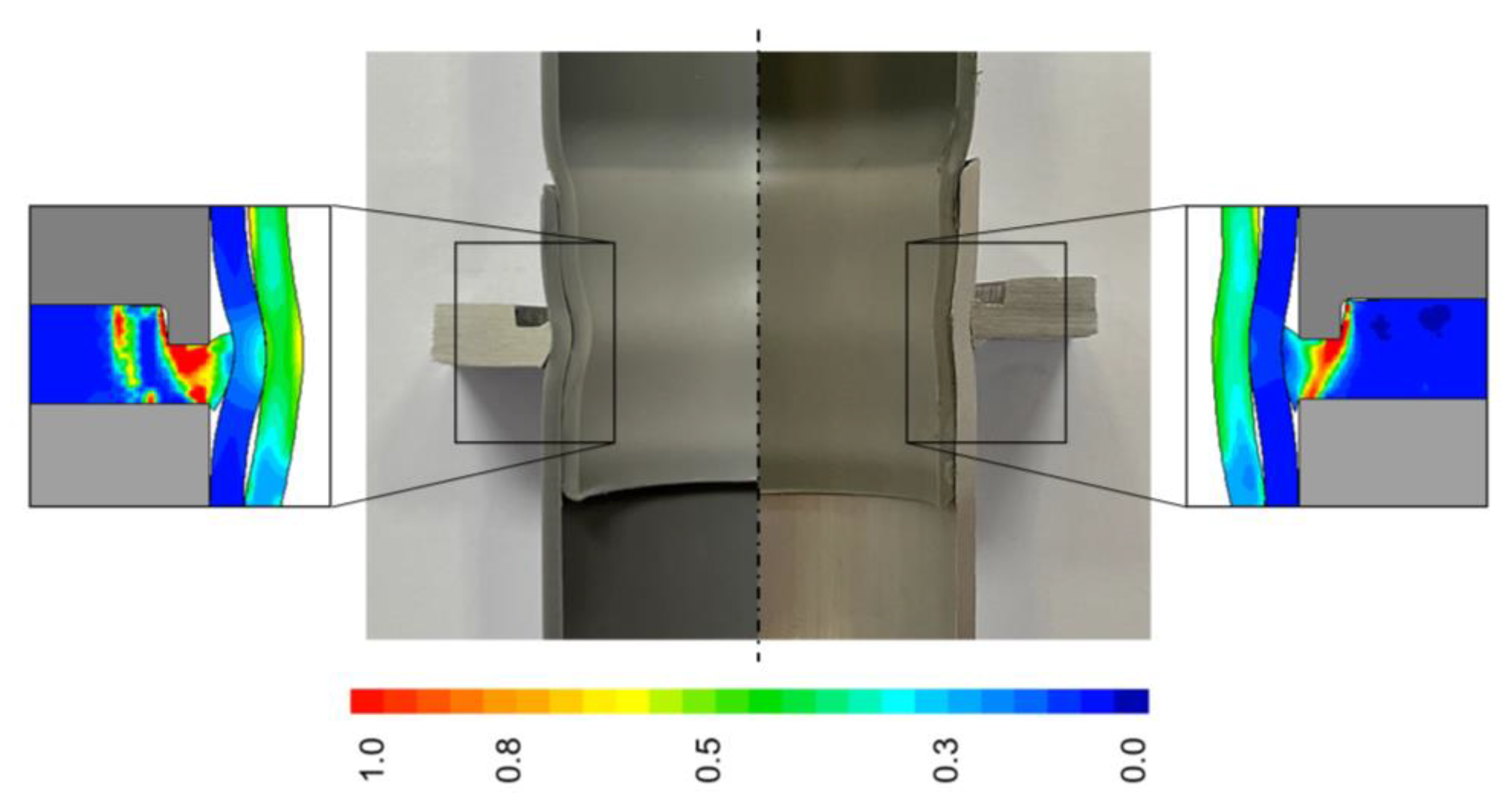
The investigation work was performed by a combination of both numerical and experimental analyses following the setup presented in Figure 1. Different main process parameters were identified for each stage. As for the first stage that produces the tube reduction, the main parameters are the initial internal radius r o and thickness t o of the tubes and the chamfered angle of the tubes’ ends α , as well as the depth of penetration d p which defines the contact region between the inner and outer tubes. For the second stage, the fundamental parameters are those related to indentation and injection of the sheet flange such as the sheet thickness t s , the indentation punch height h , the indentation punch length l and the indentation depth d . The values of all the previous parameters are summarized in Table 1.
The maximum inner tube reduction is quantified by the tube beading radius r b that will allow to form conclusions about the degree of the mechanical interlocking generated by the joining process. The values of the angle α were kept constant for both tubes, since their influence is limited to the clearance between the adjacent counter-facing surfaces of the two tubes to be joined by means of the sheet flange and to the load-displacement evolution required to complete the first stage of the joining process. It has already been observed for a similar operation [8,9] that smaller values of those angles can ensure smaller peak loads and smaller clearances between the tubes.
The values of the indentation and injection operation performed at the second stage of the joining process were retrieved from the original work when it was utilized to join a sheet to a single tube [13,14,15].
All the experimentation work was developed under conditions of ambient temperature and performed with the hydraulic testing machine Instron SATEC 1200 kN, the crosshead speed of which was defined as 10 mm/min. For analyzing the influence of the different parameters listed on Table 1, unit cells consisting of tubes with an initial length of 50 mm and sheet flanges of 50 × 50 mm were fabricated.
For selecting the suitable parameters and understanding the mechanics of the deformation upon the joining process and respective axial detachment, finite element models were created with quadrilateral elements for the cross-sections of both the tubes and sheet flanges (1000 elements and 3000 elements, respectively), modelled with rotational symmetry conditions and assumed to be deformable isotropic objects subjected to axisymmetric loading. The numerical model utilized is presented in Figure 3 for the end of the upper tube reduction stage and at the start of the sheet flange indentation stage (leftmost side), as well as for the completion of the joining process (rightmost side).
For increasing the accuracy of the numerical model performed with the computer program i-form [17], the metallic geometries were modelled accordingly with a von Mises yield plasticity criterion, whereas the polymeric geometries were modelled in accordance with the plasticity criterion of Caddell et al. [18,19]. The latter yield criterion explicitly accounts for the strength-differential effect resulting from the differences between tensile and compressive flow stresses of polymers seen in Figure 2. A law of constant friction τ f = m k , where m is the friction factor and k is the flow shear strength friction, was employed. The value of m was defined as 0.1 for both the contact interfaces between the workpieces and the contact interface of those objects with the tools, and the suitability of this value was validated by the close correlation between the experimental and numerical evolutions. The tool setup was modelled as rigid objects that were discretized by means of linear contact-friction elements.
To evaluate the performance of the mechanical joint under the typical operating conditions that it may be subjected under structural and/or hydraulic working conditions, two different setups were prepared. To simulate the response of the mechanical connection to pull-out loads created either by an external element or by water hammer caused by a fast valve closure in which the fluid flow is rapidly decelerated, causing a higher-pressure surge, the setup of Figure 4a is utilized. To evaluate the leak-tightness of the mechanical joint, the experimental setup of Figure 4b was utilized, which consists of two rubber disks that are inserted at the inner diameter of each tube which is then filled with a fluid, those disks then being compressed until the fluid exits the connection at the contact region where the joint was produced or by the rubber disks themselves.

3. Results

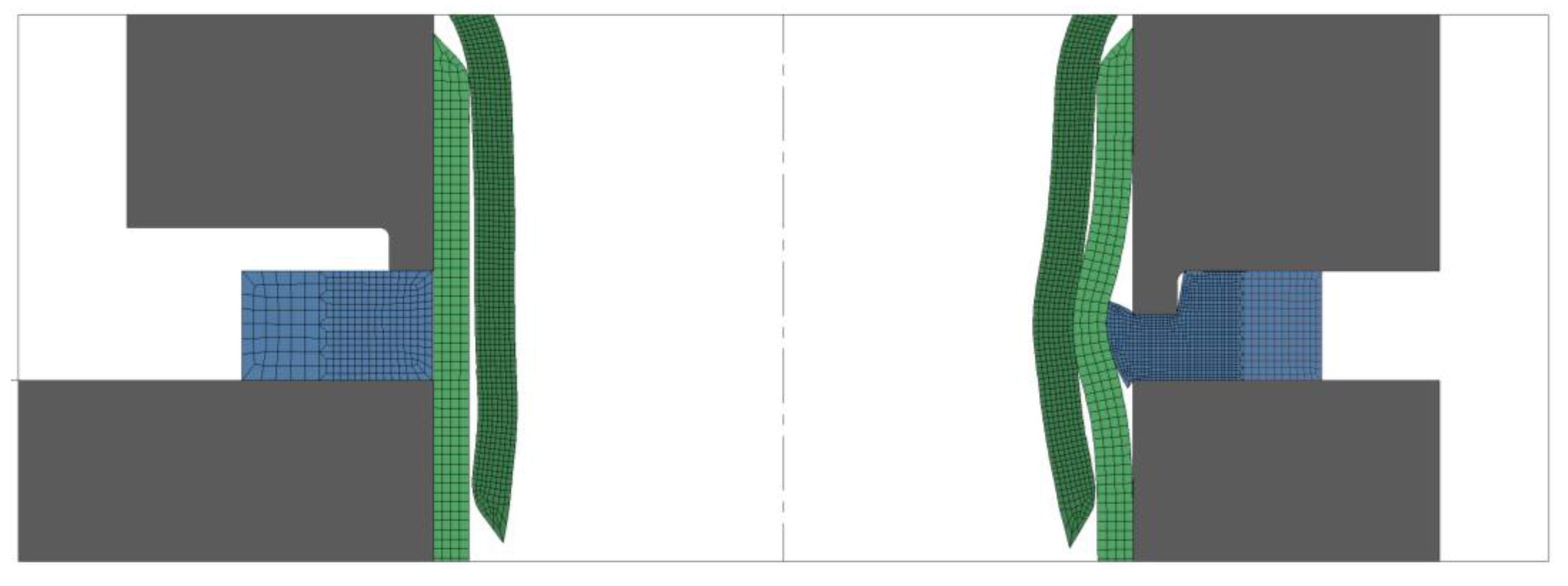
Analysis of the Optimal Surface Contact between the Tubes
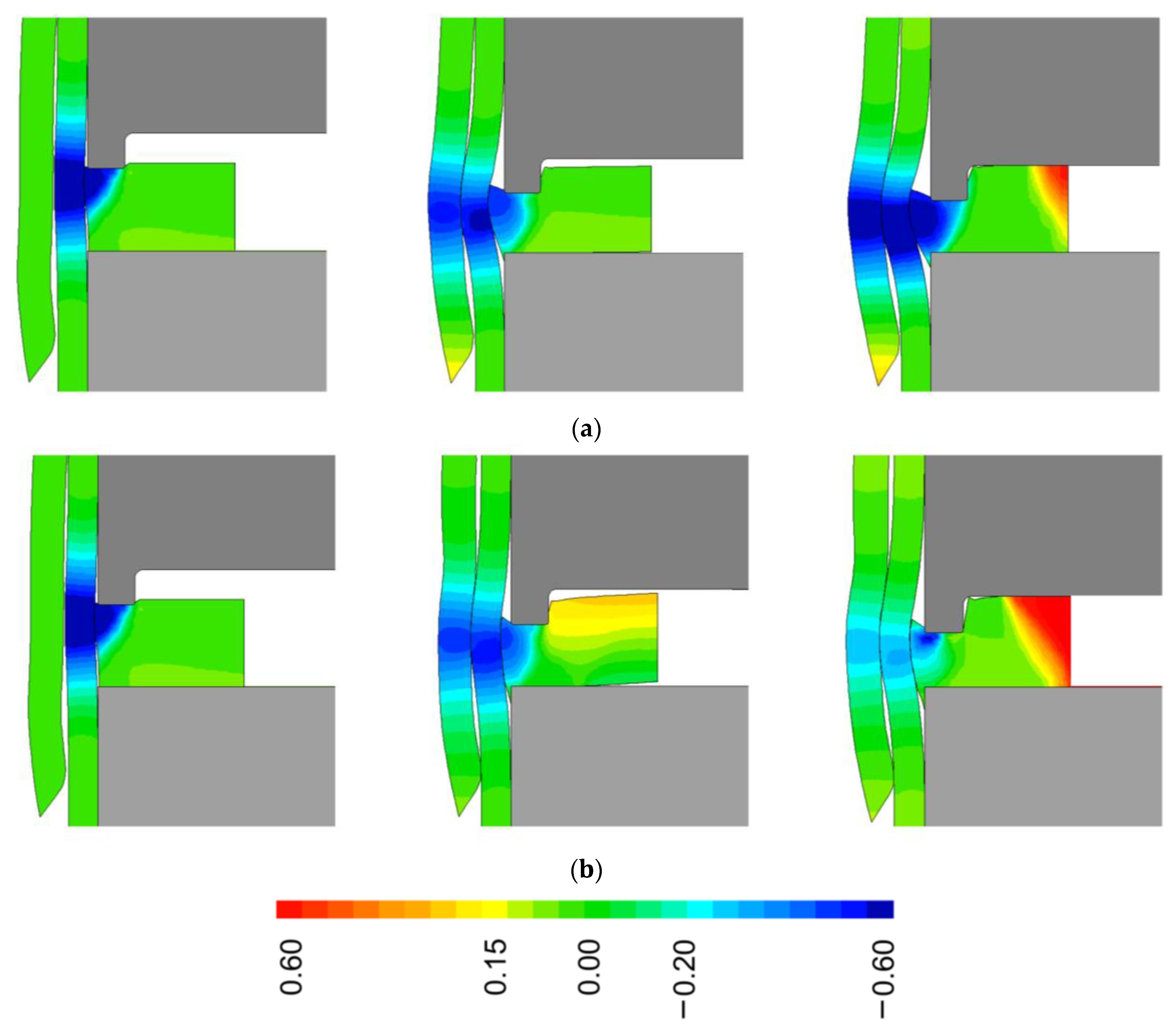
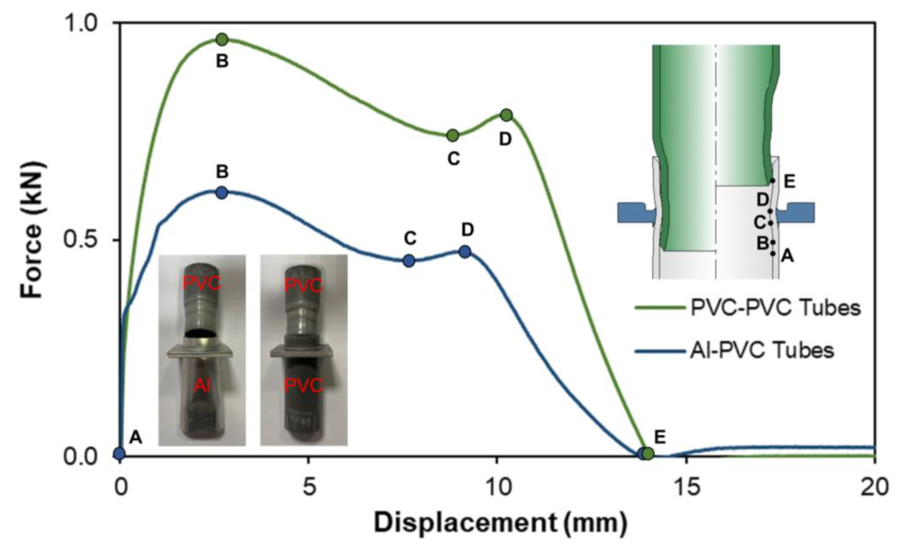
The tube-to-tube joining process consists, at the first stage, of the axial compression of an upper tube, having a chamfered end, against the lower tube with an opposed chamfered end to produce an axial reduction of the upper tube which will then create an adjacent contact surface between the two tubes. Then, a sheet flange is positioned in the middle of the contact interface between the tubes and, after the indentation of that sheet by means of a punch, the sheet material at the adjacent region of the sheet hole is displaced towards the tubes to ensure a proper mechanical interlocking. To ensure a proper contact between the tubes, the penetration depth d p of the upper tube into the lower tube needs to be controlled since this variable will stimulate an adequate contact region which will influence the performance of the joint.
To evaluate the influence of the penetration depth d p in the morphology of the joint, three different lengths—18, 22 and 24 mm—were analyzed. From the results of these tests, presented in Figure 5, different conclusions may be drawn.
Increase in the penetration depth leads to the development of higher radial stress levels as a result of the larger contact region between the inner and outer tube, which offers increased resistance to the deformation produced by the sheet material flow towards the tube walls. The smaller penetration depth of 18 mm produces a very limited contact between the adjacent tube surfaces, with the inner tube not being able to completely brace the outer tube after the sheet flange produces the mechanical interlocking between them (Figure 5a). This will contribute to a quicker detachment of the two tubes when subjected to tensile loads that, in hydraulic applications, can be developed due to a pressure differential. By increasing the penetration depth to 22 mm, a larger contact region is developed and the overall radial stress distribution becomes more intense (Figure 5b). The increase of the penetration depth to 24 mm develops a contact region that extends itself from the contact region between the sheet and tubes to the beginning of the straight lower region of the outer tube where an additional contact is produced. As a result, it can be observed in Figure 5c that larger radial stresses are developed along the tube walls and a stronger mechanical joint is produced. From here, the increase in the penetration depth d p becomes irrelevant since, as will be seen in later sections, the performance of the joint under pull-out loads is provided by the final curvature of the outer tube which forces the inner tube to reduce its diameter, thus eliminating its contact with the straight regions of the inner surface of the lower tube.
Figure 6 presents the force–displacement evolutions of the inner tube reduction process for different material combinations up to a penetration depth of 24 mm. It can be seen that after the initial force peak, the force increases slightly as the inner tube diameter continues to be reduced until a maximum value is reached once the penetration depth is around 18 mm, when the force starts to slightly reduce again up to a constant value that results from the friction forces developed between the tube walls.

4. Discussion

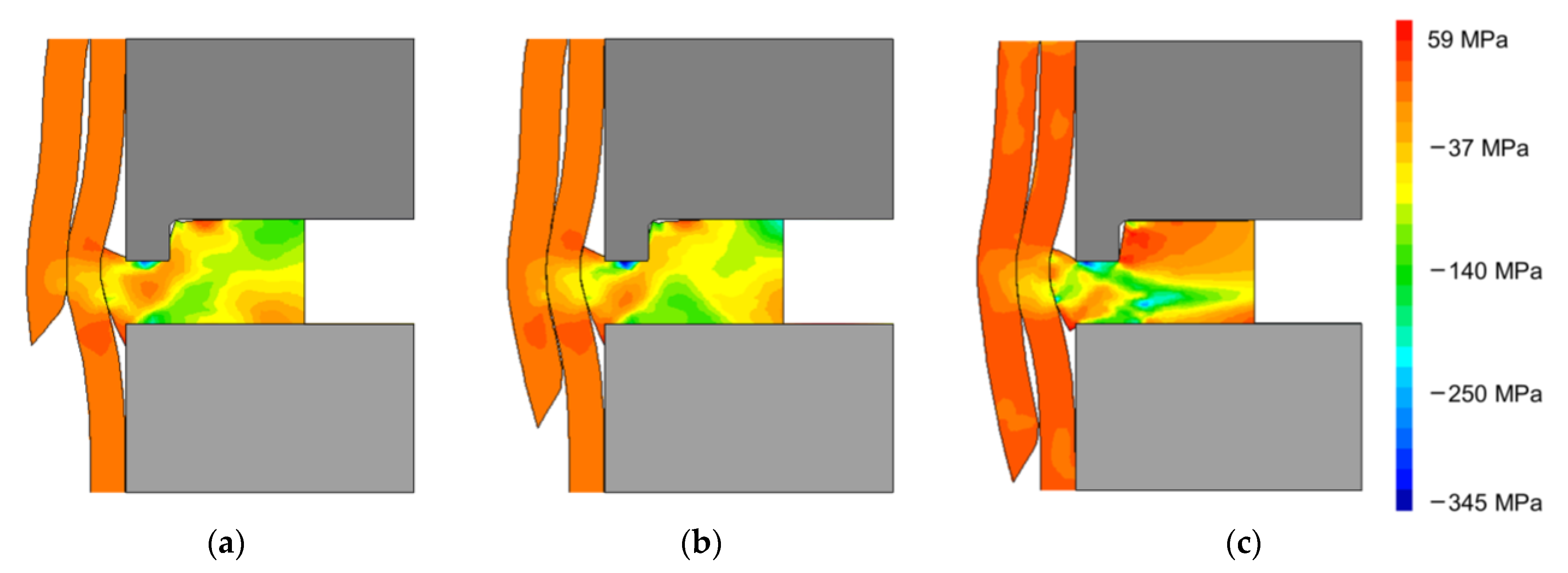
Mechanisms behind the Joint and Their Influence on the Overall Performance

After the definition of the penetration depth, it becomes necessary to analyze the mechanisms behind the joint and understand how they can influence the destructive performance of the joint when subjected to tensile loads as well as its leak tightness.
The numerical prediction of the effective strain at the end of the tube-to-tube joining process between tubes of both similar and dissimilar materials is presented in Figure 7, where it can be seen that the indentation and injection of the sheet flange produces a larger diameter reduction at the PVC–PVC tube combination—and therefore larger levels of strain hardening are developed—in comparison with the aluminum–PVC tube combination.
In fact, the PVC–PVC tube combination results in a smaller tube beading radius r b of approximately 14.95 mm, in comparison with the tube beading radius r b of approximately 15.82 mm that was verified for the aluminum–PVC tube combination. This observation will have an important influence on the performance of the joint, as will be seen later.
From the connection between two PVC tubes, it is possible to observe that the deformation of the inner PVC tube is larger due to the lower resistance offered by the outer tube to the radial injection produced by the sheet flange. In this case, a predominant inward radial injection of the sheet material is observed as depicted in the normalized radial velocity v r / v 0 of Figure 8a. To ensure the development of a mechanical interlock in the dissimilar material combination, the aluminum tube is placed in direct contact with the sheet flange. After the indentation and consequent injection of the sheet material, the more resistant tube material is able to deform the inner PVC tube, thus reducing its inner diameter. Nevertheless, the deformation levels of the inner PVC tube are now reduced further as a consequence of the higher resistance offered by the outer aluminum tube to the inward radial injection produced by the sheet flange. In turn, a divided material flow is produced at intermediate and final stages of the indentation which forces the sheet to flow outwardly as shown in Figure 8b.
The evolution of force with displacement for the indentation and injection of the sheet flange and subsequent tube joining is presented in Figure 9. The evolutions are very similar since the force for the indentation and injection of the sheet flange accounts for most of the overall force [7], whereas the remaining force is related to that needed to shape the inner tube bead and obtain the mechanical connection.
Small differences can be observed at the regions R1 and R2 of the graph of Figure 9. For region R1 that refers to the initial stage of the injection and indentation process (see Figure 8a,b), the differences between the two tube combinations are minimal. However, at the start of region R2, the differences are more noticeable since the aluminum–PVC tube combination demands higher force levels to the same displacement due to the higher resistance of the aluminum outer tube. This promotes a larger outward material flow which forces the sheet flange to bend and contact with the upper punch wall, thus increasing the overall force in relation to the PVC–PVC tube combination. Finally, the force increases sharply for both tube combinations when the punch wall starts to contact with the sheet flange.
The mechanical interlocking between the two tubes is triggered through the indentation and injection of the sheet flange which creates a strong contact interface between the two tubes. This contact will be more intense depending on the elastic recovery of the materials involved which is produced after tool removal that will force the upper tube material to flow into the outward radial direction against the outer tube and the sheet flange.
As can be seen, the PVC–PVC tube combination produces a smaller inner tube beading radius r b than the aluminum–PVC tube combination, which—in conjunction with the larger strain levels observed for the PVC–PVC combination and the elastic modulus of this material—will develop a stronger mechanical joint. This is demonstrated by the results of the tensile destructive tests presented in the graph of Figure 10, where the PVC–PVC tube combination withstands a pull-out force of around 0.97 kN, significantly higher than the approximately 0.62 kN observed for the aluminum–PVC tube combination.
Initially, the inner tube starts detaching from the outer tube, with the inner tube being forced to reduce its diameter to be able to travel along the interior wall of the outer tube. This translates in a force growth until an initial peak (point B), after which the force starts to decrease slightly as a result of intermittent contact between the surfaces of the tubes (up to point C). As the inner tube is displaced along the curvature of the outer tube at the most deformed region, the contact surface between the tubes rises again and the force increases up to a secondary peak value (point D). Then, the contact between the tubes starts to reduce and the force decreases sharply until the inner tube can be completely detached from the outer tube (point E).
To simulate conditions where the joining technology is applied to hydraulic applications, internal water pressure was applied to both mechanical joints in order to evaluate the leak-tightness of the joint. The force–displacement evolutions of these tests are presented in Figure 11, where it is possible to observe that, as a result of a stronger contact between the surfaces of both PVC tubes, this tube joint is able to withstand a force that is 1 kN higher than for the aluminum–PVC tube-to-tube joint. The maximum forces registered for both cases correspond to pressures between 12 and 15 bar, which are well above the typical operating pressures of 3 or 4 bar to which PVC tubes are normally subjected in water and sewage applications. In both cases, the force grows until a peak where a force drop is registered, at which point water starts to leak from the mechanical joint produced.
The new tube-to-tube joining process offers the possibility of producing a permanent tube joint by means of a sheet flange as shown in Figure 12. The thin-walled tube assembly can then be easily attached by its flange to other already-existent elements in applications where, for example, deflection of the tube joint is to be avoided.

5. Conclusions

The concepts of indentation and injection were successfully extended to the production of tube joints by means of a sheet flange. The process is developed in two separate stages, starting with the radial reduction of one of the tubes as it is compressed against another tube, followed by the indentation and injection of a sheet flange that secures both tubes together by the adjacent contact surfaces generated during the tube reduction stage.
From the analysis of the influence of the penetration depth of the upper tube into the lower tube, it was concluded that proper contact pressures (radial stresses) are developed with a penetration depth of 24 mm, which will produce a mechanical joint with adequate performance to tensile loads and capable of ensuring water tightness.
Larger diameter reduction and strain levels were verified for the mechanical connections between PVC tubes due to their lower resistance to the deformation produced by the sheet flange material. A stronger contact between the tubes is then produced, that will allow this mechanical joint to withstand larger values of force before detachment of the joint starts to occur. The tube-to-tube joint made from PVC tubes also revealed better water tightness performance, where the leakage was verified for values above the typical operating pressure, which allows us to conclude that the joint can be safely utilized in hydraulic applications.
Although the performance of the aluminum–PVC tube joint is lower than that of the PVC–PVC tube connection, a sound joint was still produced between those dissimilar materials, the choice of which depends on the force and energy requirements of a given application.
Overall, the new tube joining process has the capability of producing a permanent joint in which its flange can be utilized for a non-permanent connection of the tube assembly to other structures.

Author Contributions

Conceptualization, R.M.A.; data curation, R.M.A.; formal analysis, R.M.A. and L.M.A.; investigation, R.M.A. and L.M.A.; methodology, R.M.A.; supervision, R.M.A.; validation, R.M.A. and L.M.A.; writing—original draft, R.M.A.; writing—review and editing, R.M.A. and L.M.A. All authors have read and agreed to the published version of the manuscript.

Funding

This research was supported by Fundação para a Ciência e a Tecnologia of Portugal and IDMEC under LAETA-UIDB/50022/2020.

Institutional Review Board Statement

Not applicable.

Informed Consent Statement

Not applicable.

Data Availability Statement

Not applicable.

Acknowledgments

The authors would like to acknowledge the contribution of Miguel Sousa during both the numerical and experimental work. Also, the authors would like to thank the support provided by IDMEC and Fundação para a Ciência e a Tecnologia of Portugal.

Conflicts of Interest

The authors declare no conflict of interest. The funders had no role in the design of the study; in the collection, analyses, or interpretation of data; in the writing of the manuscript; or in the decision to publish the results.

References

  1. Kleiner, M.; Geiger, M.; Klaus, A. Manufacturing of lightweight components by metal forming. CIRP Ann. Manuf. Technol. 2003, 52, 521–542. [Google Scholar] [CrossRef]
  2. Mori, K.-I.; Bay, N.; Fratini, L.; Micari, F.; Tekkaya, A.E. Joining by plastic deformation. CIRP Ann. Manuf. Technol. 2013, 62, 673–694. [Google Scholar] [CrossRef]
  3. Groche, P.; Wohletz, S.; Brenneis, M.; Pabst, C.; Resch, F. Joining by forming—A review on joint mechanisms, applications and future trends. J. Mater. Process. Technol. 2014, 214, 1972–1994. [Google Scholar] [CrossRef]
  4. Hahn, M.; Gies, S.; Tekkaya, A.E. Light enough or go lighter? Mater. Des. 2019, 163, 107545. [Google Scholar] [CrossRef]
  5. Meschut, G.; Merklein, M.; Brosius, A.; Drummer, D.; Fratini, L.; Füssel, U.; Gude, M.; Homberg, W.; Martins, P.A.F.; Bobbert, M.; et al. Review on mechanical joining by plastic deformation. J. Adv. Join. Process. 2022, 5, 100113. [Google Scholar] [CrossRef]
  6. Buffa, G.; Fratini, L.; La Commare, U.; Römisch, D.; Wiesenmayer, S.; Wituschek, S.; Merklein, M. Joining by forming technologies: Current solutions and future trends. Int. J. Mater. Form. 2022, 15, 27. [Google Scholar] [CrossRef]
  7. Meschut, G.; Merklein, M.; Brosius, A.; Bobbert, M. Mechanical joining in versatile process chains. Prod. Eng. 2022, 16, 187–191. [Google Scholar] [CrossRef]
  8. Gonçalves, A.; Alves, L.M.; Martins, P.A.F. Tube joining by asymmetric plastic instability. J. Mater. Process. Technol. 2014, 214, 132–140. [Google Scholar] [CrossRef]
  9. Silva, C.M.A.; Alves, L.M.; Nielsen, C.V.; Martins, P.A.F. Environmentally friendly joining of tubes by their ends. J. Clean. Prod. 2015, 87, 777–786. [Google Scholar] [CrossRef]
  10. Zhang, Q.; Jin, K.; Mu, D. Tube/tube joining technology by using rotary swaging forming method. J. Mater. Process. Technol. 2014, 214, 2085–2094. [Google Scholar] [CrossRef]
  11. Alves, L.M.; Afonso, R.M.; Silva, C.M.A.; Martins, P.A.F. Joining sandwich composite panels to tubes. Proc. Inst. Mech. Eng. 2019, 233, 1472–1481. [Google Scholar] [CrossRef]
  12. Alves, L.M.; Reis, T.J.; Afonso, R.M.; Martins, P.A.F. Single-stroke attachment of sheets to tube ends made from dissimilar materials. Materials 2021, 14, 815. [Google Scholar] [CrossRef] [PubMed]
  13. Alves, L.M.; Afonso, R.M.; Martins, P.A.F. Joining by forming of polymer-metal sheet-tube connections. Proc. Inst. Mech. Eng. 2020, 234, 938–946. [Google Scholar] [CrossRef]
  14. Alves, L.M.; Afonso, R.M.; Silva, F.L.R.; Martins, P.A.F. Deformation-assisted joining of sheets to tubes by annular sheet squeezing. Materials 2019, 12, 3909. [Google Scholar] [CrossRef] [Green Version]
  15. Alves, L.M.; Afonso, R.M.; Silva, F.L.R.; Martins, P.A.F. Mechanical joining of sheets to tubes by squeeze-grooving. Proc. Inst. Mech. Eng. 2020, 234, 120–129. [Google Scholar] [CrossRef]
  16. Wang, P.-Y.; Jin, J.-G.; Wan, G.-H.; Zhang, C.-S.; Wang, Y.-C.; Xiang, N.; Zhao, X.-N.; Wang, Z.-J. An improved method for manufacturing sheet-tube connection structure by double-sided annular sheet squeezing. J. Adv. Manuf. Technol. 2022, 120, 829–842. [Google Scholar] [CrossRef]
  17. Nielsen, C.V.; Zhang, W.; Alves, L.M.; Bay, N.; Martins, P.A.F. Coupled Finite Element Flow Formulation. In Modeling of Thermo-Electro-Mechanical Manufacturing Processes; Springer: London, UK, 2013; pp. 11–36. [Google Scholar]
  18. Raghava, R.S.; Caddell, R.M. A macroscopic yield criterion for crystalline polymers. Int. J. Mech. Sci. 1973, 15, 967–974. [Google Scholar] [CrossRef] [Green Version]
  19. Caddell, R.M.; Raghava, R.S.; Atkins, A.G. Pressure dependent yield criteria for polymers. Mater. Sci. Eng. 1974, 13, 113–120. [Google Scholar] [CrossRef]
Figure 1. Schematic representation of tube joining by a sheet flange connection: (a) PVC tube reduction and (b) joining of the PVC and aluminum tubes by indentation and injection of the sheet flange with the correspondent photograph of the joint.
Jmmp 07 00012 g001
Figure 2. Effective stress–strain curves of the supplied materials with schematics of the mechanical characterization tests.
Jmmp 07 00012 g002
Figure 3. Detail of the finite element model after the upper tube reduction at the start of the sheet flange indentation (left) and at the end of the mechanical joining process (right). A mechanical connection between two PVC tubes by means of the aluminum sheet flange is depicted.
Jmmp 07 00012 g003
Figure 4. Initial specimen example (a) to assess the performance of the mechanical joint to (b) pull-out loads and (c) leak tightness.
Jmmp 07 00012 g004
Figure 5. Distribution of radial stress for a PVC–PVC tube combination for different penetration depths dp: (a) 18 mm, (b) 22 mm and (c) 24 mm.
Jmmp 07 00012 g005
Figure 6. Experimental force–displacement evolution for the inner tube reduction of PVC–PVC and aluminum–PVC combinations up to a penetration depth dp of 24 mm.
Jmmp 07 00012 g006
Figure 7. Distribution of effective strain for a connection between two PVC tubes (left) and an inner tube of PVC and an outer tube of aluminum (right). The respective photograph of each correspondent experimental specimen is also included.
Jmmp 07 00012 g007
Figure 8. Evolution of the normalized radial velocity vr/v0 for (a) two PVC tubes and (b) a PVC–aluminum tube combination at the start, intermediate and final stages of the process.
Jmmp 07 00012 g008
Figure 9. Experimental force–displacement evolutions for two PVC tubes as well as an upper tube of PVC and a lower tube of aluminum.
Jmmp 07 00012 g009
Figure 10. Experimental force–displacement evolutions for two PVC tubes as well as an upper tube of PVC and a lower tube of aluminum.
Jmmp 07 00012 g010
Figure 11. Leak-tightness performance for a PVC–PVC and a PVC–Al tube connection.
Jmmp 07 00012 g011
Figure 12. Example of PVC–Al tube connection produced by a sheet flange, having two holes for subsequent assembly.
Jmmp 07 00012 g012
Table 1. Main parameters for the tubes and sheet flange at different stages of the joining process as depicted in Figure 1.
Tubes
r 0 (mm) t 0 (mm) α (°) d p (mm)
161.54518, 22, 24
Sheets
t s (mm) l (mm) d (mm)h (mm)
5222
Disclaimer/Publisher’s Note: The statements, opinions and data contained in all publications are solely those of the individual author(s) and contributor(s) and not of MDPI and/or the editor(s). MDPI and/or the editor(s) disclaim responsibility for any injury to people or property resulting from any ideas, methods, instructions or products referred to in the content.

