


Friction Stir Weldability at High Welding Speed of Two Structural High Pressure Die Casting Aluminum Alloys

 ,
,  , ,
, ,
Abstract
1. Introduction
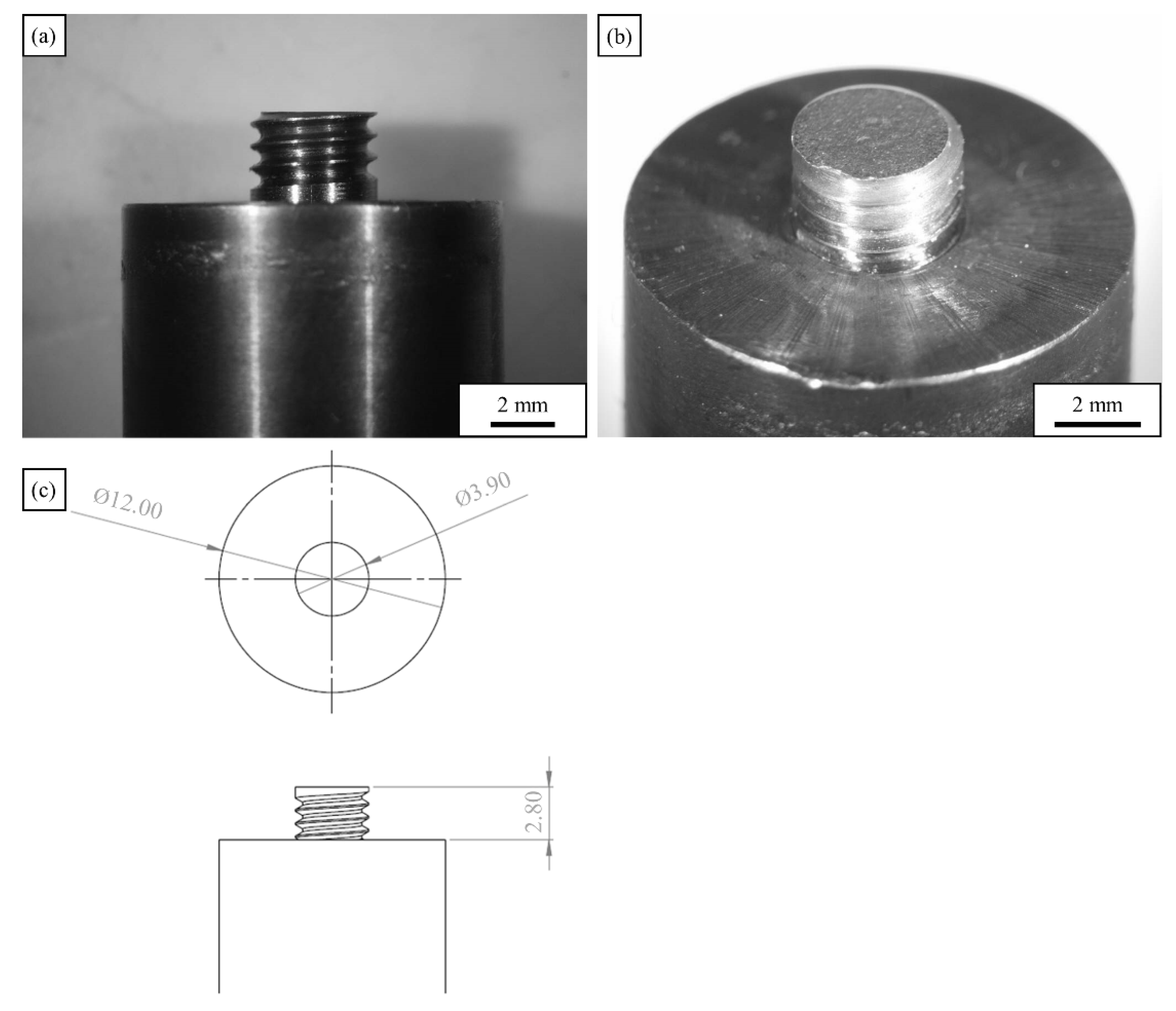
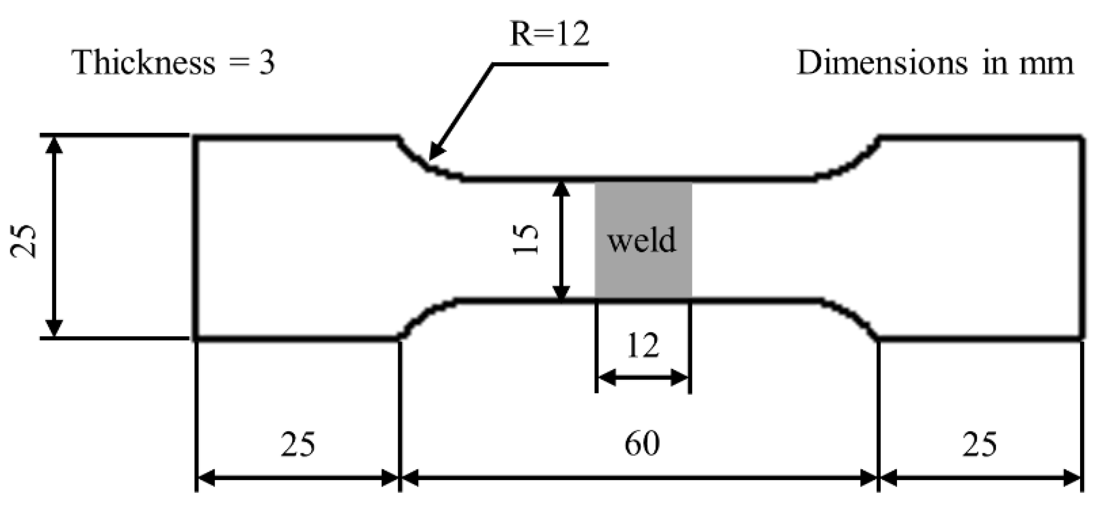
2. Experimental Procedure
3. Results and Discussion
3.1. Microstructure: Base materials
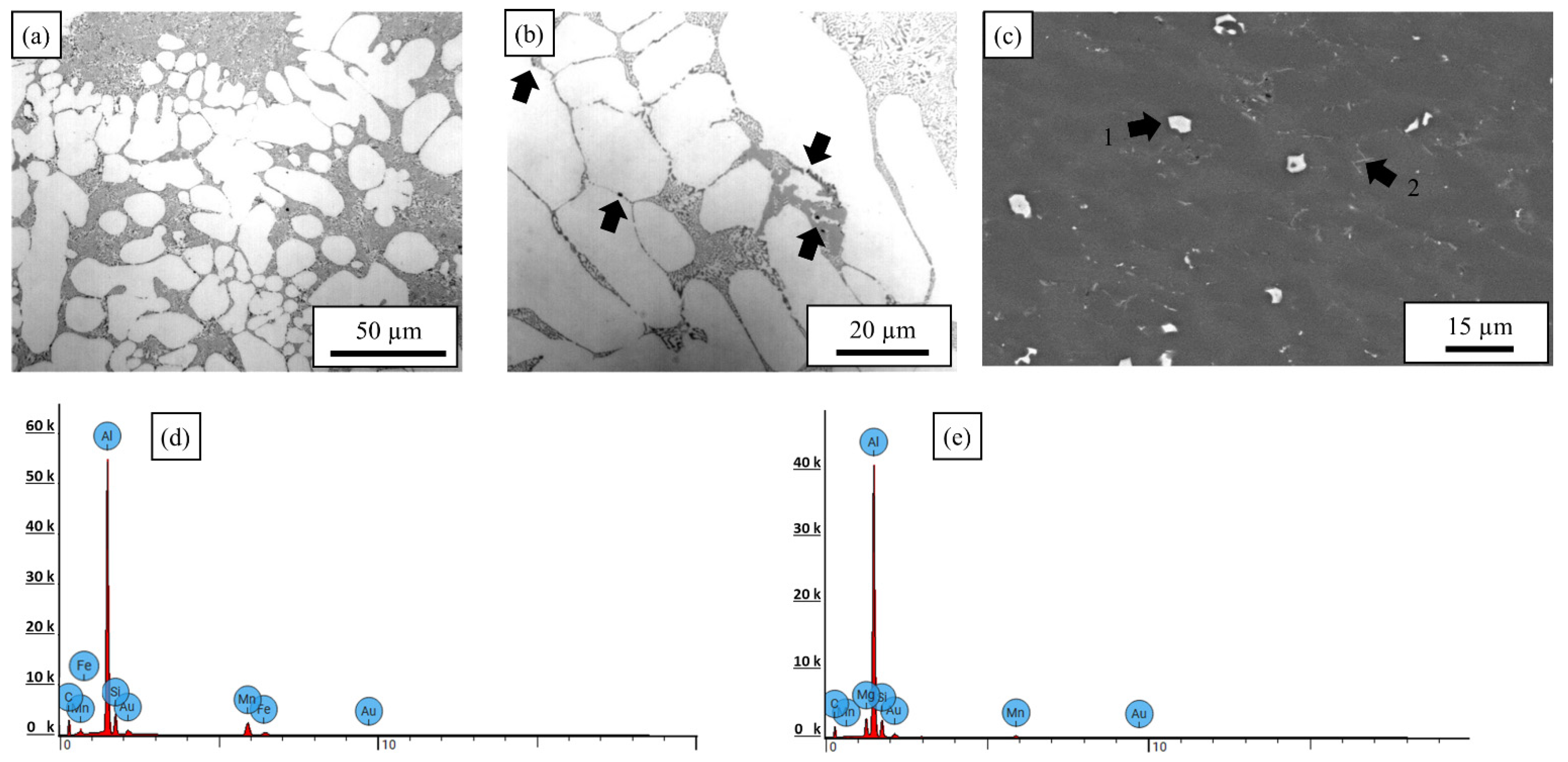
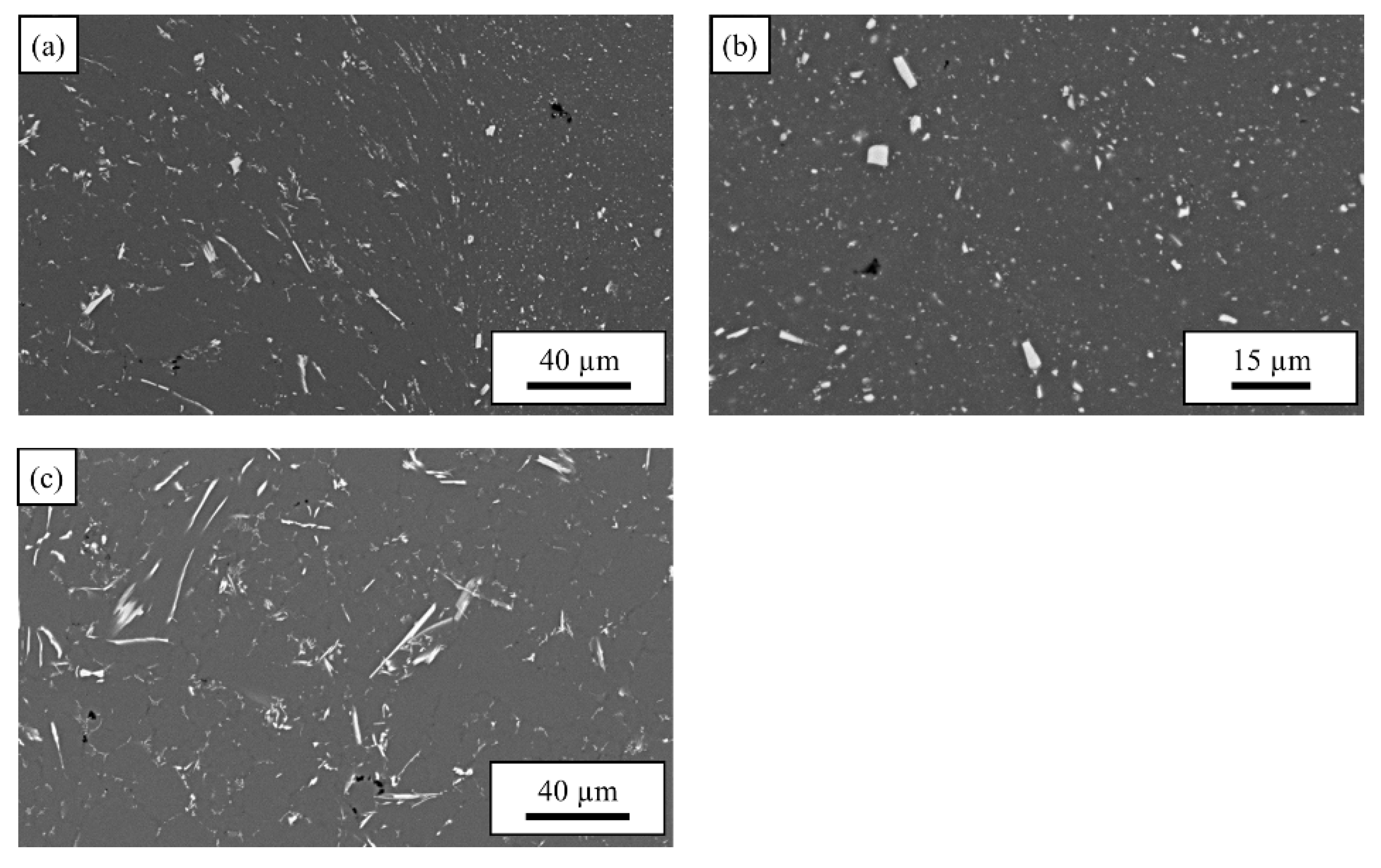
3.1.1. AlSi10MnMg
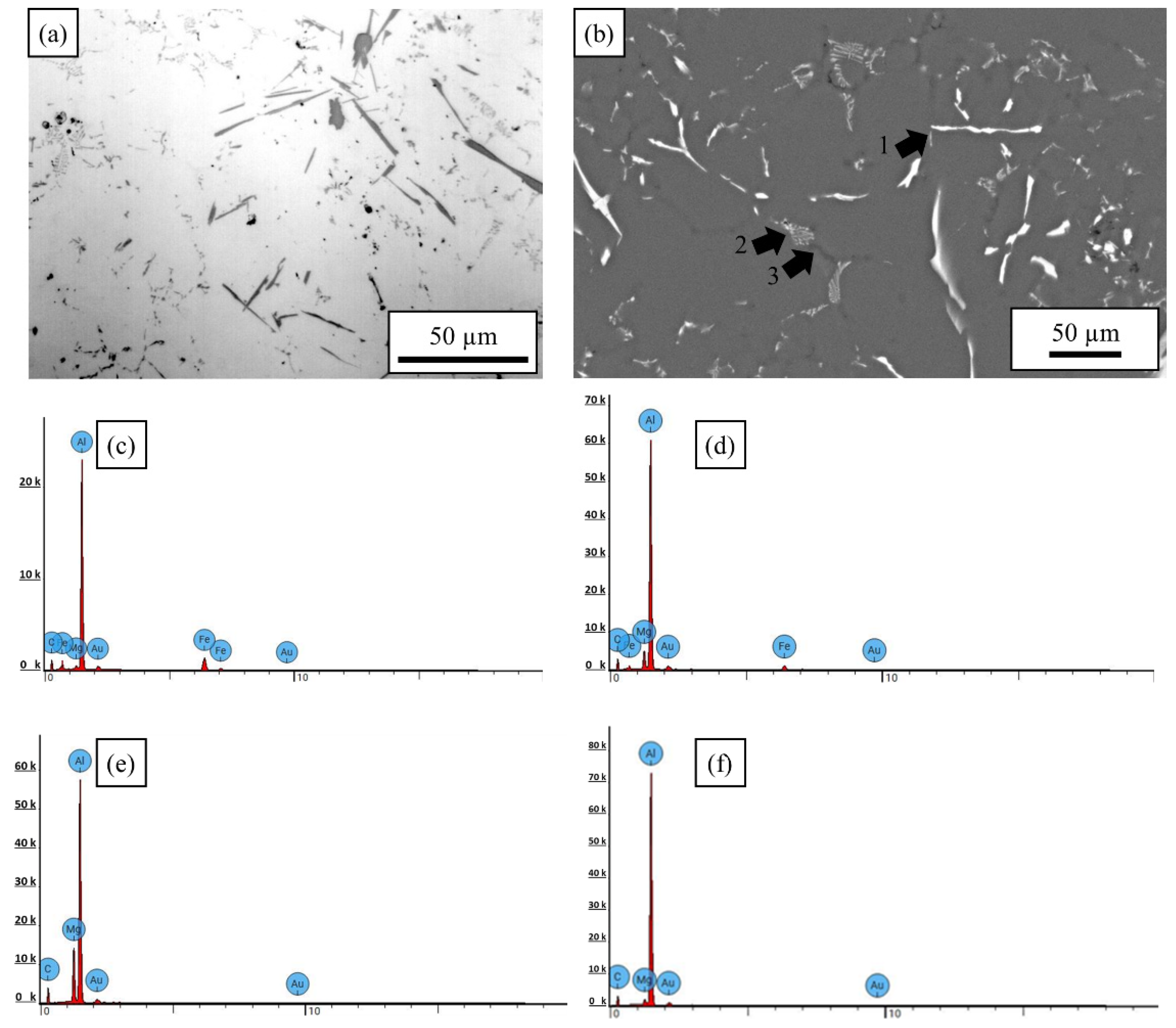
3.1.2. AlMg4Fe2
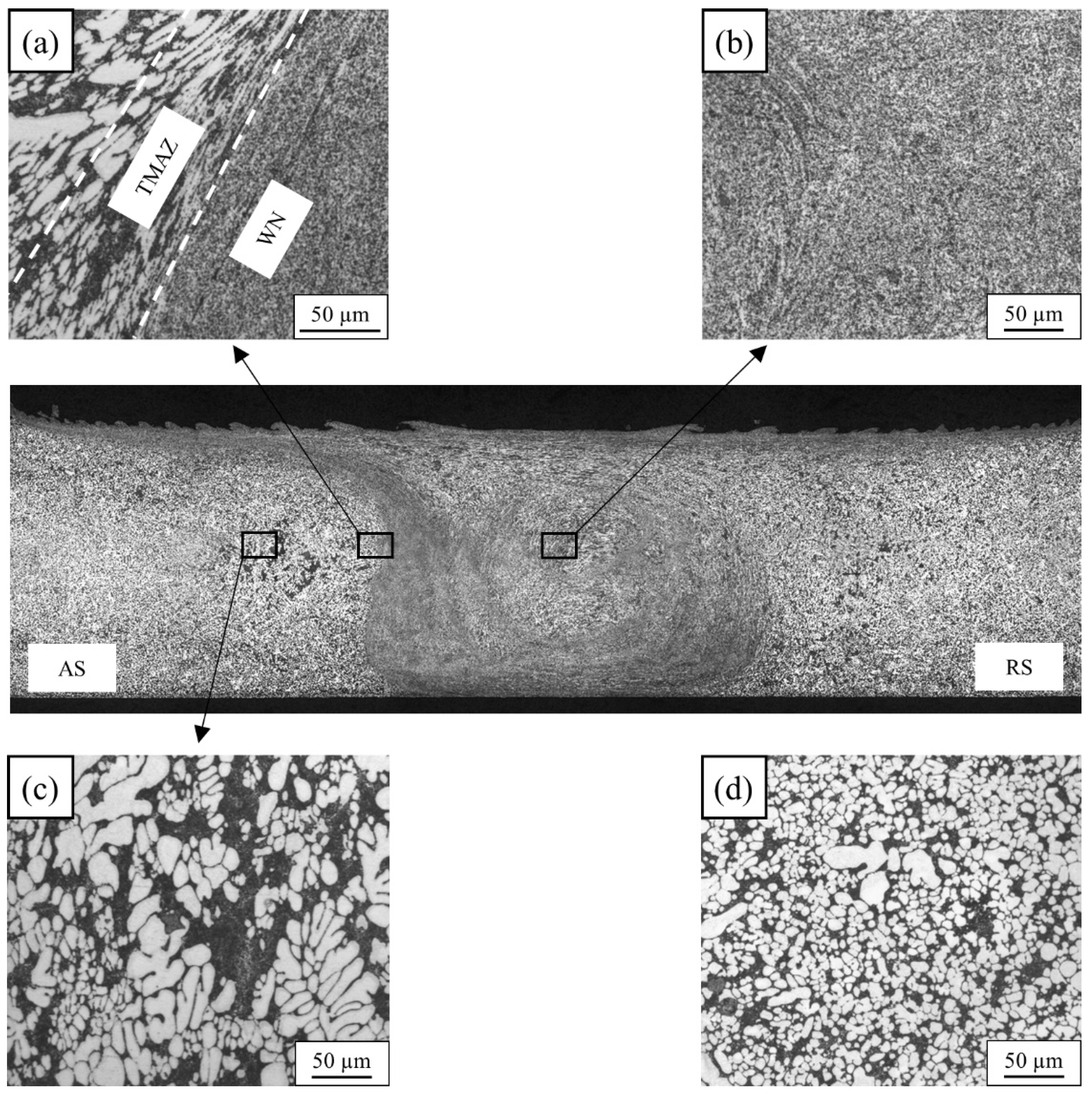
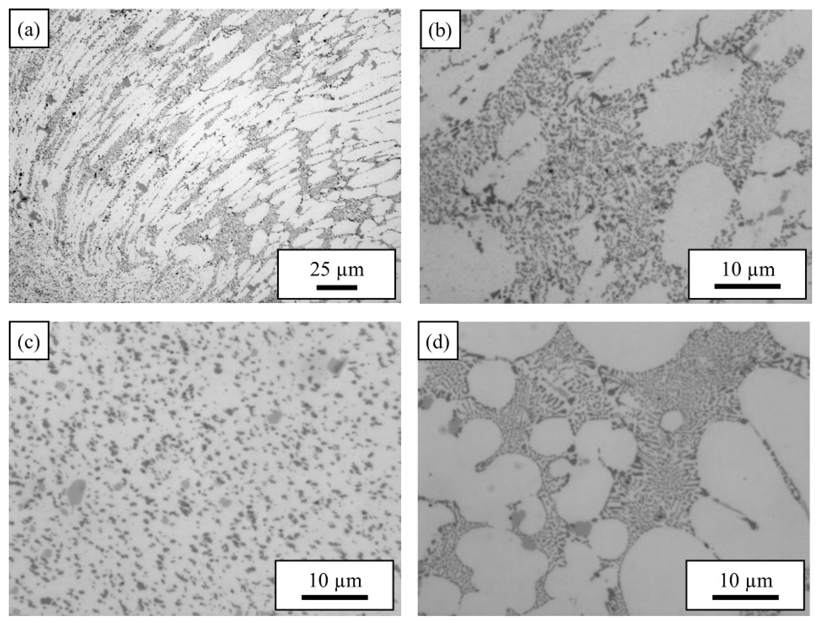
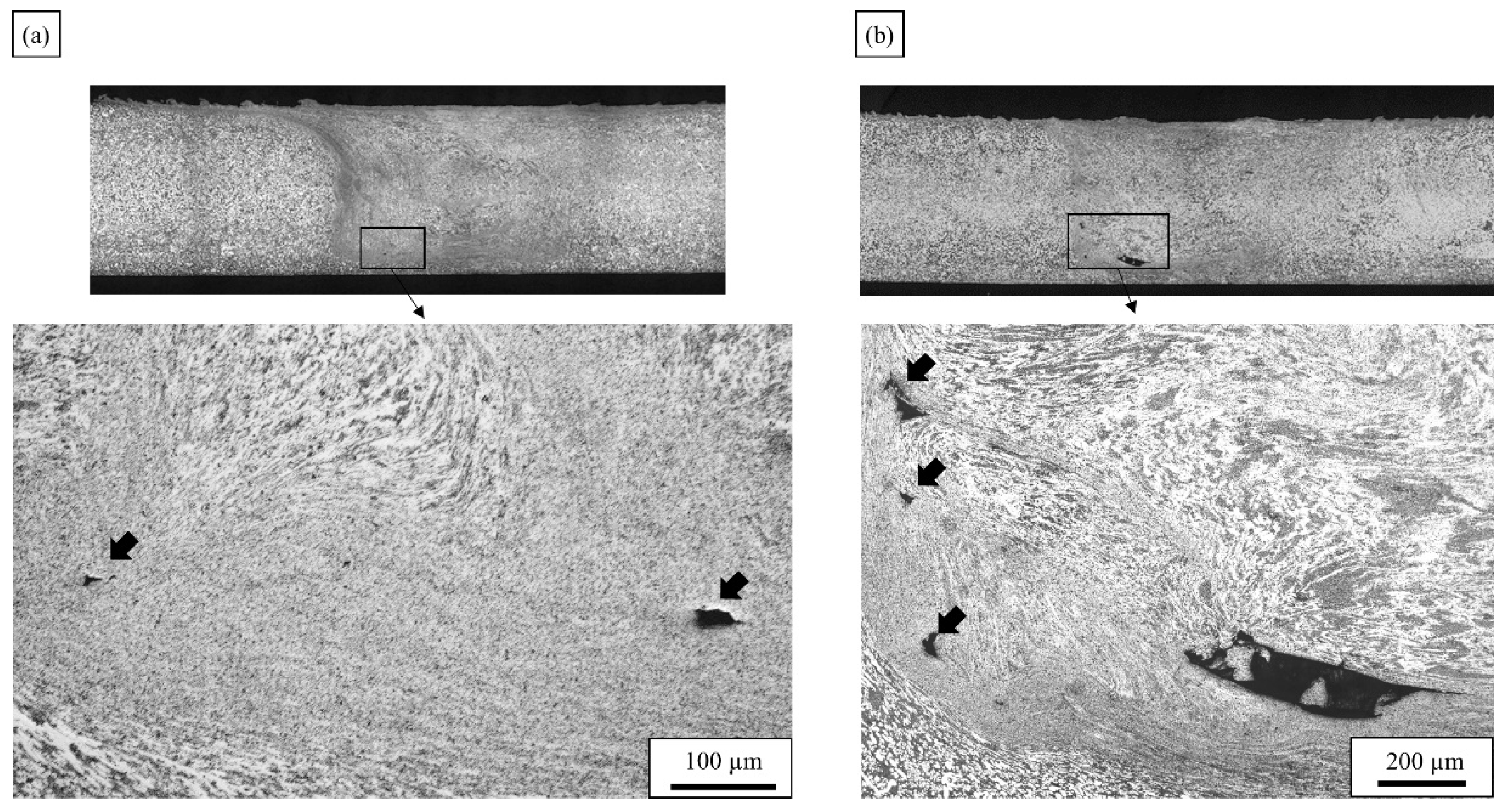
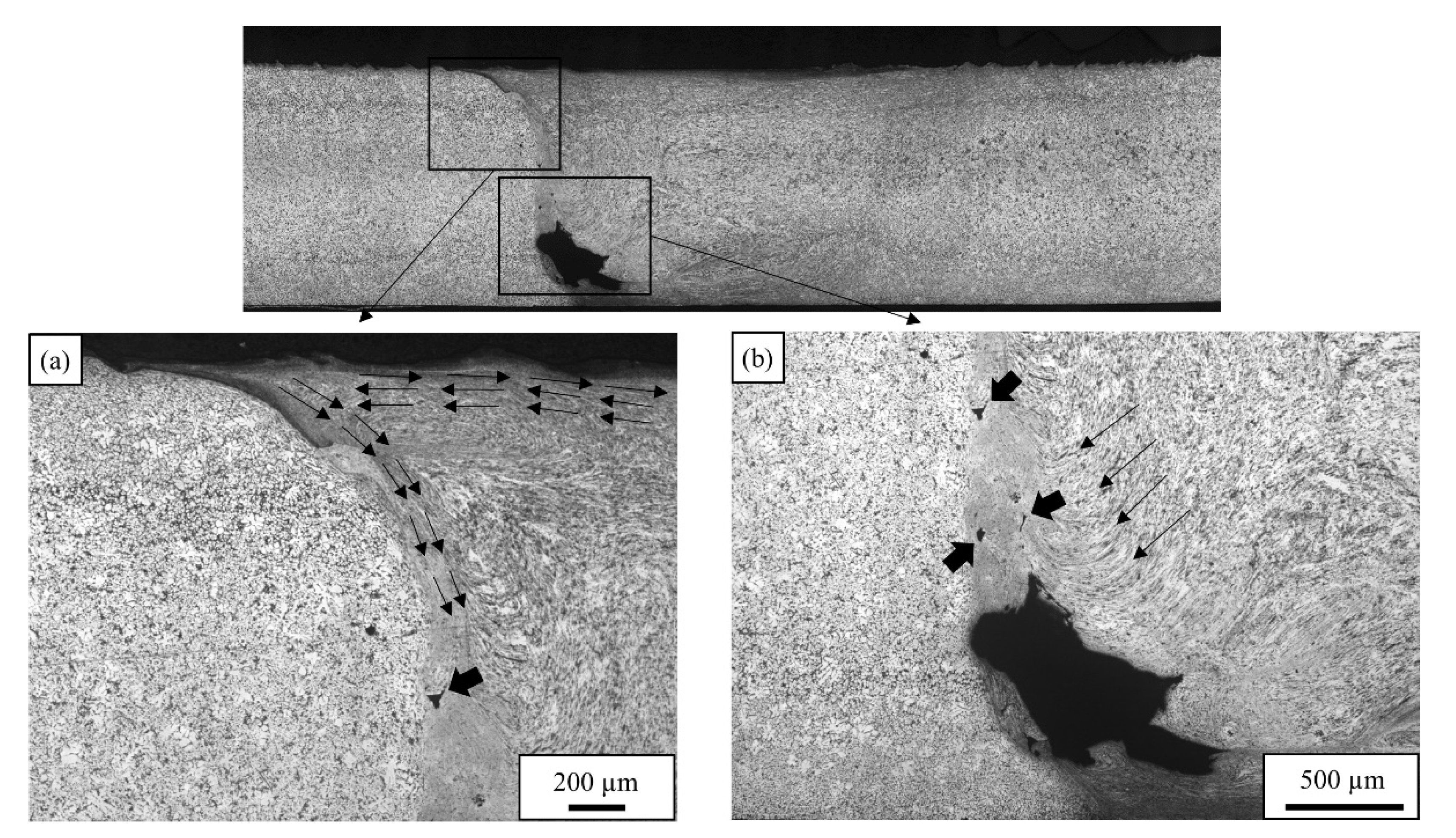
3.2. Microstructure: Material Flow Influence on Weld Formation
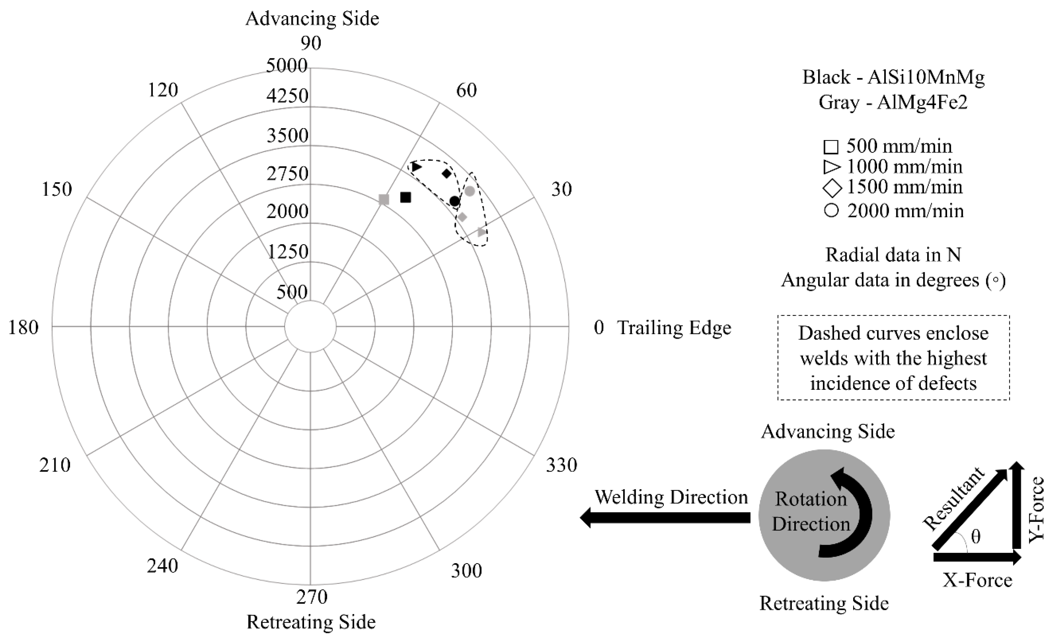
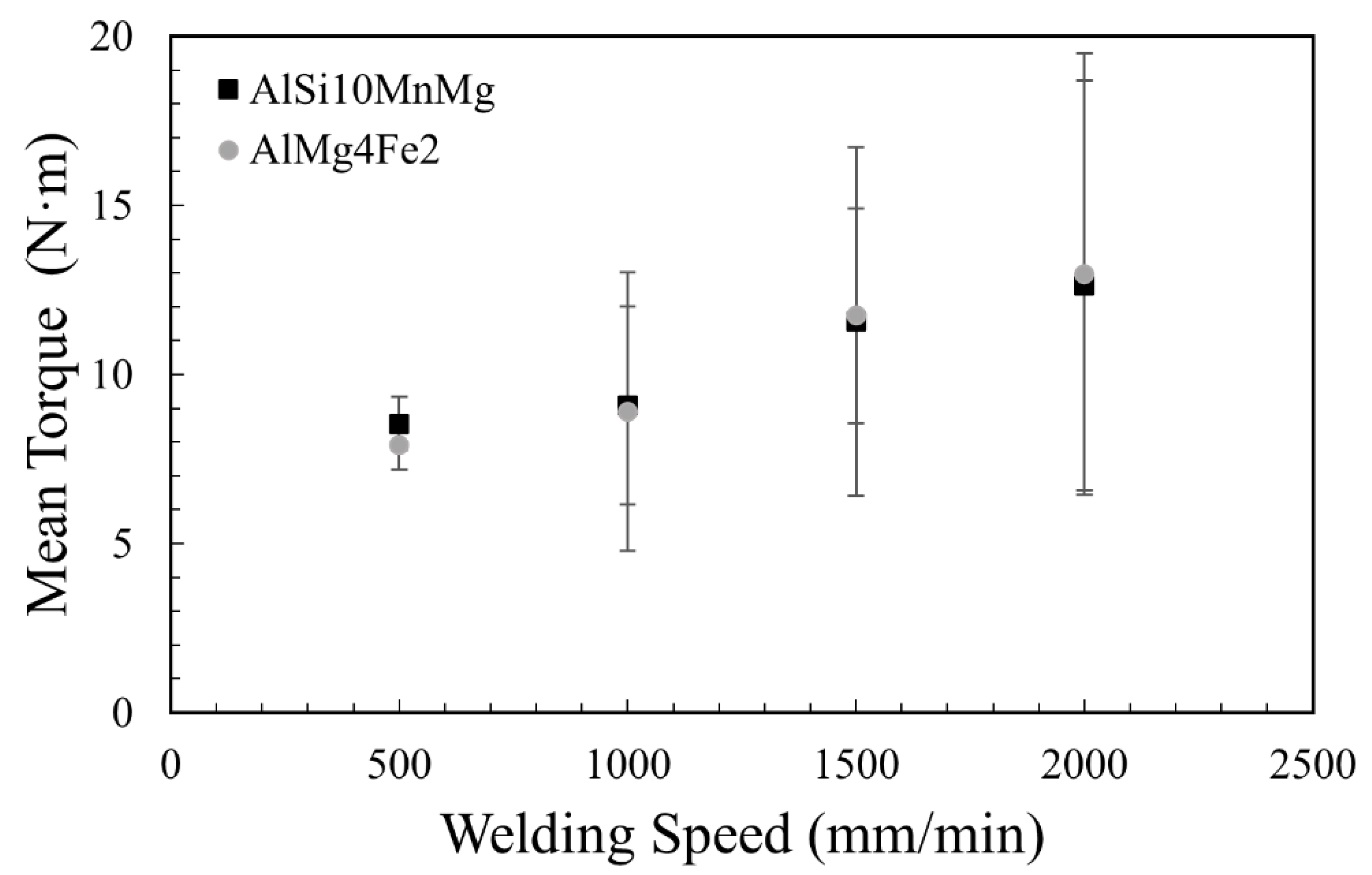
3.3. Process Forces and Torque during FSW
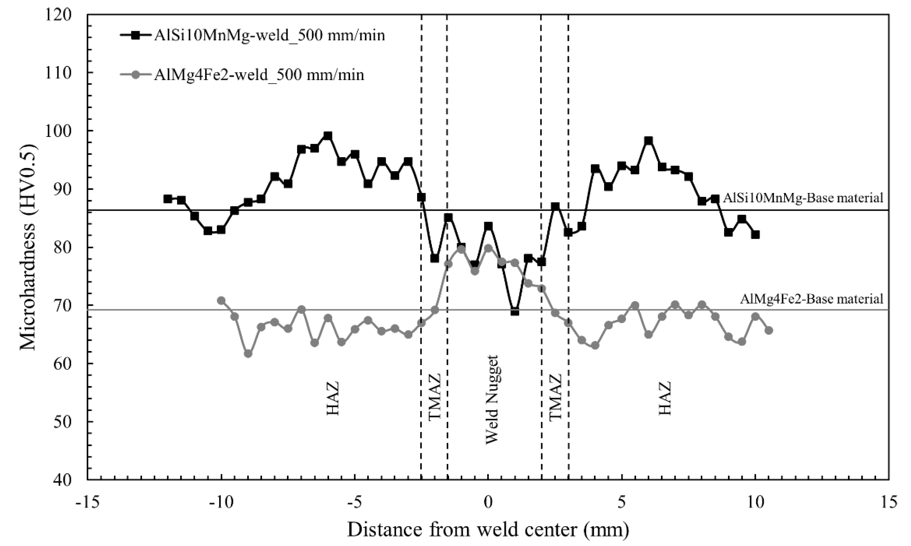
3.4. Mechanical Properties: Microhardness Measurements and Tensile Tests
4. Conclusions
- As a general trend, increasing the welding speed increases the magnitude of the force imparted on the FSW tool. At higher welding speed, the frictional heat is lower and the material has greater resistance to the FSW tool motion. However, the presence of defects, such as cavities or lack of fill, diminishes the magnitude of this force due to the reduction of the plasticized material volume.
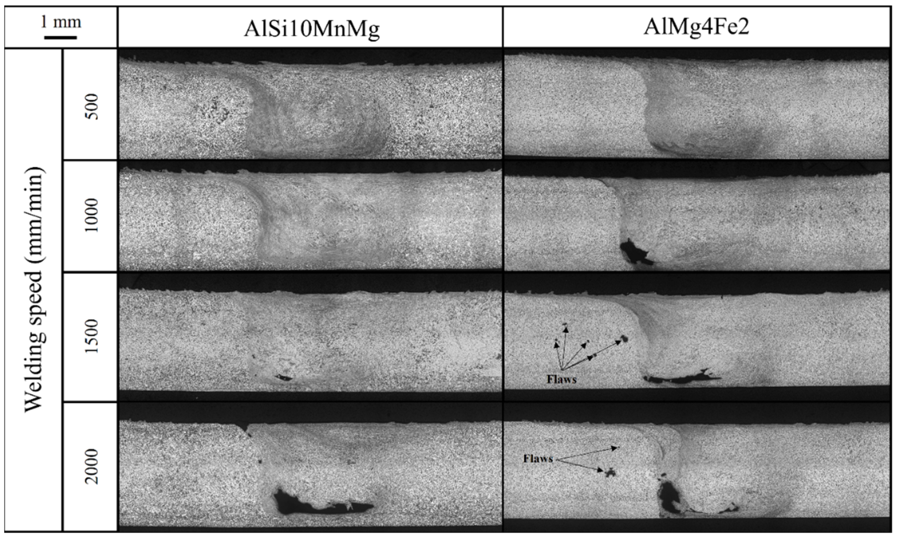
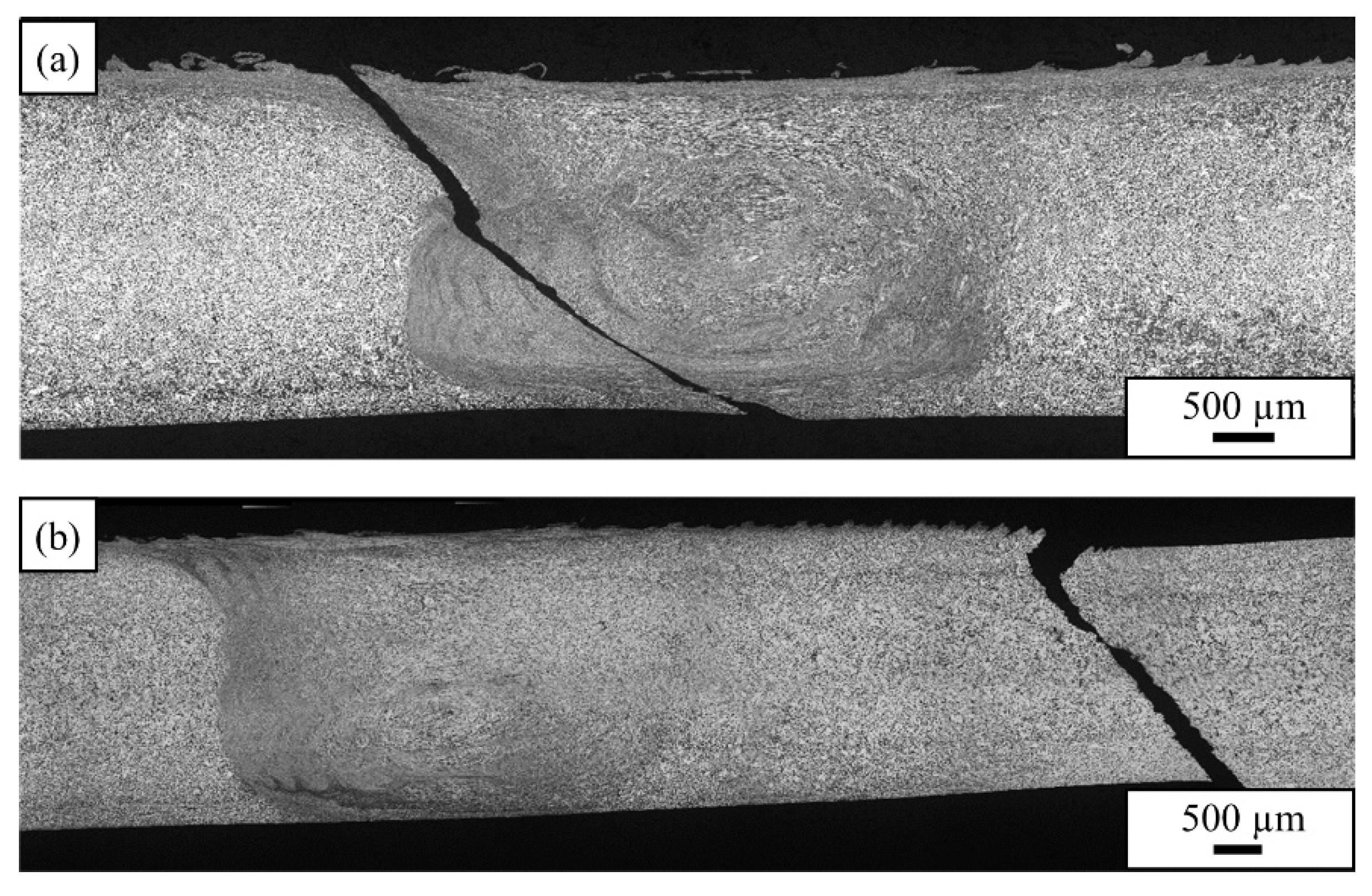
- AlSi10MnMg VPDC alloy shows a lower incidence of FSW defects than AlMg4Fe2 VPDC alloy at all welding speeds investigated. The defects are found at the bottom of the WN and/or near the border between the TMAZ and WN at the advancing side.
- AlSi10MnMg alloy is hardened in HAZ and softened in the middle of the FSW zone. This behavior is associated to the evolution of Mg2Si strengthening precipitates and the coarser Si eutectic observed in the WN area. While AlMg4Fe is slightly softened in HAZ and strengthened by deformation in the middle of FSW zone.
- At a welding speed of 500 mm/min, a high joint efficiency was obtained in both alloys in terms of ultimate tensile strength. The joint efficiency was higher for AlMg4Fe2 than for AlSi10MnMg, at 99% and 92%, respectively.
Author Contributions
Funding
Data Availability Statement
Conflicts of Interest
References
- Sankaran, K.K.; Mishra, R.S. Chapter 4—Aluminum Alloys. Dependence of Castability and Mechanical Properties on Composition and Microstructure of Aluminum Alloys. In Metallurgy and Design of Alloys with Hierarchical Microstructures; Sankaran, K.K., Mishra, R.S., Eds.; Elsevier: Amsterdam, The Netherlands, 2017; pp. 57–176. ISBN 978-0-12-812068-2. [Google Scholar]
- Giampieri, A.; Ling-Chin, J.; Ma, Z.; Smallbone, A.; Roskilly, A.P. A Review of the Current Automotive Manufacturing Practice from an Energy Perspective. Appl. Energy 2020, 261, 114074. [Google Scholar] [CrossRef]
- Kumar, R.R.; Alok, K. Adoption of Electric Vehicle: A Literature Review and Prospects for Sustainability. J. Clean. Prod. 2020, 253, 119911. [Google Scholar] [CrossRef]
- Hirsch, J. Recent Development in Aluminium for Automotive Applications. Trans. Nonferrous Met. Soc. China 2014, 24, 1995–2002. [Google Scholar] [CrossRef]
- Casarotto, F.; Franke, A.J.; Franke, R. 6—High-Pressure Die-Cast (HPDC) Aluminium Alloys for Automotive Applications. In Advanced Materials in Automotive Engineering; Rowe, J., Ed.; Woodhead Publishing: Boston, UK, 2012; pp. 109–149. ISBN 978-1-84569-561-3. [Google Scholar]
- RHEINFELDEN ALLOYS GmbH & Co. KG Home Page. Available online: https://rheinfelden-alloys.eu/wp-content/uploads/2018/09/rheinfelden_alloys_structural_casts_2018.pdf (accessed on 6 December 2022).
- High Integrity Die Casting Processes|Wiley. Available online: https://www.wiley.com/en-us/High+Integrity+Die+Casting+Processes-p-9780471201311 (accessed on 4 October 2022).
- Niklas, A.; Baquedano, A.; Orden, S.; Noguès, E.; Da Silva, M.; Fernández-Calvo, A.I. Microstructure and Mechanical Properties of a New Secondary AlSi10MnMg(Fe) Alloy for Ductile High Pressure Die Casting Parts for the Automotive Industry. Key Eng. Mater. 2016, 710, 244–249. [Google Scholar] [CrossRef]
- Trudonoshyn, O.; Rehm, S.; Randelzhofer, P.; Körner, C. Improvement of the High-Pressure Die Casting Alloy Al-5.7Mg-2.6Si-0.7Mn with Zn Addition. Mater. Charact. 2019, 158, 109959. [Google Scholar] [CrossRef]
- Prach, O.; Trudonoshyn, O.; Randelzhofer, P.; Körner, C.; Durst, K. Effect of Zr, Cr and Sc on the Al–Mg–Si–Mn High-Pressure Die Casting Alloys. Mater. Sci. Eng. A 2019, 759, 603–612. [Google Scholar] [CrossRef]
- Sigworth, G.K.; Donahue, R.J. The Metallurgy of Aluminum Alloys for Structural High-Pressure Die Castings. Int. Metalcast. 2021, 15, 1031–1046. [Google Scholar] [CrossRef]
- Chen, Z.W.; Jahedi, M.Z. Die Erosion and Its Effect on Soldering Formation in High Pressure Die Casting of Aluminium Alloys. Mater. Des. 1999, 20, 303–309. [Google Scholar] [CrossRef]
- Pries, H.; Rethmeier, M.; Wiesner, S.; Wohlfahrt, H. Laser- Und Elektronenstrahlschweißen von Aluminium-Druckguss; DVS, Ed.; Schweißen und Schneiden: Essen, Germany, 2002. [Google Scholar]
- Teichmann, F.; Müller, S.; Dilger, K. The Influence of Ambient Pressure during Laser Beam Welding of Aluminium High Pressure Die Castings on the Occurrence of Weld Bead Porosity. In Proceedings of the Lasers in Manufacturing Conference 2017, LiM 2017, Munich, Germany, 26–29 June 2017. The German Scientific Laser Society (WLT). [Google Scholar]
- Kah, P.; Rajan, R.; Martikainen, J.; Suoranta, R. Investigation of Weld Defects in Friction-Stir Welding and Fusion Welding of Aluminium Alloys. Int. J. Mech. Mater. Eng. 2015, 10, 26. [Google Scholar] [CrossRef]
- Thomas, W.M.; Nicholas, E.D. Friction Stir Welding for the Transportation Industries. Mater. Des. 1997, 18, 269–273. [Google Scholar] [CrossRef]
- Bernard, D.; Hattingh, D.G.; Goosen, W.E.; James, M.N. High Speed Friction Stir Welding of 5182-H111 Alloy: Temperature and Microstructural Insights into Deformation Mechanisms. Met. Mater. Int. 2020, 27, 2821–2836. [Google Scholar] [CrossRef]
- Jayaraman, M.; Balasubramanian, V. Effect of Process Parameters on Tensile Strength of Friction Stir Welded Cast A356 Aluminium Alloy Joints. Trans. Nonferrous Met. Soc. China 2013, 23, 605–615. [Google Scholar] [CrossRef]
- Tajiri, A.; Uematsu, Y.; Kakiuchi, T.; Tozaki, Y.; Suzuki, Y.; Afrinaldi, A. Effect of Friction Stir Processing Conditions on Fatigue Behavior and Texture Development in A356-T6 Cast Aluminum Alloy. Int. J. Fatigue 2015, 80, 192–202. [Google Scholar] [CrossRef]
- Alidokht, S.A.; Abdollah-zadeh, A.; Soleymani, S.; Saeid, T.; Assadi, H. Evaluation of Microstructure and Wear Behavior of Friction Stir Processed Cast Aluminum Alloy. Mater. Charact. 2012, 63, 90–97. [Google Scholar] [CrossRef]
- Qin, Q.; Zhao, H.; Li, J.; Zhang, Y.; Su, X. Microstructure and Mechanical Properties of Friction Stir Processed Al−Mg2Si Alloys. Trans. Nonferrous Met. Soc. China 2020, 30, 2355–2368. [Google Scholar] [CrossRef]
- Escobar, J.; Gwalani, B.; Olszta, M.; Silverstein, J.; Overman, N.; Bergmann, L.; dos Santos, J.F.; Staron, P.; Maawad, E.; Klusemann, B.; et al. Multimodal Analysis of Spatially Heterogeneous Microstructural Refinement and Softening Mechanisms in Three-Pass Friction Stir Processed Al-4Si Alloy. J. Alloys Compd. 2021, 887, 161351. [Google Scholar] [CrossRef]
- Kim, Y.G.; Fujii, H.; Tsumura, T.; Komazaki, T.; Nakata, K. Effect of Welding Parameters on Microstructure in the Stir Zone of FSW Joints of Aluminum Die Casting Alloy. Mater. Lett. 2006, 60, 3830–3837. [Google Scholar] [CrossRef]
- Kashaev, N.; Ventzke, V.; Çam, G. Prospects of Laser Beam Welding and Friction Stir Welding Processes for Aluminum Airframe Structural Applications. J. Manuf. Process. 2018, 36, 571–600. [Google Scholar] [CrossRef]
- Wang, G.; Zhao, Y.; Hao, Y. Friction Stir Welding of High-Strength Aerospace Aluminum Alloy and Application in Rocket Tank Manufacturing. J. Mater. Sci. Technol. 2018, 34, 73–91. [Google Scholar] [CrossRef]
- Aldanondo, E.; Arruti, E.; Alvarez, P.; Echeverria, A. Mechanical and Microstructural Properties of FSW Lap Joints. In Friction Stir Welding and Processing VII; Mishra, R., Mahoney, M.W., Sato, Y., Hovanski, Y., Verma, R., Eds.; Springer International Publishing: Cham, Switzerland, 2016; pp. 195–203. ISBN 978-3-319-48108-1. [Google Scholar]
- Aldanondo, E.; Vivas, J.; Álvarez, P.; Hurtado, I. Effect of Tool Geometry and Welding Parameters on Friction Stir Welded Lap Joint Formation with AA2099-T83 and AA2060-T8E30 Aluminium Alloys. Metals 2020, 10, 872. [Google Scholar] [CrossRef]
- Ubaid, M.; Bajaj, D.; Mukhopadhyay, A.K.; Siddiquee, A.N. Friction Stir Welding of Thick AA2519 Alloy: Defect Elimination, Mechanical and Micro-Structural Characterization. Met. Mater. Int. 2020, 26, 1841–1860. [Google Scholar] [CrossRef]
- Wen, Q.; Li, W.; Patel, V.; Gao, Y.; Vairis, A. Investigation on the Effects of Welding Speed on Bobbin Tool Friction Stir Welding of 2219 Aluminum Alloy. Met. Mater. Int. 2020, 26, 1830–1840. [Google Scholar] [CrossRef]
- Aldanondo, E.; Vivas, J.; Álvarez, P.; Hurtado, I.; Karanika, A. Friction Stir Welding of AA2099-T83 and AA2060-T8E30 Aluminium Alloys with New Cr-Free Surface Treatments and Sealant Application. Metals 2021, 11, 644. [Google Scholar] [CrossRef]
- Aldanondo, E.; Zubiri, O.; Vivas, J.; Álvarez, P.; Hurtado, I. Fretting Fatigue as a Limiting Factor on the Durability of Friction Stir Welded Lap Joints Using AA2099-T83 and AA2060-T8E30 Aluminium Alloys. J. Manuf. Mater. Process. 2022, 6, 94. [Google Scholar] [CrossRef]
- Torkamani, H.; Vivas Méndez, J.; Lecart, C.; Aldanondo Begiristain, E.; Alvarez Moro, P.; Antti, M.-L. Effect of Rotation Speed and Steel Microstructure on Joint Formation in Friction Stir Spot Welding of Al Alloy to DP Steel. J. Manuf. Mater. Process. 2022, 6, 24. [Google Scholar] [CrossRef]
- Kubit, A.; Wydrzynski, D.; Trzepiecinski, T. Refill Friction Stir Spot Welding of 7075-T6 Aluminium Alloy Single-Lap Joints with Polymer Sealant Interlayer. Compos. Struct. 2018, 201, 389–397. [Google Scholar] [CrossRef]
- Venu, B.; BhavyaSwathi, I.; Raju, L.S.; Santhanam, G. A Review on Friction Stir Welding of Various Metals and Its Variables. Mater. Today Proc. 2019, 18, 298–302. [Google Scholar] [CrossRef]
- Shin, H.-S.; Jung, Y.-C.; Lee, J.-K. Influence of Tool Speeds on Dissimilar Friction Stir Spot Welding Characteristics of Bulk Metallic Glass/Mg Alloy. Met. Mater. Int. 2012, 18, 685–689. [Google Scholar] [CrossRef]
- Gao, P.; Zhang, Y.; Mehta, K.P. Metallurgical and Mechanical Properties of Al–Cu Joint by Friction Stir Spot Welding and Modified Friction Stir Clinching. Met. Mater. Int. 2020, 27, 3085–3094. [Google Scholar] [CrossRef]
- Nandan, R.; DebRoy, T.; Bhadeshia, H.K.D.H. Recent Advances in Friction-Stir Welding—Process, Weldment Structure and Properties. Prog. Mater. Sci. 2008, 53, 980–1023. [Google Scholar] [CrossRef]
- Arbegast, W.J. A Flow-Partitioned Deformation Zone Model for Defect Formation during Friction Stir Welding. Scr. Mater. 2008, 58, 372–376. [Google Scholar] [CrossRef]
- Kumar, K.; Kailas, S.V. The Role of Friction Stir Welding Tool on Material Flow and Weld Formation. Mater. Sci. Eng. A 2008, 485, 367–374. [Google Scholar] [CrossRef]
- Balasubramanian, N.; Gattu, B.; Mishra, R.S. Process Forces during Friction Stir Welding of Aluminium Alloys. Sci. Technol. Weld. Join. 2009, 14, 141–145. [Google Scholar] [CrossRef]
- Hattingh, D.G.; Blignault, C.; van Niekerk, T.I.; James, M.N. Characterization of the Influences of FSW Tool Geometry on Welding Forces and Weld Tensile Strength Using an Instrumented Tool. J. Mater. Process. Technol. 2008, 203, 46–57. [Google Scholar] [CrossRef]
- Reza-E-Rabby, M.; Reynolds, A.P. Effect of Tool Pin Thread Forms on Friction Stir Weldability of Different Aluminum Alloys. Procedia Eng. 2014, 90, 637–642. [Google Scholar] [CrossRef]
- Reza-E-Rabby, M.; Tang, W.; Reynolds, A.P. Effects of Thread Interruptions on Tool Pins in Friction Stir Welding of AA6061. Sci. Technol. Weld. Join. 2018, 23, 114–124. [Google Scholar] [CrossRef]
- Reza-E-Rabby, M.; Reynolds, A.P. Some Effects of Tool Geometric Features on Friction Stir Weld Response Parameters. Sci. Technol. Weld. Join. 2018, 23, 575–584. [Google Scholar] [CrossRef]
- Trimble, D.; Monaghan, J.; O’Donnell, G.E. Force Generation during Friction Stir Welding of AA2024-T3. CIRP Ann. 2012, 61, 9–12. [Google Scholar] [CrossRef]
- Meeting, M. Metals and Materials Society. In Light Metals 1995: Proceedings of the Technical Sessions Presented by the TMS Light Metals Committee at the 124th TMS Annual Meeting, Las Vegas, 12–16 February 1995; Minerals, Metals & Materials Society: Pittsburgh, PA, USA, 1995. [Google Scholar]
- Jacquin, D.; Guillemot, G. A Review of Microstructural Changes Occurring during FSW in Aluminium Alloys and Their Modelling. J. Mater. Process. Technol. 2021, 288, 116706. [Google Scholar] [CrossRef]
- Heidarzadeh, A.; Mironov, S.; Kaibyshev, R.; Çam, G.; Simar, A.; Gerlich, A.; Khodabakhshi, F.; Mostafaei, A.; Field, D.P.; Robson, J.D.; et al. Friction Stir Welding/Processing of Metals and Alloys: A Comprehensive Review on Microstructural Evolution. Prog. Mater. Sci. 2021, 117, 100752. [Google Scholar] [CrossRef]
- Liu, H.J.; Fujii, H.; Nogi, K. Microstructure and Mechanical Properties of Friction Stir Welded Joints of AC4A Cast Aluminium Alloy. Mater. Sci. Technol. 2004, 20, 399–402. [Google Scholar] [CrossRef]
- Padhy, G.K.; Wu, C.S.; Gao, S. Friction Stir Based Welding and Processing Technologies—Processes, Parameters, Microstructures and Applications: A Review. J. Mater. Sci. Technol. 2018, 34, 1–38. [Google Scholar] [CrossRef]
- Da Silva, A.A.M.; Aldanondo, E.; Alvarez, P.; Echeverria, A.; Eiersebner, M. Mechanical and Microstructural Investigation of Dissimilar Resistance and Friction Stir Spot Welds in AA5754-H22 and AA6082-T6 Al Alloys and 22MnB5 Hot-Stamped Boron Steel. In Friction Stir Welding and Processing VI; John Wiley & Sons, Ltd.: Hoboken, NJ, USA, 2011; pp. 389–399. ISBN 978-1-118-06230-2. [Google Scholar]
- Kim, Y.G.; Fujii, H.; Tsumura, T.; Komazaki, T.; Nakata, K. Three Defect Types in Friction Stir Welding of Aluminum Die Casting Alloy. Mater. Sci. Eng. A 2006, 415, 250–254. [Google Scholar] [CrossRef]
- Fonda, R.; Reynolds, A.; Feng, C.R.; Knipling, K.; Rowenhorst, D. Material Flow in Friction Stir Welds. Metall. Mater. Trans. A 2013, 44, 337–344. [Google Scholar] [CrossRef]
- Guerra, M.; Schmidt, C.; McClure, J.C.; Murr, L.E.; Nunes, A.C. Flow Patterns during Friction Stir Welding. Mater. Charact. 2002, 49, 95–101. [Google Scholar] [CrossRef]
- Boldsaikhan, E.; Corwin, E.M.; Logar, A.M.; Arbegast, W.J. The Use of Neural Network and Discrete Fourier Transform for Real-Time Evaluation of Friction Stir Welding. Appl. Soft Comput. 2011, 11, 4839–4846. [Google Scholar] [CrossRef]
- Mishra, D.; Roy, R.B.; Dutta, S.; Pal, S.K.; Chakravarty, D. A Review on Sensor Based Monitoring and Control of Friction Stir Welding Process and a Roadmap to Industry 4.0. J. Manuf. Process. 2018, 36, 373–397. [Google Scholar] [CrossRef]
- Hovanski, Y.; Upadhyay, P.; Carsley, J.; Luzanski, T.; Carlson, B.; Eisenmenger, M.; Soulami, A.; Marshall, D.; Landino, B.; Hartfield-Wunsch, S. High-Speed Friction-Stir Welding to Enable Aluminum Tailor-Welded Blanks. JOM 2015, 67, 1045–1053. [Google Scholar] [CrossRef]


| Chemical Composition wt. % | |||||||||
|---|---|---|---|---|---|---|---|---|---|
| Si | Fe | Mg | Mn | Cu | Ti | Sr | Zn | Be | |
| AlSi10MnMg | 10.0 | 0.14 | 0.30 | 0.68 | <0.040 | 0.078 | 0.013 | <0.030 | <0.030 |
| ±0.4 | ±0.01 | ±0.01 | ±0.05 | - | ±0.007 | ±0.001 | - | - | |
| AlMg4Fe2 | 0.050 | 1.60 | 3.95 | <0.030 | <0.040 | <0.030 | <0.030 | <0.030 | <0.030 |
| ±0.012 | - | ±0.15 | - | - | - | - | - | - | |
| Aluminum Alloy | Average Orientation (θ) With Range |
|---|---|
| AlSi10MnMg | 50° ± 7° |
| AlMg4Fe2 | 41° ± 13° |
| Sample | Ultimate Tensile Strength (MPa) | Elongation (%) | Joint Efficiency in Terms of Ultimate Tensile Strength (%) | Fracture Location |
|---|---|---|---|---|
| AlSi10MnMg-Base material | 290 (±2) | 6.1 (±0.4) | - | - |
| AlSi10MnMg-weld_500 mm/min | 268 (±4) | 4.9 (±0.5) | 92 | Weld Nugget |
| AlMg4Fe2-Base material | 265 (±1) | 16.3 (±0.9) | - | - |
| AlMg4Fe2-weld_500 mm/min | 263 (±2) | 14.1 (±1.2) | 99 | Heat affected Zone |
Publisher’s Note: MDPI stays neutral with regard to jurisdictional claims in published maps and institutional affiliations. |
© 2022 by the authors. Licensee MDPI, Basel, Switzerland. This article is an open access article distributed under the terms and conditions of the Creative Commons Attribution (CC BY) license (https://creativecommons.org/licenses/by/4.0/).
Share and Cite
Vivas, J.; Fernández-Calvo, A.I.; Aldanondo, E.; Irastorza, U.; Álvarez, P. Friction Stir Weldability at High Welding Speed of Two Structural High Pressure Die Casting Aluminum Alloys. J. Manuf. Mater. Process. 2022, 6, 160. https://doi.org/10.3390/jmmp6060160
Vivas J, Fernández-Calvo AI, Aldanondo E, Irastorza U, Álvarez P. Friction Stir Weldability at High Welding Speed of Two Structural High Pressure Die Casting Aluminum Alloys. Journal of Manufacturing and Materials Processing. 2022; 6(6):160. https://doi.org/10.3390/jmmp6060160
Chicago/Turabian StyleVivas, Javier, Ana Isabel Fernández-Calvo, Egoitz Aldanondo, Uxue Irastorza, and Pedro Álvarez. 2022. "Friction Stir Weldability at High Welding Speed of Two Structural High Pressure Die Casting Aluminum Alloys" Journal of Manufacturing and Materials Processing 6, no. 6: 160. https://doi.org/10.3390/jmmp6060160
APA StyleVivas, J., Fernández-Calvo, A. I., Aldanondo, E., Irastorza, U., & Álvarez, P. (2022). Friction Stir Weldability at High Welding Speed of Two Structural High Pressure Die Casting Aluminum Alloys. Journal of Manufacturing and Materials Processing, 6(6), 160. https://doi.org/10.3390/jmmp6060160