Article

A Combination of Alloy Modification and Heat Treatment Strategies toward Enhancing the Properties of LPBF Processed Hot Working Tool Steels (HWTS)

by
Iris Raffeis
1,*,
Frank Adjei-Kyeremeh
1,
Simon Ewald
2,
Johannes Henrich Schleifenbaum
2 and
Andreas Bührig-Polaczek
1
1
Foundry Institute, RWTH Aachen University, Intzestraße 5, 52072 Aachen, Germany
2
Digital Additive Production, RWTH Aachen University, Campus-Boulevard 73, 52074 Aachen, Germany
*
Author to whom correspondence should be addressed.
J. Manuf. Mater. Process. 2022, 6(3), 63; https://doi.org/10.3390/jmmp6030063
Submission received: 29 April 2022 / Revised: 2 June 2022 / Accepted: 4 June 2022 / Published: 10 June 2022

Abstract

:
Hot working tool steels (HWTS) are popular for industrial applications such as injection molding tools, and casting dies because of their high wear resistance, fatigue, strength, and toughness properties, even at elevated temperatures. Conventionally, they go through multi-stage heat treatments in order to attain targeted microstructures. Achieving such microstructures with a laser powder bed fusion (LPBF) process will require tailor-made process parameters since it is characterized by non-equilibrium conditions, non-uniform temperature distribution, and metastable phase formation. Recent advances in the LPBF qualification of 1.2343/4 HWTS have shown commendable results but are still fraught with the limitations of poor ductility or extra post-heat treatment steps. For the industrial competitiveness of LPBF HWTS, the enhancement of strength and ductility and elimination of post processing is critical. Therefore, minimizing retained austenite in the as-built samples through pre-heat treatment or alloying to reduce post heat treatments without sacrificing strength will be economically important for industry. In this work, 1.2343 HWTS and its modified form were LPBF printed both in the as-built, pre- and post-heat-treated conditions. The results are discussed based on the correlations of the powder properties with LPBF—part density, microstructure, and mechanical properties.

1. Introduction

Die manufacturing through conventional processes is not only costly and time-consuming, but also imposes additional challenges including cooling channel design limitations such as the geometrical accuracy of channels and mold cavities, this has a consequential effect on heat dissipation, internal thermal stress, and on the overall mold life [1]. Considering the design freedom of geometry of the laser powder bed fusion (LPBF) process and the ability to shorten lead-time, the LPBF process presents itself as an alternative manufacturing route for die manufacturing, which can address these conventional manufacturing challenges [2].
Hot-work tool steels (HWTS) such as 1.2343 (H11) due to their resistance to soft hardening and thermal fatigue as well as impact loading resistance at elevated temperatures are excellent materials for die casting dies [3]. Conventionally, in order to achieve the requisite properties, these alloys usually undergo multi-step heat treatments such as hardening and tempering to achieve a tempered martensitic microstructure with finely distributed carbides formed from the matrix [4]. Obtaining the requisite material properties by additive manufacturing (LPBF) through skipping as many heat treatment steps as possible will further make the LPBF process a preferred manufacturing route in terms of meeting both the geometric and economic demands associated with the manufacturing of casting dies. H11 is a leaner version of H13 HWTS: carbon (0.33–0.43 wt.%), molybdenum (1.10–1.60 wt.%), and vanadium (0.30–0.60 wt.%) [3]. While H13 has been extensively investigated by either using LPBF [2,5,6,7,8,9] and LMD [10,11,12] AM processes, the H11 has comparatively not been. Through AM (LPBF) processing, H11 can exhibit comparable compressive properties like those of the conventional method, and their modification (C—0.24 wt.%, Cr—3.53 wt.%, Mo—0.95 wt.%, V—0.29 wt.%) can also yield better wear resistance properties [13]. In an experimental study of the H11 alloy by [14], the authors who used the LPBF process successfully fabricated the die-casting dies with conformal cooling channels but paid no particular attention to the microstructure or mechanical properties. They concluded that conformal cooling enhances the surface finish of castings since the need for spray cooling is reduced by high cooling rates of the LPBF process. The authors in [15] studied the heat treatment effects on the microstructure and mechanical properties of the H11 built LPBF samples. Two times post heat treatment (550 °C for 2 h) was performed on both the hardened (austenitized at 1100 °C for 15 min, water quenched) and as-built samples. In the investigations by [16] of LPBF built H11 samples, the hardened (air quenched for 10 min for 910, 960, 1010, 1060 °C) or as-built samples were either once or twice tempered for 2 h at 450, 500, 525, 550, and 600 °C and the microhardness was determined. The authors reportedly found ferritic cellular structures with carbides on its boundaries in the as-built condition. The highest hardness was reported after quenching at 1010 °C and tempering at 500 °C.
In the current investigations, a standard H11/1.2343 HWTS and its modified version were both LPBF printed. The microstructure and mechanical properties of both alloys over a wide range of heat treatment strategies were compared, with the intent that the wide window of heat treatment strategies in this study and their corresponding properties will provide options for trade-off decision making between the application required properties and economical process routes.

2. Materials and Methods

Standard/Commercial H11 powder was obtained from Thyssenkrupp GmbH and with the help of a powder drum mixer, the alloy was modified according to the composition highlighted in Table 1. The chemical composition of both powders, standard and modified, were determined using the inductively coupled plasma optical emission spectroscopy (ICP-OES). Particle size analysis, which was carried out with a Retsch GmbH CAMSIZER X2, recorded the d50, sphericity, aspect ratio of 30.80 µm, 0.808, 0.895 for the modified 1.2343 and 30.1 µm, and 0.913, 0.908 for the standard 1.2343, respectively.
The phase simulations of both alloy compositions were performed with the CALPHAD based software, ThermoCalc using the TCFE10 database. Cuboid shaped samples with dimensions of 10 × 5 × 5 mm3 were printed using the Aconity Mini 3D LPBF printer IPG Photonics YLR 400, F-Theta lens (f = 420 mm, λ = 1030–1080 nm) with a laser spot diameter of 80 µm. A bidirectional XY scanning strategy that turned about 90° on each layer was used during the print jobs. The process parameters for the print job are highlighted in Table 2. The samples were printed under the as-built and preheated conditions (500 °C) for both the standard 1.2343 and modified 1.2343 alloys. All samples chosen from the as-built and preheat treated conditions had a relative density higher than 99.7%. Tempering once or twice for either 2 h, 4 h, or 8 h at 550 °C was conducted on the as-built and preheated samples using the oven manufactured by Nabertherm GmbH Model No. N120/85HA. The tempering at 550 °C for 4 h was compared to 780 °C, 4 h post heat treated samples. The relative densities were determined by the optical method with ImageJ open-source software. The microhardness test (HV 0.5) was performed on all samples. This included the as-built only, preheated only as well as their tempered conditions. The microhardness measurements were conducted using the Buehler microhardness testing equipment MicroMet 5104 according to DIN EN ISO6507-1. All tensile test samples (B4) were built along the Z-axis, machined, and tested at room temperature according to DIN50125 on the INSTRON 8033 tensile testing equipment. All reported tensile strength values were those of three averaged measurements. Samples were etched with 3–5% Nital 120–480 s, depending on the alloy and heat treatment condition. Microstructural characterizations were conducted with both the Zeiss light optical microscope (LOM) and the Zeiss scanning electron microscope (SEM); field emission gun (FEG) with Oxford Instrument Inca X-sight energy dispersive spectroscopy (EDS)/electron backscatter diffraction (EBSD) detectors. Tensile tests were performed on the B4-tensile samples printed in the vertical orientation (Z-axis).

3. Results and Discussions

3.1. Standard 1.2343-Powder

Spherical particles with almost no satellites and d50 of 42.38 µm were observed and measured, respectively (Figure 1). The apparent and tapped density were measured. The mean Hausner ratio was 1.08, a value for excellent flowability. The microstructure showed micro segregations of Mo, Cr, and V on the cell boundaries. Two different phases were detected with EBSD: martensite and about 1.45% of retained austenite (RA).

3.2. Standard 1.2343-As-Built and Preheated LPBF-Test Cuboids

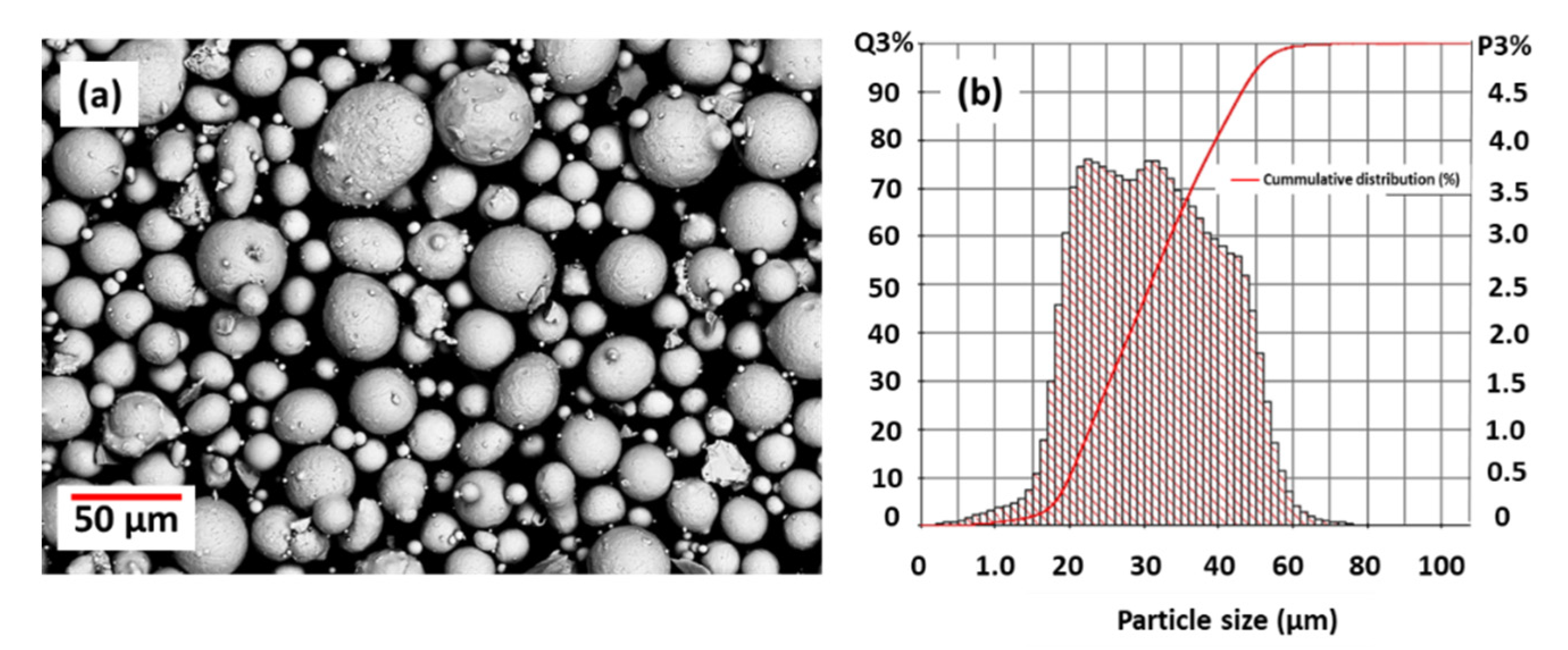
Test cuboids were printed with and without a preheated build plate. Since the microstructure of the powder particles consisted of martensite and some austenite (Figure 1), two different cooling regimens (as-built and preheating) were employed to influence the microstructure. It is known that the cooling rate of the LPBF-process is higher than the cooling rate during atomizing.
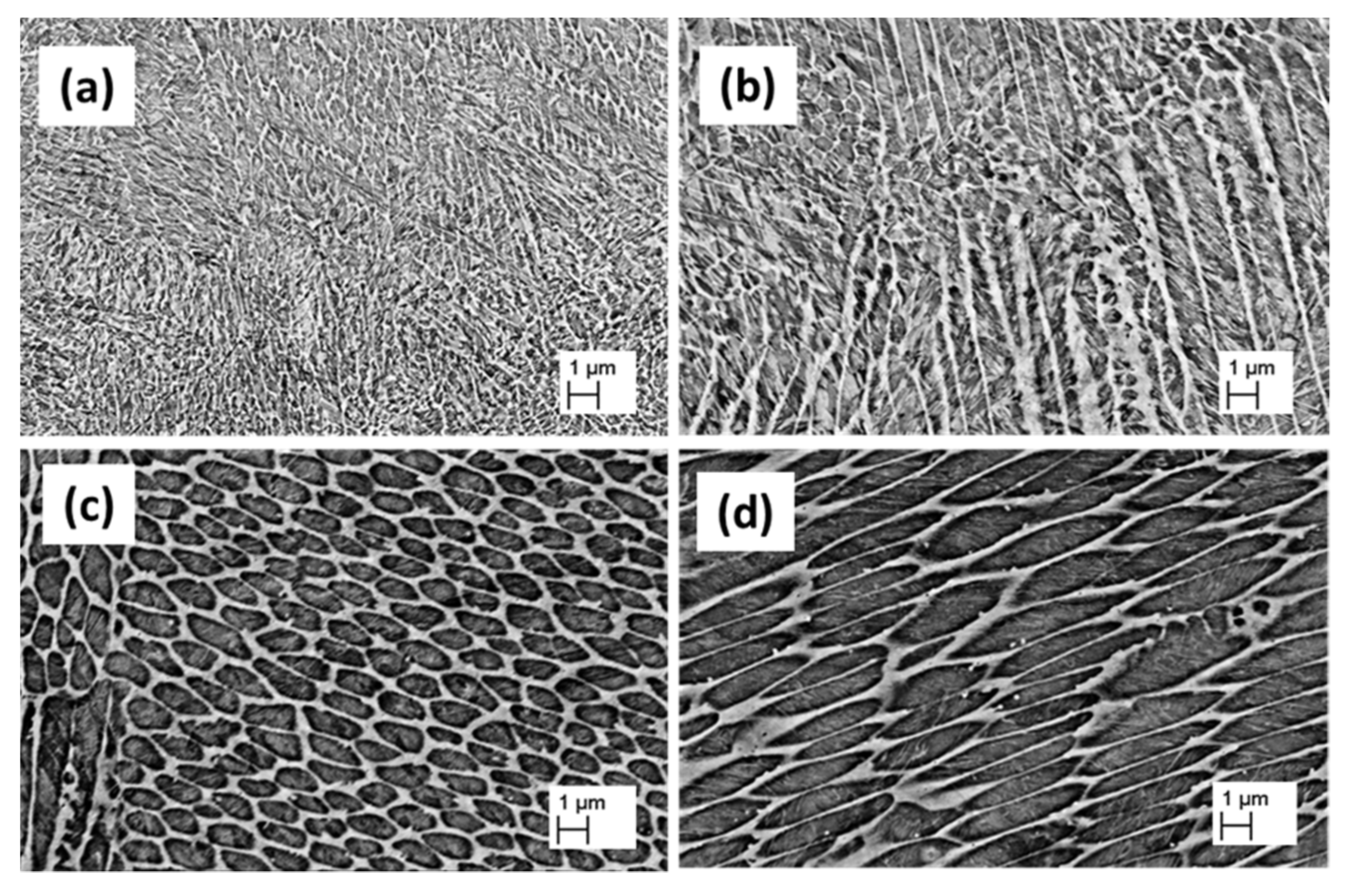
The microstructure of the standard 1.2343 alloy, as shown by the SEM micrographs in Figure 2a,b, revealed cellular dendritic structures both in the as-built and in the preheated condition (Figure 2c,d). These cellular dendritic structures are typical sub-grain solidification microstructural features of hot work tool steels and have been reported by other authors to vary in size under both the LPBF and DED process conditions [4,17]. It appears that the preheat temperature of 500 °C did not significantly alter the cell structure as the microstructure under both conditions appeared similar. The studies by [5,18] equally observed that the different preheating temperatures did not alter the cellular microstructure. It was reported in [
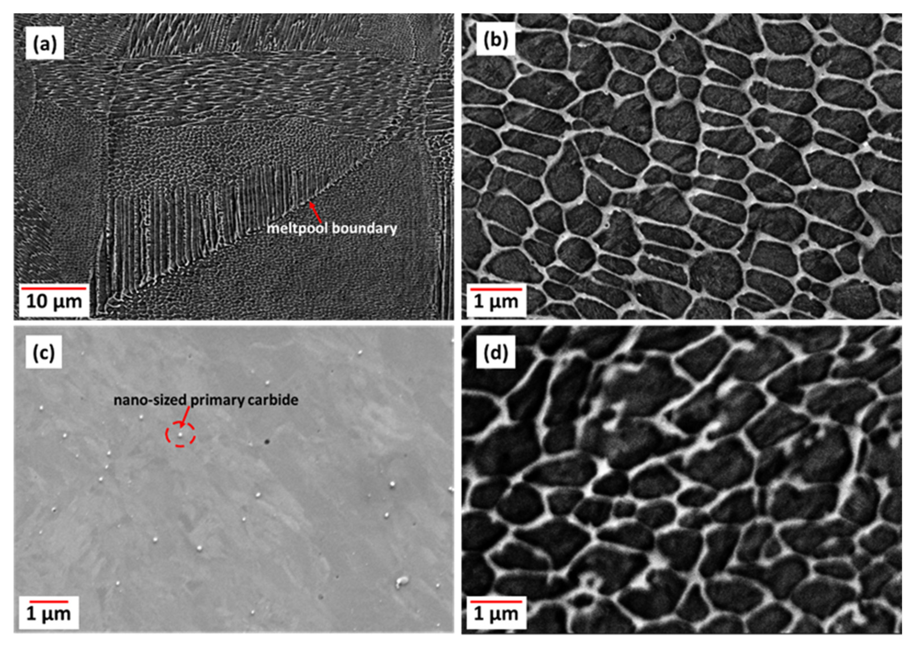
19] that the cell sizes ranged between 0.5 and 1 µm in austenitic steel, which maintained their size, even with post heat treatment of 700 °C. In the preheated condition, as shown in Figure 2c,d, small nano-sized carbides were visible within and on the boundaries of the (sub)-cells. Martensitic laths of the matrix crossed the cell boundaries. The carbide distribution appeared to be denser in the preheated condition. This is probably because the preheat treatment lowered the cooling rate, allowing more time for carbon diffusion, which influenced the distribution of carbon in the austenitic matrix so that carbides could grow. A higher cooling rate means more micro segregations at the cell boundaries.

3.3. Modified 1.2343-Powder

The particles were generally spherical with almost no satellites and a d50 of 30.8 µm (Figure 3). The apparent and tapped density were measured. The mean Hausner ratio was 1.118, a value for good flowability. Since the powder was blended, the size distribution did not show a sharp d50-value like the standard 1.2343-powder.

3.4. Modified 1.2343-As-Built and Preheated LPBF-Test Cuboids

Similarly observed in the standard 1.2343, both the as-built and preheated conditions had these sub-grain cell structures with the presumably lath martensitic matrix and some nanosized carbides. The modified 1.2343 microstructure in both the as-built (Figure 4a,b) and preheated (Figure 4c,d) samples appeared to have thinner cell boundaries than the 1.2343 standard alloy and seemed to soften up the continuous network after preheating.

3.5. Segregations of Standard 1.2343 As-Built and Modified 1.2343

The EDS maps (Figure 5) generated from the 1.2343 as-built samples showed enrichments of Mo, Cr, and V on the cellular boundaries.
Mo, Cr, and V micro segregations on the cell boundaries of AM built HWTS have been reported by other authors [20]. As a result of the rapid solidification of the AM processes, local elemental inhomogeneities do occur, primarily due to differences in the diffusivities of the constituent alloying elements, which tend to segregate at interdendritic areas such as cell boundaries [4]. Compared to the modified alloy and as shown in Figure 6, the standard alloy showed a higher micro segregation of the carbide formers Mo, Cr, and V. It is reasonable to suggest that the somewhat homogenous distribution of the carbide formers as found in the modified 1.2343 in Figure 6 was influenced by the lowered amounts of the composition of these carbide formers compared to the standard composition.

3.6. Phase Characterization of LPBF-Test Cuboids

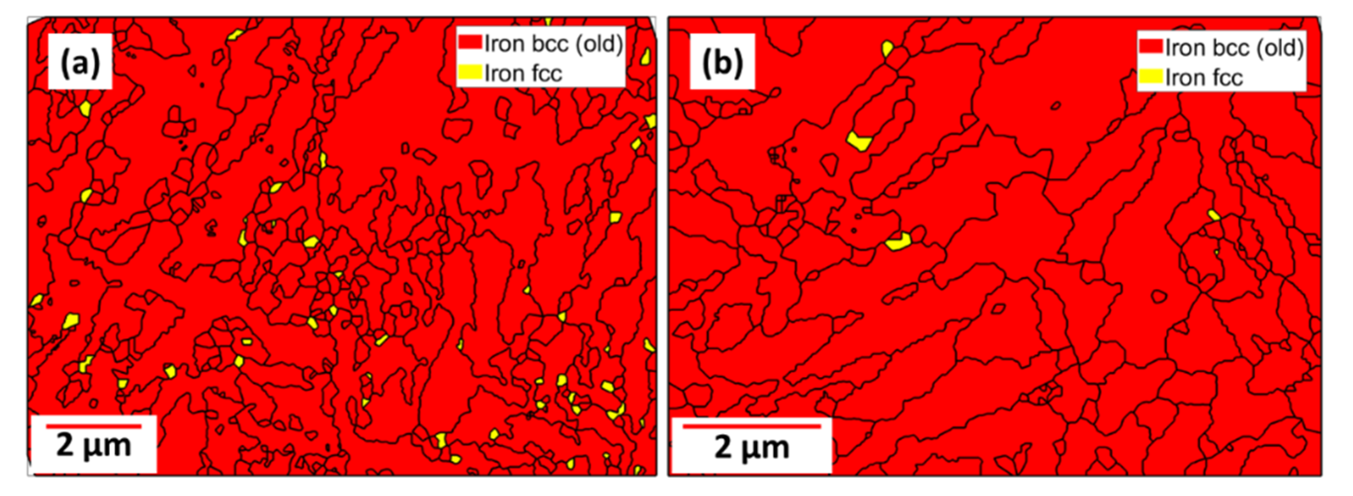
The EBSD maps generated from the standard 1.2343 HWTS are presented in Figure 7 below in the as-built and in the preheated condition (500 °C). In the as-built condition shown in Figure 7a, the microstructure was predominantly martensitic with about an 18% fraction of retained austenite. The predominant martensite fraction seen in the microstructure in Figure 7 is consistent with tool steel microstructure from the LPBF built processes due to the high cooling rates [4] The martensitic transformation takes place when the solidified austenitic cell colonies rapidly cool below the martensite start temperature [17]. During the LPBF processes, as a result of the remelting of the underlying substrate layers typical with the process, some of the martensite may re-transform back into austenite, which upon rapid cooling, again below the martensite start, may not reach the martensite finish temperature and becomes stabilized by diffused carbon from the martensite, leaving a martensitic microstructure with some retained austenite [21].
After the preheating of 500 °C, the retained austenite was significantly reduced from about 18% in the as-built condition (Figure 7a) to about 1.1% (Figure 7b). A similar behavior was observed by the authors [
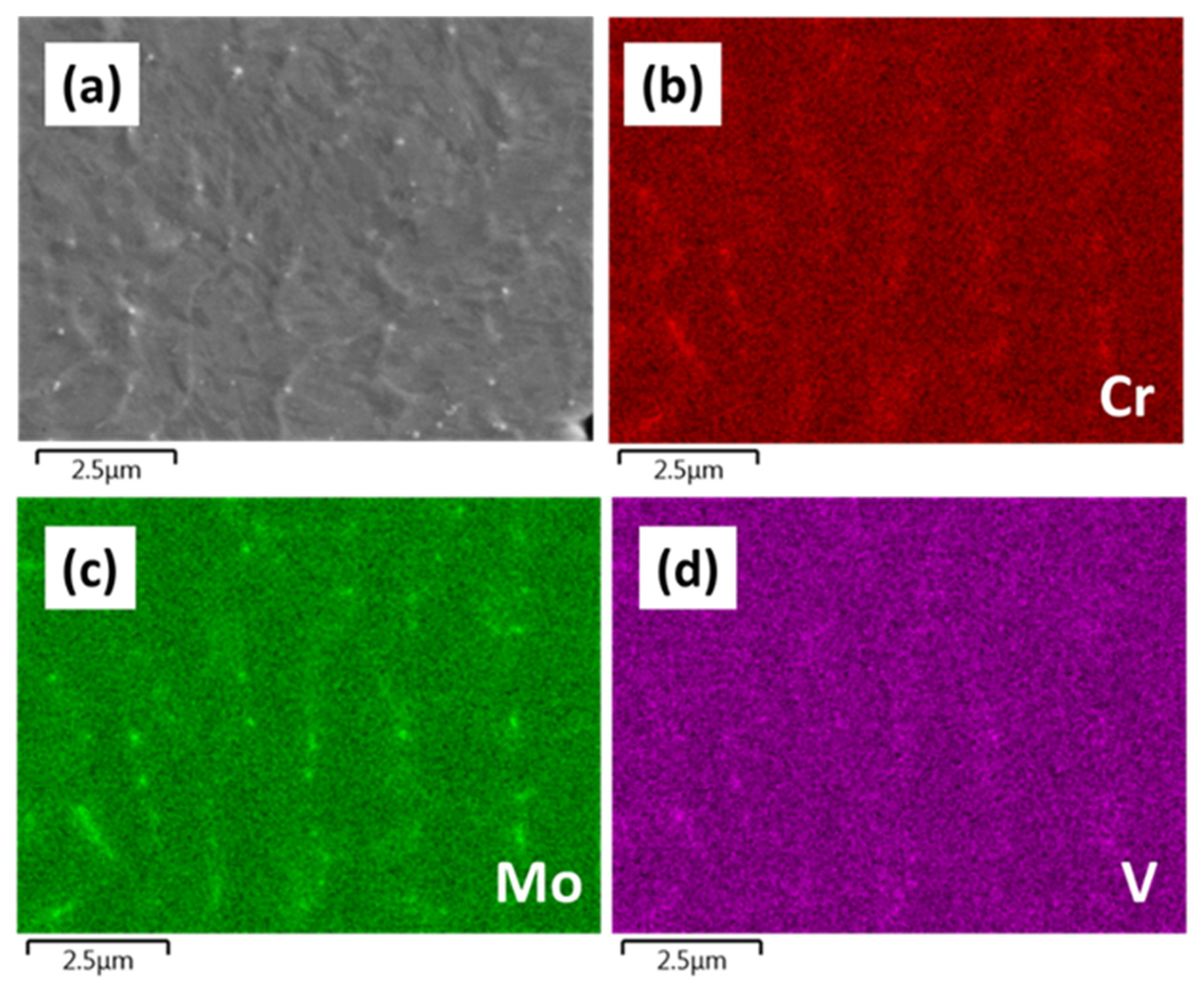
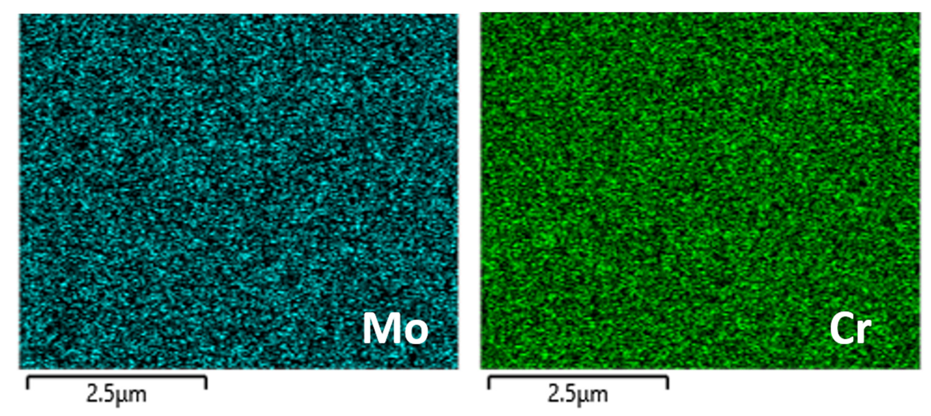
5], who from the LPBF processing of a HWTS using base plate heating, reported a decrease in the amount of retained austenite with an increase in the preheating temperature. The almost complete transformation of austenite into martensite in AM is due to the repeatedly perfect cooling conditions, even in the remelting areas, in combination with the local chemical composition of the austenite. Martensite forms from the austenite in a diffusionless shear transformation under lattice expansion. If the residual strain in the austenitic lattice is too high, it may inhibit this transformation (even if the martensite finish is reachable). Therefore, if martensite formation is possible through the chemical composition combined with the necessary cooling rates in AM, martensite can form if a homogenous distribution of alloying elements is ensured because local differences may stabilize the austenite and lead to RA. The higher the segregation level in the material in certain locations, the steeper the expected gradient of segregating atoms close to these spots, most likely grain or cell boundaries, so that the austenitic lattice is stabilized. In the powder particles, micro segregations were observed at cell boundaries where the most RA was found (Figure 1e,f). In the modified 1.2343, less segregation (Figure 6) went along with a lower amount of RA (Figure 8). Therefore, the amount of RA is dependent on the solubility of the ferrite stabilizers (Cr, Mo, V) in austenite in this steel.
Since a lower amount of RA was found in the preheated condition, it is plausible to suggest that when the high cooling rates in the LPBF process (106–107 K/s) is slowed with appropriate preheating temperatures, the martensite transformation can take place as well as the uniform distribution of alloying elements, aided by better diffusivity to decrease the local residual strain in the austenite.
In the modified 1.2343 as-built condition, as shown in the EBSD map (Figure 8a), the volume fraction of 0.3% retained austenite was measured, which was much lower than the 14–15% reported by [16] and the 4.2% reported by [15]. After tempering at 550 °C for 4 h (Figure 8b), almost no RA was measured. The microstructure of the as-built samples of the modified alloy compared to the standard can be validated to a certain degree with the Scheil simulation (discussed in the next section). It can be observed that the influence of constituent elements such as Mn and Ni, which are known austenite stabilizers and the reduced amount of strong carbide formers (Cr, Mo, V), compared to the standard alloy, which act as ferrite stabilizers, resulted in the modified 1.2343 microstructure.
In the standard 1.2343 alloy, the presence of carbides such as Cr23C6 and a small fraction of M6C were both measured with EBSD in the as-built (Figure 7a) and preheated (Figure 7b) conditions (see supplementary data). Similarly, in the modified 1.2343 alloy, Fe3C, Cr23C6, Mo2C, and Mn7C3 were also measured in the as-built and under tempered conditions using EBSD (also in the supplementary data).
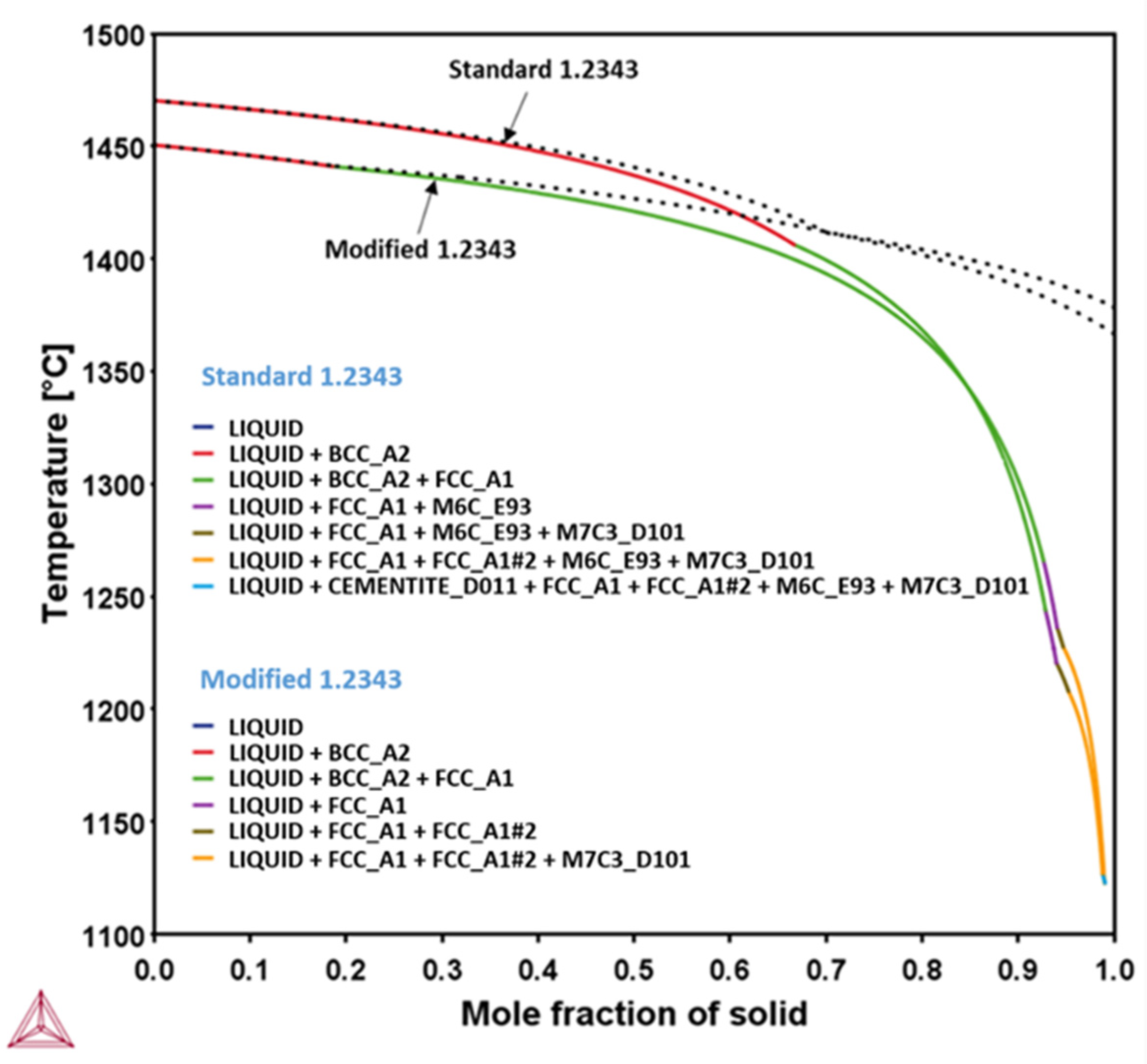
The superimposed TCFE10 based phase simulation of both compositions is shown in Figure 9. At complete solidification, the MC-cementite, M6C, and M7C3 types of carbides are predicted in the standard alloy compared to only M7C3 (Mn7C3) carbides predicted in the modified alloy.
Standard: Formation of δ-ferrite only (1468–1405 °C), γ + δ-ferrite (1405–1265 °C), γ only (1256–1245 °C), M6C, M7C3, MC-cementite
Modified: Formation of δ-ferrite only (1454–1439 °C), γ + δ-ferrite (1439–1271 °C), γ (1271–1228 °C), M6C, M7C3,
It can be seen from the Scheil solidification curves (Figure 9) that the solidification starting temperature was lowered (~1454 °C) in the modified alloy from ~1468 °C in the standard. However, in the modified alloy, the austenite formation started at higher temperatures, which lowers the initial amount of δ-ferrite formed at high temperatures. Compared to the standard alloy, the temperature interval for forming austenite becomes larger (~211 °C vs. ~159 °C), which might allow for a more uniform distribution of the alloying elements in the austenite by way of diffusion. The contribution of the austenite stabilizer Mn and Ni and the ferrite stabilizing elements Cr, Mo, and V on the transformation temperatures is clearly shown in the Scheil simulation. By not cooling close to equilibrium conditions at all, the system has to adjust to the complicated chemical concentration differences. In the absence of the time needed for adjustment, precipitation and other transformations may be suppressed, consequently, the matrix is supersaturated with several alloying elements. It should be noted that not all of the carbide types experimentally measured with EBSD were predicted by the Scheil simulation. A combined approach of using phase simulation, EBSD, and analytical techniques such as transmission electron microscopy (TEM) will be beneficial to accurately characterizing the nano-sized carbides.

3.7. Microhardness Test

The microhardness (HV0.5) results determined from the as-built, preheated as well as one-time tempered (550 °C, 4 h) for both the standard and the modified alloys are presented in Figure 10. These were compared with those at 780 °C for 4 h, which is a classical soft annealing temperature for this alloy under conventional manufacturing. Microhardness values of 607 HV0.5 and 565 HV0.5 were recorded for the as-built modified and standard alloys, respectively. After one-time tempering at 550 °C/4 h, it was observed that there was not a significant drop in the microhardness as the modified alloy’s microhardness marginally dropped to 585 HV0.5 while that of the standard composition increased marginally to 595 HV0.5. For both alloys, after 780 °C post-heat treatment for 4 h, it was observed that the microhardness dropped significantly to 343 HV0.5 and 380 HV0.5. The microhardness of the preheat treated (500 °C) built samples recorded an increase compared to the as-built and as-built at either 550 °C or 780 °C 4 h post heating; 684 HV0.5 and 644 HV0.5 for the standard and modified alloys, respectively. When the preheat treated (500 °C) samples were post-heat treated for 4 h at 550 °C and 780 °C, the modified alloy suffered a drop in microhardness to 560 HV0.5 and 333 HV0.5.
The significant drop in microhardness seen in the 780 °C/4 h post heat treatment can be attributed to the coarsening of carbides such as Mo2C, the Cr23C6 secondary carbides, and the softening of the martensitic matrix. In order to systematically explore the effect of different tempering times on the microhardness properties, a 550 °C tempering temperature was chosen. While for two hours (2 h) and four (4 h), tempering was one time and two times performed, for eight hours (8 h), only one-time tempering was performed. The compared microhardness graph for the various tempering times and steps is presented in Figure 11.
From the graph presented in Figure 11, a number of inferences can be drawn from either the effect of the preheating or tempering steps and time on the microhardness properties.
In general, it can clearly be seen that for both alloys (standard and modified 1.2343) under the preheat treated condition without tempering, the microhardness reached the highest values compared to all of the other conditions (as-built samples or as-built + tempered samples). The preheating temperature of 500 °C could achieve the decomposition of the residual retained austenite and the growth of secondary carbides (Figure 4c) without further tempering steps.
The microhardness of the preheated standard steel decreased with increasing tempering times and stayed (with one exception) above the level of the other steels at different conditions. A decrease in the hardness of the AM microstructure can mostly be attributed to the softening of the martensitic matrix through changes in the cell structure. In addition, coarsening of the carbides can be assumed.
The overall higher hardness of the standard steel compared to the modified steel was attributed to the higher possible amount of carbides because of the higher amount of carbide formers in the alloy composition.
The as-built standard steel showed a lower hardness than the preheated standard steel because of the existence of RA, which softens the material. Since the course of the hardness over the tempering times (e.g., second hardness maximum at two times tempering for 4 h) has to be explained by the development of the microstructure, the kind, size, and distribution of the carbides, cell structures, and the existence of RA need to be investigated. Because the as-built version of the steel could not reach the high hardness values of the preheated steel at the given temperatures (with one exception), it shows that the initial condition of the microstructure before tempering is crucial for the microstructure development over time. The initial microstructure needs to be characterized accurately to be able to follow the evolution through tempering (e.g., it has already been observed, but not quantified yet, that the primary carbides in the preheated as-built condition, due to lower cooling rates during the printing process, were usually bigger and seemed to be more numerous). Other relevant features for defining changes in the microstructural properties are the cell sizes, the structure of the cell network (continuous connection of cell boundaries), the thickness of the cell boundaries, and the occupancy with carbides. Different microstructures influence the diffusion processes, which are controlled by temperature, time, and concentration. Therefore, it is clear that the hardness development of the modified steel is different, and the topics discussed above also apply.
The preheated modified steel showed a steeper decrease in hardness than the standard steel. This shows the exacerbated effect of tempering on the microstructural changes. The tensions are easier to relieve because of the smaller amount of carbides. The increase in hardness after tempering for 8 h shows the influence of tempering time on carbide precipitation.
The hardness differences between the as-built modified steel and the preheated modified steel was smaller than the difference between the as-built and the preheated standard steels.
In the following, detailed comparisons of the hardness values of the standard and the modified steels for different tempering times are discussed.
The modified alloy showed the highest possible hardness without preheating after one-time 2 h tempering, which was lower compared to the highest hardness recorded for the standard alloy without preheating (as-built + two-times, 4 h).
The standard alloy with preheating yielded a higher hardness than the standard alloy as-built samples with the exception of one sample (as-built + 2 times tempered for 4 h).
In the investigation by [15] of a similar alloy, after preheating of about 380 °C, the authors noted that the hardness increased after 550 °C for 2 h of tempering and attributed it to the residual retained austenite decomposition and secondary carbide precipitations.
For the modified as-built samples (without preheating), after tempering at 550 °C for 2 h, a marginal increase in microhardness was observed, but it should be noted that beyond 2 h of tempering, the hardness began deteriorating.
In the as-built standard alloy however, once or twice tempering for 2 h and 4 h still led to higher microhardness but deteriorated at 8 h of tempering. In the study by [16] of as-built samples, the optimal hardness properties were reported after 2 h of tempering at 500 °C. The authors also reported only a marginal increase in the microhardness after double tempering.
For both steels, it can be seen that the biggest impact on the hardness improvement compared to the as-built samples could be achieved by the preheating treatments without tempering steps.

3.8. Tensile Tests

Since the preheated samples had the best hardness results (Figure 10), tensile tests were performed with 500 °C preheating temperature for both alloys without any tempering (Table 3).
These results are comparable with conventionally produced values. With an elongation no higher than 1% in the modified alloy and 0.80% for the standard, investigations are currently ongoing to find the best combination of strength and ductility. The preliminary findings already show a promising increase in strength after tempering for both alloys.

4. Conclusions and Outlook

In this article, the mechanical properties of the LPBF-manufactured HWTS 1.2343 (standard) and a modified alloy version were investigated and compared, both in the as-built and under different heat treatment regimes. A major part of this work was the investigation of the influence of a preheated build plate on minimizing the amount of the retained austenite and the influence of tempering on the ability to maintain the hardness and strength. Austenitisation was avoided in this work as one of the overarching goals was to decrease the number of heat treatment steps and shorten the process chain.
Crack-free samples of both alloys were produced with a relative density of at least 99.8% with and without the heating plate. With preheating and a consequently lowered cooling rate, a decrease in the amount of retained austenite (18% to 1.1%) was observed.
A predominant martensite with ~5% retained austenite was measured in the standard 1.2343 powder particle microstructure, indicating the influence of different cooling rates on the amount of RA. In the modified 1.2343 (as-built), attributed to the chemical composition, nearly no RA was detected, which also accounted for the higher hardness of the modified alloy compared to the standard alloy.
At the preheating of 500 °C, both alloys reached their peak hardness. Further heat treatment caused a decline in hardness. The comparatively higher hardness of the standard 1.2343 to the modified can be presumed to be due to the lower carbide amount in the modified 1.2343. Twice tempering of the preheated samples was not seen to have brought any hardness benefit (industrial benefit).
With the as-built + tempering (550 °C, 4 h) of both alloys, compared to 780° C, 4 h, the 780° C hardness deteriorated to less than 400 HV0.5, which can be attributed to the coarsening of carbides such as Mo2C, the Cr23C6 secondary carbides, and the softening of the martensitic matrix.
The standard 1.2343 showed, in the preheated condition, an ultimate strength (UTS) of 1874 MPa, yield strength (YS) of 1445 MPa, and an elongation (El) of 1.0% when compared to that of the modified with a UTS—1811 MPa, YS—1211 MPa, and El—1.0%.
Further investigations are ongoing to achieve the best possible combination of strength and ductility. To understand how microstructural elements are influenced by heat treatments and the contribution on the mechanical properties, systematic and more detailed analytical microstructural investigations have to be conducted on the nano-sized carbides along with local elemental distribution and cell structures, especially the changes in the cell boundaries through several heat treatments.

Supplementary Materials

The following supporting information can be downloaded at: https://www.mdpi.com/article/10.3390/jmmp6030063/s1.

Author Contributions

Conceptualization, I.R. and F.A.-K.; Data curation, F.A.-K. and S.E.; Investigation, F.A.-K.; Methodology, I.R. and F.A.-K.; Project administration, I.R.; Supervision, I.R., J.H.S. and A.B.-P.; Writing—original draft preparation, I.R. and F.A.-K.; Writing—review and editing, I.R. and F.A.-K. All authors have read and agreed to the published version of the manuscript.

Funding

This work was funded by the Deutsche Forschungsgemeinschaft (DFG, German Research Foundation) under Germany’ s Excellence Strategy–EXC-2023 Internet of Production–390621612.

Data Availability Statement

Not applicable.

Conflicts of Interest

The authors declare no conflict of interest.

References

  1. Ren, B.; Lu, D.; Zhou, R.; Li, Z.; Guan, J. Preparation and Mechanical Properties of Selective Laser Melted H13 Steel. J. Mater. Res. 2019, 34, 1415–1425. [Google Scholar] [CrossRef]
  2. Yan, J.J.; Zheng, D.L.; Li, H.X.; Jia, X.; Sun, J.F.; Li, Y.L.; Qian, M.; Yan, M. Selective Laser Melting of H13: Microstructure and Residual Stress. J. Mater. Sci. 2017, 52, 12476–12485. [Google Scholar] [CrossRef]
  3. Totten, G.E.; Xie, L.; Funatani, K. Handbook of Mechanical Alloy Design; Mechanical Engineering; M. Dekker: New York, NY, USA, 2003; Volume 164. [Google Scholar] [CrossRef]
  4. Bajaj, P.; Hariharan, A.; Kini, A.; Kürnsteiner, P.; Raabe, D.; Jägle, E.A. Steels in Additive Manufacturing: A Review of Their Microstructure and Properties. Mater. Sci. Eng. A 2020, 772, 138633. [Google Scholar] [CrossRef]
  5. Mertens, R.; Vrancken, B.; Holmstock, N.; Kinds, Y.; Kruth, J.P.; Van Humbeeck, J. Influence of Powder Bed Preheating on Microstructure and Mechanical Properties of H13 Tool Steel SLM Parts. Phys. Procedia 2016, 83, 882–890. [Google Scholar] [CrossRef] [Green Version]
  6. Nagahama, T.; Mizoguchi, T.; Yonehara, M.; Kyogoku, H. The Porosity and Mechanical Properties of H13 Tool Steel Processed by High-Speed Selective Laser Melting. In Proceedings of the 2019 International Solid Freeform Fabrication Symposium, Austin, TX, USA, 12–14 August 2019; pp. 677–683. [Google Scholar]
  7. Wang, J.; Liu, S.; Fang, Y.; He, Z. A Short Review on Selective Laser Melting of H13 Steel. Int. J. Adv. Manuf. Technol. 2020, 108, 2453–2466. [Google Scholar] [CrossRef]
  8. Kunz, J.; Herzog, S.; Kaletsch, A.; Broeckmann, C. Influence of Initial Defect Density on Mechanical Properties of AISI H13 Hot-Work Tool Steel Produced by Laser Powder Bed Fusion and Hot Isostatic Pressing. Powder Metall. 2022, 65, 1–12. [Google Scholar] [CrossRef]
  9. Köhler, M.L.; Ali, F.; Herzog, S.; Suwanpinij, P.; Kaletsch, A.; Broeckmann, C. Influence of Cr3C2 Additions to AISI H13 Tool Steel in the LPBF Process. Steel Res. Int. 2022, 93, 2100454. [Google Scholar] [CrossRef]
  10. Bohlen, A.; Freiße, H.; Hunkel, M.; Vollertsen, F. Additive Manufacturing of Tool Steel by Laser Metal Deposition. Procedia CIRP 2018, 74, 192–195. [Google Scholar] [CrossRef]
  11. Bailey, N.S.; Katinas, C.; Shin, Y.C. Laser Direct Deposition of AISI H13 Tool Steel Powder with Numerical Modeling of Solid Phase Transformation, Hardness, and Residual Stresses. J. Mater. Processing Technol. 2017, 247, 223–233. [Google Scholar] [CrossRef]
  12. Xue, L.; Chen, J.; Wang, S.H. Freeform Laser Consolidated H13 and CPM 9V Tool Steels. Metallogr. Microstruct. Anal. 2013, 2, 67–78. [Google Scholar] [CrossRef] [Green Version]
  13. Haghdadi, N.; Laleh, M.; Moyle, M.; Primig, S. Additive Manufacturing of Steels: A Review of Achievements and Challenges. J. Mater. Sci. 2021, 56, 64–107. [Google Scholar] [CrossRef]
  14. Armillotta, A.; Baraggi, R.; Fasoli, S. SLM Tooling for Die Casting with Conformal Cooling Channels. Int. J. Adv. Manuf. Technol. 2014, 71, 573–583. [Google Scholar] [CrossRef] [Green Version]
  15. Huber, F.; Bischof, C.; Hentschel, O.; Heberle, J.; Zettl, J.; Nagulin, K.Y.; Schmidt, M. Laser Beam Melting and Heat-Treatment of 1.2343 (AISI H11) Tool Steel—Microstructure and Mechanical Properties. Mater. Sci. Eng. A 2019, 742, 109–115. [Google Scholar] [CrossRef]
  16. Casati, R.; Coduri, M.; Lecis, N.; Andrianopoli, C.; Vedani, M. Microstructure and Mechanical Behavior of Hot-Work Tool Steels Processed by Selective Laser Melting. Mater. Charact. 2018, 137, 50–57. [Google Scholar] [CrossRef]
  17. Åsberg, M.; Fredriksson, G.; Hatami, S.; Fredriksson, W.; Krakhmalev, P. Influence of Post Treatment on Microstructure, Porosity and Mechanical Properties of Additive Manufactured H13 Tool Steel. Mater. Sci. Eng. A 2019, 742, 584–589. [Google Scholar] [CrossRef]
  18. Krell, J.; Röttger, A.; Geenen, K.; Theisen, W. General Investigations on Processing Tool Steel X40CrMoV5-1 with Selective Laser Melting. J. Mater. Processing Technol. 2018, 255, 679–688. [Google Scholar] [CrossRef]
  19. Saeidi, K. Stainless Steels Fabricated by Laser Melting. Ph.D. Thesis, Department of Materials and Environmental Chemistry, Arrhenius Laboratory, Stockholm University, Stockholm, Sweden, 2016. [Google Scholar]
  20. Brooks, J.; Robino, C.; Headley, T.; Goods, S.; Griffith, M. Microstructure and Property Optimization of LENS Deposited. 1999 Int. Solid Free. Fabr. Symp. 1999, 13, 375–382. [Google Scholar]
  21. Holzweissig, M.J.; Taube, A.; Brenne, F. Melting, Microstructural Characterization and Mechanical Performance of Hot Work Tool Steel Processed by Selective Laser. Met. Mater Trans B 2015, 46, 545–549. [Google Scholar] [CrossRef]
Figure 1. (a) The SEM-morphology of the standard 1.2343 steel powder particles. (b) Particle size distribution (PSD). (c) Particle cross-section with cellular microstructure. (d) EBSD image of the martensite and retained austenite (RA). (e,f) EDS images showing the V- and Mo-micro segregations on the cell boundaries.
Jmmp 06 00063 g001
Figure 2. Standard 1.2343 SEM micrograph: (a) the as-built 30 µm layer thickness and (b) 60 µm layer thickness of 1.2343. Preheated at 500 °C SEM micrograph: (c) 30 µm layer thickness and (d) 60 µm layer thickness.
Jmmp 06 00063 g002
Figure 3. The modified 1.2343. (a) SEM morphology of the particles. (b) Histogram and cumulative distribution of the particle size, d50–30.8 µm.
Jmmp 06 00063 g003
Figure 4. The SEM micrographs of the modified 1.2343 as-built 30 µm layer thickness and (a) cell structure in different orientations. (b) Cell structure at higher magnification. Preheated at 500 °C (c) with primary carbides. (d) Cell structure at higher magnification.
Jmmp 06 00063 g004
Figure 5. The standard 1.2343 as-built (a) showing the cell boundaries with carbides. (bd) EDS map showing the micro segregations of Mo, Cr, and V on the cell boundaries and carbides. The presence of the concentration gradients of the micro segregation is best seen in Figure 5c (Mo).
Jmmp 06 00063 g005
Figure 6. The modified 1.2343 as-built EDS map showing no protruding Mo and Cr on the cell boundaries compared to the standard 1.2343.
Jmmp 06 00063 g006
Figure 7. The standard 1.2343 as-built: (a) Retained austenite (Ra)—18%. Preheated treatment (500 °C). (b) Preheated treatment (500 °C): Retained austenite (Ra)—1.1%. Faster cooling rates in the LPBF process will lead to a higher amount of RA in the built parts.
Jmmp 06 00063 g007
Figure 8. The modified 1.2343 as-built: (a) Martensite, retained austenite (Ra)~0.3%. (b) The modified 1.2343 as-built: tempered at 550 °C for 4 h, Ra~0%.
Jmmp 06 00063 g008
Figure 9. The superimposed Scheil simulation (TCFE10) of both the modified and standard 1.2343.
Jmmp 06 00063 g009
Figure 10. The microhardness graph of the standard and modified 1.2343: the as-built, as-built + 550 °C or 780 °C/4 h post heated, preheat treated, preheat treated (500 °C) + 550 °C or 780 °C/4 h post heated.
Jmmp 06 00063 g010
Figure 11. The microhardness graph of the modified and standard 1.2343: as-built, preheated (500 °C), tempered (TP) at 550 °C one time (1×) or two times (2×) for 2 h, 4 h, and 8 h.
Jmmp 06 00063 g011
Table 1. The alloy composition (wt.%).
HWTSCSiCrMoMnVNiFe
Standard 1.23430.412.076.141.49<0.010.46-Bal.
Modified 1.23430.382.065.611.191.110.413.07Bal.
Table 2. The process parameter design.
As-Built/Pre-Heating (500 °C)
AlloyLaser Power (W)Scan Speed (mm/s)Hatch Distance (µm)Layer Thickness (µm)
Standard 1.23432007508030, 60
Modified 1.2343200550-95070, 80, 9030
Table 3. The results of the tensile test (standard 1.2343 and modified 1.2343).
HWTSRm* (MPa)RP0.2* (MPa)
Preheated 1.2343 (Standard)18741445
Preheated (Modified)18111211
Rm*—ultimate tensile strength. RP0.2*—yield strength.
Publisher’s Note: MDPI stays neutral with regard to jurisdictional claims in published maps and institutional affiliations.

