1. Introduction
Magnetic abrasive finishing (MAF) is characterized by a high complexity of the process, powder motion kinematic, mechanical and magnetic interaction of forces and numerous influencing factors. To these factors belong process kinematics (finishing of flat or freeform surface, wave or tube, etc.), process parameters (cutting speed, feed rate, working gap and magnetic flux density), workpiece properties (mechanical and magnetic properties, initial surface), MAF tool (quantity, dimension, arrangement of permanent- or electromagnets), magnetic abrasive powder (type, manufacturing method, grain size, ferromagnetic and abrasive percentage) and cooling lubricant (type, chemical reactions).
Various studies investigate the process parameters [
1,
2,
3,
4,
5,
6,
7] and describe for example the influence of the working gap, the abrasive weight percentage and rotational speed on the normal finishing force and torque, while MAF of the paramagnetic disk workpiece that was clamped between two MAF tools [
1]. Further work describes the influence of abrasive grain size as well as feed rate in addition to abovementioned process parameters on the percentage change in surface roughness Ra, during the equal MAF process of paramagnetic stainless steel and copper alloy [
2]. The working gap has the highest influence on the surface roughness improvement and normal finishing force by MAF [
1,
2]. The voltage supplied to the electromagnet also has a significant impact on the surface roughness improvement as well as on the normal and tangential cutting force, while MAF of SS316L with a single electromagnet [
3,
4]. Further work indicates that process parameters such as voltage supplied to the electromagnet and working gap have a major influence on the material removal [
5]. The process parameters of ultrasonic assisted magnetic abrasive finishing were also investigated, while finishing hardened AISI 52,100 steel and improved the surface roughness Ra up to 22 nm within 80 s [
6]. Simulation of the magnetic flux density distribution on a paramagnetic workpiece between the MAF tool and optional permanent magnet below the workpiece show that an additional NdFeB magnet improves by an increase of 1.5 times the magnetic flux density in the working gap [
7].
In many studies, the process parameters were investigated on a multi-factor basis [
1,
2,
3,
4,
5,
7,
8]. Three or five values were selected for each process parameter. By using, for example, standard statistical analysis such as, a signal to noise ratio and analysis of variance (ANOVA), the number of required tests could be reduced significantly. A variety of different process parameters could be tested and process models were developed. However, certain effects could not be taken into account by multi-factor tests that take place in such complex processes as the magnetic abrasive finishing. Therefore, the one-factor tests were used in this work in order to separate the complex relationships and to determine effects more precisely. Thus, the effect of the mechanical powder compaction in the optimal working gap was discovered, which leads to a significant increase in the process capability for magnetic abrasive finishing of flat surfaces of ferromagnetic workpieces.
Magnetic abrasive finishing is used in different kinematic variations for machining flat surfaces [
1,
2,
3,
4,
5,
6,
7,
8,
9,
10,
11], shafts [
12,
13,
14], thin-walled tubes [
15,
16,
17,
18,
19], wires [
20,
21], cutting tools [
22,
23,
24] and freeform surfaces [
25,
26,
27]. However, this usually requires separate equipment, which increases the time and costs involved. MAF shows a high potential for use on CNC machine tools as a standard tool to polish workpieces directly after the milling process. However, a high processing time (up to 5 h) is often required in order to achieve a high surface finish (e.g., Rz up to 0.13 µm), especially on rough initial surfaces (Rz up to 100 µm) after additive manufacturing [
28]. In the present paper, a novel top cover structure of the MAF tool is presented, which in combination with an optimal working gap, ensures the effect of mechanical powder compaction. This increases the productivity (feed rate of up to 25 mm/min in one process step) and achieves a very high surface quality (surface roughness Ra up to 0.02 µm, Rz up to 0.12 µm). Moreover, the process parameters and the influence of different initial surfaces after face milling, end milling, ball end milling and grinding are investigated in detail.
2. Materials and Methods
The investigations on magnetic abrasive finishing are carried out on a 5-axis CNC machine tool from DMG MORI AG (Bielefeld, Germany) of type DMU Ultrasonic 125 P. The spindle is equipped with a standard HSK 63A interface for the tool holder in order to obtain enough power (85 kW), torque (40 Nm) and speed (up to 30,000 rpm) to process the workpiece with a large milling head as well as small ball end mill.
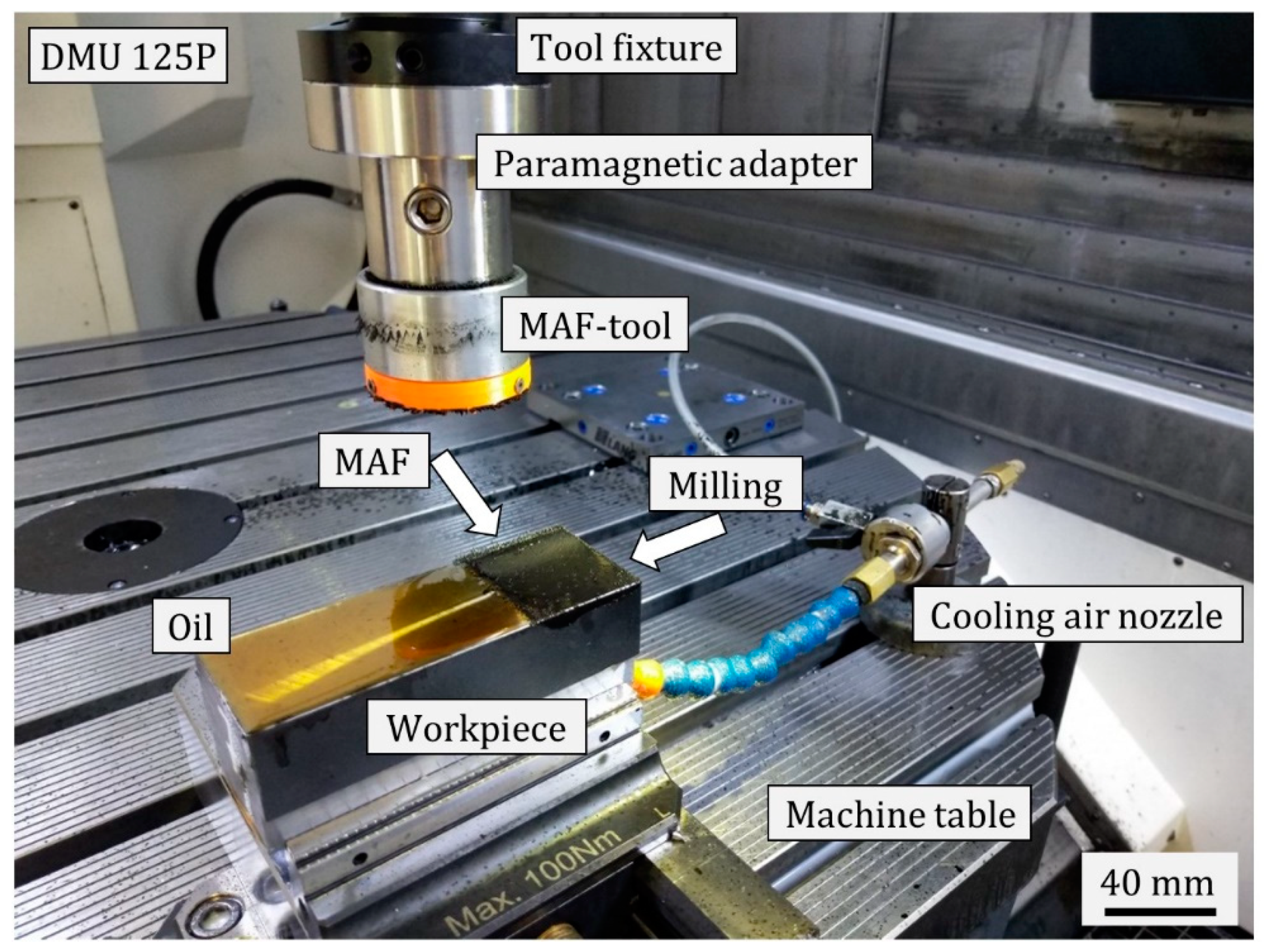
Figure 1 shows the experimental setup for magnetic abrasive finishing on a CNC machine tool. The test samples were clamped in a vice, milled in the longitudinal direction with a milling head, then oiled and processed with the MAF tool in the transverse direction. The microchips, magnetic abrasive particles and oil formed a slurry during the process that was manually removed. The cooling air nozzle was used on the workpiece side during the tests so that the air cools the sample from below in order to reduce the propagation of heat. Three passes were made on a sample with the MAF tool. A ferromagnetic construction steel 1.0037 was used as the test material. The stationary metal analyzer from SPECTRO Analytical Instruments GmbH (Kleve, Germany) type SPECTROMAXx was used for the precise measurement of the chemical composition of the workpiece. The universal hardness testing machine, KB 250 from KB Prüftechnik GmbH (Hochdorf-Assenheim, Germany), was used to determine the Vickers hardness HV10. The results are summarized in
Table 1.
The tool system for magnetic abrasive finishing on the machine tool consists of the tool fixture, the paramagnetic adapter, the MAF tool body, the Fe14Nd2B permanent magnet and the specially designed top cover structure. This structure maintains the mechanical compression of the magnetic abrasive powder inside the working gap that significantly increases the process capability. The magnet is unrestrained and held back by the top cover.
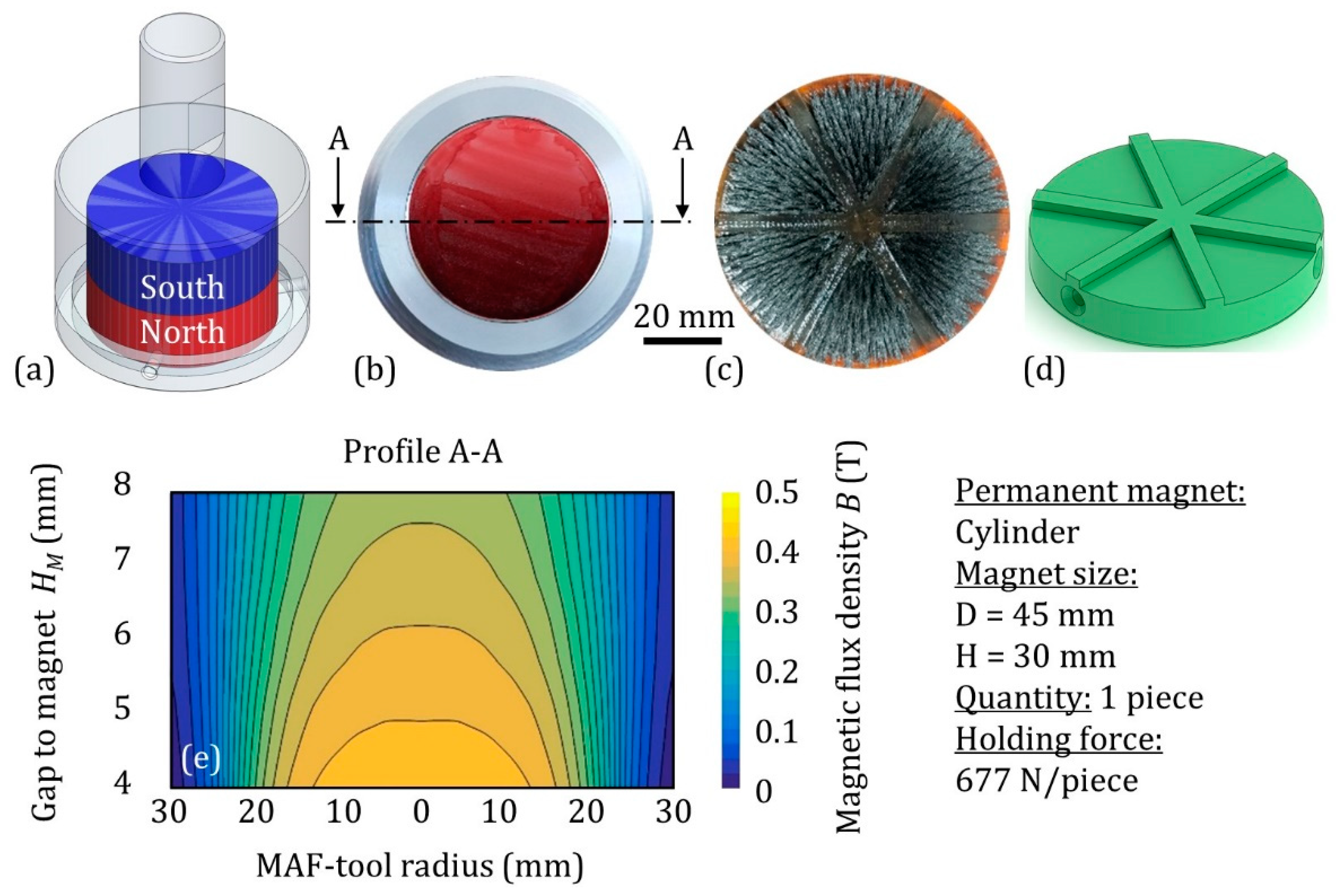
Figure 2 shows the MAF tool that is equipped with a relatively large and strong cylindrical permanent magnet (Ø 45 mm × 30 mm), which ensures a high magnetic flux density (above 0.4 T on the 4 mm gap to the magnet) over a wide area (
Figure 2e). The surface on the real prototype was marked in colour corresponding to the north pole side with the marker (
Figure 2b). To measure the distribution of the magnetic flux density in the working gap, a teslameter from Wuntronic GmbH (München, Germany) type Koshawa 5 was used and fixed in the vice. The MAF tool was clamped in the machine spindle and moved radially to the teslameter along the whole MAF tool diameter at certain fixed distances. Measuring points were recorded every 0.5 mm along a measuring section. In total, five measuring sections were recorded on the gap to the magnet from 4 to 8 mm with a step of 1 mm in the axial direction. Further, the measuring points were interpolated into a field diagram for better illustration (
Figure 2e).
The tactile mobile roughness measuring instrument from Hoffmann Group (München, Germany) type Perthometer H1 was mainly used for surface inspection. The mobile roughness device enables the measurement near the machine tool, increases the flexibility and reduces the measuring effort. The surface roughness parameter Ra was used as the main criterion for surface quality, as on the one hand, the surface character of the manufacturing process is known and on the other hand, the Ra parameter is characterized by low scatter and weak response to the disturbances and provides robust, repeatable measurement results. Each experimental pass was measured 6 times corresponding with milling direction (
Figure 1). Each experimental process parameter was repeated 3 times and summarized in 18 measurements for 1 point on the graphic chart.
The tactile stationary roughness measuring instrument from Taylor Hobson (AMETEK GmbH, Weiterstadt, Germany) type Form Talysurf PGI 1500E was used for the measurement of numerous roughness parameters of the different initial surface types as well as surfaces generated by MAF. The measurements are carried out in the laboratory at a constant temperature. An optical microscope from Alicona Imaging GmbH (Graz, Austria) type Infinite Focus was used to evaluate the surface topography after milling with different tools as well as magnetic abrasive finishing. The images of the surface structure and the 3D measurement of the surface topography before and after the MAF were compared.
In this test, the following process parameters were varied: feed rate, spindle speed corresponding with cutting speed, working gap including different grain sizes and gap to the magnet. In addition, the influence of the initial surface after face milling, end milling, ball end milling and grinding on the magnetic abrasive finishing was investigated. All tests were carried out on a one-factor basis in order to better separate the complex relationships and more accurately identify effects.
The process parameters for the investigations are shown in
Table 2. Condition A was used for the variation of the feed rate; Condition B for the spindle speed corresponding with cutting speed; Condition C for the working gap; and Condition D for the gap to the magnet as well as the output surface. The cooling air nozzle was used only in Condition D in order to avoid excessive heat development in the process with long machining times and overheating of the permanent magnet, since the magnet loses the magnetic flux density as the temperature increases. The designation 20 × 2 means that the feed rate of 20 mm/min was used in the bidirectional magnetic abrasive finishing process that means a back-and-forth movement. The workpiece width was 50 mm and the traverse distance of the MAF tool was 90 mm, so that the MAF tool passed completely over the workpiece.
The magnetic abrasive powder FerroMAP with a grain size of 200 to 315 µm (200/315 µm) was used in all tests. In the detailed tests of the working gap, two additional grain sizes of 315/400 µm and 400/630 µm were used. FerroMAP consists of Fe as the base material including abrasives such as TiC, SiC and Al2O3.
3. Results and Discussion
3.1. Feed Rate
The most important process parameters for magnetic abrasive finishing on the machine tools are the working gap, the cutting speed and feed rate as well as the magnetic flux density in the working gap. Initially, the feed rate was investigated, as this parameter defines the productivity corresponding to processing time and significantly influences the time required for further tests. The initial surface was created for
Section 3.1,
Section 3.2,
Section 3.3 and
Section 3.4 by face milling. The process parameters are shown in
Table 3 under FM. The initial roughness Ra was 0.17 µm with a standard deviation of 0.02 µm. When using the conventional top cover structure (flat, without structure), the surface quality for used process kinematic, ferromagnetic workpiece material and MAF tool was not improved. By using a top cover structure (
Figure 2d), the surface quality could be significantly improved. The top cover structure leads to a local reduction of the working gap where the magnetic abrasive powder has to flow through a smaller cross section. This leads to the effect of mechanical powder compaction in the working gap, which increases significantly the process intensity.
Figure 3 shows the influence of the feed rate on the surface roughness Ra and confirms the general rule in abrasive precision machining that higher machining time corresponds to lower feed rate and leads to better surface quality. This relationship is explained by the fact that a lower feed rate leads to an increase of the quantity of the active grains in the process and the frequency of material removal, so that the initial milled profile is converted more intensively into a new roughness profile.
At a feed rate of f = 25 mm/min, the milled initial roughness value decreased from Ra = 0.166 µm to Ra < 0.06 µm. A further reduction of the feed rate led to a more isotropic surface and an exponential reduction of surface roughness. At a feed rate of f = 10 mm/min, the surface roughness was reduced to Ra = 0.04 µm and was close to the machining limit for the used grain size, process parameters and steel grade. For a further series of tests, the feed rate of f = 25 mm/min was used, as the surface quality is significantly improved while productivity is relatively high.
3.2. Spindle/Cutting Speed
In most cases, a higher cutting speed improves the surface quality during mechanical processing up to a certain limit. With increased cutting speed, the removal rate is also increased, but if certain values are exceeded, this leads to deeper grain penetration and correspondingly increased roughness of the surface. In the case of abrasive precision and polishing processes, the cutting speed is always kept at low values compared to classic grinding processes and is limited to a few m/s regarding the heat development, high cutting depth of the single grains and surface damage. For magnetic abrasive finishing, the optimum cutting speed is in the range from 1 to 5 m/s (which corresponds to 60 to 300 m/min). In the present work, the spindle speed was investigated as a setting parameter. The equivalent or maximum cutting speed was converted for the diameter of the permanent magnet (45 mm).
Figure 4 shows the influence of the spindle speed corresponding to the equivalent cutting speed on the surface roughness Ra. The results show the reduction in surface roughness with increasing cutting speed up to
vc = 130 m/min or approximately2 m/s.
The following reasons are given for these results:
The increase in the cutting speed leads to higher tangential force which acts on single magnetic abrasive particles; the impact energy with which the grains affect the surface; and the depth of cut of single grains.
Increasing the spindle speed at the same feed rate leads to more frequent contact of the powder with the workpiece surface within the same processing time.
The effect of the powder rotation in the working gap is intensified, which leads to the use of new, sharp cutting edges in the process and maintains the self-sharpening effect.
In general, all these effects lead to higher material removal rate, which plays an essential role in removing the initial roughness, the defect layer and surface damage. At the cutting speed vc > 130 m/min an unfavorable heat development was determined, which is developed by the machining process and the friction between the magnetic abrasive powder, the workpiece and the top cover structure that leads to a reduction in the magnetic flux density of the permanent magnet.
3.3. Working Gap
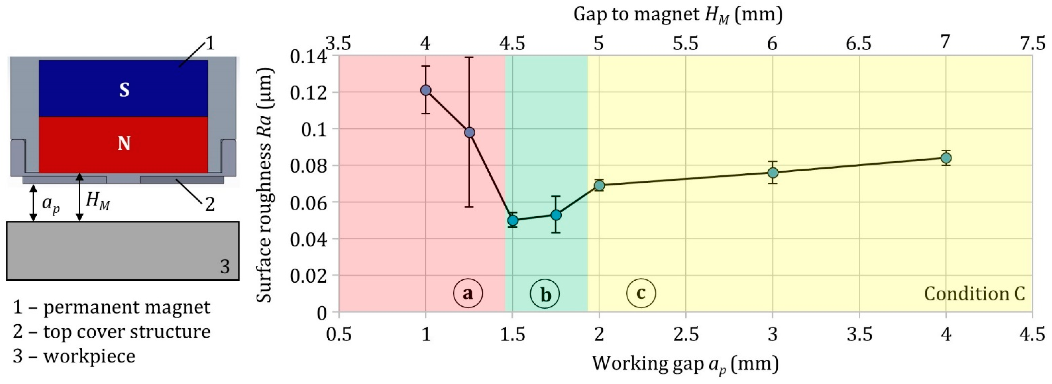
The term working gap is generally unique for abrasive machining and is only used for magnetic abrasive and magnetorheological finishing. In the present paper, the working gap is defined as the gap between the workpiece and the structure of the top cover. To determine the gap to the magnet, the height of the top cover structure (2 mm) and the wall thickness (1 mm) are added to the working gap. The gap to the magnet plays an important role for the intensity of the magnetic flux density in the process and, accordingly, for the normal force of the magnetic abrasive grains. The novel top cover structure, in combination with the optimized working gap, plays a crucial role in the high process capability and ensures the effect of mechanical powder compaction.
Figure 5 shows the influence of the working gap on the surface roughness Ra. The small difference in the working gap significantly affects the magnetic abrasive finishing process and is characterized by the narrow optimal range for the corresponding grain size in which intensive processing takes place. Based on results of investigations the working gap is divided into three process areas: surface damage (area a), optimal area (area b) and low process capability (area c).
Up to a working gap of 2 mm, low process capability was identified for the grain size 200/315 µm. The normal force and process capability slowly increased by decreasing the gap to the magnet, which led to a higher magnetic flux density in the working gap. However, the processing takes place in a suboptimal condition. In the working gap of 1.5 to 2 mm, the mechanical powder compaction is significantly increased so that the process is intensified by a higher cutting force and the surface roughness is reduced to approximately Ra = 0.05 µm. A lower working gap (<1.5 mm) leads to deep grain penetration into the workpiece surface, which produces numerous deep scratches. The surface quality decreases drastically while the surface damage, in the form of deep grooves, increases.
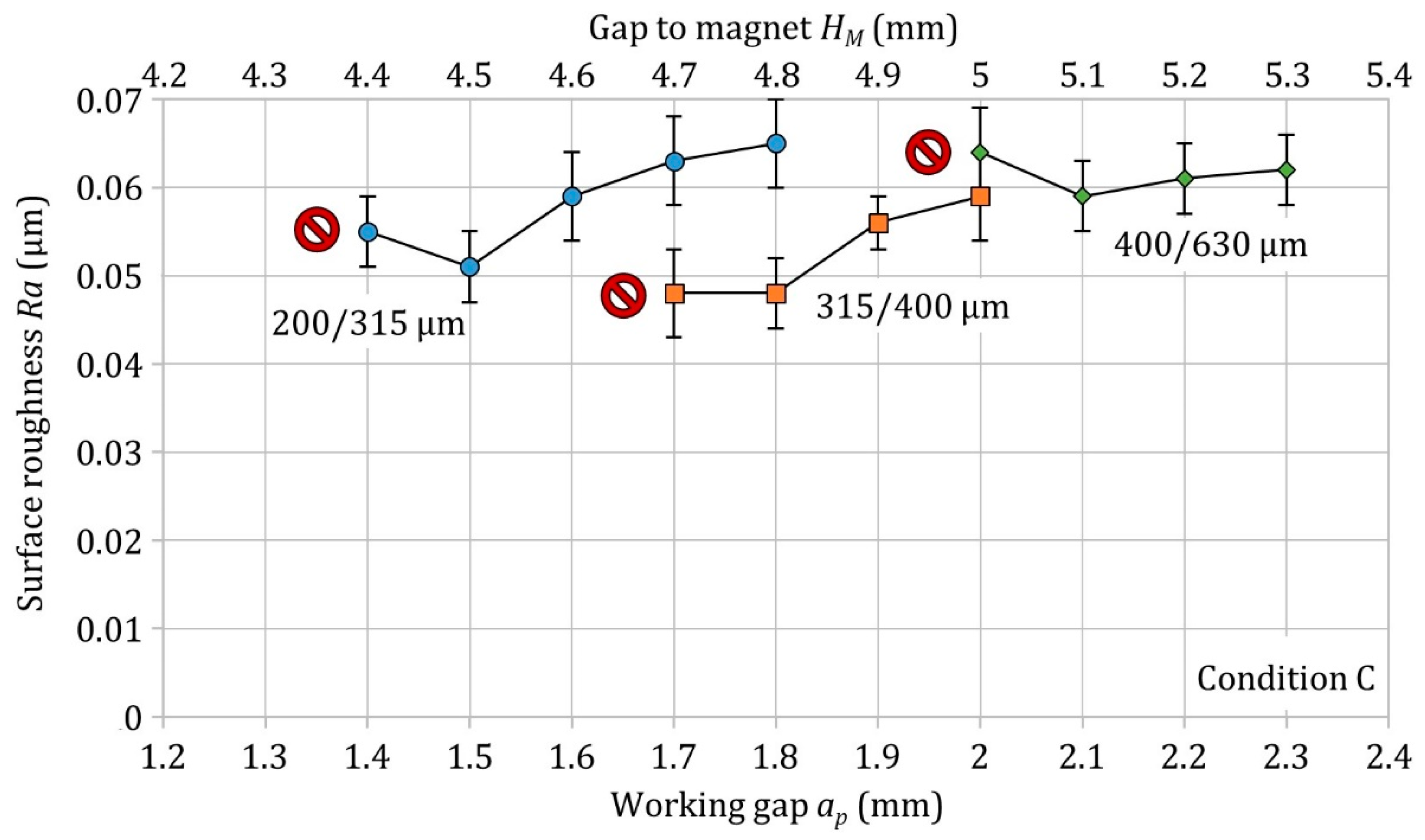
Figure 6 shows the influence of the working gap in the optimal area for 3 grain sizes on the surface roughness Ra. The working gap was varied in 0.1 mm steps until the first deep scratches appeared on the surface. These points have been marked with a red symbol on the graphic.
The results clearly show that each grain size exhibits a limit of the achieved surface roughness. The optimal working gap is higher with a larger fraction of the magnetic abrasive powder. This relationship explains that the optimal mechanical powder compaction is guaranteed with a certain number of grains in the working gap. Larger grains take up more space in the working gap and exhibit the lower packaging level, so the working gap should be increased. If the empirical optimal working gap for magnetic abrasive finishing of plane surfaces by using the top cover structures is divided by the corresponding average grain size, then the result is a factor of 4 to 6. Thus, the optimal working gap is 4 to 6 average grain sizes of the respective powder fraction.
The highest surface quality wasn´t achieved by the smallest grain size of 200/315 µm, but by the grain size of 315/400 µm. In general, a larger grain size leads to a higher volume of the ferromagnetic base material and thus to an increase in the magnetic forces as well as the cutting force that acts on single grains, which leads to deeper grain penetration and higher material removal. However, this also reduces the active number of grains corresponding to the cutting edges that are involved in the abrasive process, which can lead to more inhomogeneous material removal. Therefore, a compromise has to be found for the given task.
3.4. Gap to the Magnet
Figure 7 shows the influence of the gap to the magnet on the surface roughness Ra. The top cover structures of the MAF tool with a height of 1.5 mm to 3 mm were used in 0.5 mm steps. The working gap was always kept constant during the tests, so that the mechanical powder compression was stable. Accordingly, the gap to the magnet increases with the height of the top cover structure, which leads to a reduction in the magnetic flux density and the material removal rate in the process. The magnetic flux density of the strong and large permanent magnet decreases relatively slightly with an increasing distance from the magnet and corresponds to approximately 20 mT/mm from the measurement results with the axial hall sensor of the teslameter (
Figure 2e). However, this reduction becomes noticeable in the achieved surface roughness, as shown by the results of the tests.
A linear increase in the surface roughness corresponds to an approximately linear reduction in the magnetic flux density in the working gap with an increasing distance to the magnet corresponding with the height of the top cover structure. However, the difference in the achieved surface roughness is not significant, as the difference in the gap to the magnet is, e.g., 1 mm. However, the same difference in the working gap by 1 mm shows a significant influence on the process and can indicate a jump into other process area e.g. from area c to area a in
Figure 5.
The deviation in the working gap affects the magnetic abrasive finishing more than the same difference in the gap to the magnet, which reinforces the crucial role of the mechanical powder compaction for an intensive MAF process.
3.5. Initial Surface after Face Milling, End Milling, Ball End Milling and Grinding
The resulting surface of the milling process defines the processing time required to produce the final surface quality and to ensure the requirements for surface topography and integrity. The MAF, as with all finishing processes, requires a certain initial surface quality. A finer initial surface reduces the manufacturing time of the finishing process and, accordingly, the manufacturing effort.
To determine the influence of the initial surface on the final surface after magnetic abrasive finishing, the samples were prepared with different manufacturing technologies and tools, each with two process parameter variations (
Table 3). The second process parameter variation is given in brackets. If no brackets were used, then the process parameter one and two are the same, e.g., for EM-A
1, the following process parameters were used:
n = 1300 min
−1,
vc = 50 m/min,
f = 220 mm/min and
ap = 0.1 mm, while for EM-A
2:
n = 3900 min
−1,
vc = 150 m/min,
f = 660 mm/min and
ap = 0.1 mm were used. The machining was carried out by end mill at axial (EM-A) and tangential (EM-T) directions; face mill (FM) and ball end mill (BM) at vertical and inclined tool axis orientation and by grinding (G) including coarse and fine dressing of the grinding wheel on a separate grinding machine. Then the samples were finished by the MAF tool using constant process parameters. For all manufacturing technologies, the cooling lubricant Novamet 900 at a ratio of 8% was used.
Figure 8 shows the influence of the initial surface on the finished surface roughness Ra. The achieved values before and after the magnetic abrasive finishing are shown in a table below.
The produced initial surfaces are characterized by a wide variation of the surface roughness Ra from 0.035 µm after grinding to 1.21 µm after ball end milling at vertical tool axis orientation. However, a significant roughness reduction was achieved in most of the samples after magnetic abrasive finishing. In general, the roughness of the milled surfaces, according to MAF, was reduced from 70% to 95% and a value of approximately Ra = 0.05 µm was achieved. Machining with end mills usually produces numerous deep grooves, which was particularly pronounced with EM-A2 and EM-T1. These grooves were not completely eliminated by the MAF processing, which is the reason for higher surface roughness. A two-stage MAF process using coarse and fine grains is proposed for surface treatment with deep grooves.
The grinded surface using a coarse dressed grinding wheel was improved from Ra = 0.072 µm to Ra = 0.042 µm after magnetic abrasive finishing. The surface roughness after grinding using a fine dressed grinding wheel showed a roughness of Ra = 0.035 µm and could not be improved after the MAF-process. However, a new surface topography was produced. The matt grinded surface was converted into a polished glossy surface after MAF. The magnetic abrasive finishing of grinded surfaces indicates the limit of the achieved surface quality by MAF with the combination of powder type, grain size, process parameters, tool type, top cover structure and the material being processed as well as the measuring accuracy.
3.6. Surface Roughness Parameters
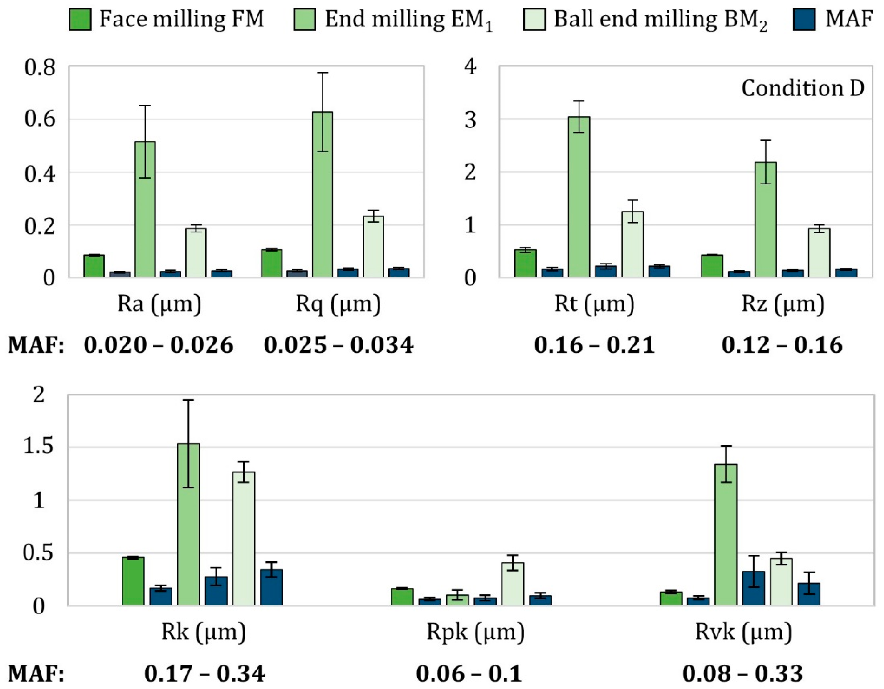
Further measurement of diverse roughness parameters was carried out in the laboratory under a constant temperature using a high-precision stationary tactile roughness measuring device. The results are presented in
Figure 9 and show a significantly lower arithmetic mean deviation Ra than after the measurement with the mobile tactile roughness measuring instrument, as the laboratory measuring device works precisely and under constant temperature conditions. The surface roughness Ra was reduced from approximately Ra = 0.09–0.5 µm after milling with a face mill, end mill or ball end mill to approximately Ra = 0.02–0.026 µm after the MAF, which indicates a very high surface quality. The root mean square deviation Rq showed accordingly slightly higher values in the nanometer range than the roughness parameter Ra. The maximum height Rz was reduced from approximately Rz = 0.43–2.2 µm after milling to approximately Rz = 0.12–0.16 µm after MAF.
The core roughness depth Rk, reduced peak height Rpk and reduced valley height Rvk are more dependent on the initial surface and accordingly tend to higher variation. The peaks are intensively removed by the MAF, which is indicated by very low values of Rpk (below 0.1 µm). Deep grooves are not completely removed with the small grain size (200/315 µm) that was used, as indicated by the Rvk values according to the MAF of the end milled and ball end milled surfaces. However, a very low reduced valley height of Rvk = 0.08 µm is achieved when the initial surface does not have any deep grooves, such as after face milling.
The roughness profiles after face milling, end milling and ball end milling as well as magnet abrasive finishing are shown in
Figure 10. Important note: the scale for the roughness profiles is higher with increased initial roughness. Hence, the roughness profiles can be compared only before and after the MAF (on one level). The results show that the MAF generates its own roughness profile with less influence from the initial surface.
3.7. Optical Measurement
Three typical surfaces after face milling, end milling and ball end milling as well as after MAF were measured optically. The results are shown in
Figure 11 and exhibit that independent of the initial surface topography, a new surface is generated after the MAF. The periodic milling surfaces are converted into aperiodic stochastic surface. The image of the workpiece shows that the surface after MAF exhibits a very high degree of gloss and light reflection (
Figure 11d).


