Article

An Innovative New Approach to Light Pollution Measurement by Drone

by
Katarzyna Bobkowska
1,†,
Pawel Burdziakowski
1,*,†,
Pawel Tysiac
1 and
Mariusz Pulas
2
1
Department of Geodesy, Gdansk University of Technology, Gabriela Narutowicza 11/12, 80-233 Gdansk, Poland
2
Pelixar S.A., Aleja Zwyciestwa 96/98, 81-451 Gdynia, Poland
*
Author to whom correspondence should be addressed.
These authors contributed equally to this work.
Drones 2024, 8(9), 504; https://doi.org/10.3390/drones8090504
Submission received: 27 August 2024 / Revised: 15 September 2024 / Accepted: 18 September 2024 / Published: 19 September 2024

Abstract

:
The study of light pollution is a relatively new and specific field of measurement. The current literature is dominated by articles that describe the use of ground and satellite data as a source of information on light pollution. However, there is a need to study the phenomenon on a microscale, i.e., locally within small locations such as housing estates, parks, buildings, or even inside buildings. Therefore, there is an important need to measure light pollution at a lower level, at the low level of the skyline. In this paper, the authors present a new drone design for light pollution measurement. A completely new original design for an unmanned platform for light pollution measurement is presented, which is adapted to mount custom sensors (not originally designed to be mounted on a unmanned aerial vehicles) allowing registration in the nadir and zenith directions. The application and use of traditional photometric sensors in the new configuration, such as the spectrometer and the sky quality meter (SQM), is presented. A multispectral camera for nighttime measurements, a calibrated visible-light camera, is used. The results of the unmanned aerial vehicle (UAV) are generated products that allow the visualisation of multimodal photometric data together with the presence of a geographic coordinate system. This paper also presents the results from field experiments during which the light spectrum is measured with the installed sensors. As the results show, measurements at night, especially with multispectral cameras, allow the assessment of the spectrum emitted by street lamps, while the measurement of the sky quality depends on the flight height only up to a 10 m above ground level.

1. Introduction

In recent years, unmanned aerial vehicles (UAVs, drones) have become a widely used tool for surveying. The commercial UAV market is experiencing continuous growth. According to a report [1], this market was valued at USD 12,027.7 million as of 2023, while the compound annual growth rate (CAGR) was determined to have a value of 19.5% for the time interval from 2023 to 2030. Today, UAVs are mainly used for photogrammetry and remote sensing [2,3]. The payloads in such cases are various types of cameras (visible light, thermal, multispectral) and airborne laser scanners.
Drones designed for special surveys and equipped with special sensors or prepared to collect material samples are still a minority of applications, while their potential is very high. Drones are also used for environmental analysis. Among them are such areas of application as water resources assessment (inland and marine) [4,5], air pollution detection [6,7,8], vegetation health assessment [9], and environmental damage assessment [10,11,12]. It should be noted that sensors alone are often not sufficient to assess a phenomenon, as a complex data processing and integration procedure is required [13,14].
UAVs are primarily an excellent, relatively precise and easy-to-use platform for carrying a variety of lightweight sensors to the measurement site. Unusual applications of UAVs, especially for specialised tasks, their design and their construction require a separate task-oriented approach to the process. This article presents the construction, technical solutions, elements of the design process and results of the initial measurements of a UAV designed to perform measurements of a phenomenon called light pollution. Simplifying, we can define this phenomenon as a change in the natural darkness level caused by human activity. As indicated in [15], light pollution affects environmental conditions over large areas of the planet and has been identified as a global disruptor of the nighttime ecosystem. The negative effects on fauna, flora and humans of this phenomenon have recently been extensively studied [16,17,18,19]. The proven negative effects of artificial light pollution indicate a strong need to monitor and quantify the scale of this phenomenon. A correct approach to monitoring light pollution is important at the time of any changes in the artificial light at night (ALAN), both negative (increasing pollution) and positive (reduction, mitigation, prevention), in order to be able to assess the increase or decrease of the mentioned pollution.
The study of light pollution is a relatively new and specific field of measurement. In general terms, the paper by Hanel et al., 2018 [20] presents the current instruments and techniques used to study light pollution. These techniques are based on measurements from the ground. The instruments used to measure the brightness of the sky are specialised tools constructed for this purpose. There are also works that use popular cameras mounted in smartphones for this application [21]. A smartphone seems to be a very good device for quick measurements; after all, it is equipped with both a camera, a commuter and satellite navigation, making it easy to build a versatile and popular tool for sky quality measurements.
There is also part of a publication that discusses the use of satellite data as a source of information on light pollution [22]. These works are based on spectral analysis of images acquired on the dark side of the globe (at night). The satellite measurement provides data on the recorded electromagnetic radiation in the spectral range dedicated to the sensor. An example of such an instrument is the Visible Infrared Imaging Radiometer Suite (VIIRS) on satellites such as Suomi NPP, JPSS-1, or JPSS-2, which records the spectral range between 500 and 900 nm under nighttime conditions, and the spatial resolution of such imaging is 750 m at the nadir (closest to the canter of the satellite’s orbit). Finally, this allows an assessment of the phenomenon on a macroscale [23]. However, there is a need to study the phenomenon on a microscale, i.e., locally within small locations such as housing estates, parks, buildings, or even inside buildings [24]. Therefore, there is a need to measure light pollution at a lower altitude, at the low flying level.
The potential of using drones for the analysis of light pollution has already been recognised by many experts. The use of UAVs to support light pollution monitoring was presented in the work [25], where these tools were used to build spatial models. However, this was not a UAV specifically designed and built for this purpose. Another concept for UAV-based light pollution analysis is presented by the authors of [26], who proposed using a drone as a Drone-Gonio-PhotoMeter (DGPM), which provides a three-dimensional assessment of lighting installations. The authors of the publication [27] analysed street lighting using an RGB camera based on calibrated orthoimages displaying illuminance values in photometric units. The work of Xi et al. [28] presents the dynamics of lighting changes in an urban area. The measurements in this work were performed with a commercial UAV. As the authors note in their paper, in the future, UAVs will be one of the primary tools used in measuring light pollution, especially in urban areas, where understanding the dynamics of change turns out to be crucial. The solutions cited above used on UAVs are not elaborate designs that allow photometric measurements to be performed using multisensors. The authors of the present manuscript have designed and presented a proposal for a UAV specifically designed for light pollution measurement, which is equipped with a multisensor measurement solution.
Microscale monitoring using a larger number of sensors (with both nadir and zenith recording) can be an essential tool for accurately assessing the quality of lighting design, evaluating each artificial light source individually, from the direction of incidence (spatial distribution of light source emissions), through the colour and spectrum, power, to the validity of the source. A key element is the geolocalisation of such sources (the distribution of this data in a geographical context—on a map). An additional aspect relevant to the evaluation of artificial light pollution is the assessment of sky brightness, which should also be performed together with geolocalisation. These mentioned aspects became the basis for the design and construction of the drone described in this paper, which, using multisensors, will allow the collection of multimodal data on the ALAN as well as, in subsequent stages, the necessary processing of the data into output products allowing the quantitative assessment of light pollution. This task has become the main objective of this research work. It should be noted that the measurement of light pollution with the aforementioned UAV is a pioneering method in development, introduced by the authors of the present study. Most of the problems solved and presented in this research have not taken place in this context before. In this article, the authors present the following new developments in the field of UAV-based light pollution measurements:
  • A completely new customised design for an unmanned platform for light pollution measurements, which is adapted to mount non-standard sensors (not originally designed for mounting on a UAV) allowing registration in the nadir and zenith directions.
  • Adaptation and use of traditional photometric sensors in a new configuration (on the UAV), such as a spectrometer and sky quality meter (SQM).
  • Use of a multispectral camera for nighttime measurements.
  • Use of a calibrated visible light camera on a drone for nighttime measurements.
  • Generation of products allowing visualisation of multimodal photometric data together with preservation of the geographical coordinate system.
  • Development and validation of a new methodology for nighttime measurements of light pollution from UAVs.

2. Materials and Methods

2.1. UAV Construction

The platform itself is based on a multirotor drone configuration with an X8 (coaxial multirotor) propulsion system. The drone was specifically designed and built for this project and is equipped with 8 motors and propellers located on 4 folding arms (Figure 1). Each arm carries 2 propulsion motors with propellers in a coaxial arrangement. This arrangement guarantees high redundancy and sufficient load-bearing capacity. During construction, computer-aided design (CAD) technology was used, where the entire UAV and all its components were designed in a computer programme. Computer-aided manufacturing (CAM) technology was used to make the components from fused deposition modelling (FDM) 3D printing and computerised numerical control (CNC) milling. The backing plates were cut on a CNC milling machine from carbon plate, while the connecting parts and covers were 3D printed on 3D printers.

2.2. Measurement Equipment

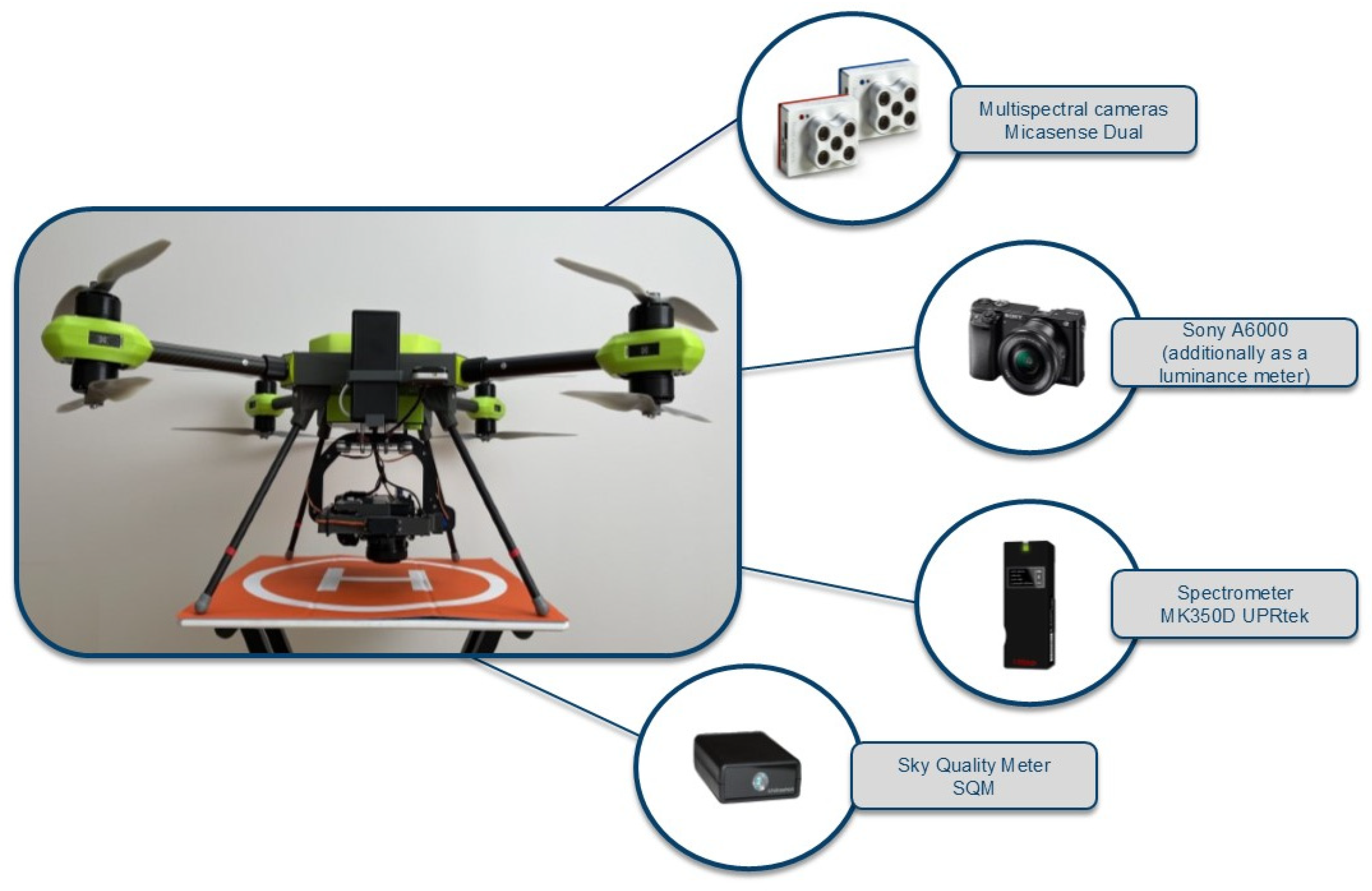
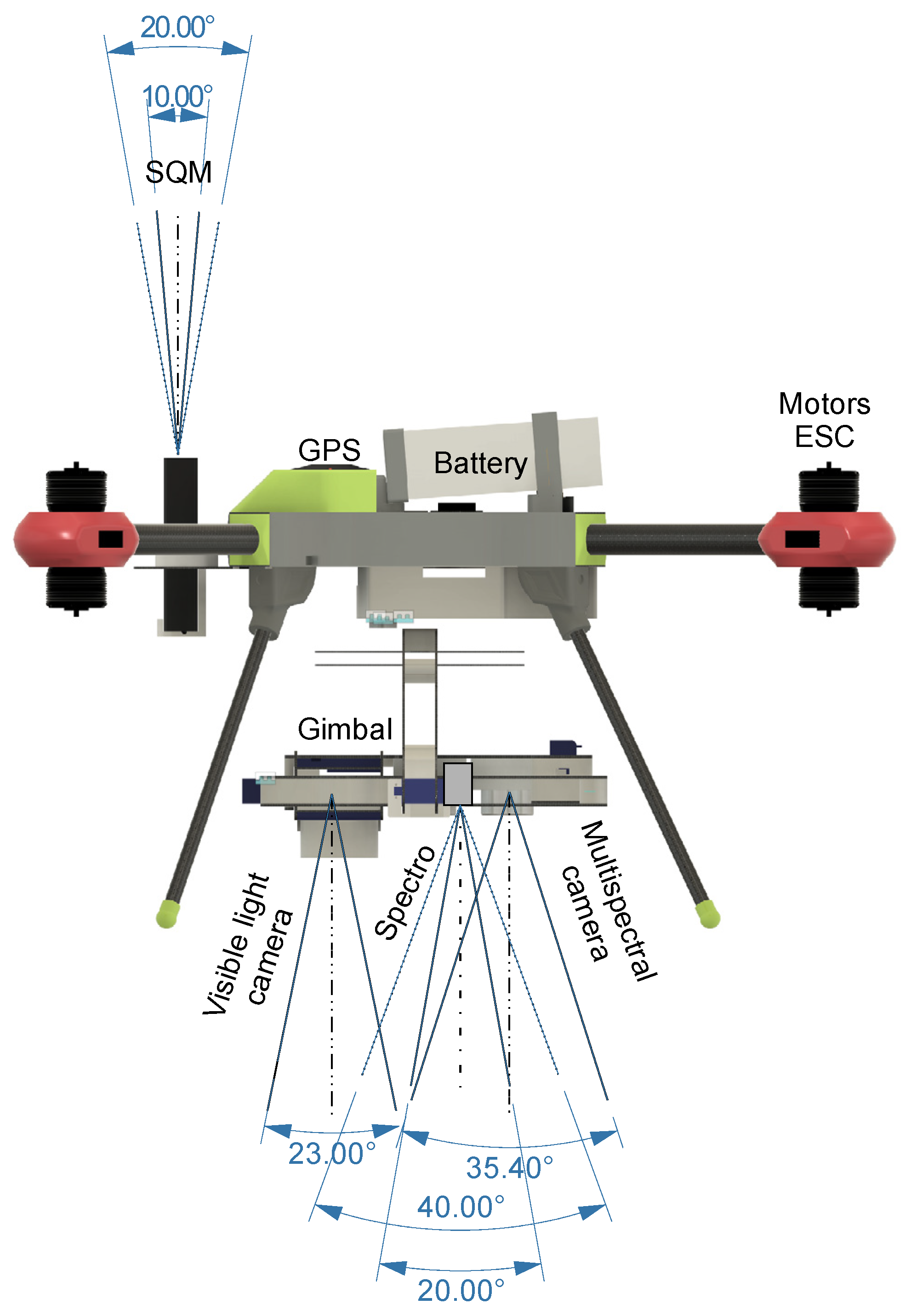
The measurement equipment (Figure 2), or in other words, the functional payload of the drone, is a number of different sensors designed to measure the light spectrum, both point-wise and over a certain area (Figure 3). Since the result of the measurements is a spatial map of the intensity and light spectrum in the area, two cameras are provided for this purpose—a visible light camera and a multispectral camera, which are placed on a common gimbal. The gimbal has been designed so that both cameras fit on a single structure, which ensures the constant mutual position and orientation of the two cameras. The two cameras are connected to the flight computer (FC) and are released according to the flight plan from pre-designed positions. The total weight of the mounted sensors is 1100 g. The recommended functional payload weight for the presented drone is 1500 g (the maximum allowable payload weight is 4000 g). The platform therefore still has a significant reserve of loading capacity, which allows for additional development and adaptation of more sensors. A summary of the measurement sensors and the data acquired, together with the units, is shown in Table 1.
For visible light registration, a Sony Alpha 6000 camera (Sony Corporation, Tokyo, Japan) (Figure 2) with an E PZ 16-50 mm F3.5-5.6 OSS lens was used, which offers decent technical performance at a relatively low price. This camera is often used for photogrammetry tasks [29,30]. This classic commercial camera, with the lens being part of the original kit, was used to acquire images from a low flight level. The essence is to acquire images during the night; however, images acquired during the day can also serve as a source of complementary information on the landform and land cover, e.g., in areas not illuminated by artificial light. In addition, the data from this camera provides more accurate data on the elevation model of the terrain. Both nighttime and daytime images are separate products analysed separately but also serve as input data for the derivative product of orthomosaics for the analysed area. Nighttime aerial orthophotos are increasingly being used as products for the analysis of light pollution. When developing low-light photogrammetric products, the decrease in the geometric accuracy of the model must be taken into account, as described in more detail in works [31,32,33].
The images from the aforementioned camera were also used as input data to obtain luminance information in units of cd/m2, recorded for individual locations (objects). The conversion of the visible light camera values into luminance values was carried out by using the commercial software iQ Luminance 3.1.0 (Image Engineering GmbH & Co. KG, Kerpen, Germany). The camera was calibrated in the software manufacturer’s laboratory to provide the luminance value. The calibration procedure consists of laboratory tests and the development of calibration coefficients for a specific set-up (camera including lens) [34]. The calibration tests were performed for given ISO exposure and aperture parameters, where the exposure time depends on the brightness of the opto-electronic conversion function (OECF), and for a specific focal length. The parameters for which the camera was calibrated were strictly defined for the conditions used during image capture. These parameters were determined during previous studies. This procedure allowed the acquisition of images representing luminance maps.
MicaSense MX Red and MX Blue equipment (AgEagle Aerial Systems Inc., Wichita, Kansas, USA) was used as multispectral cameras (Figure 3), which allowed synchronic recording of 10 spectral channels. This equipment is not yet widely used in the analysis of light pollution phenomena, but its potential for the evaluation of lighting frame spectra and their classification was nevertheless addressed by the authors in a publication [35].
These multispectral cameras directly capture a 12-bit image that is saved in a TIFF file and has to be calibrated. The radiometric calibration of the camera was carried out according to the following formula [36]:
L = V x , y a 1 g p p B L t e + a 2 y a 3 t e y ,
where
  • L is the spectral radiance in W/m2/sr/nm,
  • p is the normalised RAW pixel value,
  • p B L is the normalised black level value,
  • a 1   a 2 , a 3 are the radiometric calibration coefficients,
  • V(x, y) is the vignette polynomial function for pixel location (x, y),
  • t e is the image exposure time,
  • g is the sensor gain setting (can be found in metadata tags),
  • x, y are the pixel column and row number, respectively.
The effect of vignetting was corrected according to the following formula.
I c o r x , y = I x , y k ,
k = 1 + k 0 r + k 1 r 2 + k 2 r 3 + k 3 r 4 + k 4 r 5 + k 5 r 6 ,
r = x c x 2 + y c y 2
where
  • I c o r x , y is the corrected intensity of pixel at x,y,
  • I(x,y) is the original intensity of pixel at x,y,
  • k is the correction factor by which the raw pixel value should be divided to correct for vignette,
  • r is the distance of the pixel (x,y) from the vignette centre, in pixels,
  • (x,y) is the coordinate of the pixel being corrected,
  • c x , c y is the principal point orientation.
More on the issue of calibration of multispectral cameras for UAVs can be found in the article [37]. This study adopted the radiometric calibration method as above, although new, more precise solutions in this field are already available [38].
The SQM-type Unihedron Sky Quality Meter—LU-DL (Unihedron, Grimsby, Ontario, Canada) was used to measure the sky quality (Figure 3). This family of devices is widely and extensively used in light pollution analysis—in the assessment of sky brightness [22,39,40,41]. Data recording takes place in the instrument’s local memory. The sensor is powered from the drone’s power system. The drone is equipped with circuits that reduce and stabilise the voltage to the sensors. In the case of the SQM, the 5 V power supply is provided by the USB Type B connector that the SQM is equipped with. The SQM-LU-DL measures the darkness of the night sky to provide readings of the magnitudes per square arcsecond, abbreviated as mpsas and written mathematically as mag/arcsec2. Mpsas is a logarithmic measurement which means that large changes in sky brightness correspond to relatively small numerical changes. Data from SQM readings should be corrected for the ambient temperature. In this study, temperature correction of the readings was performed according to the method presented in the paper [42]:
S Q M c o r r = S Q M r e p 0.042 + 2.12 · 10 3 T
where
  • S Q M c o r r represents the corrected SQM values,
  • S Q M r e p means the measured SQM values,
  • T is the measured temperature at the measuring point.
The UPRtek MK350D spectrometer (Nanotech—UPRtek, Heerlen, The Netherlands) (Figure 3) was used for the point illumination analysis at the nadir position. This spectrometer is commonly used for light analysis in scientific research [43,44]. This device allows a complete summary of the photometric parameters of the illumination to be recorded. Data recording takes place in the local memory of the device.
All of the above devices have been mounted and integrated into the flight platform, the drone. Thus, at a single time and location, they are capable of simultaneous in-flight data acquisition. These devices are triggered remotely or programmed with a pre-set data acquisition time interval. In this way, once the time of measurement is synchronised with the time and position of the UAV, acquired from the drone’s on-board navigation system (GNSS—Global Navigation Satellite System), all the measurements are brought to the same time base and recorded in a geographical context (with an assigned geographical position), and this allows them to be visualised on a spatial map.

2.3. Product Specification

Table 2 provides a summary of all the products provided from the data collected by the equipment presented in this article. The table includes the type of data, the sensory source, the measured values and their units, and the sub-software that is used to process these data. It should be noted that not all the products are presented for the purposes of this article. The focus is on the most relevant products, according to the authors.

2.4. Experiment

An example research flight was designed and executed on the campus of the Gdansk University of Technology (Figure 4). The campus is a typical urban facility located within the city of Gdansk, a medium-sized city in Poland. The campus area is illuminated by street lamps and the buildings are illuminated by spotlights. The measurement conditions allowed measurements to be performed of sources of artificial illumination whose light beam falls in different directions. The most common case of recording artificial illumination through the measurement components of the drone located in the nadir direction is the case of recording light reflected from surfaces and objects in the research area. The weather conditions for the flight were good. The wind up to 50 m AGL did not exceed 2 m/s. Above 100 m, the wind increased to 4 m/s, cloudless sky, visibility > 10 km, flight start time 19:30 (UTC+1), sunset 17:59 (UTC+1), moon peak 20:06 (UTC+1), moon age 9.5 (visibility 74.9%), and moon altitude at start time 59.70 deg.
During the light pollution surveys presented here, three types of survey flights were carried out. The first flight was used to collect information about artificial lighting in the study area and was carried out to take an orthophoto map from a visible light camera and a multispectral camera. The drone then followed a pre-programmed route, hovering at the image-taking point to stabilise the flight. This procedure has been developed previously and is consistent with the research [31]. This flight was necessary to inventory the artificial lighting and determine its spectrum.
The second research flight was a flight along a pre-programmed route at an altitude of 100 m, with the take-off point in a dark position (take-off 1 in Figure 4). The purpose of this phase of the research was to mobile measure the SQM values in the study area. The third test flight was a vertical ascent at 200 m above ground level (AGL) in a fixed position with the take-off point located under a street lamp (take-off 2 in Figure 4), in a location illuminated by it.
During a typical survey flight, the UAV records all the necessary data with a fixed interval. In interval mode, data from the SQM (every 1 s), data from the visible light camera (every 1 s) and from the multispectral camera (every 1 s) and from the spectrometer (every 1 s) are recorded. At the operator’s request, targeted measurements can also be taken at a predetermined position from the spectrometer and visible light camera. All the instruments have the ability to trigger the shutter and take a measurement in a fixed position, which is the correct procedure for nighttime measurements. The nighttime measurement performs slightly differently than during the day. In photogrammetry with a UAV taken during the day, the drone does not stop when taking images. The exposure time is so short that the blur is practically invisible. However, when taking pictures at night, the drone has to enter a hover and reduce its forward speed to zero during the exposure. This is the only procedure that guarantees a minimal blur at the set exposure time. This is also how the UAV flight is programmed in the mission management software.

3. Results

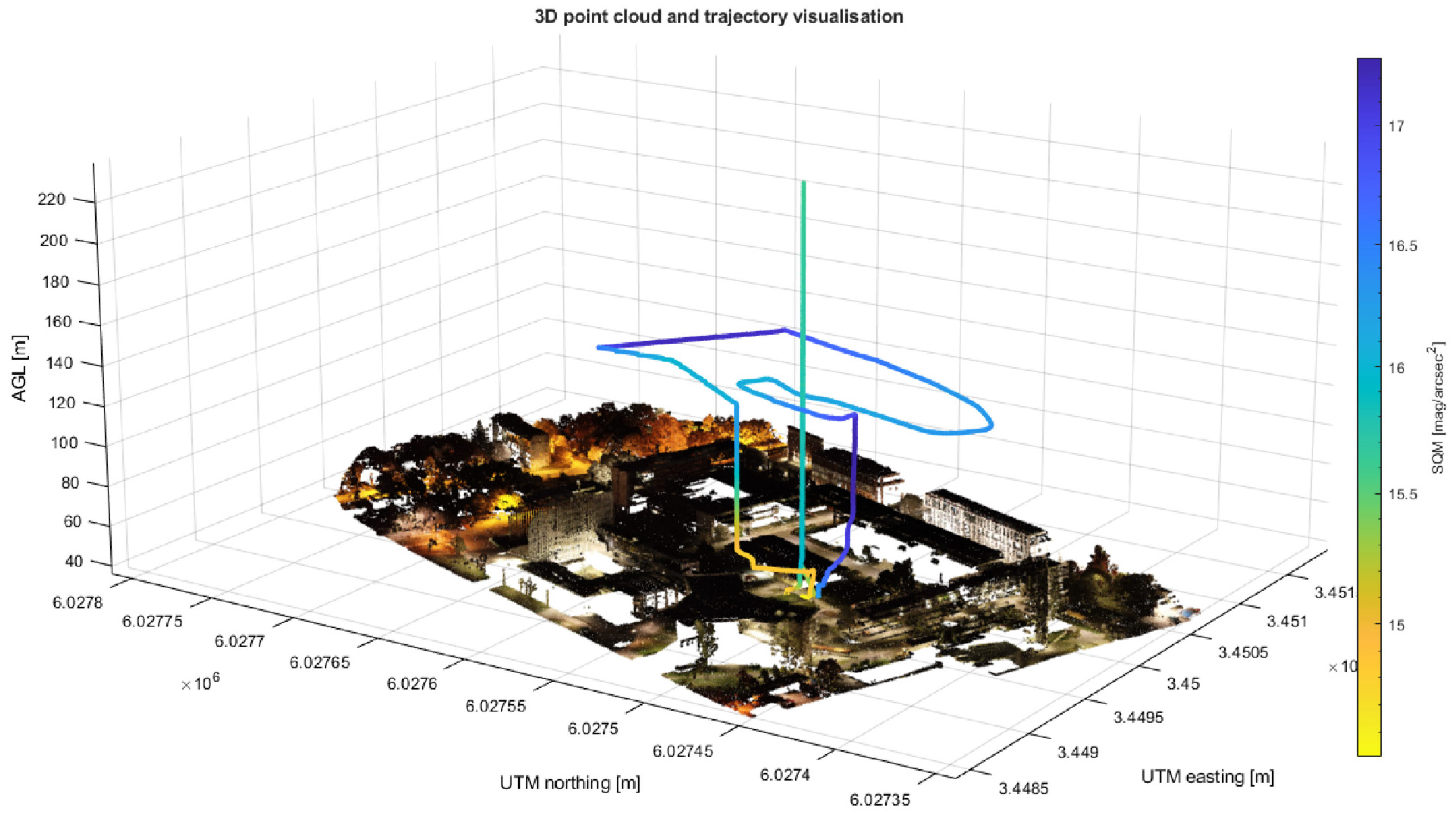
Figure 5 shows the point cloud from the night survey and the marked flight trajectory for survey flights 2 and 3. Survey flight 1, which was used to produce the orthophotos and point cloud, was based on a single grid route.

3.1. SQM

Figure 5 simply visualises the trajectory that the UAV has travelled during the flight and the colour-coded scale marks the readings of the SQM values during the different phases of the flight. The point cloud that forms the background of the figure was created as a result of a photogrammetric process based on the data collected in flight 1. As can be seen in this figure, the point cloud was generated correctly, and the colour of the individual points in the cloud makes it possible to locate the sources of illumination and the position of areas illuminated by a given light source. In parts where the illumination is insufficient, the point cloud is not generated, so it can be considered that the illumination of these regions is minimal. The research trajectory from the dark take-off (take-off 1) was over the streetlights at a height of 100 m. Significantly, the SQMs from the dark take-off already exceeded 16 mag/arcsec2, which cannot be said for the take-off (take-off 2) at the streetlight-illuminated site. In the case of a take-off from an illuminated location, the SQM values were above 14 mag/arcsec2, indicating a clear influence of the illumination on the instrument readings. From this, it follows that the SQM data must be considered in the context of the flight altitude. At low altitude, interference is introduced by artificial sources of illumination, so the measurements will be distorted. At a certain flight altitude, the SQM values fix at a certain value, which allows the quality of the sky to be objectively assessed.
Figure 6 shows the synchronised recording of the SQM values versus the flight altitude and the UAV’s momentary roll and pitch.
As can be seen in the plot above, when flying from a dark position (phase 1 in Figure 6) at altitudes up to 100 m, the SQM value was not stable, oscillating between 16 and 17 mag/arcsec2. Here, the researchers estimate that dynamic flight along a programmed route causes changes in the drone’s pitch and roll angles. In this way, the observation vector of the SQM device drastically changes the measured section of the sky (it is not zenithal). This finding is the first of its kind in the field of mobile sky quality measurements, so it requires further detailed research. This phenomenon can be seen when we compare the readings of the SQM values with the roll and pitch angles of the drone (Figure 6). It should be noted that the SQM is permanently mounted to the drone platform. Changing the tilt and roll angle of the drone also changes the viewing angle of the SQM and consequently changes the value readings. Technically, in the solution presented in this article, it was not possible to use a second gimbal placed on top of the platform to stabilise the viewing angle of the SQM. This was proposed by Ges et al. in [45], where the SQM measurements were performed from a floating platform, and the use of this solution on a flying platform seems reasonable.
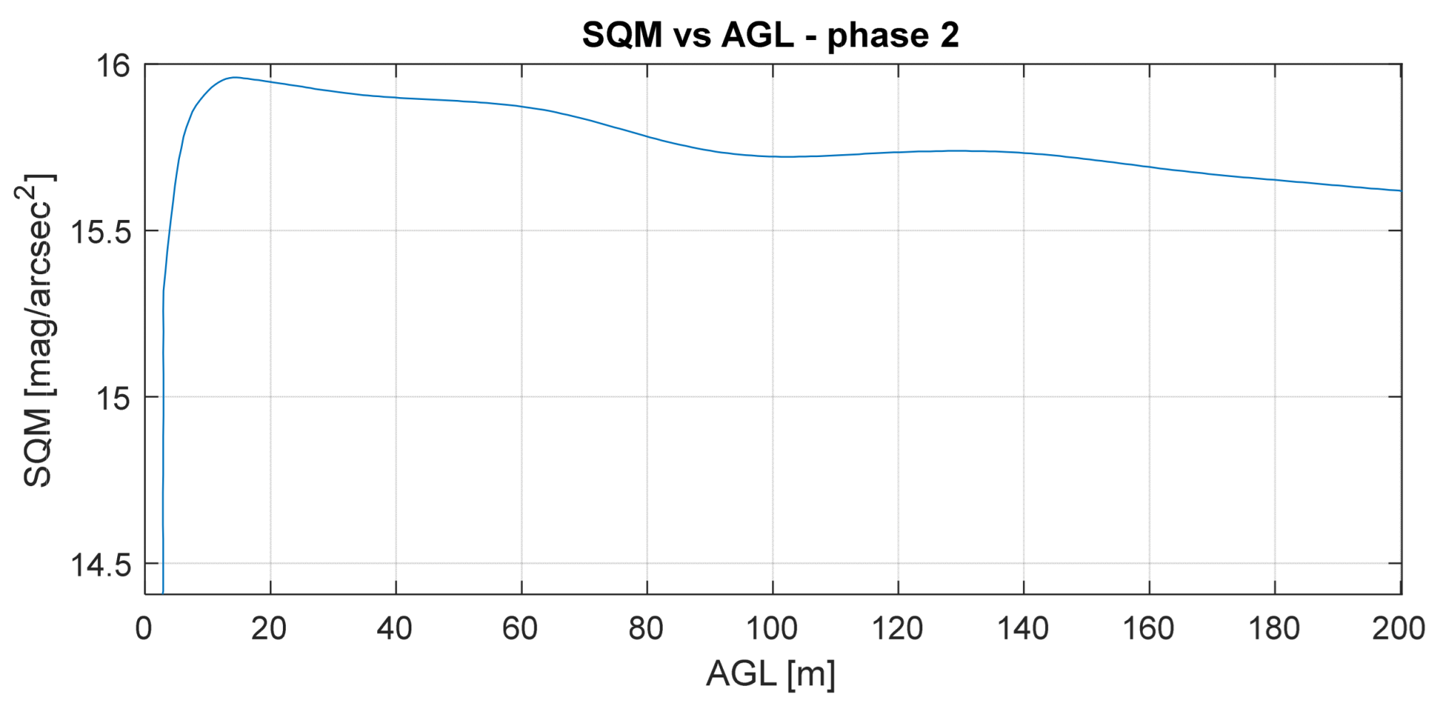
During the take-off from the take-off 2 light position (phase 2 in Figure 4), the flight was performed in a fixed position at an altitude of 200 m. Here, there is clearly an increase in the SQM values up to a certain altitude and stabilisation at a relatively constant value (around 16 mag/arcsec2). During the hovering flight, the effect of the dynamic pitch and roll angle change was eliminated, although it is clear that the drone will tilt in the direction of the wind at heights from about 100 m upwards (stable roll and pitch angle change to stabilise the position). This also caused a slight change in the value measured by the SQM.
Figure 7 shows the dependence of the SQM value with a change in the flight altitude (AGL—above ground level).
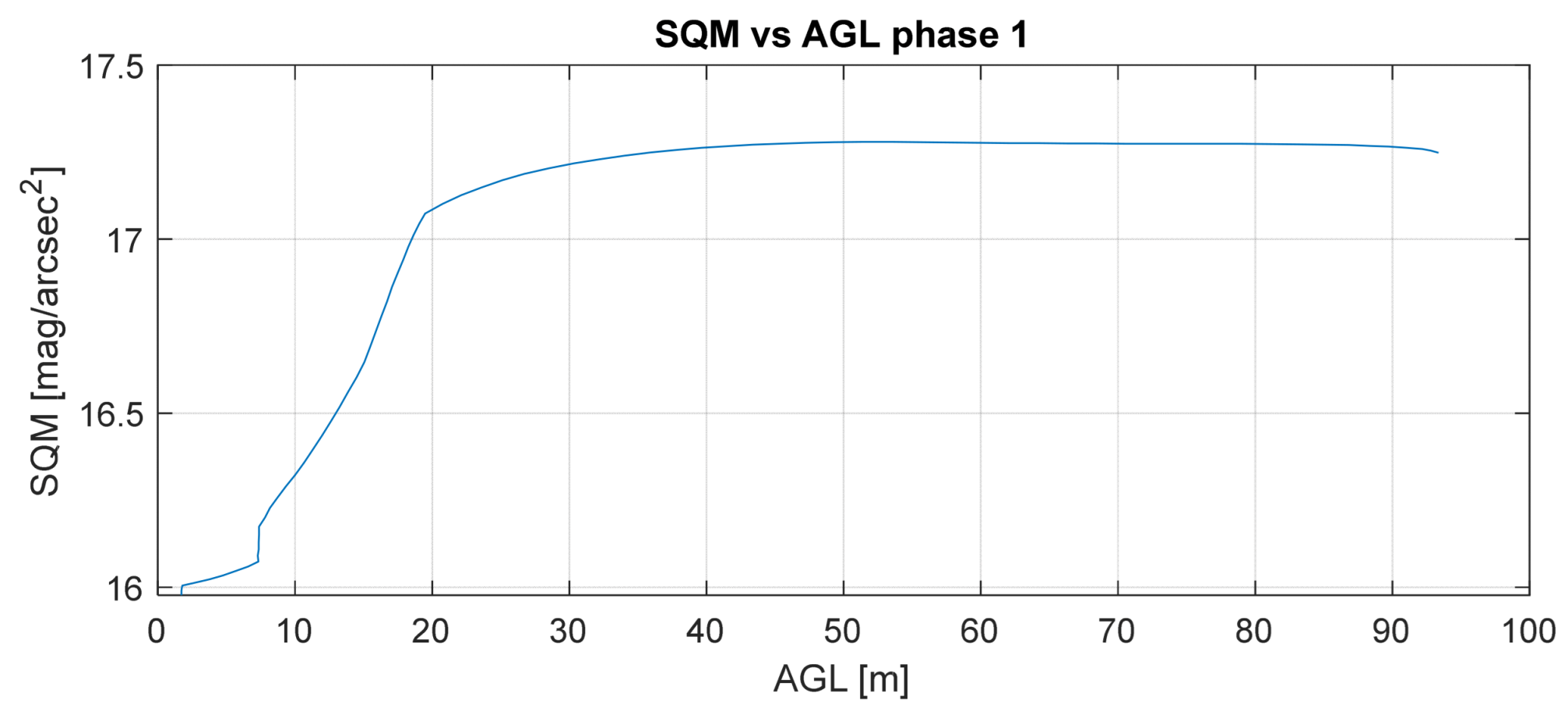
The SQM value increased significantly up to a height of about 10 m, after which it stabilised. A change in altitude above 10 m did not cause a significant change in the SQM value (apart from the change induced by the roll and pitch of the drone, as explained in the previous paragraph). These conclusions and results correspond with the research [46] up to exactly the same flight altitude. However, the researchers in [46] did not consider the effect of the roll and pitch angles on the stability of the measurement, which is due to the different methodology and design of the measurement device. The take-off in a shaded area (take-off 1) resulted in the effect of artificial lighting on the SQM values being small at the beginning but recorded by the instrument. Above 20 m, the values stabilised (Figure 8).
In the case of take-off from a shaded location (take-off 1), it can be seen that the SQM values reached higher than 17 mag/arcsec2, which does not correspond with the values during flight from take-off 2, where the SQM stabilised at a lower level, above 15.5 mag/arcsec2. Further analysis of Figure 6 shows that during the flight at an altitude of 100 m (80–500 seconds of flight), the SQM values fluctuated and oscillated between 16 and 17 mag/arcsec2, indicating that the SQM registered a different place in the sky that is differently illuminated (moon, stars, light pollution). This flight was dynamic and performed with a variable drone position (Figure 5) and, crucially, with variable pitch and roll. In this situation, it would be necessary to calculate the exact visual vector and specifically identify the point in the sky that was recorded by the SQM. A stable flight, from a lighted location, no longer presents the same problem, as the value stabilised at between 15.5 and 16 mag/arcsec2, looking almost directly vertical to the sky (taking into account the drone’s low pitch and roll while hovering). This means that this particular recorded part of the sky had the brightness as recorded by the SQM in a stable position. Dynamic registration of an SQM that is not stabilised relative to the vertical introduces new problems that need to be further addressed. For the moment, it can be assumed that hover flight is the correct measurement procedure for the SQM.

3.2. Nighttime Orthophoto Map

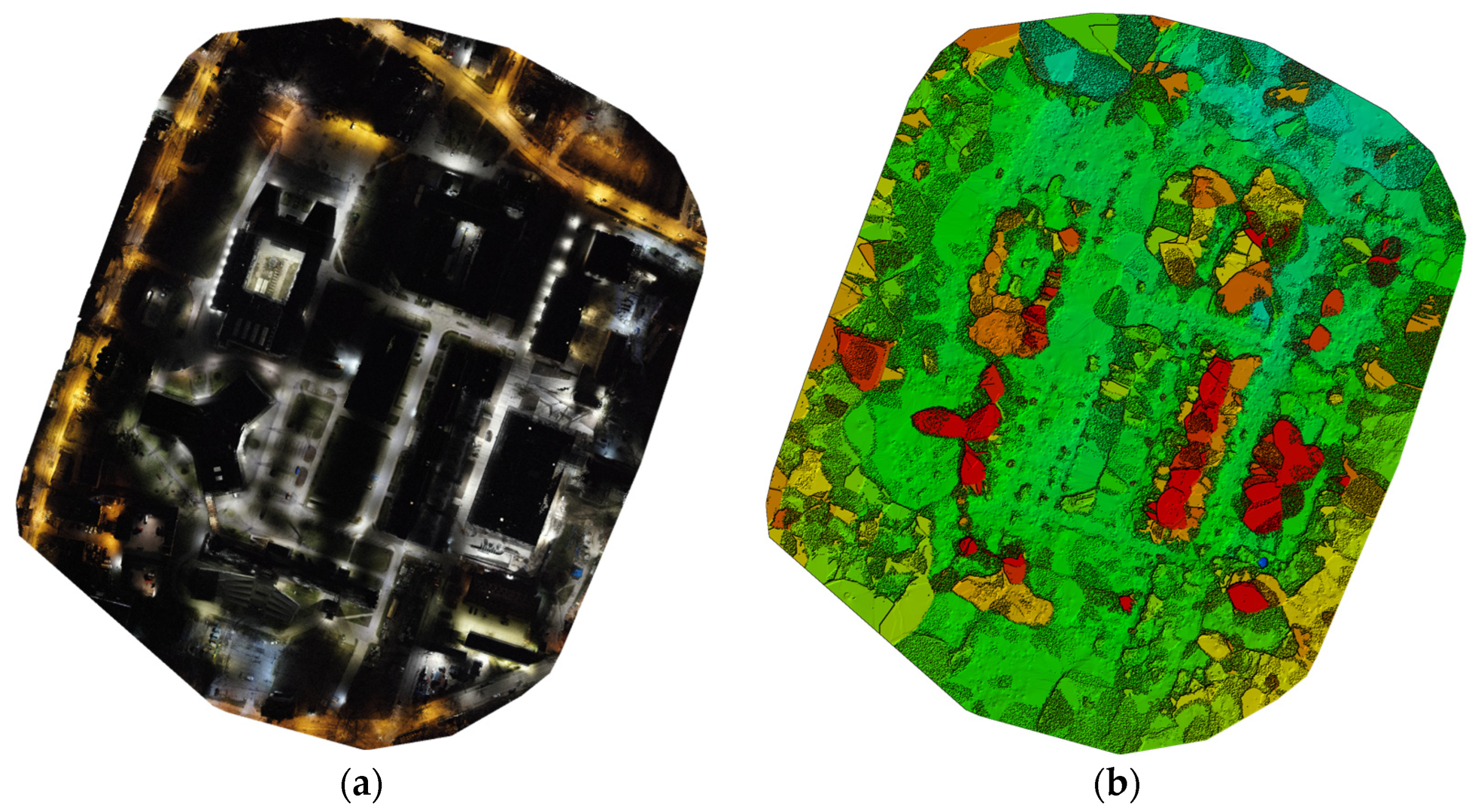
Figure 9 presents an overview of the nighttime orthophoto map and the numerical terrain model extracted from the nighttime images. As can be seen in the images shown, the designed shutter speed settings and the drone’s hovering performance allowed the acquisition of images without significant blur. These images allowed the production of a night orthophoto map and a digital surface model (DSM) of the study area (Figure 9). The nighttime orthophoto map allowed an inventory to be performed of the lighting sources and visualised the illumination of the study area in a way that is as accessible to the human eye as possible. The DSM is not correct and should not be developed on the basis of nighttime images. In areas where there is complete darkness, e.g., building roofs, terrain elevation data are not calculated. The numerical terrain model must be acquired during daytime photography.
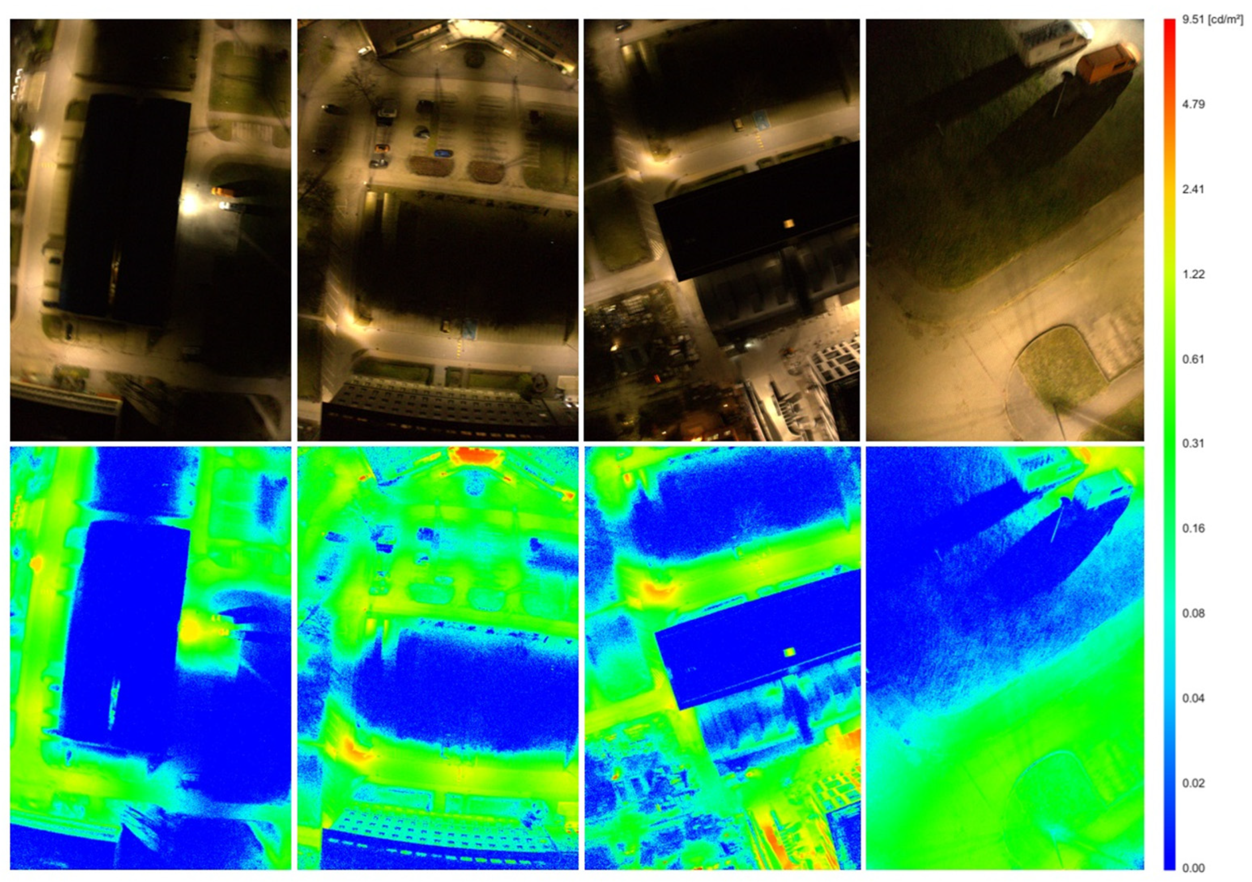
Figure 10 shows the raw and processed data from the visible light camera during flight. The source data from the camera allowed an analysis of the illuminance (Figure 10 bottom row), converted to cd/m2. Importantly, although the orthophoto map allowed visualisation of the study area, the pixel values did not represent objective illuminance values that can be compared with other objects or for intensity analysis. Only data converted into cd/m2 provide a measurement value.

3.3. Nighttime Multispectral Images

Figure 11 presents the composite image created from three spectral channels sequentially R (red 668(10) nm), G (green 560(20) nm) and B (blue—475(20) nm), as well as the radiance values for the indicated measurement point recorded in all ten spectral channels. The composite image was aligned and geometrically transformed based on the data contained in the spectral camera metadata.
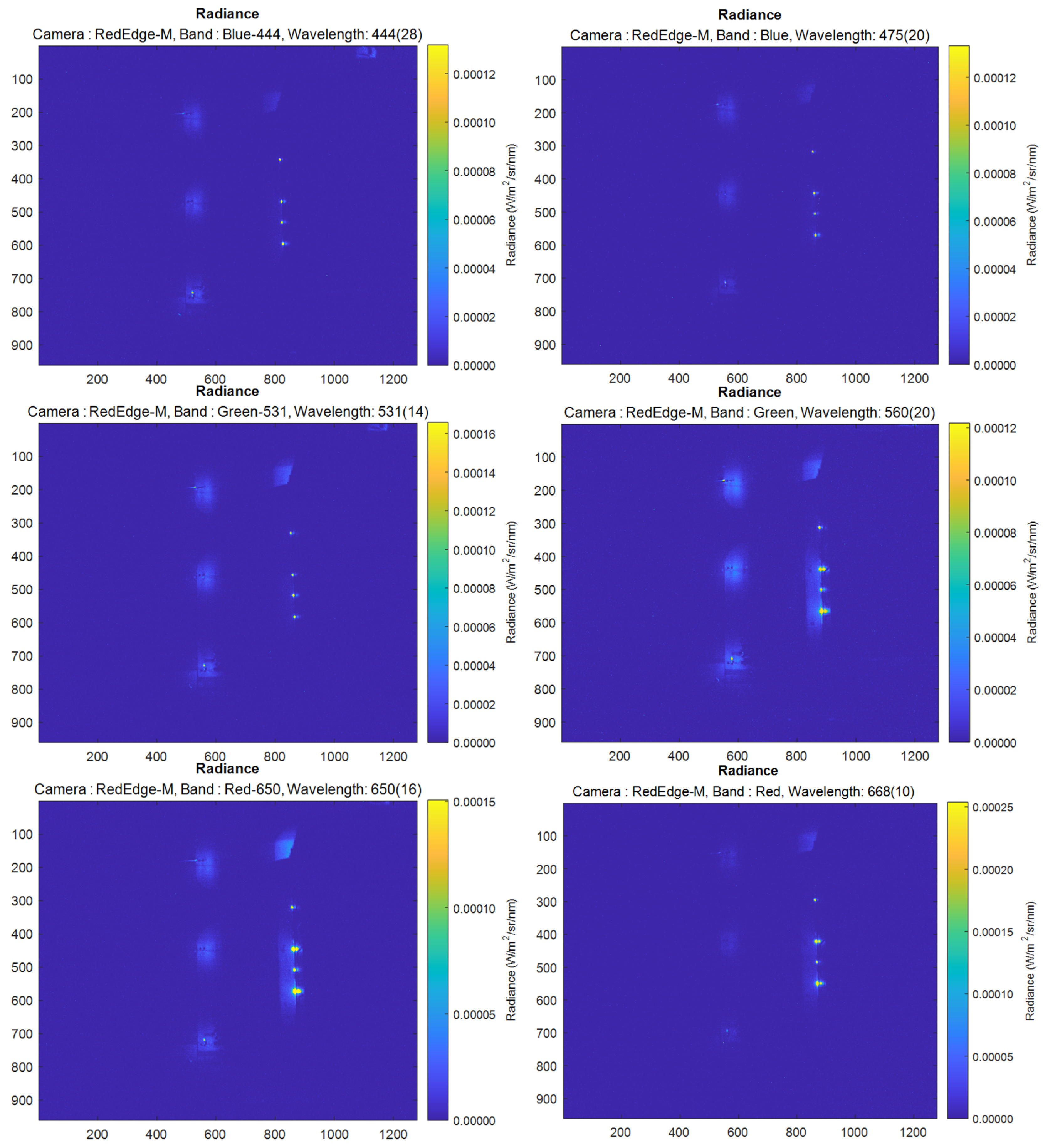
Analysis of the composite image in Figure 10 allowed the three extracted spectral channels to be displayed simultaneously. After marking the selected illumination source, here marked with a red point, it was possible to extract the radiance from all the spectral channels for this point (Figure 11). The recorded radiance was at a minimum level but was recorded in each spectral channel anyway. These data allowed classification of the selected sources and measurement of their spectrum. The radiance in each spectral channel separately is shown in the following Figure 12.
The comparison shown in Figure 12 proves that the multispectral camera can record artificial light sources at night in every channel. The halogen light source tested here, which illuminates a building in the study area, radiates in the full specular spectrum, so the camera records in every spectral channel.

4. Discussion and Conclusions

The market for the production of drones is developing rapidly. However, it should be noted that the majority of drones available for sale limit their versatility to the replacement of camera components. The problem of artificial light pollution monitoring is very complex, which is strongly linked to the lack of standardisation in the way pollution levels are assessed. It is important to note that a conventional camera is not sufficient to comprehensively assess this negative phenomenon. Specialised processing and supplementing of raster data from a classic RGB camera is not necessary. In order to integrate a larger number of sensors responsible for photometric measurements, it was necessary to move beyond the conventional commercial drones. The drone presented in this manuscript is the first drone built exclusively for artificial light pollution monitoring. The design of the drone, as well as the selected sensors, allow for joint integration as well as temporal synchronisation of the collected data.
The development of this design required an innovative technical approach. The use of this drone for research into methodologies for the assessment of artificial light pollution has allowed the simultaneous collection of multiple photometric data for the area of interest during a single flight. This approach provides data that are acquired under identical conditions (temporal, atmospheric, astronomical, etc.). The list of primary products that can be processed with a drone is very long, allowing a great deal of information to be acquired on the artificial lighting and sky brightness used. By supplementing the data with measurements taken during the day, we provide the possibility to verify artificial light pollution by correlating it with highly qualitative information on the spatial model of the analysed area.
The concept of building a UAV to measure light pollution required an out-of-the-box approach to platform design and sensor use. As part of the research, a new proprietary UAV platform was built for light pollution measurements, which is capable of carrying non-standard sensors, i.e., not originally designed to be mounted on the UAV and allowing for data rejections in the nadir and zenith directions at night and during the day.
Sensors not originally mounted on the UAV and not designed for mobile measurement purposes, especially the SQM and the spectrometer, allow new data to be acquired and new relationships to be discovered that have not yet been explored. In the present study, the SQM readings were analysed as a function of the flight altitude and launch site location. The data acquired confirmed those already studied by the team of Karpinisk et al. [46], but new problems requiring further research and the development of new methods were noted. Compensation of the SQM readings, caused by changes in the UAV roll and pitch angles during continuous measurements during dynamic flight, becomes an issue. The SQM reading changes as the angle changes, which seems natural due to the change in sky brightness depending on the azimuth. For dynamic measurement, such compensation seems to be necessary and it is planned to perform this task in future research. One technical proposal to solve this problem is to use an additional gimbal for the SQM measurements, which would be mounted on top of the drone. This would require designing a new device and mounting it on the drone.
A novelty presented in the present study is the use of a multispectral camera for the nighttime measurements. This is not a typical use of this type of camera, as there is no natural sunlight to reflect off the surfaces under study. This makes the traditional approach to calculating multispectral camera data meaningless and a new one is required, especially in the context of converting radiances into reflectances. Due to the apparent research gap in this area, the authors decided to focus only on the measurement of radiance and to adopt the development of a method for the calculation of non-fixed values such as irradiance and reflectance in future studies, should this be necessary in the context of light pollution measurements. In addition, it is worth noting that the shutter speed values for a multispectral camera suitable for daytime-only measurements are limited to a maximum of 1/60 and the camera software does not allow this time to be extended. This poses a problem when carrying out a measurement flight at night.
Several typical sensors used in photometry and photogrammetry are combined on the platform presented here. Photogrammetric sensors are not standardised for nighttime measurements, and photometric sensors are not adapted for UAV measurements. In this project, a methodology for nighttime measurements was developed and the photometric sensors were technically adapted for measurements from UAVs. The main aim of this was to maximise the amount of data collected during flight, so that the products are complementary and the data can be correlated with each other. With proper calibration, the measurement results are verifiable and the data are provided in terms of accepted units in the field of photometry.
The design presented here is the first of its kind, a specialised drone for light pollution measurement. In addition to the data provided that are mentioned in this manuscript, it allows for the collection of these data from a low aerial ceiling. Importantly, this is the flight altitude of migratory birds, which are negatively affected by light pollution.
The construction and research carried out highlighted the need for future research and further development of the UAV light pollution survey concept. As part of future research, the authors plan to carry out a case study with a focus on site-specific biodiversity research. The case study will allow the start of a long-term study of the impact of artificial lighting on fauna and flora.
Important progress will also be achieved in the full implementation of the solutions used here in the form of a uniform computer application. The software developed during this study in the form of scripts in the Python and MATLAB programming language works well but requires some knowledge on the part of the user. An application that automatises the data will definitely facilitate the work of future users. In addition, methods are required to automate the data analysis. This will not be possible without a case study and the development of new indicators for assessing the environment in relation to light pollution, which are also the subject of future research.
To summarise, this article presents a specialised drone developed specifically for light pollution measurements. A flying platform capable of carrying photogrammetric, remote sensing, sky quality sensors and a spectrometer was developed. The sensors used here, originally designed for daytime (multispectral cameras) and ground-based (SQM and spectrometer) measurements, were adapted and mounted on the UAV. As the results show, it is possible to use typical sensors for light pollution measurements from a UAV, and the data collected by the measurement system presented here provide a great amount of new information. The research presented here also reveals that the field of measuring light pollution from UAVs still needs to solve many problems, some of which are presented here.

Author Contributions

Conceptualisation, P.B. and K.B.; methodology, K.B.; software, P.B.; validation, P.B., K.B. and P.T.; formal analysis, K.B.; investigation, P.B., K.B. and P.T.; resources, K.B. and M.P.; data curation, K.B.; writing—original draft preparation, P.B. and K.B.; writing—review and editing, P.B., K.B. and P.T.; visualisation, P.B., K.B. and M.P.; supervision, K.B.; project administration, K.B.; funding acquisition, K.B. All authors have read and agreed to the published version of the manuscript.

Funding

The financial support for these studies from Gdansk University of Technology by the DEC-42/2020/IDUB/I.3.3 grant under the ARGENTUM—‘Excellence Initiative-Research University’ program is gratefully acknowledged.

Data Availability Statement

The original contributions presented in the study are included in the article, further inquiries can be directed to the corresponding author.

Conflicts of Interest

Author Mariusz Pulas was employed by the company Pelixar S.A. The remaining authors declare that the research was conducted in the absence of any commercial or financial relationships that could be construed as a potential conflict of interest.

References

  1. Grand View Research Commercial UAV Market Size, Share & Trends Analysis Report by Product (Fixed Wing, Rotary Blade, Nano, Hybrid), by Application (Agriculture, Energy, Government, Media & Entertainment, Construction), by Region, and Segment Forecasts, 2023–2030. 2022. Available online: https://www.grandviewresearch.com/industry-analysis/commercial-uav-market (accessed on 1 August 2024).
  2. Yao, H.; Qin, R.; Chen, X. Unmanned Aerial Vehicle for Remote Sensing Applications—A Review. Remote Sens. 2019, 11, 1443. [Google Scholar] [CrossRef]
  3. Kovanič, Ľ.; Topitzer, B.; Peťovský, P.; Blišťan, P.; Gergeľová, M.B.; Blišťanová, M. Review of Photogrammetric and Lidar Applications of UAV. Appl. Sci. 2023, 13, 6732. [Google Scholar] [CrossRef]
  4. Staniszewski, R.; Messyasz, B.; Dąbrowski, P.; Burdziakowski, P.; Spychała, M. Recent Issues and Challenges in the Study of Inland Waters. Water 2024, 16, 1216. [Google Scholar] [CrossRef]
  5. Kwon, D.Y.; Kim, J.; Park, S.; Hong, S. Advancements of Remote Data Acquisition and Processing in Unmanned Vehicle Technologies for Water Quality Monitoring: An Extensive Review. Chemosphere 2023, 343, 140198. [Google Scholar] [CrossRef] [PubMed]
  6. Szczurek, A.; Gonstał, D.; Maciejewska, M. The Gas Sensing Drone with the Lowered and Lifted Measurement Platform. Sensors 2023, 23, 1253. [Google Scholar] [CrossRef]
  7. Fadhil, M.J.; Gharghan, S.K.; Saeed, T.R. LoRa Sensor Node Mounted on Drone for Monitoring Industrial Area Gas Pollution. Eng. Technol. J. 2023, 195, 1152. [Google Scholar] [CrossRef]
  8. Rohi, G.; Ejofodomi, O.; Ofualagba, G. Autonomous Monitoring, Analysis, and Countering of Air Pollution Using Environmental Drones. Heliyon 2020, 6, e03252. [Google Scholar] [CrossRef]
  9. de Castro, A.I.; Shi, Y.; Maja, J.M.; Peña, J.M. UAVs for Vegetation Monitoring: Overview and Recent Scientific Contributions. Remote Sens. 2021, 13, 2139. [Google Scholar] [CrossRef]
  10. Su, S.; Yan, L.; Xie, H.; Chen, C.; Zhang, X.; Gao, L.; Zhang, R. Multi-Level Hazard Detection Using a UAV-Mounted Multi-Sensor for Levee Inspection. Drones 2024, 8, 90. [Google Scholar] [CrossRef]
  11. Jessin, J.; Heinzlef, C.; Long, N.; Serre, D. A Systematic Review of UAVs for Island Coastal Environment and Risk Monitoring: Towards a Resilience Assessment. Drones 2023, 7, 206. [Google Scholar] [CrossRef]
  12. Akhloufi, M.A.; Couturier, A.; Castro, N.A. Unmanned Aerial Vehicles for Wildland Fires: Sensing, Perception, Cooperation and Assistance. Drones 2021, 5, 15. [Google Scholar] [CrossRef]
  13. De Keukelaere, L.; Moelans, R.; Knaeps, E.; Sterckx, S.; Reusen, I.; De Munck, D.; Simis, S.G.H.; Constantinescu, A.M.; Scrieciu, A.; Katsouras, G.; et al. Airborne Drones for Water Quality Mapping in Inland, Transitional and Coastal Waters—MapEO Water Data Processing and Validation. Remote Sens. 2023, 15, 1345. [Google Scholar] [CrossRef]
  14. Zhao, C.; Li, M.; Wang, X.; Liu, B.; Pan, X.; Fang, H. Improving the Accuracy of Nonpoint-Source Pollution Estimates in Inland Waters with Coupled Satellite-UAV Data. Water Res. 2022, 225, 119208. [Google Scholar] [CrossRef] [PubMed]
  15. Bará, S.; Falchi, F. Artificial Light at Night: A Global Disruptor of the Night-Time Environment. Philos. Trans. R. Soc. B Biol. Sci. 2023, 378, 20220352. [Google Scholar] [CrossRef] [PubMed]
  16. Svechkina, A.; Portnov, B.A.; Trop, T. The Impact of Artificial Light at Night on Human and Ecosystem Health: A Systematic Literature Review. Landsc. Ecol. 2020, 35, 1725–1742. [Google Scholar] [CrossRef]
  17. Falcón, J.; Torriglia, A.; Attia, D.; Viénot, F.; Gronfier, C.; Behar-Cohen, F.; Martinsons, C.; Hicks, D. Exposure to Artificial Light at Night and the Consequences for Flora, Fauna, and Ecosystems. Front. Neurosci. 2020, 14, 602796. [Google Scholar] [CrossRef]
  18. Hölker, F.; Bolliger, J.; Davies, T.W.; Giavi, S.; Jechow, A.; Kalinkat, G.; Longcore, T.; Spoelstra, K.; Tidau, S.; Visser, M.E.; et al. 11 Pressing Research Questions on How Light Pollution Affects Biodiversity. Front. Ecol. Evol. 2021, 9, 767177. [Google Scholar] [CrossRef]
  19. Cupertino, M.D.C.; Guimarães, B.T.; Pimenta, J.F.G.; Almeida, L.V.L.D.; Santana, L.N.; Ribeiro, T.A.; Santana, Y.N. LIGHT POLLUTION: A Systematic Review about the Impacts of Artificial Light on Human Health. Biol. Rhythm. Res. 2023, 54, 263–275. [Google Scholar] [CrossRef]
  20. Hänel, A.; Posch, T.; Ribas, S.J.; Aubé, M.; Duriscoe, D.; Jechow, A.; Kollath, Z.; Lolkema, D.E.; Moore, C.; Schmidt, N.; et al. Measuring Night Sky Brightness: Methods and Challenges. J. Quant. Spectrosc. Radiat. Transf. 2018, 205, 278–290. [Google Scholar] [CrossRef]
  21. Fiorentin, P.; Bertolo, A.; Cavazzani, S.; Ortolani, S. Calibration of Digital Compact Cameras for Sky Quality Measures. J. Quant. Spectrosc. Radiat. Transf. 2020, 255, 107235. [Google Scholar] [CrossRef]
  22. Mander, S.; Alam, F.; Lovreglio, R.; Ooi, M. How to Measure Light Pollution—A Systematic Review of Methods and Applications. Sustain. Cities Soc. 2023, 92, 104465. [Google Scholar] [CrossRef]
  23. Zielinska-Dabkowska, K.M.; Szlachetko, K.; Bobkowska, K. An Impact Analysis of Artificial Light at Night (ALAN) on Bats. A Case Study of the Historic Monument and Natura 2000 Wisłoujście Fortress in Gdansk, Poland. Int. J. Environ. Res. Public Health 2021, 18, 11327. [Google Scholar] [CrossRef] [PubMed]
  24. Kurkela, M.; Maksimainen, M.; Julin, A.; Virtanen, J.-P.; Männistö, I.; Vaaja, M.T.; Hyyppä, H. Applying Photogrammetry to Reconstruct 3D Luminance Point Clouds of Indoor Environments. Archit. Eng. Des. Manag. 2022, 18, 56–72. [Google Scholar] [CrossRef]
  25. Bolliger, J.; Hennet, T.; Wermelinger, B.; Bösch, R.; Pazur, R.; Blum, S.; Haller, J.; Obrist, M.K. Effects of Traffic-Regulated Street Lighting on Nocturnal Insect Abundance and Bat Activity. Basic Appl. Ecol. 2020, 47, 44–56. [Google Scholar] [CrossRef]
  26. Bouroussis, C.A.; Topalis, F.V. Assessment of Outdoor Lighting Installations and Their Impact on Light Pollution Using Unmanned Aircraft Systems—The Concept of the Drone-Gonio-Photometer. J. Quant. Spectrosc. Radiat. Transf. 2020, 253, 107155. [Google Scholar] [CrossRef]
  27. Rabaza, O.; Molero-Mesa, E.; Aznar-Dols, F.; Gómez-Lorente, D. Experimental Study of the Levels of Street Lighting Using Aerial Imagery and Energy Efficiency Calculation. Sustainability 2018, 10, 4365. [Google Scholar] [CrossRef]
  28. Li, X.; Levin, N.; Xie, J.; Li, D. Monitoring Hourly Night-Time Light by an Unmanned Aerial Vehicle and Its Implications to Satellite Remote Sensing. Remote Sens. Environ. 2020, 247, 111942. [Google Scholar] [CrossRef]
  29. Aldao, E.; González-Jorge, H.; Pérez, J.A. Metrological Comparison of LiDAR and Photogrammetric Systems for Deformation Monitoring of Aerospace Parts. Measurement 2021, 174, 109037. [Google Scholar] [CrossRef]
  30. Saputra, H.; Ananda, F.; Dinanta, G.P.; Awaluddin, A.; Edward, E. Optimization of UAV-Fixed Wing for Topographic Three Dimensional (3D) Mapping in Mountain Areas. In Proceedings of the 11th International Applied Business and Engineering Conference, Riau, Indonesia, 21 September 2023; EAI: Newton, MA, USA, 2024. [Google Scholar]
  31. Burdziakowski, P.; Bobkowska, K. UAV Photogrammetry under Poor Lighting Conditions—Accuracy Considerations. Sensors 2021, 21, 3531. [Google Scholar] [CrossRef]
  32. Massetti, L.; Paterni, M.; Merlino, S. Monitoring Light Pollution with an Unmanned Aerial Vehicle: A Case Study Comparing RGB Images and Night Ground Brightness. Remote Sens. 2022, 14, 2052. [Google Scholar] [CrossRef]
  33. Bhattarai, D.; Lucieer, A. Optimising Camera and Flight Settings for Ultrafine Resolution Mapping of Artificial Night-Time Lights Using an Unoccupied Aerial System. Drone Syst. Appl. 2024, 12, 1–11. [Google Scholar] [CrossRef]
  34. Wüller, D.; Gabele, H. The Usage of Digital Cameras as Luminance Meters. In Digital Photography III; SPIE: Bellingham, WA, USA, 20 February 2007; Volume 6502, p. 65020U. [Google Scholar]
  35. Tate, C.G.; Moyers, R.L.; Corcoran, K.A.; Duncan, A.M.; Vacaliuc, B.; Larson, M.D.; Melton, C.A.; Hughes, D. Artificial Illumination Identification from an Unmanned Aerial Vehicle. J. Appl. Remote Sens. 2020, 14, 34528. [Google Scholar] [CrossRef]
  36. Suport Micasense Radiometric Calibration Model for MicaSense Sensors. Available online: https://support.micasense.com/hc/en-us/articles/115000351194-Radiometric-Calibration-Model-for-MicaSense-Sensors (accessed on 1 August 2024).
  37. Daniels, L.; Eeckhout, E.; Wieme, J.; Dejaegher, Y.; Audenaert, K.; Maes, W.H. Identifying the Optimal Radiometric Calibration Method for UAV-Based Multispectral Imaging. Remote Sens. 2023, 15, 2909. [Google Scholar] [CrossRef]
  38. Mamaghani, B.; Salvaggio, C. Multispectral Sensor Calibration and Characterization for SUAS Remote Sensing. Sensors 2019, 19, 4453. [Google Scholar] [CrossRef]
  39. Puschnig, J.; Wallner, S.; Schwope, A.; Näslund, M. Long-Term Trends of Light Pollution Assessed from SQM Measurements and an Empirical Atmospheric Model. Mon. Not. R. Astron. Soc. 2022, 518, 4449–4465. [Google Scholar] [CrossRef]
  40. Bustamante-Calabria, M.; de Miguel, A.; Martín-Ruiz, S.; Ortiz, J.-L.; Vílchez, J.M.; Pelegrina, A.; García, A.; Zamorano, J.; Bennie, J.; Gaston, K.J. Effects of the COVID-19 Lockdown on Urban Light Emissions: Ground and Satellite Comparison. Remote Sens. 2021, 13, 258. [Google Scholar] [CrossRef]
  41. Ściężor, T. Effect of Street Lighting on the Urban and Rural Night-Time Radiance and the Brightness of the Night Sky. Remote Sens. 2021, 13, 1654. [Google Scholar] [CrossRef]
  42. Schnitt, S.; Ruhtz, T.; Fischer, J.; Hölker, F.; Kyba, C.C.M. Temperature Stability of the Sky Quality Meter. Sensors 2013, 13, 12166–12174. [Google Scholar] [CrossRef]
  43. Luo, W.; Kramer, R.; Kompier, M.; Smolders, K.; de Kort, Y.; van Marken Lichtenbelt, W. Personal Control of Correlated Color Temperature of Light: Effects on Thermal Comfort, Visual Comfort, and Cognitive Performance. Build. Environ. 2023, 238, 110380. [Google Scholar] [CrossRef]
  44. Burdziakowski, P. The Effect of Varying the Light Spectrum of a Scene on the Localisation of Photogrammetric Features. Remote Sens. 2024, 16, 2644. [Google Scholar] [CrossRef]
  45. Ges, X.; Bará, S.; García-Gil, M.; Zamorano, J.; Ribas, S.J.; Masana, E. Light Pollution Offshore: Zenithal Sky Glow Measurements in the Mediterranean Coastal Waters. J. Quant. Spectrosc. Radiat. Transf. 2018, 210, 91–100. [Google Scholar] [CrossRef]
  46. Karpińska, D.; Kunz, M. Vertical Variability of Night Sky Brightness in Urbanised Areas. Quaest. Geogr. 2023, 42, 5–14. [Google Scholar] [CrossRef]
Figure 1. Drone view: (a) bottom view, (b) side view, (c) top view, and (d) front view.
Drones 08 00504 g001
Figure 2. Overview of the drone measurement components.
Drones 08 00504 g002
Figure 3. Sensor arrangement and sectors of operation.
Drones 08 00504 g003
Figure 4. The campus of the Gdansk University of Technology is illuminated by street lamps and spotlights, marked starting points in the non-illuminated area (no. 1) and under the street lamp in the illuminated area (no. 2).
Drones 08 00504 g004
Figure 5. Survey flights 2 and 3 and the night survey point cloud and SQM values marked on the trajectory in the corresponding colour.
Drones 08 00504 g005
Figure 6. Measurement of the SQM versus the UAV flight altitude and UAV roll and pitch angles.
Drones 08 00504 g006
Figure 7. Take-off 2—relationship of the SQM value to the altitude.
Drones 08 00504 g007
Figure 8. Take-off from a non-lighted area (take-off 1)—relationship of the SQM value to the height.
Drones 08 00504 g008
Figure 9. (a) Orthophoto map of the study area at night, and (b) digital surface model (DSM).
Drones 08 00504 g009
Figure 10. Images acquired with a visible light camera mounted on a drone (top row—raw data, bottom row—data indicating luminance level (cd/m2) after post-processing with iQ Luminance software).
Drones 08 00504 g010
Figure 11. (a) Composite image (colour composite) from spectral channels 3, 2, 1 (R, G and B), with the spectral measurement spot marked in red, and (b) spectral measurement result, radiance values at the spot for each spectral channel.
Drones 08 00504 g011
Figure 12. Comparison of the radiance images in the individual spectral channels for an example section of the study area.
Drones 08 00504 g012aDrones 08 00504 g012b
Table 1. Measurement sensor specifications.
TypeHorizontal FOV
(deg)
Vertical FOW (deg)Resolution (pix)Spectral Range (Bandwidth) (nm)Data TypeResult DataUnitsSensor
Weight
Visible light Camera36° 23°6000 × 4000 Image
(RAW)
Spectral
radiance
W/m2/nm/sr344 g body
116 g lens
Spectrometer~20°—HWHM *
~40°—FWHM **
~20°—HWHM *
~40°—FWHM **
380 to 780 nm
(1 nm)
Text (CSV)Illuminance, Spectral Power Distributionlux,
mW/m2
70 g
Sky Quality Meter~10°—HWHM *
~20°—FWHM **
~10°—HWHM *
~20°—FWHM **
Text (CSV) mag/arcsec2110 g
Multispectral
camera
47.2°35.4°1280 × 960coastal blue 444(28)
blue 475(32)
green 531(14)
green 560(27)
red 650(16)
red 668(14)
red edge 705(10)
red edge 717(12)
red edge 740(18)
NIR 842(57)
Image 12 bit (TIFF) 460 g
* Half width at half maximum; ** Full width at half maximum.
Table 2. Specification of the basic drone products.
ProductData TypeSource—SensorValues/UnitsTreatment/Processing Type (Whether Directly—Raw or after Using Software—Which)
RGB imagesRasterSony Alpha 6000 with E PZ 16–50 mm F3.5-5.6 OSS lensDN [-]Raw file
RGB imagesRasterSony Alpha 6000 with E PZ 16–50 mm F3.5-5.6 OSS lensSurface brightness [-]MATLAB R2024a
Images—luminance valuesRasterSony Alpha 6000 with E PZ 16–50 mm F3.5-5.6 OSS lensSurface luminance [cd/m2]iQ Luminance 3.1.0.
RGB daytime orthomosaicsRasterSony Alpha 6000 with E PZ 16–50 mm F3.5-5.6 OSS lensSurface brightness [-]Agisoft Metashape Professional 2.1.3.
Sky brightnessPointSQM LU-DLSky brightness [mag/arcsec2].Raw file
Photometric data from the spectrometerPointUPRtek MK350DIlluminance [lux], CCT [K], CIE Chromaticity Coordinates [-], CRI, Percent Flicker [%], Spectral Power Distribution (SPD) [mW/m2], λp [nm], Blue Light Weighted Irradiance (Eb) w/m2, Blue Light Hazard Efficacy of Luminous Radiation (Kbv) [w/lm], Blue Light Hazard Blue-ray % (BL%), Blue Light Hazard Risk Group (RG)Raw file
Multispectral images night RasterMicaSense Dual RedEdge-MX, RedEdge-MX BlueDN [-]Raw file/processed
Multispectral images night RasterMicaSense Dual RedEdge-MX, RedEdge-MX BlueRadiance (W/m2/sr/nm)MATLAB R2024a/Python 2.12.6/OpenCV 4.10.0
Orthomosaics for 9 spectral channels RasterMicaSense Dual RedEdge-MX, RedEdge-MX Blue Agisoft Metashape Professional 2.1.3
Disclaimer/Publisher’s Note: The statements, opinions and data contained in all publications are solely those of the individual author(s) and contributor(s) and not of MDPI and/or the editor(s). MDPI and/or the editor(s) disclaim responsibility for any injury to people or property resulting from any ideas, methods, instructions or products referred to in the content.