You are currently viewing a new version of our website. To view the old version click .
Drones
  • Article
  • Open Access

30 November 2024

Optimized Autonomous Drone Navigation Using Double Deep Q-Learning for Enhanced Real-Time 3D Image Capture

,
,
,
and
1
Escuela Politécnica Superior, Universidad Francisco de Vitoria, 28223 Pozuelo de Alarcón, Spain
2
Department of Science, Computing and Technology, Universidad Europea de Madrid, 28670 Villaviciosa de Odón, Spain
*
Author to whom correspondence should be addressed.
This article belongs to the Special Issue UAVs for Photogrammetry, 3D Modeling, Obtrusive Light and Sky Glow Measurements

Abstract

The proposed system assists in the automatic creation of three-dimensional (3D) meshes for all types of objects, buildings, or scenarios, using drones with monocular RGB cameras. All these targets are large and located outdoors, which makes the use of drones for their capture possible. There are photogrammetry tools on the market for the creation of 2D and 3D models using drones, but this process is not fully automated, in contrast to the system proposed in this work, and it is performed manually with a previously defined flight plan and after manual processing of the captured images. The proposed system works as follows: after the region to be modeled is indicated, it starts the image capture process. This process takes place automatically, with the device always deciding the optimal route and the framing to be followed to capture all the angles and details. To achieve this, it is trained using the artificial intelligence technique of Double Deep Q-Learning Networks (reinforcement learning) to obtain a complete 3D mesh of the target.

1. Introduction

1.1. Context and Justification

The integration of UAVs with advanced Deep Learning (DL) techniques has revolutionized autonomous navigation and the detection of structural damage in various environments. These advances enable drones to operate autonomously and are used in sectors such as the military, civil, and space sectors [1,2]. UAVs, which were traditionally manually controlled, can now employ autonomous navigation systems and pattern recognition to enhance their performance in complex environments, facilitating obstacle avoidance and precise navigation [3,4]. Route planning is an essential component, as it involves generating optimal trajectories that allow for efficient navigation while avoiding obstacles in both indoor and outdoor environments.
In natural environments such as forests and rivers where obstacles include trees and terrain variations, route planning becomes more challenging. In this context, advanced Artificial Intelligence (AI)-based systems like reinforcement learning (RL) are required to develop robust navigation strategies. Lee A. et al. [5] proposed the automatic creation of 3D meshes of natural objects and buildings using drones, which can autonomously determine the route and framing to capture all the necessary angles. Simulation experiments have shown a 97.7% accuracy in locating navigation points in environments such as forests.
To overcome the challenges in river environments, Wang Z. et al. [6] developed a realistic simulation environment in Unity, integrating advanced RL techniques and Learning from Demonstration (LfD) with Proximal Policy Optimization (PPO). The system achieved high levels of accuracy in autonomous navigation while adapting to adverse conditions [7]. Additionally, the use of geometric shape detection techniques and binary transformations enables precise obstacle avoidance [3,4], overcoming the limitations of GPS-based systems, which are vulnerable to interference [8].
Modern UAVs also employ advanced imaging capabilities to generate detailed terrain maps, such as orthophotos and multispectral maps, which are crucial for safe navigation in dynamic environments [9]. Deep learning algorithms like Generative Adversarial Networks (GANs) and Convolutional Neural Networks (CNNs) have revolutionized real-time object detection and semantic segmentation, which are essential in applications like precision agriculture and disaster responses [10,11].
Recent studies have also demonstrated the effectiveness of UAVs in inspecting critical infrastructures through visual and thermographic methods [10], reducing inspection times and improving the analysis of structural changes in challenging environments [12]. Additionally, deep learning techniques have been applied in crack segmentation and structural damage detection, improving the frequency and efficiency of inspections [13,14].

1.2. Motivation and Problem Definition

In a previous study, 3D meshes were generated in real time through a drone’s manual piloting, and the results can be seen in Figure 1, where the image captured by the drone and its reconstruction as a 3D mesh in real time are shown [15]. The challenge has been to complete the autonomous navigation aspect, which receives feedback from the generation of the 3D mesh as well as from environmental perception. This requires real-time effort for short- and medium-term planning of the next actions to be executed by the aircraft.
Figure 1. (a) Frame of the video captured by the drone. (b) Textured three-dimensional model. (c) Three-dimensional mesh with triangles [15].
This work is particularly interesting as it introduces a multidisciplinary approach that integrates photogrammetry using UAVs and advanced Artificial Intelligence (AI) techniques. In previous work we described the development of a real-time 3D reconstruction system that uses Artificial Intelligence techniques to achieve precise and efficient reconstructions of 3D environments using drones, combining unmanned aerial vehicles (drones) with sophisticated Computer Vision (CV) techniques such as Curvature-guided Dynamic Scale Multi-view Stereo Networks (CDS-MVSNets) and Deep Visual Odometry and Implicit Differentiable Simultaneous Localization and Mapping (DROID-SLAM) to design and develop a system that automatically generates high-quality point clouds and 3D meshes. This approach significantly reduces the time needed to create 3D models and improves their quality, facilitating an elevated level of automation through the constructive interaction between drone technology and CV [15].
This functionality is, therefore, of great interest and utility for industry. In fact, the obtained meshes could be used to create models of buildings and heritage assets, monitor unauthorized constructions/changes in any environment, observe changes in land in situations of natural disasters such as the eruption of the La Palma volcano (Spain) in 2021 [16] or the devastating fires in 2022 (Spain) [17], and assist in carrying out accident investigations in multiple traffic accidents by creating a mesh of the scene, among many other examples.
The increasing utilization of drones for 3D reconstruction through photogrammetry has brought forth significant challenges that hinder their efficiency and effectiveness. Key issues include limited battery life, prolonged flight times, and suboptimal flight paths, which collectively impact the quality and timeliness of image capture. For instance, drones like those equipped with DJI Terra [18,19] offer some commercial solutions for photogrammetry, allowing users to adjust certain parameters manually. However, it has been observed that an overall satisfactory output can often be achieved using default settings, which may not be optimal for every scenario.
One of the primary motivations behind our work is the short lifespan of drone batteries during flights. As the battery drains, the drone’s operational capabilities diminish, leading to potential incomplete data capture of the target area. This underscores the necessity for efficient path planning that minimizes flight distance while maximizing area coverage, particularly when documenting complex structures such as buildings.
Moreover, while commercial solutions enable automatic path calculation based on the designated area—often employing Boustrophedon patterns with interleaved distances, as shown in Figure 2—these paths are not always optimal. This inefficiency reaffirms another critical motivation: the time-consuming nature of covering an entire area. The reliance on predefined patterns often leads to longer routes, further draining battery life and extending operational times.
Figure 2. Boustrophedon trajectory applied to a perimeter of an olive field [20].
Another important motivation is that LiDAR-enabled equipment is expensive and not as widely available in the public domain.

1.3. Objectives of This Study

The initial hypothesis of this research line suggests that the automatic creation of 3D meshes of objects, buildings, or scenarios using drones is a valuable tool for multiple professional disciplines, as well as for industry in general. This work is the continuation of the line of research and work previously published by the authors [15], where the hypothesis was partially validated by developing a system that allows real-time 3D mesh generation. However, navigation could not be automated at that moment and required the intervention and participation of a pilot to carry it out.
Therefore, this study proposes the hypothesis that this activity can be fully automated, equipping drones with intelligence that allows them to capture the complete mesh based on autonomous and real-time navigation and image capture decisions according to their perception of the environment to be processed.
This study focuses on optimizing the autonomous navigation of drones to facilitate the efficient capture of images (using RGB cameras) necessary for the generation of 3D meshes. While creating high-quality meshes is a future objective, the primary focus of this work is to design a navigation system that enhances the effectiveness of data capture in outdoor environments. More specifically, the following objectives are proposed to validate this hypothesis:
  • Identify a suitable drone for the project equipped with a high-quality monocular RGB camera and programmable via a Software Development Kit (SDK), ensuring the ability to optimize its navigation.
  • Design an autonomous navigation system that enables real-time image capture, aimed at covering large outdoor areas while optimizing the drone’s trajectory based on its perception of the environment to fully capture the targets with the shortest possible path, with the consequent battery saving.
  • Integrate and validate the 3D mesh generation subsystems with the navigation subsystem, creating a demonstrative prototype that showcases the system’s effectiveness in data capture for subsequent mesh processing.

1.4. Contributions of This Work

Importantly, it should be noted that photogrammetry is typically regarded as a post-processing task. Yet, our approach integrates photogrammetry in a manner that enables real-time point cloud reconstruction, addressing the limitations of current methodologies. A key contribution of this work is the application of Deep Q-Learning (specifically, a Deep Q-network or DQN for short) in the navigation of drones, allowing for the efficient capture of data during flight.
Using a DQN is particularly relevant in this context, as it provides a well-established framework for reinforcement learning that has shown promising results in various domains, including robotic navigation. While alternative techniques, such as Proximal Policy Optimization (PPO), exist, our choice to implement a DQN was driven by its robustness and proven effectiveness in tackling complex decision-making problems in dynamic environments. This choice not only aligns with current research trends but also enhances the reliability of our system.
By developing a system that is not only more accessible but also optimized for resource management, our work aims to offer significant improvement over existing commercial solutions. The proposal seeks to enhance the operational capabilities of drones in 3D reconstruction, making a relevant contribution to the field. Through the integration of a DQN, we expect to achieve more effective path planning and data collection, ultimately facilitating a more efficient reconstruction process. Another important aspect is the possibility of using low-cost drones that, using only their RGB camera (without LIDAR), allow the task of mesh generation with total autonomy.

3. Materials and Methods

For the implementation of the proof of concept, the following tools and algorithms were used: OpenCV [43], MVSNet [44], DROID-SLAM [45], Meshroom [46], and Open3D [47]. In addition, the Poisson Surface Reconstruction (PSR) algorithm was used for exporting 3D meshes, the Flask framework for creating a web interface to control the drone, and FFmpeg for decoding the video signal emitted by the drone. Furthermore, new algorithms were designed and coded, which, together with the integration of the other ones, form the system: a DDQN algorithm with Prioritized Experience Replay for autonomous navigation and the point cloud distance calculation module. The combination of a DDQN with Prioritized Experience Replay provides an optimal balance between stability, accuracy, and efficiency in learning, allowing the agent to develop effective policies in complex and high-dimensional environments. The use of the DDQN mitigates the overestimation problem of DQNs, while Prioritized Experience Replay accelerates the learning process by focusing on the most significant experiences. This technological choice has been fundamental to the success of this study, enabling the implementation of robust and scalable solutions in the applied domain.

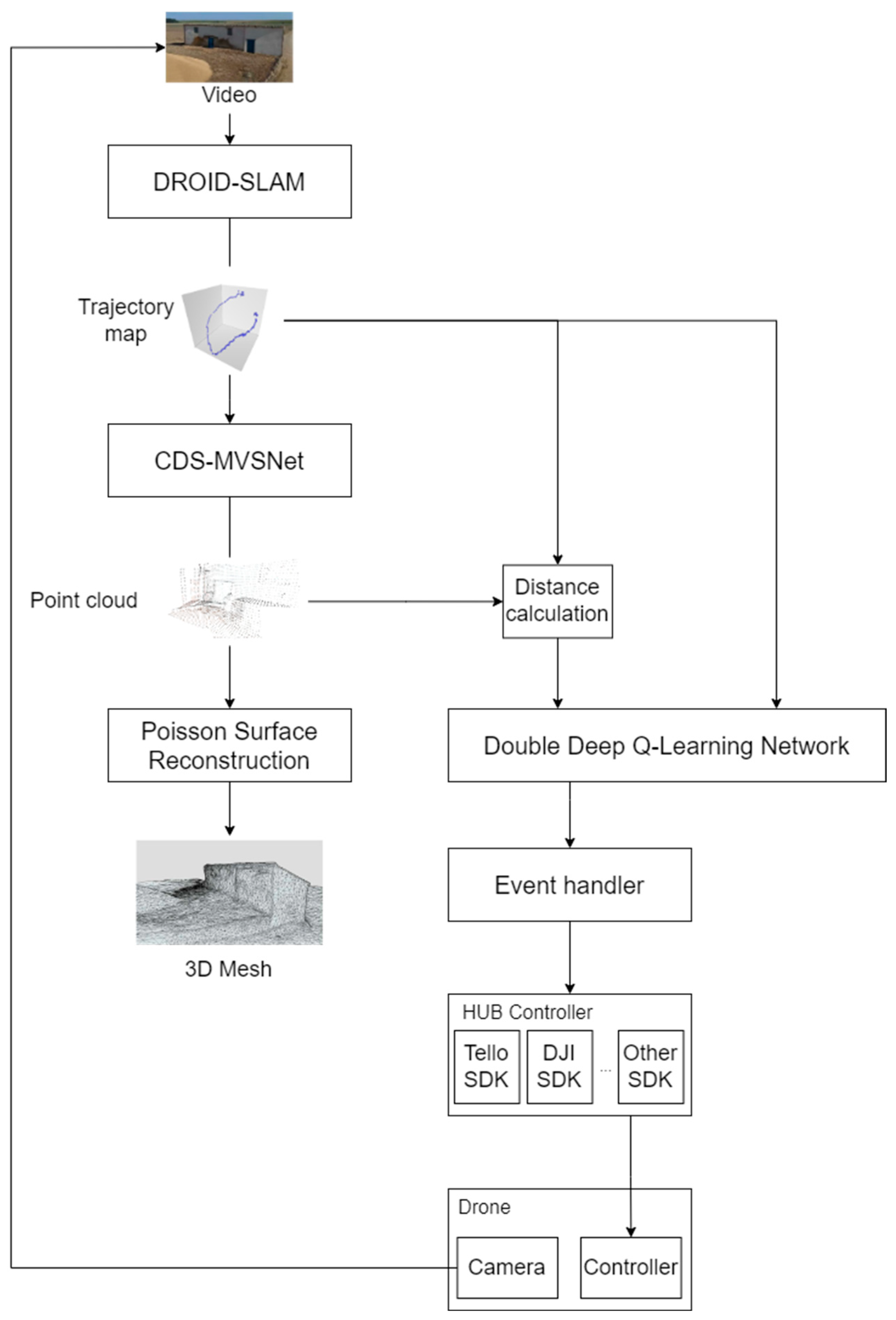
3.1. System Architecture Overview

The authors designed the system to implement the DDQN algorithm in a drone’s environment with the scope of enabling autonomous flight to generate 3D meshes. All the system components can be observed in Figure 5, which is also described below.
Figure 5. Architecture of the proposed system with its main elements. HUB. Given an input video stream, it can construct a closed mesh as output.
The system manages the continuous input of video data from the drone’s RGB camera, which is essential for creating a dynamic and up-to-date map of the environment. The system produces a 3D mesh as the final output, representing a detailed and continuous model of the environment. This mesh is created from the point cloud using the Poisson surface reconstruction algorithm.
The DROID-SLAM module performs SLAM to create a map of the environment based on the video stream. This module utilizes the video stream to construct a 4D correlation volume, which helps to understand the spatial relationships between the captured images. The system performs iterative updates of the camera positions and depth maps using a 3D correlation volume adjustment (DVA) [15].
The CDS-MVSNet module processes the environment map and video stream to generate a point cloud. The point cloud represents the 3D structure of the recorded environment. This module employs a multi-view stereoscopy (MVS) approach to reconstruct 3D scenes by calculating the depth of each point in the environment based on images captured from different angles [15].
The distance computation model calculates the distance between the drone’s current location and each point on the surface generated by the module. For the Q-learning model, the system will retain only the shortest distance. More details on this component will be provided later in Section 3.2.4.
DDQN learning is an AI model that uses reinforcement learning to optimize a drone’s flight path based on the data received from the environment. This model interacts with the drone’s controller to send movement commands. The model takes input from the calculated distance, the CDS-MVSNet module, and the DROID-SLAM module to decide the optimal movements for the drone and then sends these commands to the drone’s controller for execution. More details on this component will be provided later in Section 2.2.
The event handler in our system processes events generated by an RL AI model to manage and execute commands for a drone. It begins by collecting data from the drone’s sensors and cameras, which the AI model analyzes to detect remarkable events like obstacle detection or the need for image capture. Once an event is identified, the event listener triggers the corresponding handler function. The event handler then translates these high-level events into actionable commands, such as changing the drone’s flight path or capturing images, and sends these commands to the drone’s controller to execute the necessary actions. This integration enables the drone to autonomously navigate and respond to its environment effectively.
The Controller HUB functions as the drone’s SDK, designed to be modular and adaptable for any drone on the market. By separating the Controller HUB, we ensure that our system can easily integrate with different drone models, providing a flexible and standardized interface for drone operations. This modular approach simplifies the process of adding new drones to the system, allowing for seamless compatibility and ease of development across various platforms.
The Poisson surface reconstruction algorithm processes the point cloud to create a continuous 3D mesh. This algorithm uses the points to reconstruct a surface that represents the environment more coherently and is useful for visualization and subsequent analysis.

3.2. Design of the DDQN Algorithm with Prioritized Experience Replay

As outlined earlier, this study employs the DDQN algorithm with Prioritized Experience Replay due to its optimal balance of stability, accuracy, and learning efficiency. This approach allows the agent to develop effective policies in complex, high-dimensional environments. Some design decisions were made, the two most relevant being the reward design as well as the discrete action space. The reward design prioritizes collision avoidance, which enables the UAV to navigate around objects effectively, allowing it to collect the most sampling data with the shortest flight path to capture the target. A discrete action space was chosen even though PX4-type controllers (free hardware) support more complex actions, such as angular velocities of the pitch, yaw, and roll axes. The reason for using this discrete action space is portability to other simpler controllers and facilitating proof-of-concept experiments. The following subsections provide a detailed description of the algorithm’s design and all its components.

3.2.1. Environment

The training environment was simulated using Python. In this environment, a drone starts from an initial position and can move within a defined area. The drone must avoid leaving this area and prevent collisions with an object within the environment. If either event occurs, the training episode ends. The drone’s objective is to navigate around the object while maintaining a specific distance. This is achieved by utilizing a polar coordinate system centered on the closest point of the object to guide its movements.
In Figure 6, the eight scenarios used by the DDQN algorithm are presented, aiming to learn to navigate around them while maintaining a constant distance from the shapes as much as possible. The design of these perimeters and trajectories plays a key role in the learning process of the algorithm to ensure that the drone can generalize its behavior to new configurations of obstacles or spaces once training is complete.
Figure 6. Figures (ah) show the perimeters used by the Double Deep Q-Learning Network (DDQN) algorithm as training scenarios. They consist of geometric shapes that the drone must navigate around while maintaining a constant distance from their perimeters.
Each of the subplots, a–h, represents several types of geometric challenges for the drone. The trajectories range from simple shapes like horizontal and vertical rectangles to more complex figures such as inverted “L,” “U,” and “T” shapes. Also included are some concave and convex shapes with angles other than 90/270°, such as those in Figure 6h.
The diversity in the shape and arrangement of these perimeters is crucial for the model to learn not only to navigate around specific geometric figures but also to recognize general patterns for moving around an obstacle, regardless of its orientation or geometry. The use of these trajectories allows the drone to be trained in a varied state space, increasing the algorithm’s ability to abstract general rules about movement. By including perimeters with different angles, the drone learns to manage direction transitions and “corner” situations, where decisions must be made with greater precision to avoid collisions and maintain a safe distance. Similarly, simpler rectangular perimeters (Figure 6c,d) allow the model to refine its ability to navigate along prolonged and linear trajectories, which can also be encountered in real-world environments. A key advantage of this approach is the generalization capability it provides for the drone.

3.2.2. DDQN Agent

The agent controlling the drone is based on a DDQN model with Prioritized Experience Replay. This approach allows the agent to prioritize the most significant experiences during the learning process, thereby improving its efficiency. The agent’s action space is discrete, enabling it to modify its polar coordinates centered on the point of the object closest to the drone to adjust its trajectory based on the distance to the object and the error concerning the desired distance. Throughout the process, the drone continuously recalculates its position in polar coordinates, acts, and converts these to Cartesian coordinates to update its movement and position in the environment.
The Double Deep Q-Network (DDQN) employs a neural network with a sequential architecture designed to approximate Q values. The network begins with a dense layer containing 32 units and a ReLU activation function to process the input state, followed by a batch normalization layer to normalize activations. Next, it includes a dense layer with 64 units and ReLU activation, followed by another batch normalization layer. A third dense layer with 128 units and ReLU activation is added, complemented by a dropout layer with a rate of 0.2 to mitigate overfitting. Finally, the output layer is a dense layer with a number of units equal to the action size, using a linear activation function to predict Q values for each possible action. The network is trained using the Mean Squared Error (MSE) loss function and the Adam optimizer with a specified learning rate. Table 1 shows the DDQN agent configuration parameters.
Table 1. DDQN Agent parameters.

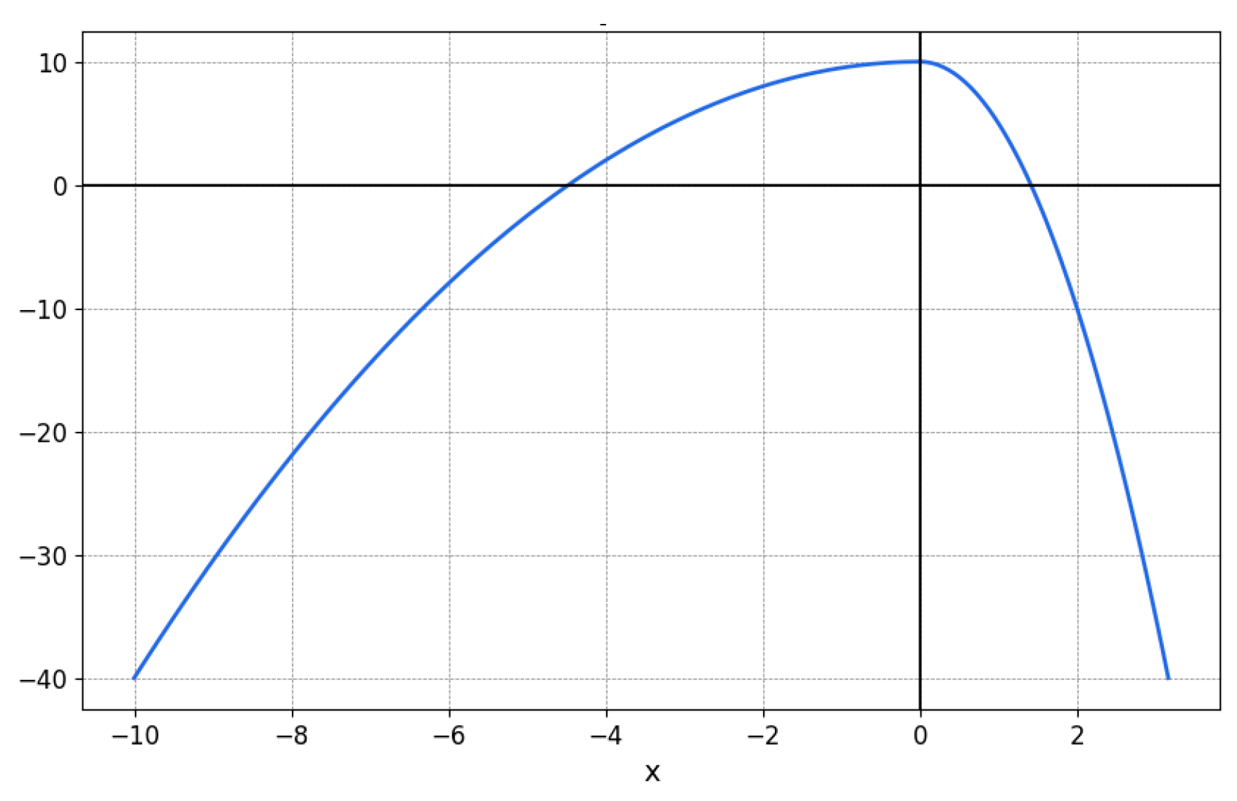
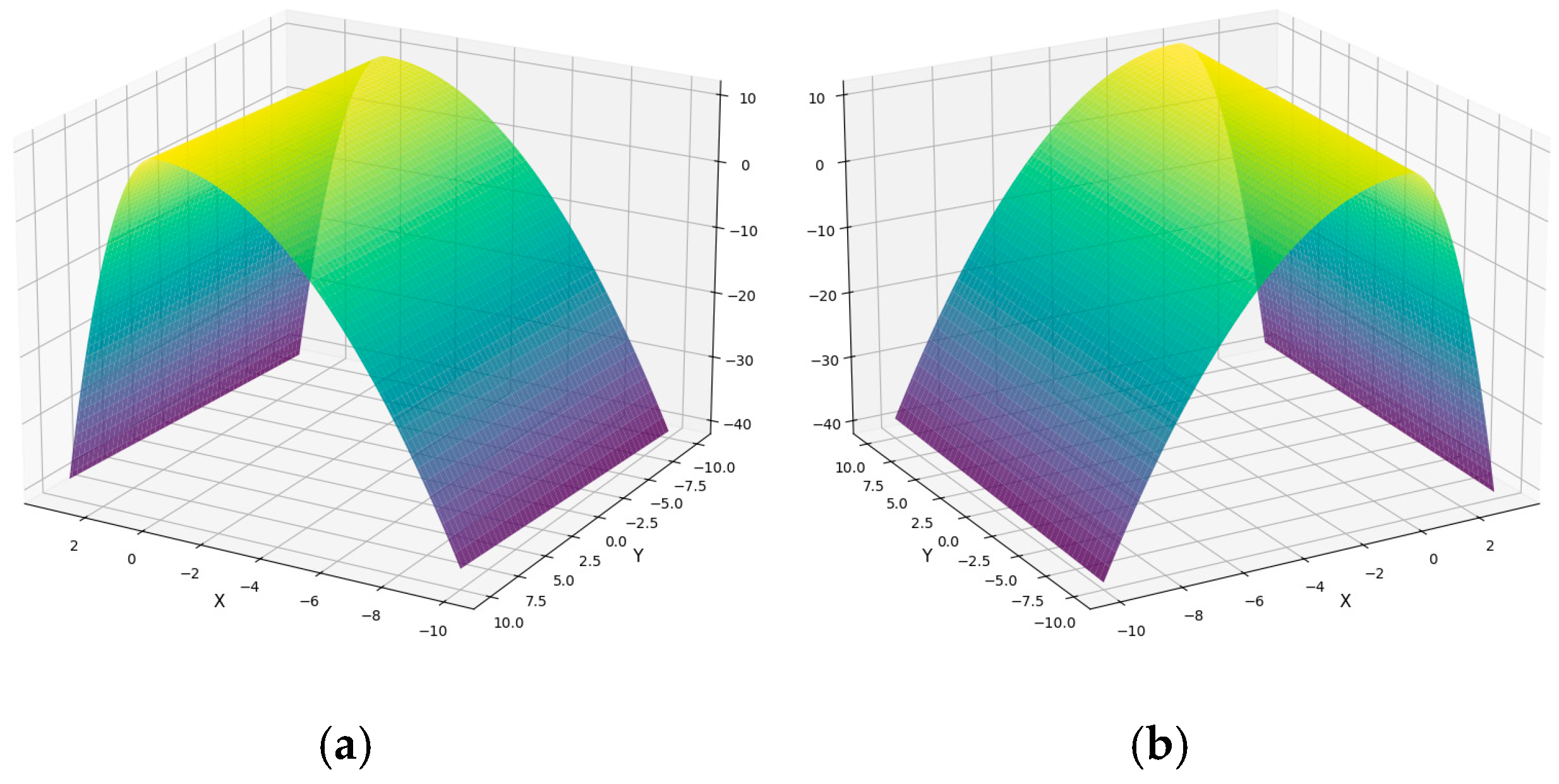
3.2.3. Reward Function

The reward function is designed to encourage behavior that maintains the desired distance from the object while penalizing undesirable situations such as collisions or leaving the allowed area. Additionally, the drone is incentivized to make efficient movements. The penalties and rewards are calibrated so that the agent learns to maintain the optimal distance, with additional incentives related to the distance traveled at each step of the episode. This reward and penalty structure allows for stable and efficient learning, enhancing the agent’s ability to achieve its goal. Being between the desired distance and the object incurs a heavier penalty than being further away from the desired distance.
Let d be the distance to the object at a given moment and d w the desired distance. The error is defined as x = d w d . Let y be the distance traveled in a step. Let “done” be a Boolean variable indicating whether the episode has ended, meaning that the drone has gone out of bounds or collided with the object. Thus, the reward function is defined as follows:
r = 0.1 y 100 ,     i f   d o n e = 1   0.5 x 2 + 0.1 y + 10 ,     i f   x < 0 5 x 2 + 0.1 y + 10 ,     i f   x 0
The constant factors in the reward function were determined experimentally and empirically to ensure the function met several specific objectives. First, the aim is to penalize it more significantly when the agent is between the object and the desired distance x 0 compared to when it is outside this zone x < 0 , which is why the coefficient for x 2 is larger in magnitude ( 5 versus 0.5 ). Additionally, the constant term + 10 was chosen to facilitate the interpretability of the accumulated reward per episode, as it allows its maximum to be approximately proportional to the product of the number of steps by ten. Finally, the term proportional to y encourages the agent to move around the object without being overly dominant, thanks to the moderate coefficient of 0.1 .
In Figure 7, the reward function can be visualized in relation to the variable x omitting the episode termination case. In Figure 8, the reward function can be visualized concerning both variables, also omitting the episode termination case.
Figure 7. Reward function r with respect to the variable x .
Figure 8. Two different views of the reward function r in 3D. Warm colors represent higher and positive rewards while cooler colors represent lower and even negative values. (a) View 1. (b) View 2.

3.2.4. Point Cloud Distance Calculation Model

The proposed algorithm calculates the average distance between a reference point and its nearest neighboring points within a three-dimensional point cloud. Given point p and a point cloud C :
p 3 ,     C = c 1 , c 2 , ,   c N 3
the goal is to find the k nearest points to p in C and compute the average distance to those neighbors. To achieve this, a k-d tree (KD Tree) is first constructed using the point cloud C , allowing for efficient searching of the nearest neighbor points. By querying the tree, the indices of the k closest points are identified with k = 30 :
c i 1 , c i 2 , ,   c i k ,     k = 30
Now, the interquartile range (IQR) method is applied to the set of nearest points to remove potential outliers that do not belong to the object.
Let us define the following:
-
Q 1 is the first quartile (25th percentile) of the dataset.
-
Q 3 is the third quartile (75th percentile) of the dataset.
-
I Q R = Q 3 Q 1 represents the interquartile range.
-
L o w e r   B o u n d = Q 1 1.5   ×   I Q R .
-
U p p e r   B o u n d = Q 3 + 1.5   ×   I Q R .
Any point outside these bounds is considered an outlier and will be removed from Ysthe dataset.
Let k be the number of points in the set of nearest points after the cleaning process and c i 1 , c i 2 , ,   c i k the set of nearest points after the cleaning process. Then, the corresponding Euclidean distances are calculated as:
d j = p c i j 2 ,     j = 1 , 2 , ,   k
where · 2 denotes the Euclidean norm. Finally, the average distance is computed:
d ¯ = 1 k j = 1 k d j ,
which is the value returned by the algorithm. This approach is computationally efficient due to the structure of the KD Tree, allowing for fast searching even in large point clouds.

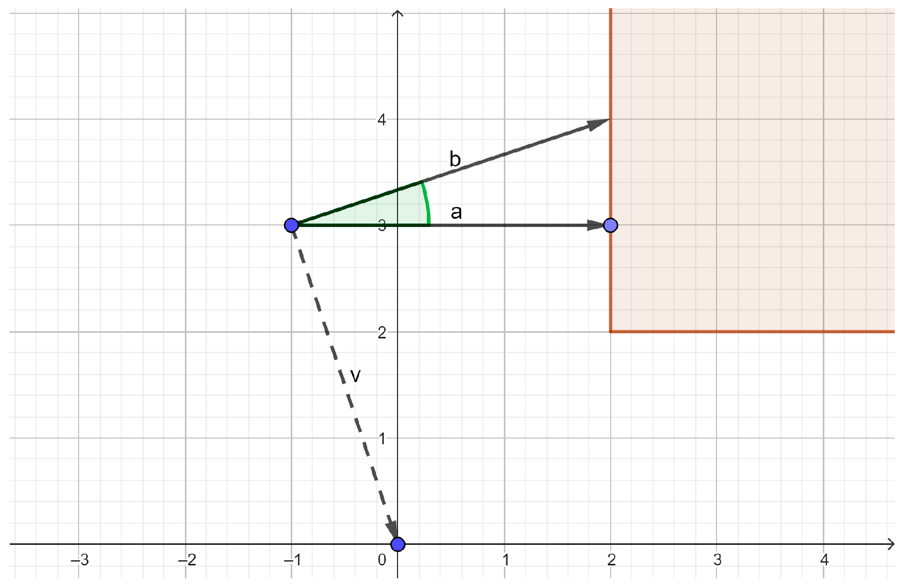
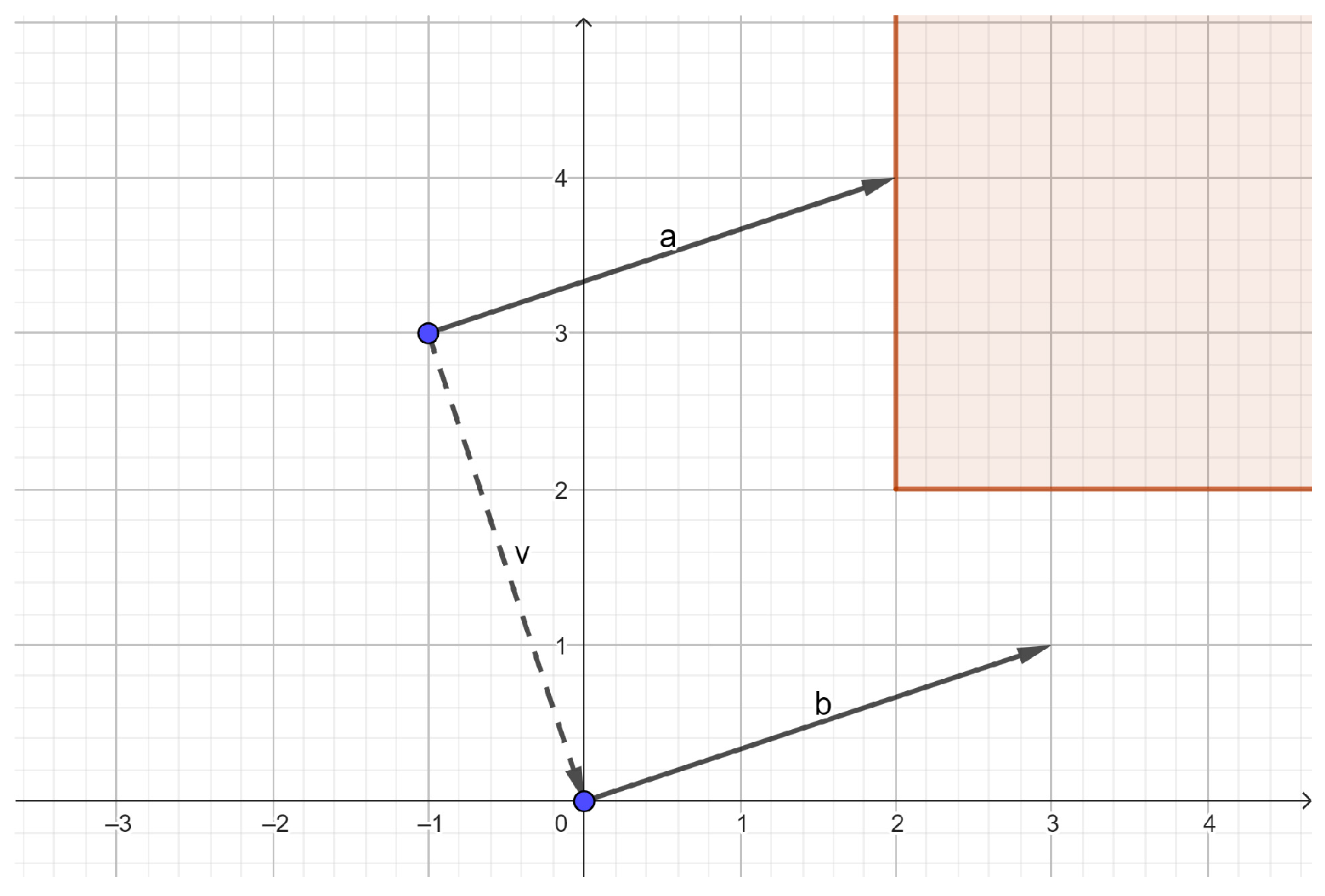
3.2.5. Flight Instructions

To correctly generate the commands that “translate” the movement in polar coordinates to a movement that the drone can perform while being oriented toward the object for precise movement, two key steps were implemented, as developed in the following paragraphs: (1) rotation about the Z-axis and (2) movement toward the desired position. This method ensures that the drone first orients itself in the necessary direction to subsequently move laterally (to the right) to the correct position, always keeping focus on the object. It is assumed that the drone starts aligned with the object.
Rotation About the Z-Axis
The angle of rotation necessary to turn the drone in the right direction, either clockwise or counterclockwise, must be determined. This process begins by identifying the vector that connects the drone’s current position with the position it wants to reach, called vector v = a , b . Then, a perpendicular vector to this is calculated; if v is a , b , the perpendicular vectors are b , a and b , a . Next, the drone’s current Z-rotation, α 1 , is compared with the Z-rotation of the perpendicular vector α 2 . The angle necessary to turn the drone toward the new direction, α 3 , is calculated as α 3 = α 2 α 1 . If α 3 is negative ( α 3 0 ), the drone must turn clockwise, and the generated command will be ‘cw α 3 ’. If α 3 is positive ( α 3 > 0 ), the turn must be counterclockwise, and the command will be ‘ccw α 3 ’. This process can be graphically visualized in Figure 9.
Figure 9. Step 1 begins with the orientation of vector a, that is, oriented toward the closest object to the drone (red perimeter). A perpendicular vector to v, b is calculated. Finally, the rotation from a to b is made, i.e., the green angle.
Movement Toward the Desired Position
Finally, the distance the drone must travel in the direction of vector v is calculated, which is always to the right of the object, as the drone has learned to move. This command is expressed as ‘right v ’ or ‘right a 2 + b 2 ’. This process can be graphically visualized in Figure 10.
Figure 10. Step 2, where after rotating, the drone advances to the right, from vector a to vector b, the size of vector v.

3.2.6. Training and Flight Algorithm

The training algorithm is described in Algorithm 1:
Algorithm 1: Double Deep Q-Learning Network with Prioritized Experience Replay training Algorithm
  Initialize replay memory D to capacity N .
  Initialize prioritized sampling mechanism D to capacity N .
  Initialize action-value functions Q and Q with random weights θ and θ .
  Initialize target network Q with weights θ θ .
  Initialize the environment.
  for episode = 1 , ,   M  do
    Initialize randomly the desired distance d e p i s o d e in the defined range.
    Choose a random scenario from the set of scenarios.
    Reset the environment with the chosen scenario.
    Initialize the state to s 1 .
    for t = 1 , ,   T  do
      With probability ϵ select a random action a t .
      Otherwise select a t = m a x a   Q s t , a ; θ .
      Execute action a t in the environment and observe reward r t and next state s t + 1 .
      Store the transition s t , a t , r t , s t + 1 in D assigning a maximum priority.
      Set s t = s t + 1 .
      Sample a minibatch of transitions s t , a t , r t , s t + 1 from D using prioritized sampling.
      for each sampled transition j  do
        Set y j = r j ,                                                                                                         f o r   t e r m i n a l   s j + 1 r j + γ Q s j + 1 , m a x a   Q s j + 1 , a ; θ ; θ ,     f o r   n o n t e r m i n a l   s j + 1
        Update the priority of the transition j in D based on the updated TD-error.
      end for
      Perform a gradient descent step on the loss function
      y j Q s j + 1 , a j ; θ 2 .
      Set ϵ = ϵ · δ , where δ is the exploration decay parameter.
      Update the target network Q using the soft update mechanism, defined by:
       θ τ θ + 1 τ θ .
    end for
  end for
The flight algorithm, which makes all decisions by applying the previously discussed techniques, is described in Algorithm 2.
Algorithm 2: Flight loop
  Load the weights θ of the trained model in a new agent.
  Initialize the environment.
  Initialize the desired distance d e p i s o d e in the defined range.
  Reset the environment with the flight scenario.
  Initialize the state to s 1 .
  Save the initial position p 1 = x 1 ,   y 1 and the initial Z-rotation, ϕ 1 = 0 º .
  for t = 1 , ,   T do
    Select an action a t = m a x a   Q s t , a ; θ given by the trained agent.
    Execute action a t in polar coordinates.
    Save the desired position p 2 = x 2 ,   y 2 .
    Generate the movement command from p 1 to p 2 .
    Generate the rotation command to refocus on the object.
    Observe reward r t and next state s t + 1 .
    Set s t = s t + 1 .
  end for

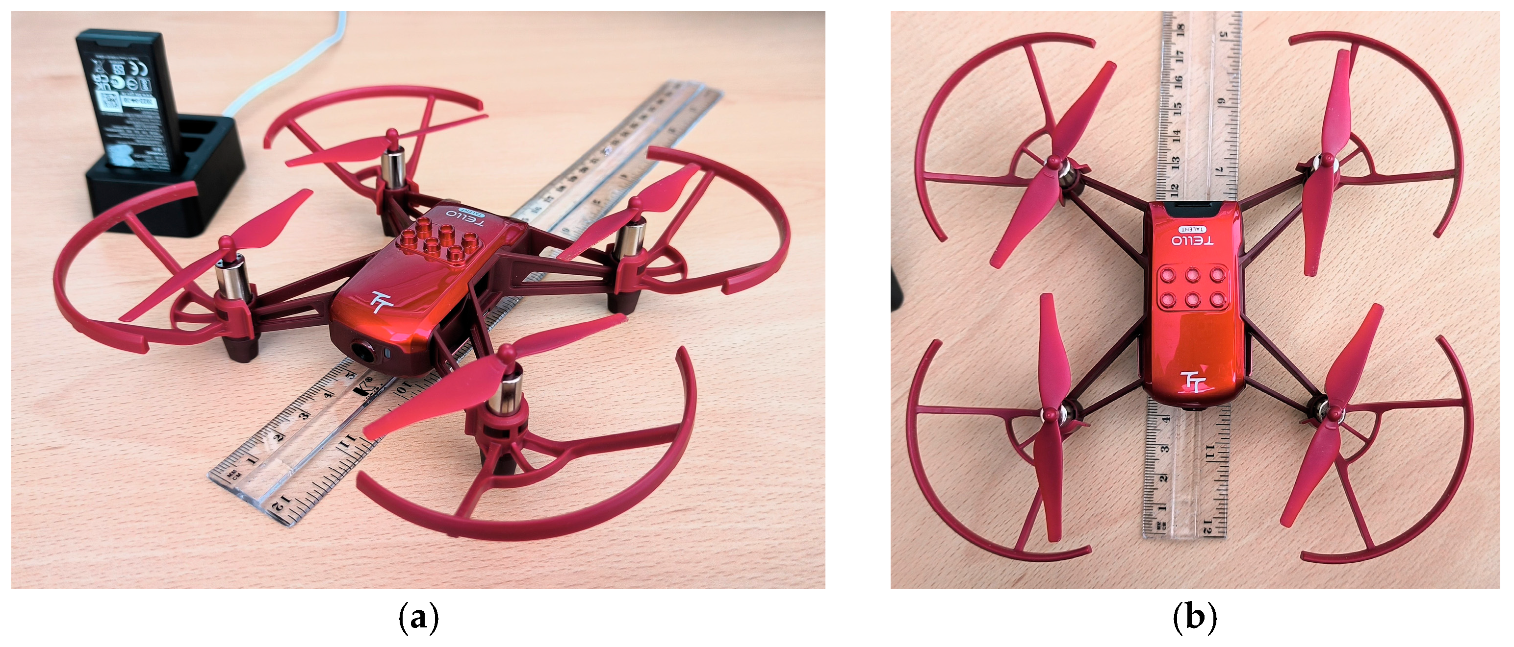
3.3. Drone and Workstation

The drone used in the experiments is a Tello Robomaster TT, a small quadcopter drone (measures 18 × 5 × 18 cm. with guards and weight 135 g.) developed by DJI for educational purposes. This open-source drone supports software scalability via its SDK and hardware scalability through I2C (inter-integrated circuits), SPI (Serial Peripheral Interface), UART (Universal Asynchronous Receiver–Transmitter), and GPIO (General Purpose Input/Output) interfaces. It features a 5 MP HD camera installed in the nose, sensors like time-of-flight, a barometer, an IMU (Inertial Measurement Unit), brushless motors, and a lithium-ion battery providing up to 10 min of flight time. Figure 11 shows two views of the aircraft.
Figure 11. (a) Overview and (b) zenithal view of the mini drone DJI Tello Robomaster TT with its battery charger and a visual size reference.
The autonomous drone includes a camera and a controller. The camera captures real-time video streams and images of the environment. This video stream is crucial for SLAM processes. The camera sends the video stream to the “AI Models” for further processing. This video stream is used by the DROID-SLAM module to generate an environmental map. The drone’s controller is responsible for the drone’s stability and control. This component ensures that the drone maintains its position, manages environmental disturbances such as wind, and follows the flight path according to the instructions from the Q-learning algorithm received via radio from the “Controller Hub”. Other aircraft could be used if they are equipped with a programmable SDK and an RGB camera.
A land-based workstation (can be a laptop) with a dedicated graphics card as well as a reasonable amount of RAM and processor is required. The specifications of the workstation computer used in the experiments are shown in Table 2.
Table 2. Specifications of the computer used in the prototype.

4. Results

The presentation of the results is divided into three parts, according to the sub-subjects of the project. All the results were obtained with the hardware described in Table 2, which contains the specifications of the computer used for the training and executions of the prototype.

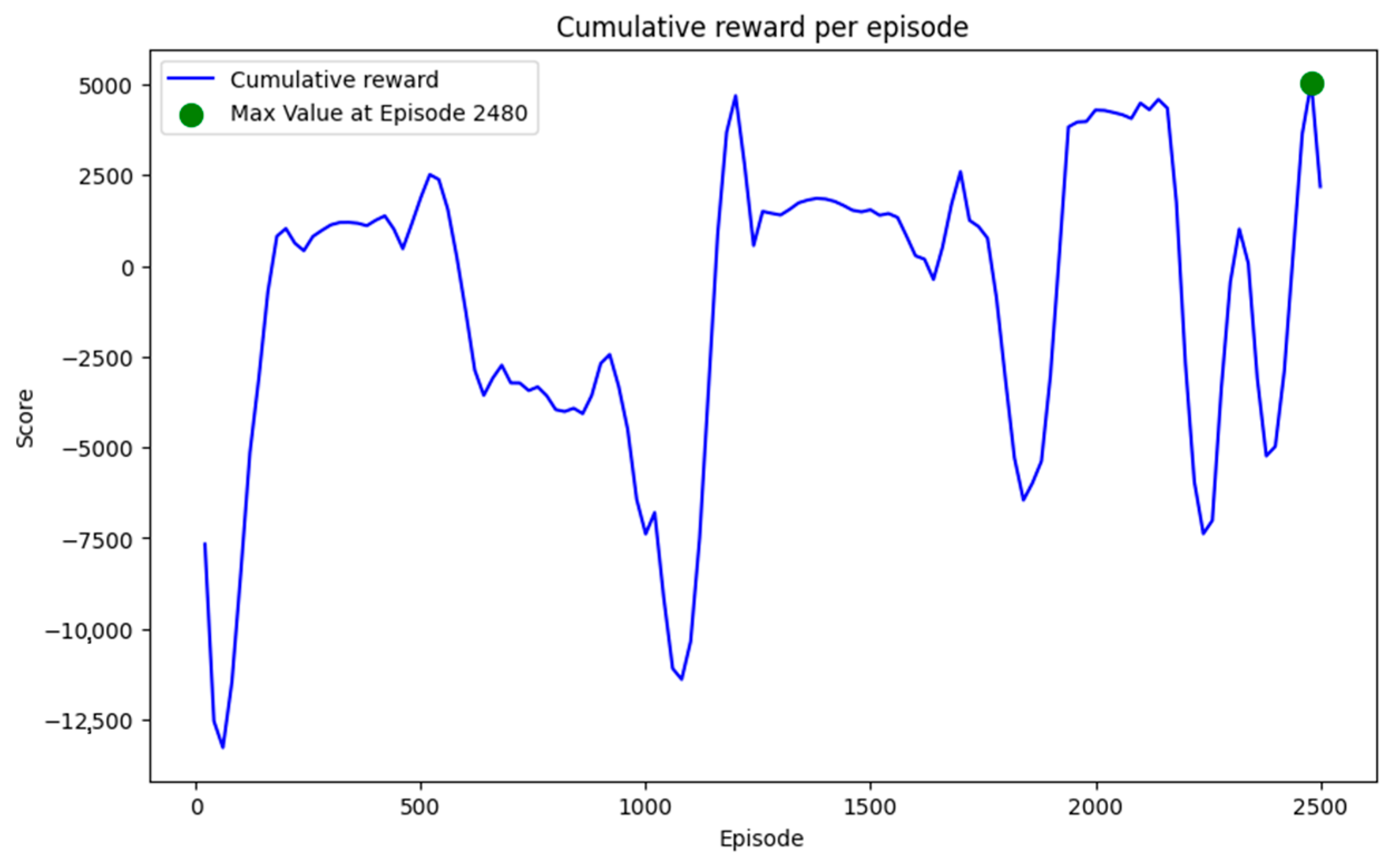
4.1. Training of the DDQN Model

The presented model was obtained through training over 2500 episodes, each with a maximum limit of 500 movements, taking nearly 10 h to execute in the hardware described in Table 2. More specifically, the developed model is the one that achieved the best performance in the accumulated episode reward. This was obtained in episode 2480, as shown in Figure 12. During training, the model faced eight different scenarios represented by eight distinct 2D geometric shapes (see Figure 6). In each episode, a different figure was randomly selected so that the model could learn to maneuver around various shapes. This approach allowed the agent to generalize its behavior and improve its ability to handle different situations in the environment. Figure 12 shows the evolution of the rewards over the episodes, with the maximum possible value for an execution being approximately 5000. Once training was completed, a model capable of adequate generalization for the present problem was obtained.
Figure 12. Graph of reward evolution during training with an upward trending moving average. The maximum Score, obtained in epoch 2480, highlights the best model that the algorithm is capable of learning in 2500 epochs.
In reinforcement learning (RL), traditional metrics such as accuracy and loss are not directly applicable. Instead, the performance of the model is evaluated based on the cumulative reward achieved during training. In our case, the maximum reward obtained during training was approximately 5000, as depicted in Figure 12. This reflects the model’s ability to generalize and execute optimal trajectories in diverse scenarios. To provide a clear overview of the training setup and parameters used for the development of the DDQN model, Table 3 summarizes the key aspects of the training configuration. These parameters were chosen to balance computational efficiency and model performance, ensuring the agent’s ability to learn effective navigation policies in a variety of scenarios.
Table 3. Training parameters and key metrics for the DDQN model, including the action space, reward function, and performance indicators.

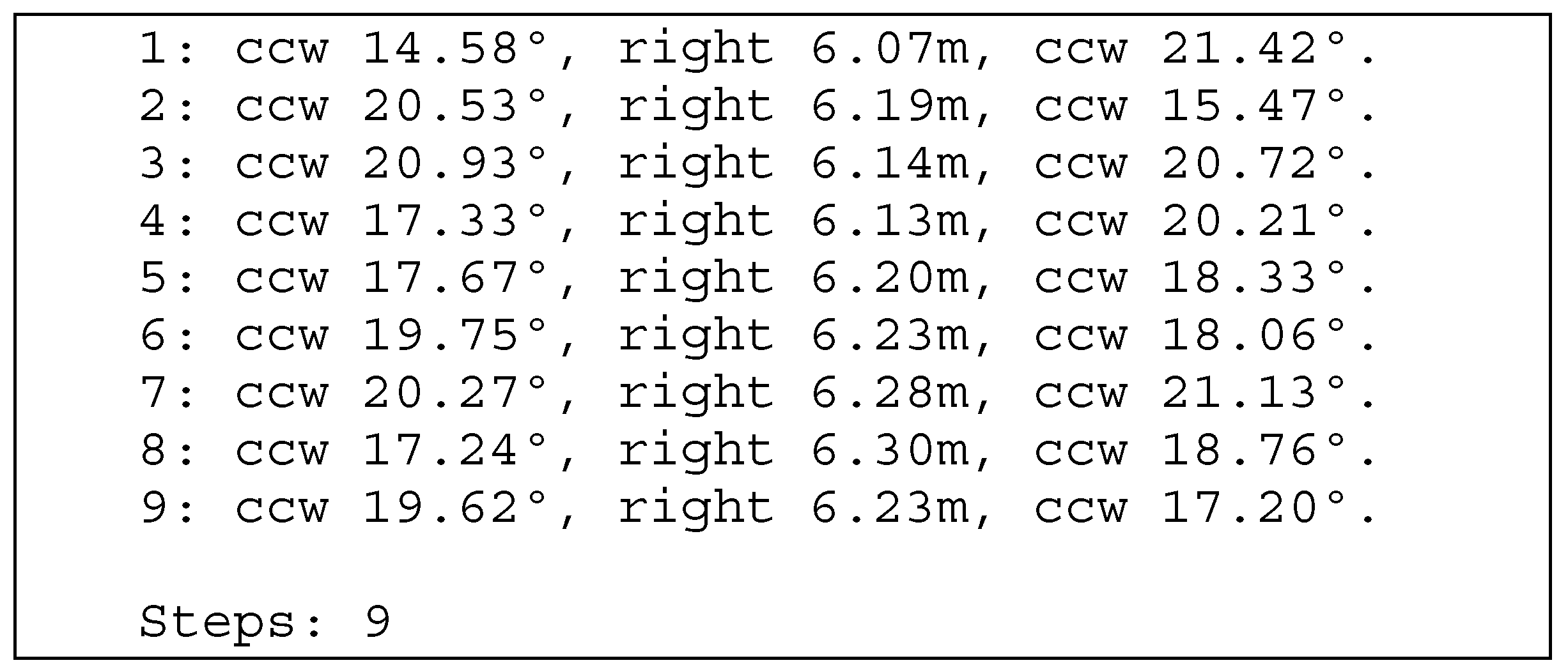
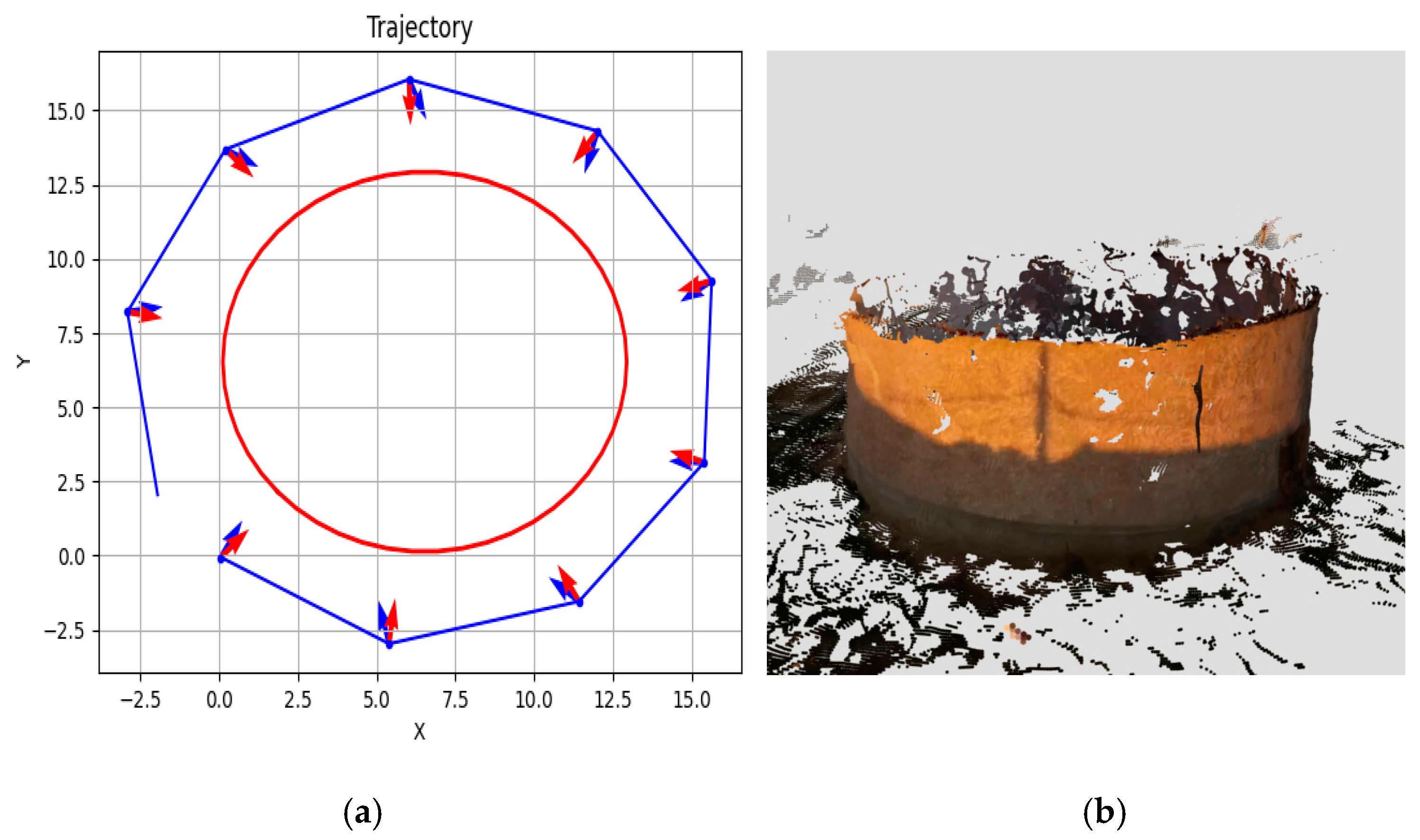
4.2. Generation of Flight Instructions

Regarding the integration of the different subsystems, navigation was validated through the generation of directly executable instructions or commands for the drone. These were created according to the format accepted by the SDK of the device used in the experiments, the Tello Robomaster. In Figure 13, the sequence of commands is presented and organized into waypoints (steps). For each step, a rotation (left or right), a movement to the right, and a second rotation are generated. This is performed to circle the point of interest (POI) while maintaining the camera’s orientation toward that object, following its perimeter. Table 4 shows some of the commands from the SDK used in the experiments. These commands are the ones displayed in the output captured in Figure 13.
Figure 13. Generated instructions for capturing a cylindrical-shaped building.
Table 4. Command subset used in the experiments from Robomaster TT SDK3.0 [48].
In Figure 14a, the drone’s movement around the object can be observed, starting from the bottom left corner (near the origin of coordinates) and moving counterclockwise. At each step, it orients itself to reach the destination point, moves to the right, focuses on the nearest point (POI), and then starts the cycle again. This allows the drone to encircle the object without losing sight of it. The steps and instructions described in Figure 13 can be seen in Figure 14a, where the blue line represents the path taken, each red vector indicates the drone’s orientation toward the object before each movement, and each blue vector shows the orientation the drone should take for each movement to then move to the right and reach the desired position. The perimeter of the object that can be seen as the red line in Figure 14a is generated as the distance calculation algorithm is applied to the points generated in the point cloud shown in Figure 14b.
Figure 14. (a) Drone movement around the building (perimeter in red), with its movements (blue line) and orientation corrections (blue and red arrows). (b) Point cloud generated during the flight.
In this specific execution of the DDQN model, the UAV completed its trajectory in nine steps, achieving a cumulative reward of 90.0789. This result is consistent with the structure of the reward function, where the term for x is approximately zero at each step. Consequently, the reward closely matches the product of the number of steps and the constant term in the reward function ( 9   ×   10 ). The observed value of 90.0789 reflects the UAV’s efficient adherence to the desired trajectory while maintaining the required distance d w from the object. The slight deviation above 90 arises from the combined effect of the distance traveled ( y ) and the minimal penalties introduced by the quadratic term ( 0.5 x 2 or 5 x 2 ) based on the error x = d w d . Since the UAV avoided collisions and stayed within bounds, no termination penalties ( 100 ) were applied, allowing the reward to remain near its theoretical maximum. This result underscores the model’s ability to execute near-optimal trajectories under the designed reward structure, achieving a high cumulative reward over a short episode.

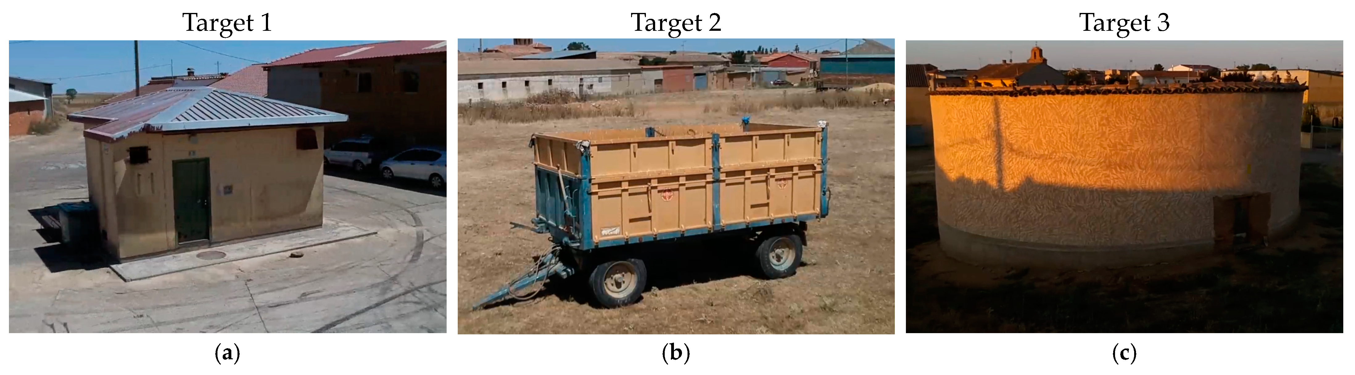
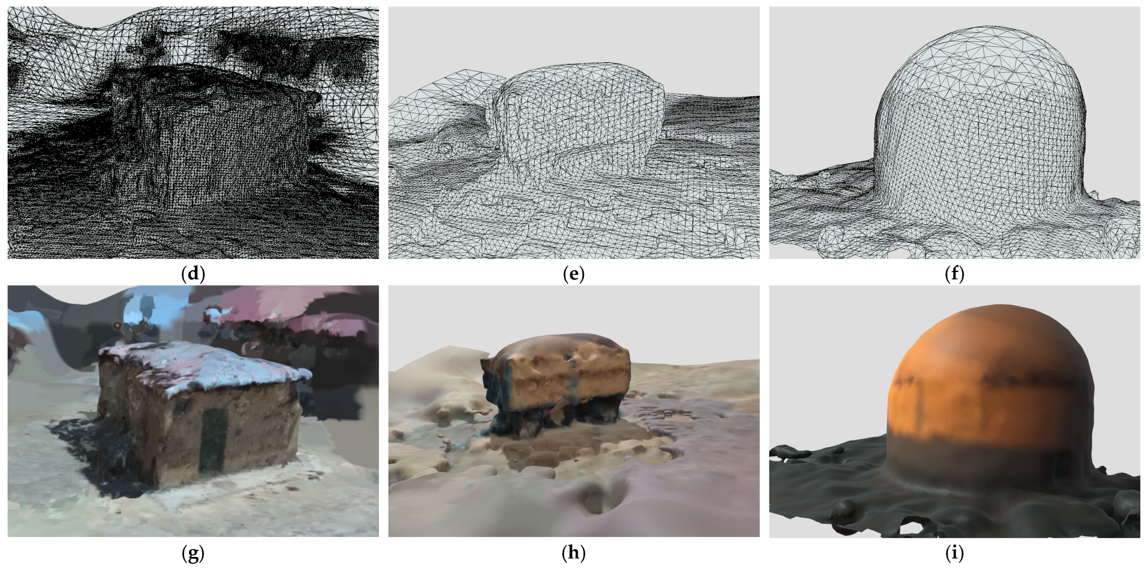
4.3. Automatic Generation of 3D Meshes

In the presented results, three examples of 3D reconstructions using the autonomous drone navigation system developed in this work are shown. The system could reconstruct these three different structures: a shed (Target 1), a trailer (Target 2), and a dovecote (Target 3), using images captured by the monocular RGB camera of the Tello Robomaster TT drone used in the experiments, as shown in Figure 15.
Figure 15. Three examples of 3D reconstructions using the system presented in this work for different structures are shown. These structures are the targets 1–3 (shed, trailer, and dovecote), sorted by columns. Images (ac) display frames from the actual video of the three targets. Images (df) show the resulting 3D mesh reconstruction of each target. Images (gi) present the final textured 3D reconstruction of the three targets.
Figure 15a–c display frames extracted from the actual videos of the three targets during the drone’s flights. Based on these images, the system employed the DDQN algorithm to learn how to fly around the structures and capture the necessary information to generate the 3D reconstructions. Figure 15d–f illustrate the initial meshes generated during the reconstruction process, while Figure 15g–i present the final texturized 3D reconstructions.
It is important to highlight the case of Target 3 (dovecote), where a significant limitation was observed. Due to the lack of information about the interior of the cylinder that makes up the dovecote, the 3D reconstruction carried out using the Poisson surface reconstruction algorithm failed to generate an adequate mesh, resulting in an incorrect representation of the structure, specifically the “dome” built on top of the cylinder. Regarding Target 3, Figure 14a shows the navigation decisions made and the point cloud Figure 14b that motivated these decisions by the RL algorithm. The specific instructions that were sent to the drone in the form of commands are presented in Figure 13.

5. Discussion

The autonomous drone navigation system based on the DDQN developed in this study has demonstrated a remarkable generalization capability in creating closed and complete three-dimensional meshes. This characteristic is essential for its application in various scenarios and conditions, significantly expanding its practical utility in large-scale mapping [49] and 3D modeling of objects, buildings, and large outdoor scenes.

5.1. Automation and Efficiency

One of the main advantages of the proposed approach is the ability to obtain 3D meshes in real-time and autonomously, overcoming the limitations of existing photogrammetry tools on the market. While current solutions require manual flight planning and post-capture processing, our system operates entirely automatically. This automation not only saves time and resources but also allows dynamic adaptation to the target and environmental conditions. The autonomous process ensures that the video captured during the drone’s flight possesses the necessary quality for subsequent high-resolution 3D mesh generation. By using reference tools like Meshroom in post-processing, high-quality 3D models can be obtained, fully leveraging the data collected during the drone’s autonomous flight.

5.2. Training Optimization

The number of training epochs used in our DDQN model has proven to be adequate for the complexity of the problem addressed. Although some degree of overfitting was initially suspected towards the end of training, subsequent evaluations demonstrated that the model retained its ability to generalize effectively to unseen scenarios. For instance, while the training set included geometric shapes such as rectangles and trapezoids, the model was successfully tested with significantly different shapes, such as circles as a dovecote (Target 3 in Figure 15) and irregular forms (e.g., an “E”-shaped perimeter). This confirms that the model does not rely solely on the specific configurations seen during training.
This phenomenon is manifested in the drone’s ability to “lock onto” the object by centering the polar coordinates on the closest approximated point, efficiently enveloping the target during its autonomous flight to capture all necessary angles and details [50].
During training, the DDQN algorithm optimizes the action policy to avoid overfitting to a specific set of shapes. The use of Prioritized Experience Replay (PER) maintained diversity in the sampled experiences and validated the model with a separate test dataset. Additionally, the robustness of the trained DDQN algorithm was evaluated through its performance on new geometric shapes not encountered during training, where it successfully adapted and efficiently enveloped the targets. This generalization capability is crucial for any application of reinforcement learning in robotics or autonomous navigation.
A real environment can rarely be defined by simple and predictable shapes; obstacles and paths are dynamic and vary in complexity. Therefore, the drone’s ability to extrapolate what it learned in these artificial trajectories to a more varied context is what makes it useful in practical applications, such as infrastructure inspection, package delivery in urban areas, or exploration of unknown environments.

5.3. Autonomous Decision-Making

The relevance of this work using a DDQN [51] is reflected in its ability to adapt to the specific needs of autonomous navigation for 3D model creation. While the scope of this study is limited to three objects of similar characteristics, the results demonstrate that the learned policies enable the drone to efficiently navigate around perimeters and create detailed 3D models in a fully autonomous manner. This behavior is particularly promising for applications requiring resource optimization, such as managing limited battery life and operating in dynamic environments.
The success of this strategy suggests that using varied trajectories, combined with deep learning based on reward and punishment feedback, is a suitable approach for enhancing the generalization capability of autonomous agents. The proposed system demonstrates a unique ability to autonomously decide the path and framing to follow in capturing all angles and details of the target. This real-time decision-making ability based on the region to be modeled and the tolerable assumptions represents a significant advancement in the field of photogrammetry and 3D modeling assisted by drones.

5.4. Practical Applications

The system’s versatility makes it particularly valuable for a wide range of applications, including precision surveying, archaeological documentation, infrastructure inspection, urban planning, and cultural heritage conservation, among others. In all these fields, the system’s ability to autonomously create complete and accurate 3D models can lead to significant improvements in the efficiency, accuracy, and safety of mapping and modeling operations [52].

5.5. Limitations

Using an indoor drone like the Tello Robomaster TT is a significant limitation, despite its advantages in terms of SDK and ease of development. For creating closed and complete 3D meshes of large outdoor objects, more specialized drones are required. The main limitations of the device include its limited range and autonomy, short flight time, and restricted coverage, making it unsuitable for capturing large objects or extensive scenes. Additionally, the lack of GPS and advanced sensors impedes precise navigation in outdoor environments, while the low resolution and limited control of the camera affect the quality of photogrammetry images.
Moreover, this drone is not designed to operate under varying weather conditions, such as wind or low light.
Another significant limitation is the lack of detailed real-world testing in complex and uncontrolled outdoor scenarios. Factors such as varying lighting, weather conditions, and dynamic obstacles have yet to be fully explored.

6. Conclusions and Future Work

This study presents an innovative autonomous navigation system for drones based on a DDQN for creating closed and complete three-dimensional meshes using monocular RGB cameras. The results demonstrate that the system can generate 3D models of objects, buildings, and large outdoor scenarios in a fully autonomous manner and in real time.
Our approach demonstrates significant advantages in real-time adaptability and efficiency over pre-defined flight patterns like Boustrophedon, which are commonly used but lack flexibility in dynamic environments. While alternative reinforcement learning algorithms such as PPO, DQN, and DDPG also show promise in UAV navigation, our choice of a DDQN balances sample efficiency and generalization. In terms of 3D mesh generation, our system emphasizes accessibility and cost-effectiveness compared to conventional photogrammetry tools and LiDAR-based methods, which, while more precise, require offline processing and expensive hardware.
However, the level of detail may vary depending on the complexity of the structure and the specific requirements of certain applications. The system’s ability to dynamically adapt to various environments and objectives, along with its capability to make autonomous decisions regarding the optimal path and framing, represents a significant advancement in large-scale mapping and 3D modeling.
The implementation of this system has the potential to revolutionize multiple fields, from surveying and archaeology to urban planning and cultural heritage conservation. By eliminating the need for manual flight planning and post-capture processing, the system not only increases operational efficiency but also enhances the accuracy and consistency of the resulting 3D models. Furthermore, the system’s compatibility with professional-grade multirotor drones equipped with high-resolution sensors and RTK/PPK (Real-Time Kinematic/Post-Processed Kinematic) technology ensures the versatility and applicability of the method across a wide range of scenarios.
Future developments could focus on optimizing the DDQN algorithm to further improve energy efficiency and model quality, as well as integrating collaborative mapping capabilities using multiple drones simultaneously. Future work will also include extending experiments to uncontrolled outdoor environments and testing how flight altitude and camera angles affect the quality of the generated meshes. Preliminary insights suggest that altitude must be carefully adapted to the size of the target and the desired level of detail to avoid occlusions or gaps in the 3D reconstruction.
Additionally, transitioning to an angular velocity action space is expected to yield significant improvements in control precision and overall system performance. This modification will enable smoother and more continuous flight trajectories, crucial for maintaining stability and minimizing energy consumption. Future work will involve implementing and evaluating this action space modification to quantitatively measure its impact on navigation efficiency and 3D reconstruction quality in both controlled and real-world scenarios.

Author Contributions

Conceptualization, J.S.-S., S.B.R. and. N.G.-H.; methodology, J.S-S., M.Á.R.-G. and N.G.-H.; software, M.Á.R.-G. and G.P.-P. ; validation, J.S.-S., M.Á.R.-G. and G.P.-P.; formal analysis, M.Á.R.-G., S.B.R. and N.G.-H.; investigation, J.S.-S., M.Á.R.-G., G.P.-P., S.B.R. and N.G.-H.; resources, J.S.-S., S.B.R. and N.G.-H.; data curation, M.Á.R.-G. and G.P.-P.; writing—original draft preparation, J.S.-S., M.Á.R.-G., G.P.-P. and N.G.-H.; writing—review and editing, J.S.-S., M.Á.R.-G., G.P.-P., S.B.R. and N.G.-H.; visualization, J.S.-S., M.Á.R.-G. and G.P.-P.; supervision, J.S.-S.; project administration, J.S.-S.; funding acquisition, J.S.-S. All authors have read and agreed to the published version of this manuscript.

Funding

This research and the APC were funded by Universidad Francisco de Vitoria, grant numbers UFV2023-27 “Automatic creation of closed and complete 3D meshes using drones” and UFV2024-33 “Autonomous drone navigation system for the creation of closed and complete 3D meshes”.

Data Availability Statement

Three-dimensional reconstruction models of the experiments can be found at https://sketchfab.com/3D_DDQLN (accessed on 14 October 2024).

Acknowledgments

The authors would like to thank the Universidad Francisco de Vitoria and the Universidad Europea de Madrid for their support.

Conflicts of Interest

The authors declare no conflicts of interest.

References

  1. El-Sallabi, H.; Aldosari, A.; Alkaabi, S. UAV path planning in absence of GPS signals. In Proceedings of the Unmanned Systems Technology, Anaheim, CA, USA, 9–13 April 2017; Volume 10195, pp. 386–399. [Google Scholar] [CrossRef]
  2. Zhang, Q.; Zhu, M.; Zou, L.; Li, M.; Zhang, Y. Learning Reward Function with Matching Network for Mapless Navigation. Sensors 2020, 20, 3664. [Google Scholar] [CrossRef] [PubMed]
  3. Sung, C.-K.; Segor, F. Onboard pattern recognition for autonomous UAV landing. In Proceedings of the Applications of Digital Image Processing XXXV, San Diego, CA, USA, 12–16 August 2012; Volume 8499, pp. 561–567. [Google Scholar] [CrossRef]
  4. Al Said, N.; Gorbachev, Y. An Unmanned Aerial Vehicles Navigation System on the Basis of Pattern Recognition Applications. J. Southwest Jiaotong Univ. 2020, 55, 1–9. [Google Scholar] [CrossRef]
  5. Lee, A.; Yong, S.P.; Pedrycz, W.; Watada, J. Testing a Vision-Based Autonomous Drone Navigation Model in a Forest Environment. Algorithms 2024, 17, 139. [Google Scholar] [CrossRef]
  6. Wang, Z.; Li, J.; Mahmoudian, N. Synergistic Reinforcement and Imitation Learning for Vision-driven Autonomous Flight of UAV Along River. arXiv 2024, arXiv:2401.09332v2. [Google Scholar]
  7. Wu, J.; Ye, Y.; Du, J. Multi-objective reinforcement learning for autonomous drone navigation in urban areas with wind zones. Autom. Constr. 2024, 158, 105253. [Google Scholar] [CrossRef]
  8. Wubben, J.; Fabra, F.; Calafate, C.T.; Krzeszowski, T.; Marquez-Barja, J.M.; Cano, J.C.; Manzoni, P. Accurate Landing of Unmanned Aerial Vehicles Using Ground Pattern Recognition. Electronics 2019, 8, 1532. [Google Scholar] [CrossRef]
  9. Visockiene, J.S.; Puziene, R.; Stanionis, A.; Tumeliene, E. Unmanned Aerial Vehicles for Photogrammetry: Analysis of Orthophoto Images over the Territory of Lithuania. Int. J. Aerosp. Eng. 2016, 2016, 4141037. [Google Scholar] [CrossRef]
  10. Zhao, K.; He, T.; Wu, S.; Wang, S.; Dai, B.; Yang, Q.; Lei, Y. Application research of image recognition technology based on CNN in image location of environmental monitoring UAV. EURASIP J. Image Video Process. 2018, 2018, 150. [Google Scholar] [CrossRef]
  11. Wang, X.; Cheng, P.; Liu, X.; Uzochukwu, B. Fast and Accurate, Convolutional Neural Network Based Approach for Object Detection from UAV. In Proceedings of the IECON 2018—44th Annual Conference of the IEEE Industrial Electronics Society, Washington, DC, USA, 21–23 October 2018; pp. 3171–3175. [Google Scholar] [CrossRef]
  12. Stokkeland, M.; Klausen, K.; Johansen, T.A. Autonomous visual navigation of Unmanned Aerial Vehicle for wind turbine inspection. In Proceedings of the 2015 International Conference on Unmanned Aircraft Systems, ICUAS, Denver, CO, USA, 9–12 June 2015; pp. 998–1007. [Google Scholar] [CrossRef]
  13. Choi, W.; Cha, Y.J. SDDNet: Real-Time Crack Segmentation. IEEE Trans. Ind. Electron. 2020, 67, 8016–8025. [Google Scholar] [CrossRef]
  14. Waqas, A.; Kang, D.; Cha, Y.J. Deep learning-based obstacle-avoiding autonomous UAVs with fiducial marker-based localization for structural health monitoring. Struct. Health Monit. 2024, 23, 971–990. [Google Scholar] [CrossRef]
  15. Blasco, J.C.; Rosende, S.B.; Sánchez-Soriano, J. Automatic Real-Time Creation of Three-Dimensional (3D) Representations of Objects, Buildings, or Scenarios Using Drones and Artificial Intelligence Techniques. Drones 2023, 7, 516. [Google Scholar] [CrossRef]
  16. Informe Sobre Las Actuaciones Y Medidas Emprendidas Tras La Erupción Del Volcán De Cumbre Vieja (La Palma), Seis Meses Después Del Inicio De La Emergencia. Available online: https://www.mpr.gob.es/prencom/notas/Documents/2022/060622-informe_palma.pdf (accessed on 22 October 2024).
  17. Informe de Incendios Forestales 2022 Informes DGPCE. Available online: https://www.proteccioncivil.es/documents/20121/0/INFORME%20IIFF%202022-FINAL_DICIEMBRE.pdf/a9cf0986-be76-d244-283a-4d3295309fae#:~:text=A%20lo%20largo%20de%202022,superior%20respecto%20a%20a%C3%B1os%20anteriores (accessed on 22 October 2024).
  18. DJI Terra—Digitaliza el Mundo—DJI. Available online: https://enterprise.dji.com/es/dji-terra (accessed on 24 October 2024).
  19. Jarahizadeh, S.; Salehi, B. A Comparative Analysis of UAV Photogrammetric Software Performance for Forest 3D Modeling: A Case Study Using AgiSoft Photoscan, PIX4DMapper, and DJI Terra. Sensors 2024, 24, 286. [Google Scholar] [CrossRef] [PubMed]
  20. Aliane, N.; Muñoz, C.Q.G.; Sánchez-Soriano, J. Web and MATLAB-Based Platform for UAV Flight Management and Multispectral Image Processing. Sensors 2022, 22, 4243. [Google Scholar] [CrossRef]
  21. Puertas, E.; De-Las-Heras, G.; Fernández-Andrés, J.; Sánchez-Soriano, J. Dataset: Roundabout Aerial Images for Vehicle Detection. Data 2022, 7, 47. [Google Scholar] [CrossRef]
  22. Puertas, E.; De-Las-heras, G.; Sánchez-Soriano, J.; Fernández-Andrés, J. Dataset: Variable Message Signal Annotated Images for Object Detection. Data 2022, 7, 41. [Google Scholar] [CrossRef]
  23. Rosende, S.B.; Ghisler, S.; Fernández-Andrés, J.; Sánchez-Soriano, J. Dataset: Traffic Images Captured from UAVs for Use in Training Machine Vision Algorithms for Traffic Management. Data 2022, 7, 53. [Google Scholar] [CrossRef]
  24. Rosende, S.B.; Fernandez-Andres, J.; Sanchez-Soriano, J. Optimization Algorithm to Reduce Training Time for Deep Learning Computer Vision Algorithms Using Large Image Datasets with Tiny Objects. IEEE Access 2023, 11, 104593–104605. [Google Scholar] [CrossRef]
  25. Rosende, S.B.; Ghisler, S.; Fernández-Andrés, J.; Sánchez-Soriano, J. Implementation of an Edge-Computing Vision System on Reduced-Board Computers Embedded in UAVs for Intelligent Traffic Management. Drones 2023, 7, 682. [Google Scholar] [CrossRef]
  26. Yamauchi, B. Frontier-based approach for autonomous exploration. In Proceedings of the IEEE International Symposium on Computational Intelligence in Robotics and Automation, CIRA, Monterey, CA, USA, 11 June 1997; pp. 146–151. [Google Scholar] [CrossRef]
  27. Zhong, P.; Chen, B.; Lu, S.; Meng, X.; Liang, Y. Information-Driven Fast Marching Autonomous Exploration with Aerial Robots. IEEE Robot. Autom. Lett. 2022, 7, 810–817. [Google Scholar] [CrossRef]
  28. Cao, Z.; Du, Z.; Yang, J. Topological Map-Based Autonomous Exploration in Large-Scale Scenes for Unmanned Vehicles. Drones 2024, 8, 124. [Google Scholar] [CrossRef]
  29. Khan, S.S.; Lad, S.S.; Singh, A.M. Exploring the Use of Deep Reinforcement Learning for Autonomous Navigation in Unstructured Environments. Int. J. Res. Appl. Sci. Eng. Technol. 2024, 12, 548–558. [Google Scholar] [CrossRef]
  30. Zhang, S.; Liu, C.; Haala, N. Guided by model quality: UAV path planning for complete and precise 3D reconstruction of complex buildings. Int. J. Appl. Earth Obs. Geoinf. 2024, 127, 103667. [Google Scholar] [CrossRef]
  31. Kesack, R. Processing in Progress: A Benchmark Analysis of Photogrammetry Applications for Digital Architectural Documentation. Technol. Archit. Des. 2022, 6, 118–122. [Google Scholar] [CrossRef]
  32. COLMAP 3.11.0.dev0. Documentation. Available online: https://colmap.github.io/index.html (accessed on 22 October 2024).
  33. Photogrammetry Software: Top Choices for All Levels. 3Dnatives. Available online: https://www.3dnatives.com/en/photogrammetry-software-190920194/ (accessed on 22 October 2024).
  34. YouTube. (106) ContextCapture CONNECT Edition Overview. Available online: https://www.youtube.com/watch?v=y5qoqHIl3fY (accessed on 22 October 2024).
  35. ZGharineiat; Kurdi, F.T.; Henny, K.; Gray, H.; Jamieson, A.; Reeves, N. Assessment of NavVis VLX and BLK2GO SLAM Scanner Accuracy for Outdoor and Indoor Surveying Tasks. Remote Sens. 2024, 16, 3256. [Google Scholar] [CrossRef]
  36. Kurdi, F.T.; Lewandowicz, E.; Gharineiat, Z.; Shan, J. Accurate Calculation of Upper Biomass Volume of Single Trees Using Matrixial Representation of LiDAR Data. Remote Sens. 2024, 16, 2220. [Google Scholar] [CrossRef]
  37. Silver, D.; Huang, A.; Maddison, C.J.; Guez, A.; Sifre, L.; Van Den Driessche, G.; Schrittwieser, J.; Antonoglou, I.; Panneershelvam, V.; Lanctot, M.; et al. Mastering the game of Go with deep neural networks and tree search. Nature 2016, 529, 484–489. [Google Scholar] [CrossRef]
  38. Sutton, R.S.; Barto, A.G. Reinforcement Learning: An Introduction, 2nd ed.; MIT Press: Cambridge, MA, USA, 2018. [Google Scholar]
  39. Mnih, V.; Kavukcuoglu, K.; Silver, D.; Graves, A.; Antonoglou, I.; Wierstra, D.; Riedmiller, M. Playing Atari with Deep Reinforcement Learning. arXiv 1312, arXiv:1312.5602v1. [Google Scholar]
  40. Azar, A.T.; Koubaa, A.; Ali Mohamed, N.; Ibrahim, H.A.; Ibrahim, Z.F.; Kazim, M.; Ammar, A.; Benjdira, B.; Khamis, A.M.; Hameed, I.A.; et al. Drone Deep Reinforcement Learning: A Review. Electronics 2021, 10, 999. [Google Scholar] [CrossRef]
  41. Yoon, C. Double Deep Q Networks. Tackling Maximization Bias in Deep Q-Learning. Towards Data Science. Available online: https://towardsdatascience.com/double-deep-q-networks-905dd8325412 (accessed on 23 July 2024).
  42. Schaul, T.; Quan, J.; Antonoglou, I.; Silver, D.; Deepmind, G. Prioritized Experience Replay. In Proceedings of the 4th International Conference on Learning Representations, ICLR, San Juan, Puerto Rico, 2–4 May 2016; pp. 1–21. [Google Scholar] [CrossRef]
  43. About—OpenCV. Available online: https://opencv.org/about/ (accessed on 22 October 2024).
  44. Giang, K.T.; Song, S.; Jo, S. Curvature-guided dynamic scale networks for Multi-view Stereo. In Proceedings of the ICLR 2022—10th International Conference on Learning Representations, Virtual, 4 May 2021. [Google Scholar] [CrossRef]
  45. Teed, Z.; Deng, J. DROID-SLAM: Deep Visual SLAM for Monocular, Stereo, and RGB-D Cameras. Adv. Neural Inf. Process. Syst. 2021, 34, 16558–16569. Available online: https://github.com/princeton-vl/DROID-SLAM (accessed on 22 October 2024).
  46. AliceVision Meshroom—3D Reconstruction Software. Available online: https://alicevision.org/#meshroom (accessed on 22 October 2024).
  47. Zhou, Q.-Y.; Park, J.; Koltun, V. Open3D: A Modern Library for 3D Data Processing. arXiv 1801, arXiv:1801.09847v1. [Google Scholar]
  48. SDK 3.0 User Guide ROBOMASTER TT 2021. Available online: https://dl.djicdn.com/downloads/RoboMaster+TT/Tello_SDK_3.0_User_Guide_en.pdf (accessed on 18 September 2024).
  49. Hodge, V.J.; Hawkins, R.; Alexander, R. Deep reinforcement learning for drone navigation using sensor data. Neural Comput. Appl. 2021, 33, 2015–2033. [Google Scholar] [CrossRef]
  50. Hu, W.; Zhou, Y.; Ho, H.W. Mobile Robot Navigation Based on Noisy N-Step Dueling Double Deep Q-Network and Prioritized Experience Replay. Electronics 2024, 13, 2423. [Google Scholar] [CrossRef]
  51. Vinyals, O.; Babuschkin, I.; Czarnecki, W.M.; Mathieu, M.; Dudzik, A.; Chung, J.; Choi, D.H.; Powell, R.; Ewalds, T.; Georgiev, P.; et al. Grandmaster level in StarCraft II using multi-agent reinforcement learning. Nature 2019, 575, 350–354. [Google Scholar] [CrossRef] [PubMed]
  52. Chen, J.; Yuan, B.; Tomizuka, M. Model-free Deep Reinforcement Learning for Urban Autonomous Driving. In Proceedings of the 2019 IEEE Intelligent Transportation Systems Conference, Auckland, New Zealand, 27–30 October 2019; Available online: https://ieeexplore.ieee.org/abstract/document/8917306 (accessed on 19 September 2024).
Disclaimer/Publisher’s Note: The statements, opinions and data contained in all publications are solely those of the individual author(s) and contributor(s) and not of MDPI and/or the editor(s). MDPI and/or the editor(s) disclaim responsibility for any injury to people or property resulting from any ideas, methods, instructions or products referred to in the content.

Article Metrics

Citations

Article Access Statistics

Multiple requests from the same IP address are counted as one view.