
Study on Drone Handover Methods Suitable for Multipath Interference Due to Obstacles

 , ,
, ,  and
and
Abstract
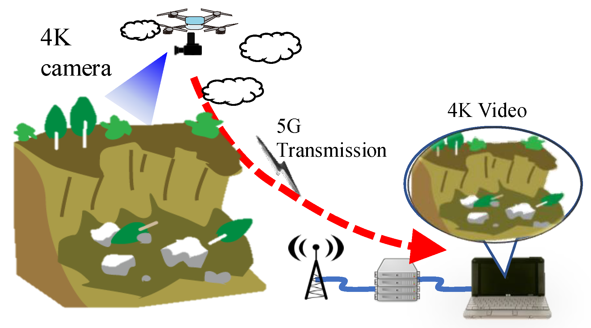
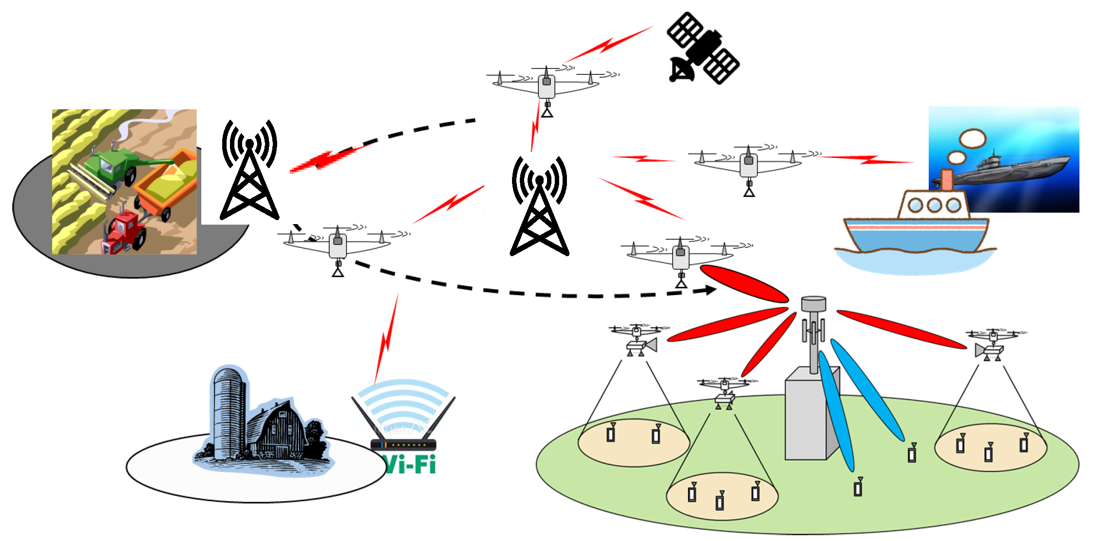
1. Introduction
- We propose a handover method based on signal-to-interference-plus-noise ratio (SINR) that includes multipath interference considering obstacles such as buildings in the environment where drones fly, instead of simple received power. Then, the effectiveness of the method was confirmed.
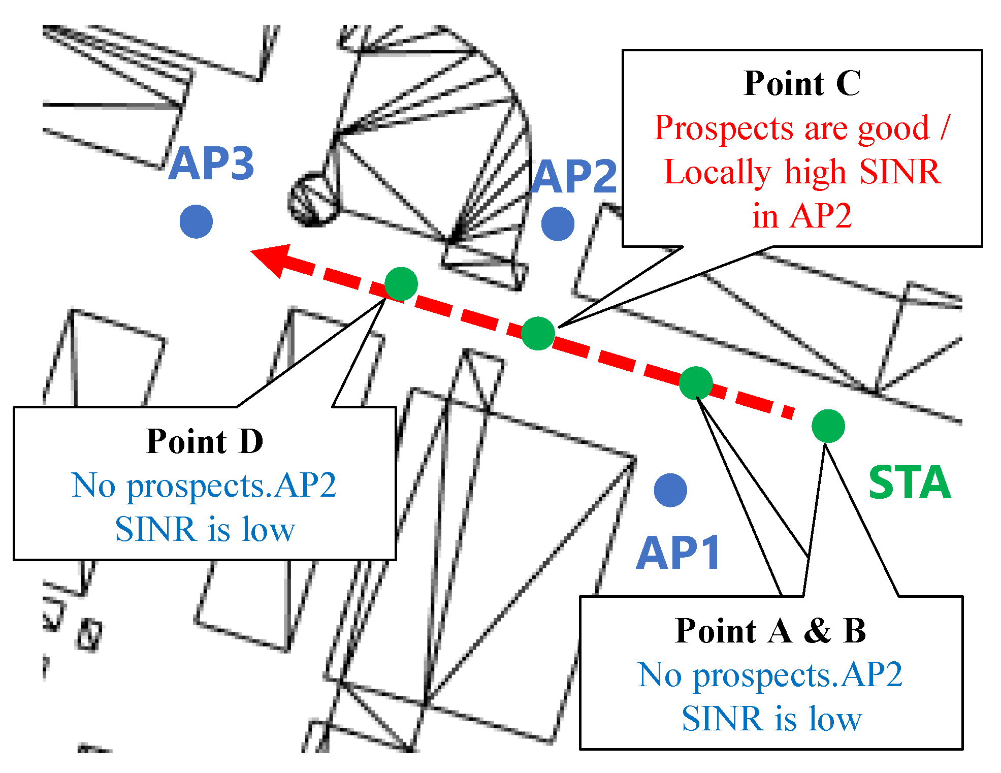
- We proposed a method to solve the problem of locally high SINR during the period when drones are flying and the communication speed is reduced due to frequent handovers, confirmed the effectiveness of the method, and determined the optimal flight speed.
- Because drone communications are subject to significant changes in reflection and diffraction from buildings and other objects depending on flight speed, the new cross-layer simulator was developed to determine throughput characteristics above the IP layer, including multipath interference due to propagation characteristics and signal processing performance, enabling evaluation in a three-dimensional virtual space close to the actual environment.
2. Related Work
2.1. Introduction of Relay Technology by Drone
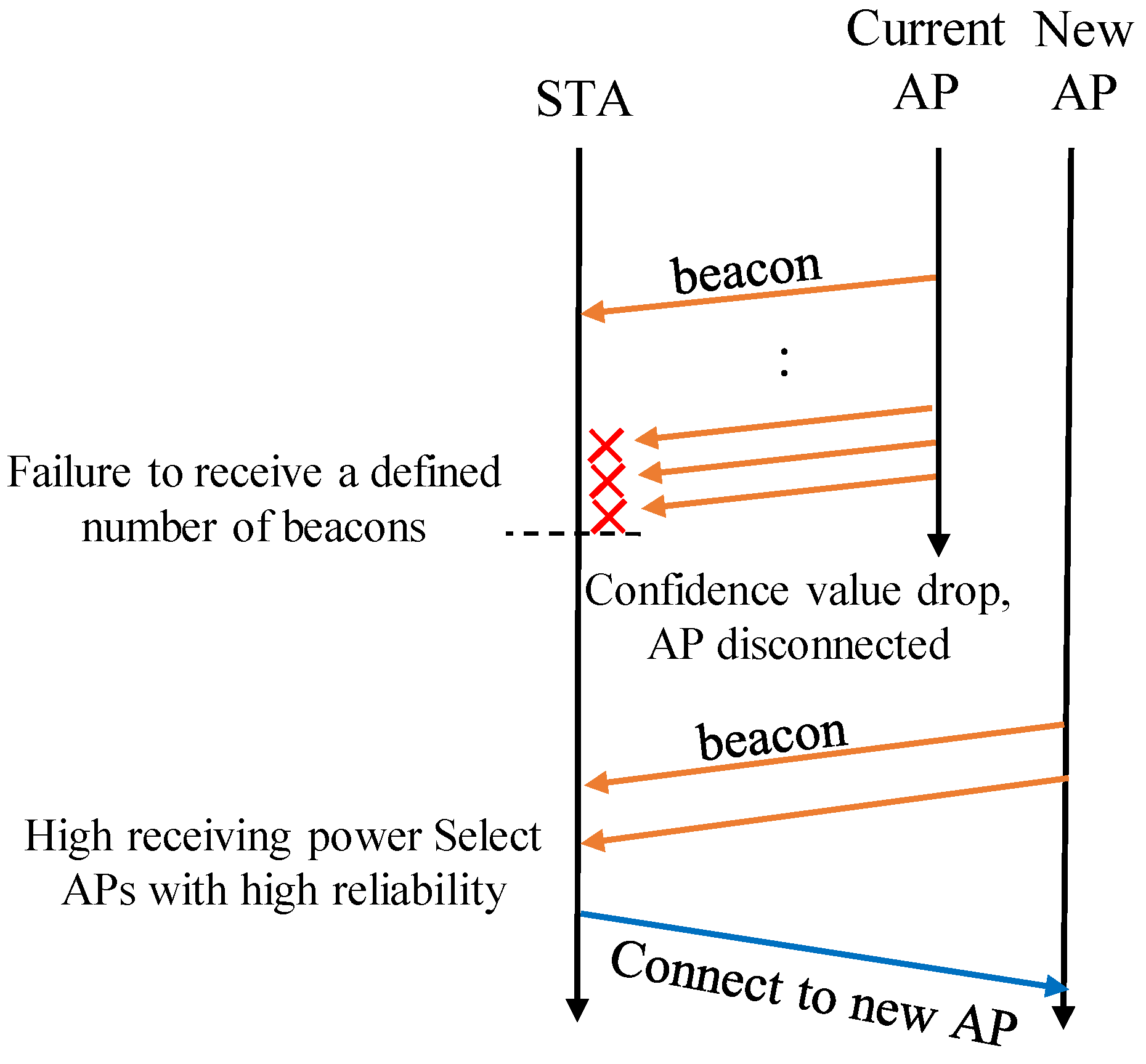
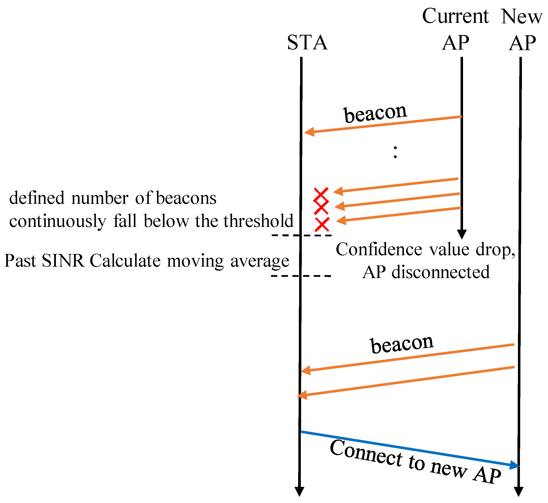
2.2. Conventional Methods and Issues
3. How to Evaluate Flying Drones
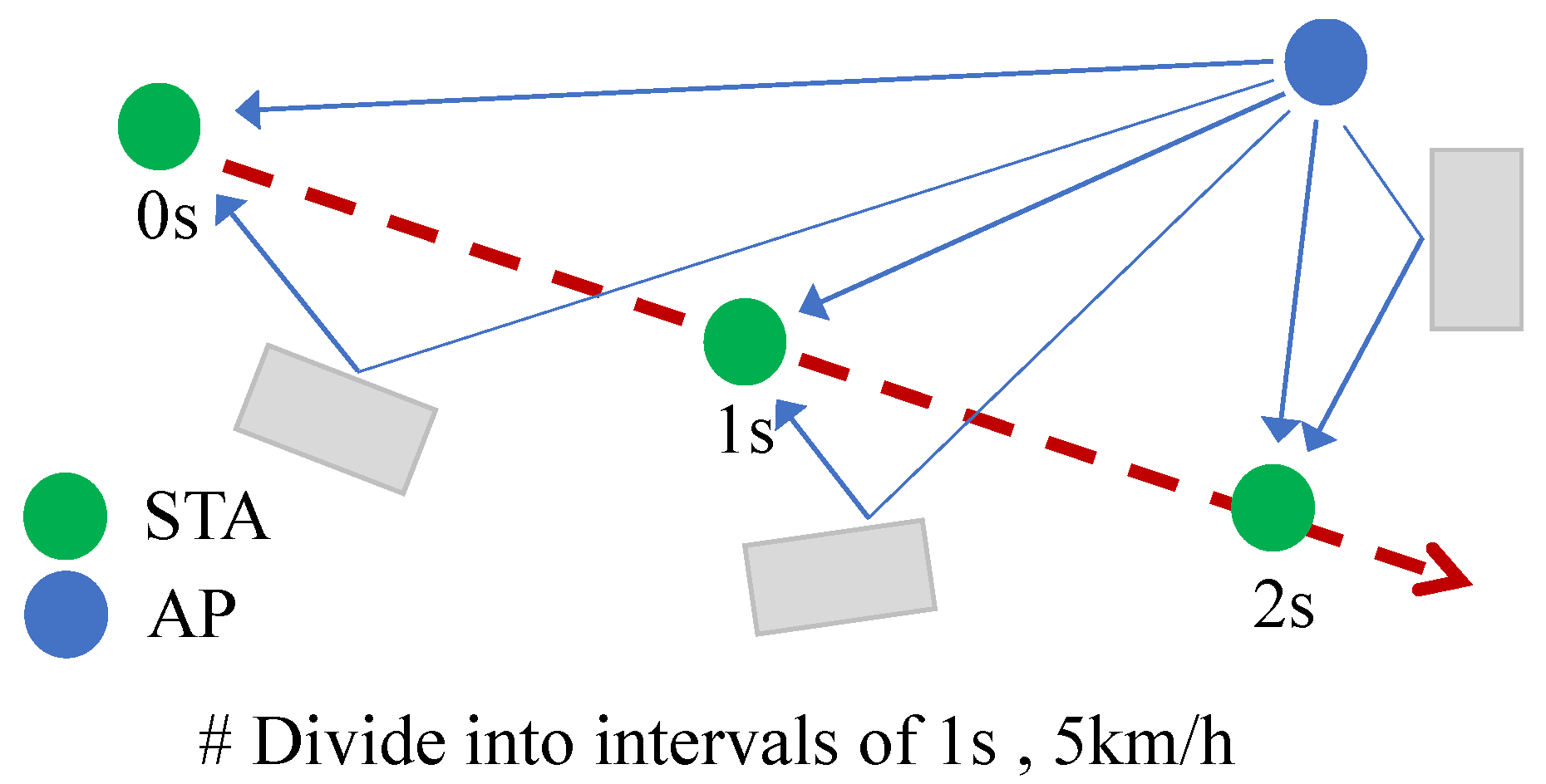
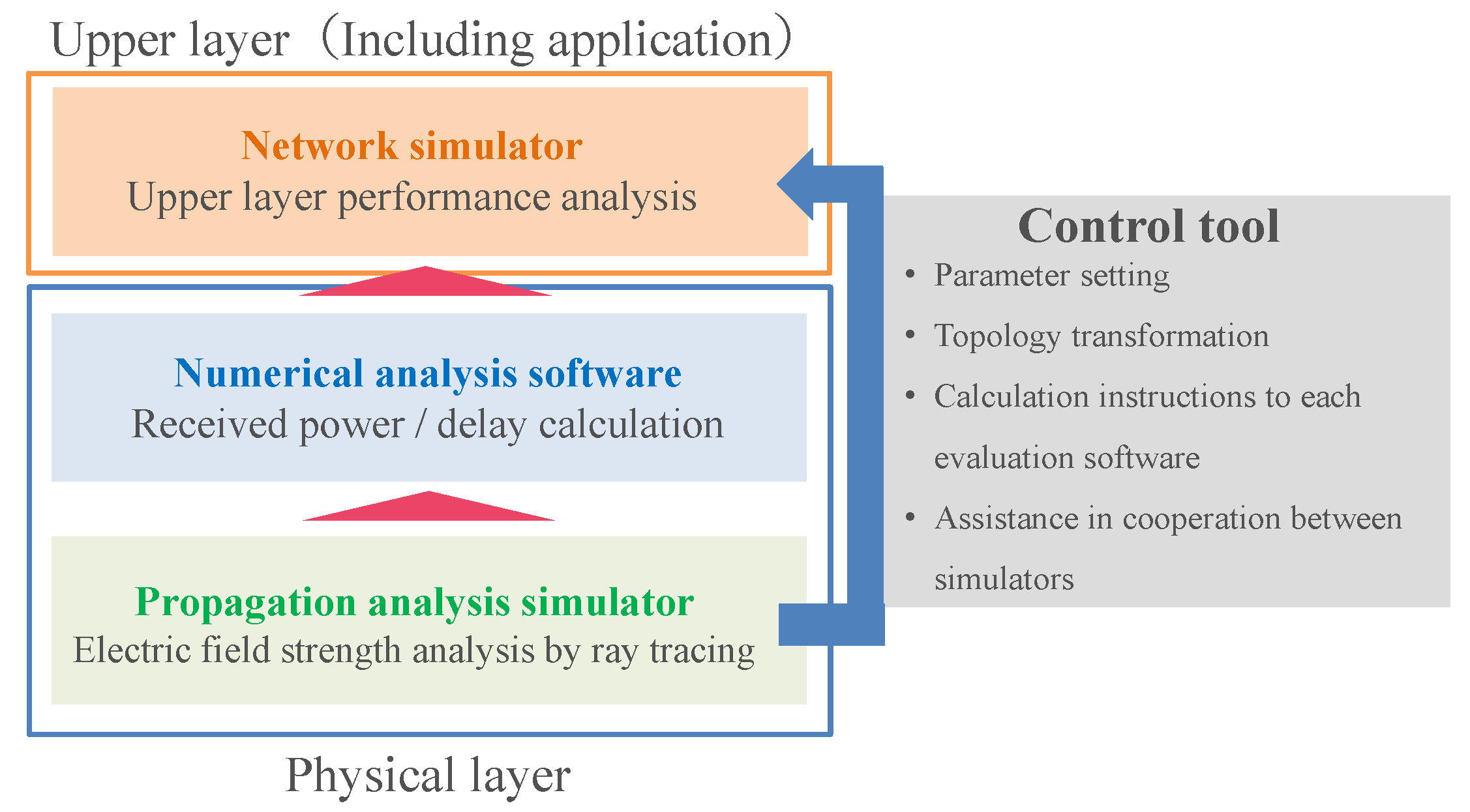
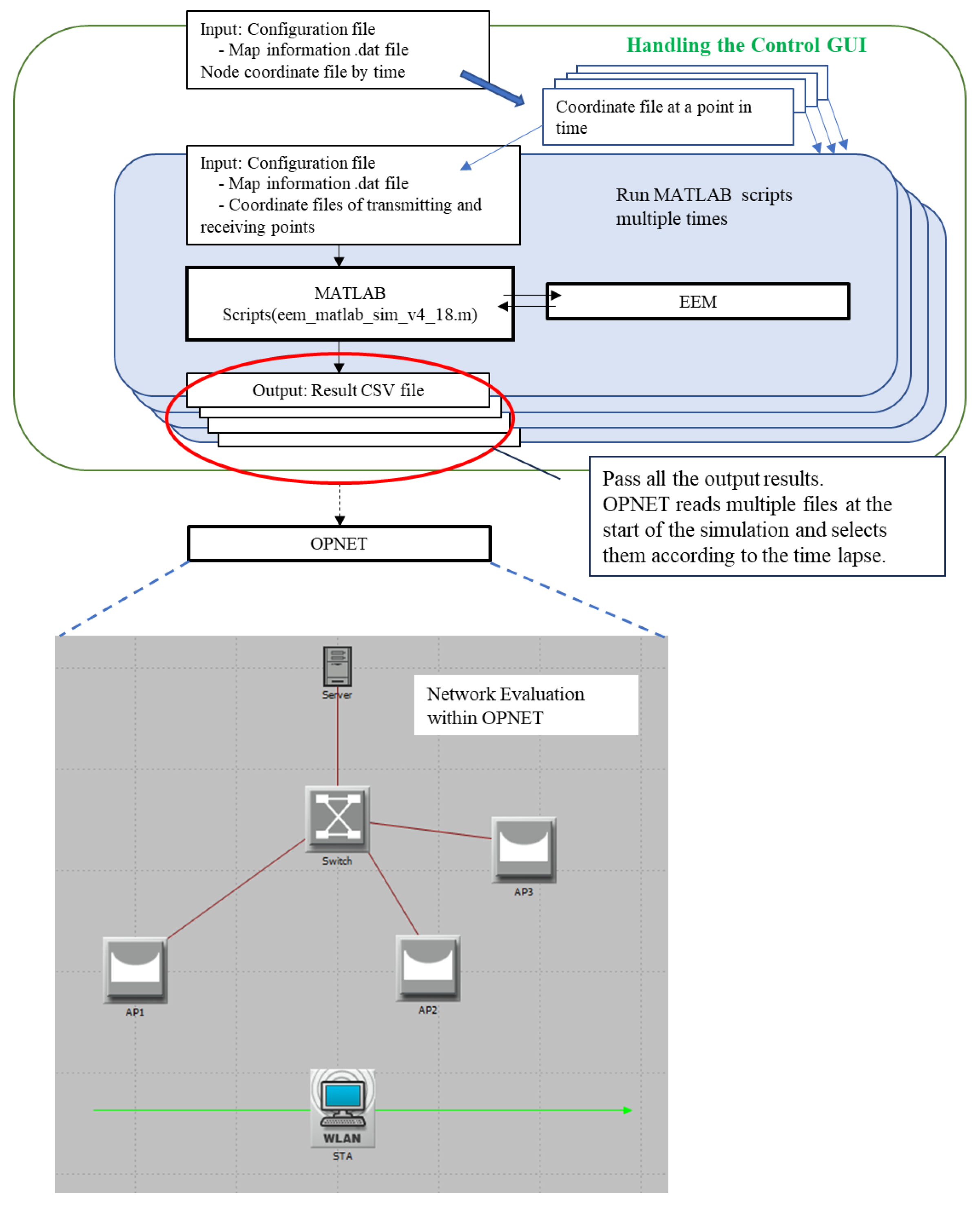
3.1. Overview of 3D Cross Layer Simulator
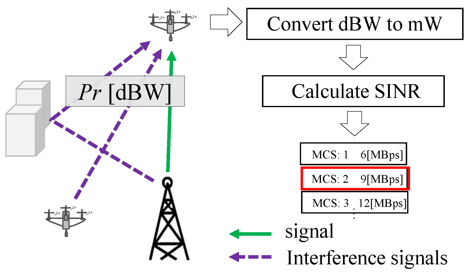
3.2. Power Calculation Method in 3D Cross Layer Simulator
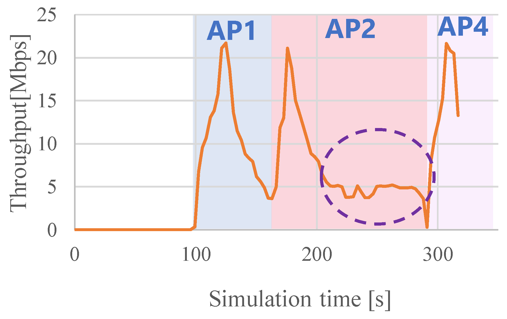
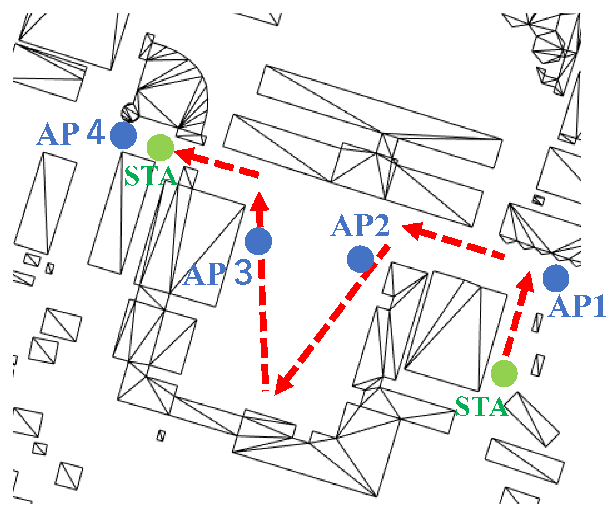
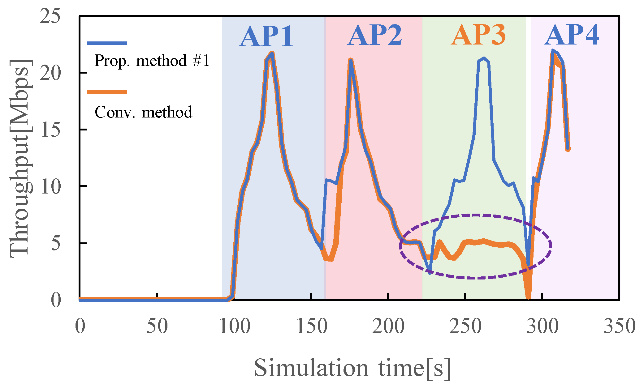
3.3. Evaluation Results of Conventional Methods
4. Proposal Method According to the Issue
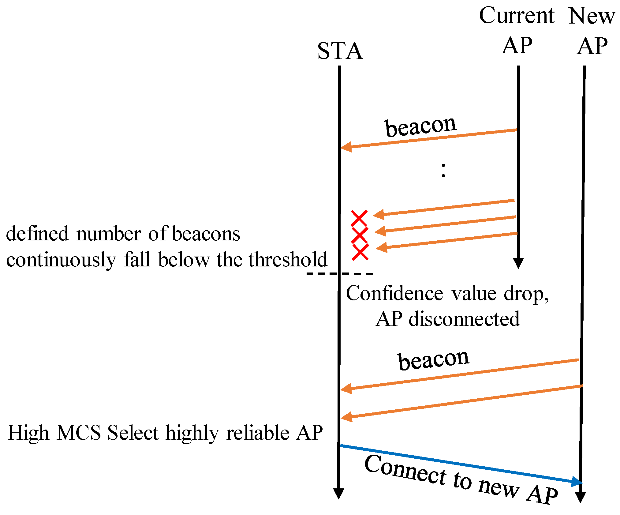
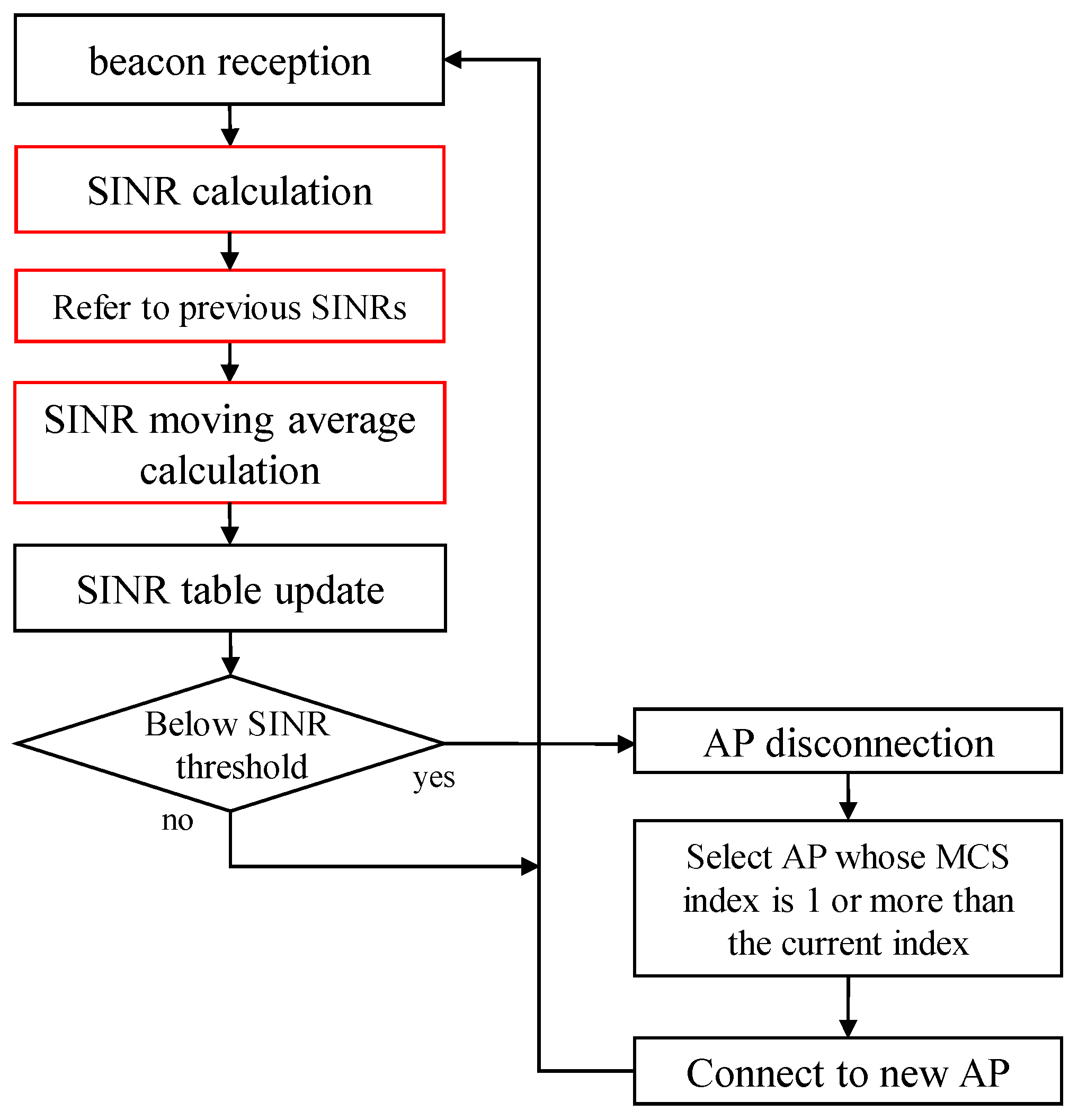
- Proposed method #1: In the conventional method, a handover to a better-conditioned base station cannot be performed unless a beacon failure occurs. In proposed method #1, the handover decision is based on a threshold instead of beacon reception. The proposed method solves this problem by actively performing handovers from an AP with a low transmission rate to another AP with good conditions.
- Proposed method #2: Since proposed method #1 performs handover aggressively, if a connection is attempted with a base station whose reception power is momentarily high due to the influence of buildings, etc., the reception power drops immediately and handover is performed again immediately, which increases the number of handover attempts. To solve this problem, the number of handover attempts can be reduced by eliminating base stations with instantaneously high received power from handover candidates by acquiring a moving average with reference to the past received power.
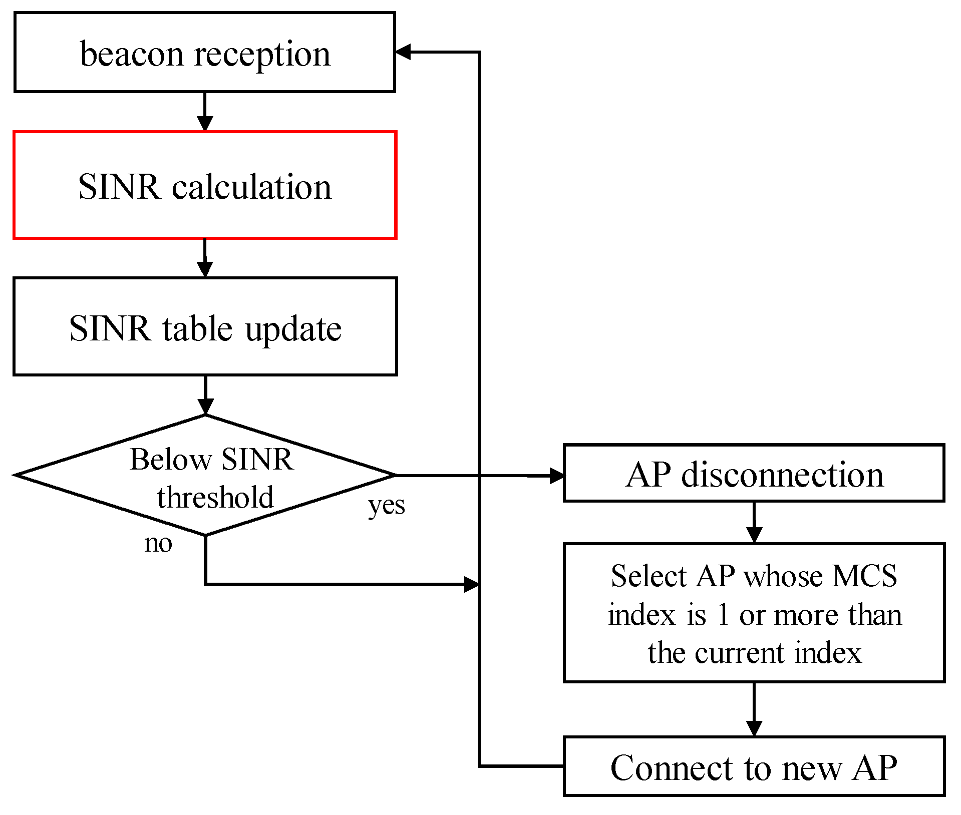
4.1. Overview of Proposed Method #1
- if (MCS index ≥ 1, AP exists)
- Handover to the AP with the best SINR among the applicable APs.
- else if (MCS index ≥ 1, AP does not exist)
- Handover to the AP with the best SINR among the APs with the same MCS index as the current one.
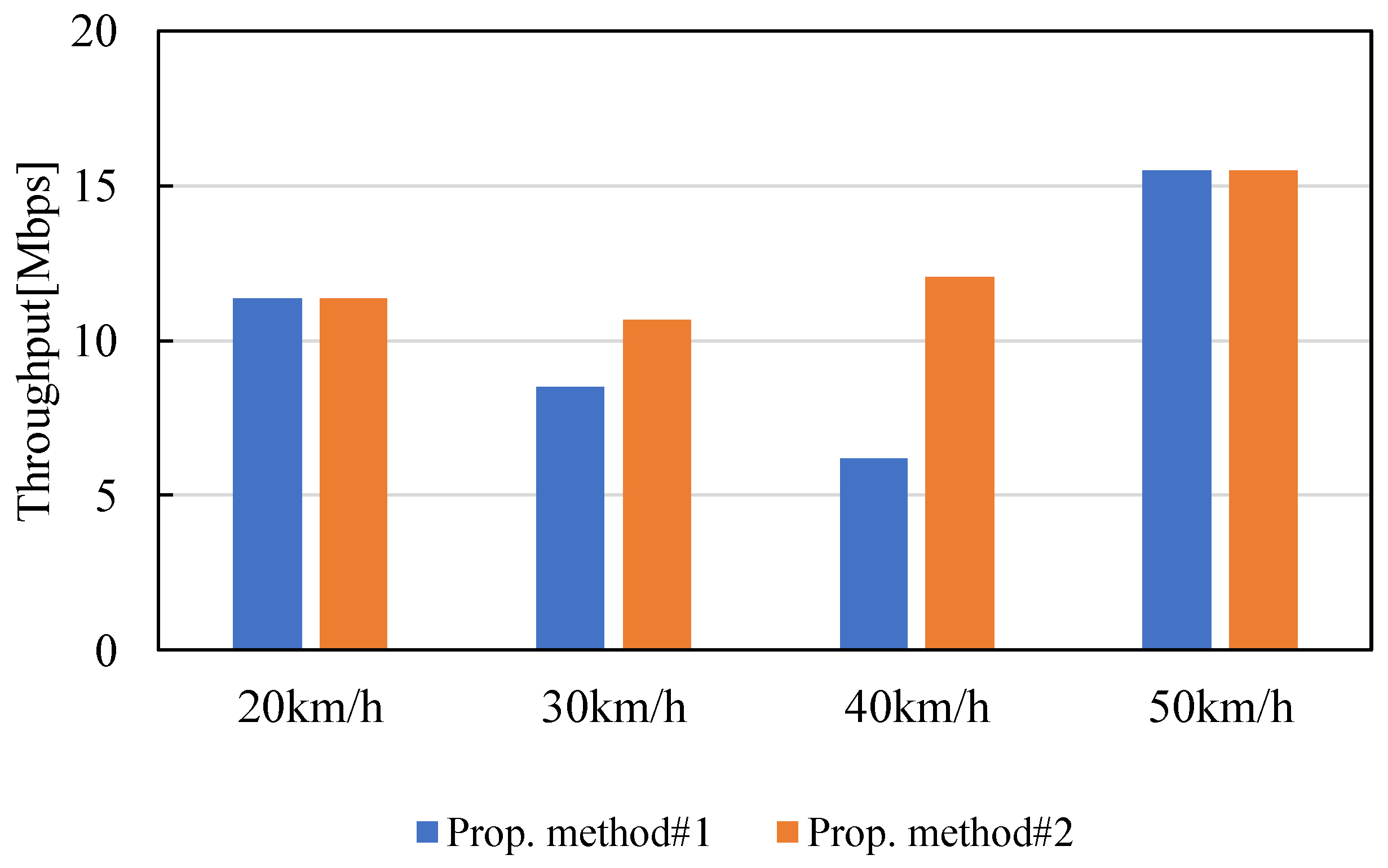
4.2. Evaluation Method and Results of Proposed Method #1
4.3. Overview of Proposed Method #2
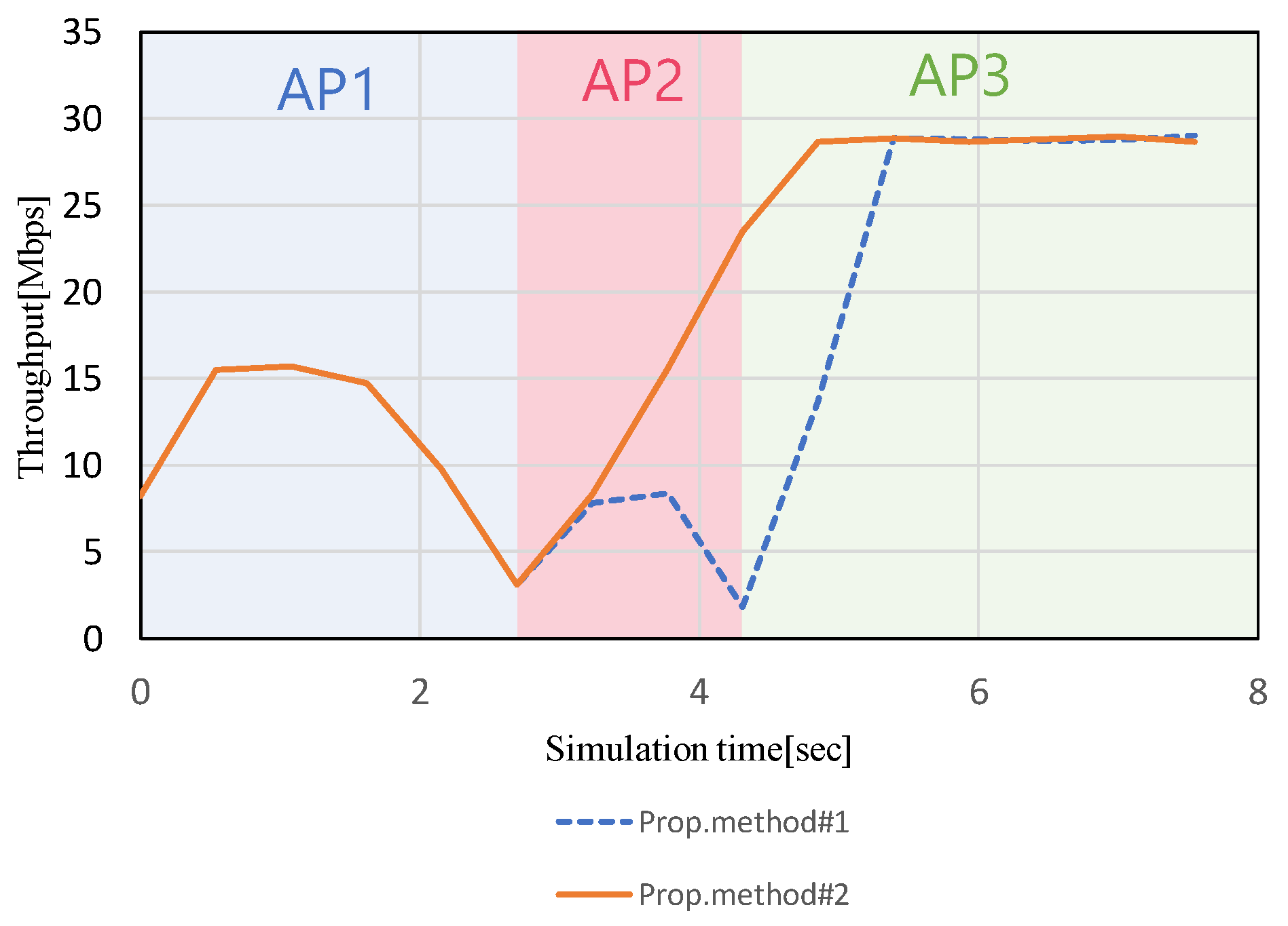
4.4. Evaluation Method and Results of Proposed Method #2
5. Conclusions
Author Contributions
Funding
Data Availability Statement
Conflicts of Interest
References
- 3rd Generation Partnership Project. TS 23.501: Technical Specification Group Services and System Aspects; System Architecture for the 5G System; Stage 2 (Release 16). 3GPP. July 2020. Available online: https://portal.3gpp.org/desktopmodules/Specifications/SpecificationDetails.aspx?specificationId=3493 (accessed on 8 December 2023).
- Qi, W.; Wang, H.; Xia, X.; Mei, C.; Liu, Y.; Xing, Y. Research on Novel Type of Non Terrestrial Network Architecture for 6G. In Proceedings of the 2023 International Wireless Communications and Mobile Computing (IWCMC), Marrakesh, Morocco, 19–23 June 2023; pp. 1281–1285. [Google Scholar] [CrossRef]
- Kafle, V.P.; Sekiguchi, M.; Asaeda, H.; Harai, H. Integrated Network Control Architecture for Terrestrial and Non-Terrestrial Network Convergence in Beyond 5G Systems. In Proceedings of the 2022 ITU Kaleidoscope-Extended Reality—How to Boost Quality of Experience and Interoperability, Accra, Ghana, 7–9 December 2022; pp. 1–9. [Google Scholar] [CrossRef]
- Yue, Y.; Tang, X.; Yang, W.; Zhang, X.; Zhang, Z.; Gao, C.; Xu, L. Delay-aware and Resource-efficient VNF placement in 6G Non-Terrestrial Networks. In Proceedings of the 2023 IEEE Wireless Communications and Networking Conference (WCNC), Glasgow, UK, 26–29 March 2023; pp. 1–6. [Google Scholar] [CrossRef]
- Sattarzadeh, A.; Liu, Y.; Mohamed, A.; Song, R.; Xiao, P.; Song, Z.; Zhang, H.; Tafazolli, R.; Niu, C. Satellite-Based Non-Terrestrial Networks in 5G: Insights and Challenges. IEEE Access 2022, 10, 11274–11283. [Google Scholar] [CrossRef]
- Majamaa, M.; Martikainen, H.; Sormunen, L.; Puttonen, J. Adaptive Multi-Connectivity Activation for Throughput Enhancement in 5G and Beyond Non-Terrestrial Networks. In Proceedings of the 2022 International Conference on Software, Telecommunications and Computer Networks (SoftCOM), Split, Croatia, 22–24 September 2022; pp. 1–5. [Google Scholar] [CrossRef]
- Evans, B. 6G Satellite Communications. In Proceedings of the 2022 27th Asia Pacific Conference on Communications (APCC), Jeju Island, Republic of Korea, 19–21 October 2022; pp. 175–177. [Google Scholar] [CrossRef]
- Kawanishi, T. Seamless Networks for beyond 5G. IEEE Future Netw. Tech Focus 2019, 3. [Google Scholar]
- Cassiau, N.; Kim, I.; Strinati, E.C.; Noh, G.; Pietrabissa, A.; Arnal, F.; Casati, G.; Choi, T.; Choi, Y.J.; Chung, H.; et al. 5G-ALLSTAR: Beyond 5G Satellite-Terrestrial Multi-Connectivity. In Proceedings of the 2022 Joint European Conference on Networks and Communications & 6G Summit (EuCNC/6G Summit), Grenoble, France, 7–10 June 2022; pp. 148–153. [Google Scholar] [CrossRef]
- Shayea, I.; Ergen, M.; Azmi, M.H.; Çolak, S.A.; Nordin, R.; Daradkeh, Y.I. Key Challenges, Drivers and Solutions for Mobility Management in 5G Networks: A Survey. IEEE Access 2020, 8, 172534–172552. [Google Scholar] [CrossRef]
- Lei, L.; Yuan, Y.; Vu, T.X.; Chatzinotas, S.; Minardi, M.; Montoya, J.F.M. Dynamic-Adaptive AI Solutions for Network Slicing Management in Satellite-Integrated B5G Systems. IEEE Netw. 2021, 35, 91–97. [Google Scholar] [CrossRef]
- Ozger, M.; Godor, I.; Nordlow, A.; Heyn, T.; Pandi, S.; Peterson, I.; Viseras, A.; Holis, J.; Raffelsberger, C.; Kercek, A.; et al. 6G for Connected Sky: A Vision for Integrating Terrestrial and Non-Terrestrial Networks. In Proceedings of the 2023 Joint European Conference on Networks and Communications & 6G Summit (EuCNC/6G Summit), Gothenburg, Sweden, 6–9 June 2023; pp. 711–716. [Google Scholar] [CrossRef]
- Available online: https://www.soumu.go.jp/johotsusintokei/whitepaper/ja/r05/html/nd242330.html (accessed on 8 December 2023).
- Li, S.; Chen, Q.; Meng, W.; Li, C. Civil Aircraft Assisted Space-Air-Ground Integrated Networks: An Innovative NTN of 5G and Beyond. IEEE Wirel. Commun. 2022, 29, 64–71. [Google Scholar] [CrossRef]
- Harounabadi, M.; Heyn, T. Toward Integration of 6G-NTN to Terrestrial Mobile Networks: Research and Standardization Aspects. IEEE Wirel. Commun. 2023, 30, 20–26. [Google Scholar] [CrossRef]
- Cui, H.; Zhang, J.; Geng, Y.; Xiao, Z.; Sun, T.; Zhang, N.; Liu, J.; Wu, Q.; Cao, X. Space-air-ground integrated network (SAGIN) for 6G: Requirements, architecture and challenges. China Commun. 2022, 19, 90–108. [Google Scholar] [CrossRef]
- Dureppagari, H.K.; Saha, C.; Dhillon, H.S.; Buehrer, R.M. NTN-Based 6G Localization: Vision, Role of LEOs, and Open Problems. IEEE Wirel. Commun. 2023, 30, 44–51. [Google Scholar] [CrossRef]
- Azari, M.M.; Solanki, S.; Chatzinotas, S.; Kodheli, O.; Sallouha, H.; Colpaert, A.; Montoya, J.F.M.; Pollin, S.; Haqiqatnejad, A.; Mostaani, A.; et al. Evolution of Non-Terrestrial Networks From 5G to 6G: A Survey. IEEE Commun. Surv. Tutorials 2022, 24, 2633–2672. [Google Scholar] [CrossRef]
- Gu, X.; Zhang, G. A survey on UAV-assisted wireless communications: Recent advances and future trends. Comput. Commun. 2023, 208, 44–78. [Google Scholar] [CrossRef]
- Li, B.; Zhao, S.; Miao, R.; Zhang, R. A survey on unmanned aerial vehicle relaying networks. IET Commun. 2021, 15, 1262–1272. [Google Scholar] [CrossRef]
- Available online: https://www.docomo.ne.jp/info/news_release/2022/02/09_00.html (accessed on 8 December 2023).
- Open Systems Interconnection—Basic Reference Model; International Organization for Standardization ISO: Geneva, Switzerland, 1984.
- IEEE 802.11-1997; Information Technology—Telecommunications and Information Exchange between Systems—Local and Metropolitan Area Networks—Specific Requirements—Part 11: Wireless LAN Medium Access Control (MAC) and Physical Layer (PHY) Specifications. IEEE: Piscataway, NJ, USA, 1997.
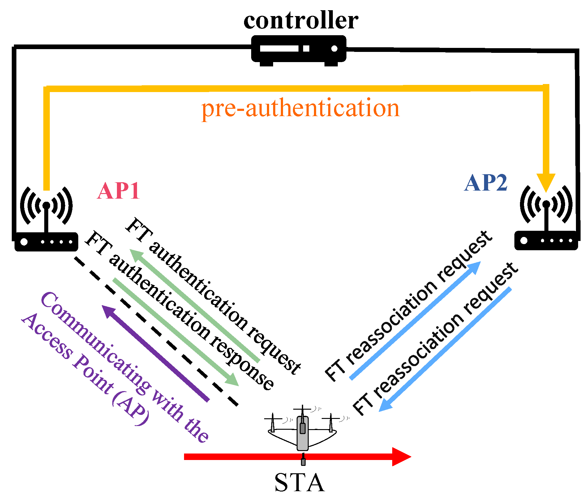
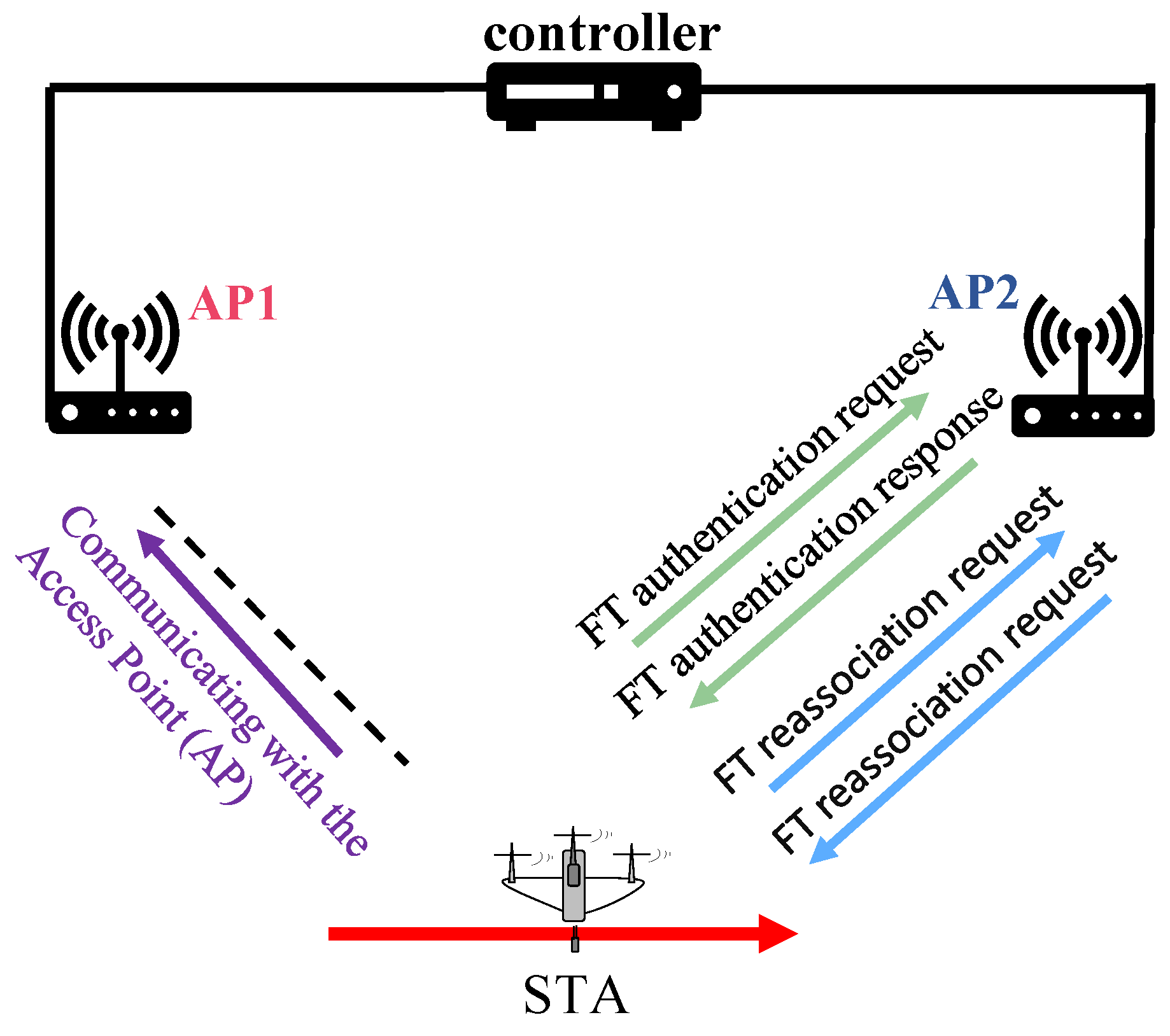
- IEEE Std 802.11r-2008; Amendment 2: Fast BSS Transition. IEEE: Piscataway, NJ, USA, 2008.
- Chou, F.-Y.; Liao, I.-J.; Li, Y.-C.; Wu, T.-Y.; Lee, W.-T. A Pre-registered Handoff Scheme in IEEE 802.11r Wireless Local Area Networks. In Proceedings of the 2010 International Conference on Communications and Mobile Computing, Shenzhen, China, 12–14 April 2010; pp. 466–470. [Google Scholar] [CrossRef]
- IEEE Std 802.11r-2008; IEEE Standard for Information Technology—Local and Metropolitan Area Networks—Specific Requirements—Part 11: Wireless LAN Medium Access Control (MAC) and Physical Layer (PHY) Specifications Amendment 2: Fast Basic Service Set (BSS) Transition. Amendment to IEEE Std 802.11-2007 as Amended by IEEE Std 802.11k-2008. IEEE: Piscataway, NJ, USA, 2008; pp. 1–126. [CrossRef]
- Clancy, T.C. Secure handover in enterprise WLANs: Capwap, hokey, and IEEE 802.11R. IEEE Wirel. Commun. 2008, 15, 80–85. [Google Scholar] [CrossRef]
- Hiraguri, T.; Nishimori, K.; Shitara, I.; Mitsui, T.; Shindo, T.; Kimura, T.; Matsuda, T.; Yoshino, H. A Cooperative Transmission Scheme in Drone-Based Networks. IEEE Trans. Veh. Technol. 2020, 69, 2905–2914. [Google Scholar] [CrossRef]
- Matsumura, N.; Nishimori, K.; Taniguchi, R.; Mitsui, T.; Hiraguri, T. Effect of Propagation Environment Control Method Using Drone MIMO Relay Station. In Proceedings of the 2018 International Symposium on Antennas and Propagation (ISAP), Busan, Republic of Korea, 23–26 October 2018; pp. 1–2. [Google Scholar]
- Wang, X.; Mi, Z.; Wang, H.; Zhao, N. Performance test and analysis of multi-hop network based on UAV Ad Hoc network experiment. In Proceedings of the 2017 9th International Conference on Wireless Communications and Signal Processing (WCSP), Nanjing, China, 11–13 October 2017; pp. 1–6. [Google Scholar] [CrossRef]
- Khuwaja, A.A.; Chen, Y.; Zhao, N.; Alouini, M.-S.; Dobbins, P. A Survey of Channel Modeling for UAV Communications. IEEE Commun. Surv. Tutorials 2018, 20, 2804–2821. [Google Scholar] [CrossRef]
- Khawaja, W.; Guvenc, I.; Matolak, D.W.; Fiebig, U.-C.; Schneckenburger, N. A Survey of Air-to-Ground Propagation Channel Modeling for Unmanned Aerial Vehicles. IEEE Commun. Surv. Tutorials 2019, 21, 2361–2391. [Google Scholar] [CrossRef]
- Jiang, H.; Zhang, Z.; Wu, L.; Dang, J. Three-Dimensional Geometry-Based UAV-MIMO Channel Modeling for A2G Communication Environments. IEEE Commun. Lett. 2018, 22, 1438–1441. [Google Scholar] [CrossRef]
- Bian, J.; Wang, C.-X.; Liu, Y.; Tian, J.; Qiao, J.; Zheng, X. 3D Non-Stationary Wideband UAV-to-Ground MIMO Channel Models Based on Aeronautic Random Mobility Model. IEEE Trans. Veh. Technol. 2021, 70, 11154–11168. [Google Scholar] [CrossRef]
- Chang, H.; Wang, C.X.; Liu, Y.; Huang, J.; Sun, J.; Zhang, W.; Gao, X. A Novel Nonstationary 6G UAV-to-Ground Wireless Channel Model With 3-D Arbitrary Trajectory Changes. IEEE Internet Things J. 2021, 8, 9865–9877. [Google Scholar] [CrossRef]
- Fu, B.; Xiao, Y.; Deng, H.; Zeng, H. A Survey of Cross-Layer Designs in Wireless Networks. IEEE Commun. Surv. Tutorials 2014, 16, 110–126. [Google Scholar] [CrossRef]
- Available online: https://www.mathworks.com/?sïij¿tid=gnïij¿logo (accessed on 8 December 2023).
- Available online: https://support.riverbed.com/content/support.html (accessed on 8 December 2023).
- IEEE Std 802.11ax-2021; IEEE Standard for Information Technology–Telecommunications and Information Exchange between Systems Local and Metropolitan Area Networks–Specific Requirements Part 11: Wireless LAN Medium Access Control (MAC) and Physical Layer (PHY) Specifications Amendment 1: Enhancements for High-Efficiency WLAN. Amendment to IEEE Std 802.11-2020. IEEE: Piscataway, NJ, USA, 2021; pp. 1–767. [CrossRef]
- He, Y.; Wang, D.; Huang, F.; Zhang, R.; Gu, X.; Pan, J. A V2I and V2V Collaboration Framework to Support Emergency Communications in ABS-Aided Internet of Vehicles. IEEE Trans. Green Commun. Netw. 2023, 7, 2038–2051. [Google Scholar] [CrossRef]
- Available online: https://fgd.gsi.go.jp/download/menu.php (accessed on 8 December 2023).
- IEEE 802.11g-2003; Information Technology—Telecommunications and Information Exchange between Systems—Local and Metropolitan Area Networks—Specific Requirements—Part 11: Wireless LAN Medium Access Control (MAC) and Physical Layer (PHY) Specifications—Amendment 4: Further Higher Data Rate Extension in the 2.4 GHz Band. IEEE: Piscataway, NJ, USA, 2003.


| Conv. Method | |
|---|---|
| Comn. method | IEEE802.11g standard |
| Frequency band | 2.4 GHz |
| Transmission power | 0.2 mW |
| Flight speed | 5 km/h |
| STA and AP height | 5 m above ground |
| Hand over method | Beacon reception failure counts |
| Conv. Method | Prop. #1 | Prop. #2 | |
|---|---|---|---|
| Communication method | IEEE802.11g standard | ||
| Frequency band | 2.4 GHz | ||
| Transmission power | 0.2 mW | ||
| Flight speed | 5 km/h | ||
| Hand over method | Beacon counts | SINR threshold | SINR moving average |
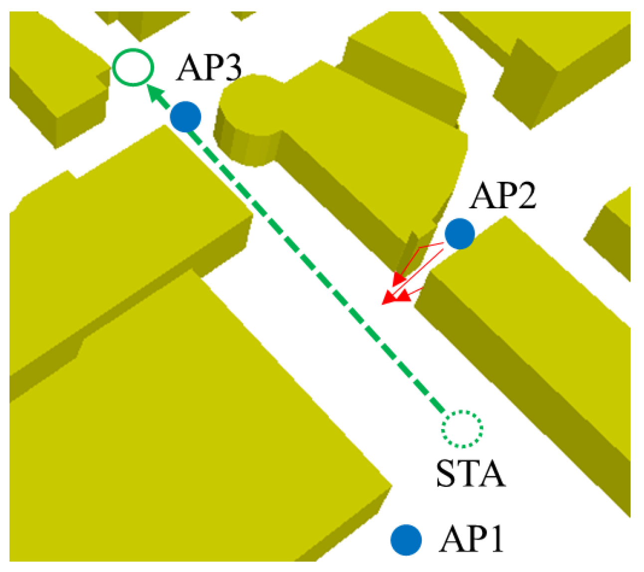
| Point | AP1 | AP2 | AP3 |
|---|---|---|---|
| A | 28 | 0 | 0 |
| B | 15 | 3 | 14 |
| C | 3 | 30 | 28 |
| C (Ave.) | 9 | 16.5 | 21 |
| D | 0 | 3 | 30 |
Disclaimer/Publisher’s Note: The statements, opinions and data contained in all publications are solely those of the individual author(s) and contributor(s) and not of MDPI and/or the editor(s). MDPI and/or the editor(s) disclaim responsibility for any injury to people or property resulting from any ideas, methods, instructions or products referred to in the content. |
© 2024 by the authors. Licensee MDPI, Basel, Switzerland. This article is an open access article distributed under the terms and conditions of the Creative Commons Attribution (CC BY) license (https://creativecommons.org/licenses/by/4.0/).
Share and Cite
Hirata, K.; Hiraguri, T.; Kimura, T.; Matsuda, T.; Imai, T.; Hirokawa, J.; Maruta, K.; Ujigawa, S. Study on Drone Handover Methods Suitable for Multipath Interference Due to Obstacles. Drones 2024, 8, 32. https://doi.org/10.3390/drones8020032
Hirata K, Hiraguri T, Kimura T, Matsuda T, Imai T, Hirokawa J, Maruta K, Ujigawa S. Study on Drone Handover Methods Suitable for Multipath Interference Due to Obstacles. Drones. 2024; 8(2):32. https://doi.org/10.3390/drones8020032
Chicago/Turabian StyleHirata, Kakeru, Takefumi Hiraguri, Tomotaka Kimura, Takahiro Matsuda, Tetsuro Imai, Jiro Hirokawa, Kazuki Maruta, and Satoshi Ujigawa. 2024. "Study on Drone Handover Methods Suitable for Multipath Interference Due to Obstacles" Drones 8, no. 2: 32. https://doi.org/10.3390/drones8020032
APA StyleHirata, K., Hiraguri, T., Kimura, T., Matsuda, T., Imai, T., Hirokawa, J., Maruta, K., & Ujigawa, S. (2024). Study on Drone Handover Methods Suitable for Multipath Interference Due to Obstacles. Drones, 8(2), 32. https://doi.org/10.3390/drones8020032