Article

In Situ VTOL Drone-Borne Observations of Temperature and Relative Humidity over Dome C, Antarctica

1
Centre National de Recherches Météorologiques (CNRM), Université de Toulouse, Météo-France, Centre National de le Recherche Scientifique (CNRS), 31057 Toulouse, France
2
Laboratoire d’Aérologie, Université de Toulouse, Centre National de la Recherche Scientifique (CNRS), Université Paul Sabatier, 31400 Toulouse, France
3
Agenzia Nazionale per le Nuove Tecnologie, l’energia e lo Sviluppo Economico Sostenibile (ENEA), 00196 Roma, Italy
4
Istituto Nazionale di Ottica-Consiglio Nazionale delle Ricerche (INO-CNR), 50019 Sesto Fiorentino, Italy
5
DeltaQuad, 1115 AD Duivendrecht, The Netherlands
*
Author to whom correspondence should be addressed.
Drones 2023, 7(8), 532; https://doi.org/10.3390/drones7080532
Submission received: 8 June 2023 / Revised: 26 July 2023 / Accepted: 26 July 2023 / Published: 15 August 2023
(This article belongs to the Special Issue Unmanned Aerial Vehicles in Atmospheric Research)

Abstract

:
The Antarctic atmosphere is rapidly changing, but there are few observations available in the interior of the continent to quantify this change due to few ground stations and satellite measurements. The Concordia station is located on the East Antarctic Plateau (75° S, 123° E, 3233 m above mean sea level), one of the driest and coldest places on Earth. Several remote sensing instruments are available at the station to probe the atmosphere, together with operational meteorological sensors. In order to observe in situ clouds, temperature, relative humidity and supercooled liquid water (SLW) at a high vertical resolution, a new project based on the use of an unmanned aerial vehicle (drone) vertical take-off and landing from the DeltaQuad Company has been set up at Concordia. A standard Vaisala pressure, temperature and relative humidity sensor was installed aboard the drone coupled to an Anasphere SLW sensor. A total of thirteen flights were conducted from 24 December 2022 to 17 January 2023: nine technology flights and four science flights (on 2, 10, 11 and 13 January 2023). Drone-based temperature and relative humidity profiles were compared to (1) the balloon-borne meteorological observations at 12:00 UTC, (2) the ground-based microwave radiometer HAMSTRAD and (3) the outputs from the numerical weather prediction models ARPEGE and AROME. No SLW clouds were present during the period of observations. Despite technical issues with drone operation due to the harsh environments encountered (altitude, temperature and geomagnetic field), the drone-based observations were consistent with the balloon-borne observations of temperature and relative humidity. The radiometer showed a systematic negative bias in temperature of 2 °C, and the two models were, in the lowermost troposphere, systematically warmer (by 2–4 °C) and moister (by 10–30%) than the drone-based observations. Our study shows the great potential of a drone to probe the Antarctic atmosphere in situ at very high vertical resolution (a few meters).

1. Introduction

Clouds in Antarctica affect the Earth’s radiation balance, both directly at high southern latitudes and indirectly, at the global level through complex teleconnections [1]. Depending on the nature of the clouds (liquid/solid), their vertical/horizontal distributions (low/high altitude, coastal/deep interior) and the season, the fractional cloud cover strongly evolves [2] from about 50 to 60% around the South Pole to 80–90% near the coast. Clouds are mainly composed of ice above the continent, whereas the abundance of supercooled liquid water (SLW, water that remains in liquid phase below 0 °C) clouds depends on temperature and liquid/ice fraction decreases sharply poleward [3,4,5,6,7], and is two to three times lower over the Eastern Antarctic Plateau than over the Western Antarctic [8]. SLW clouds (SLWCs) are observed to occur more frequently than in weather model simulations, leading to biases in surface radiation budget estimates [9,10,11].
The Dome C (Concordia) station, jointly operated by French and Italian institutions in the Eastern Antarctic Plateau (75°06′ S, 123°21′ E, 3233 m above mean sea level, amsl), is one of the driest and coldest places on Earth, with surface temperatures ranging from about −20 °C in summer to −70 °C in winter. For a decade, SLWCs have been observed remotely and analysed by combining observations with models [12]. During the Year Of Polar Prediction (YOPP) international campaign, SLWCs were detected in December 2018, with temperatures between −20 °C and −30 °C and liquid water path (LWP, the liquid water concentration integrated along the vertical dimension) between 2 and 20 g m−2, considerably impacting net surface radiation, which exceeded simulated values by 20–50 W m−2. During the summer campaign in 2021–2022, in situ SLW sondes were attached to meteorological balloons to observe the vertical distribution of SLWCs. The impact of the SLWCs on the surface radiation has also been statistically analysed, showing that temperature logarithmically increases from −36.0 °C to −16.0 °C when LWP increases from 1.0 to 14.0 g m−2, and SLWCs positively impact net surface radiation, which increases logarithmically by 0.0 to 50.0 W m−2 when LWP increases from 1.7 to 3.0 g m−2 (see [13] and references therein).
Unmanned aerial vehicles (UAVs, or drones) have become one of the most efficient tools to probe the planetary boundary layer (PBL). Ref. [14] underlined the potential of such observations to improve analyses and forecasts, especially for highly varying parameters like humidity. In recent decades, a large number of research groups worldwide have developed fixed-wing or multi-rotor-type instrumented platforms to explore the PBL. The quality of the observed and computed signals (such as wind, temperature, moisture, etc.) is variable from one platform to another. Ref. [15] compared the observations of 38 UAVs (both fixed-wing and multi-rotor type) and reported a spread in observations that was related to the sensors and/or the type of platform on which they were installed. UAVs, therefore, have become one of the most efficient tools for tackling different aspects of scientific data collection in Antarctica [16,17]. Drones can be used in mapping studies of ice and snow (topography, ice sheets, glaciers and sea ice), to determine the distribution and abundance of fauna (seals, birds, etc.) and to focus on atmospheric studies (air quality, aerosols, temperature, etc.). The use of drones was developed in our group a decade ago to study the development of the PBL in France [18]. As a consequence, we wanted to use this kind of vector again to observe the presence of SLWCs in situ in harsh environments such as the ones encountered in the Antarctic Eastern Plateau and couple these unique observations with in situ balloon-borne and ground-based measurements (microwave radiometer) together with the outputs from two numerical weather prediction (NWP) models. The concept was based on the same methodology as in previous studies on SLWCs with SLW sondes [19] attached to meteorological balloons. In the case of the drone, the SLW sonde is inserted into the onboard payload together with the meteorological sonde. The two sets of observations are transmitted in real time to the ground station. Observations have been made at Dome C, Antarctica, from December 2022 to January 2023 during the summer season when the presence of SLWCs is statistically at the highest point over the entire year, with a daily occurrence of the SLWCs (for a period greater than 2 h) as high as 50% [12].
The article is structured as follows. Section 2 deals with the instruments and models used in our analysis. Section 3 presents the methodology deployed to achieve our goals. The results are shown in Section 4 and discussed in Section 5 before conclusions are drawn in Section 6.

2. Instruments and Models

2.1. Drone

The drone used at Concordia has been developed by the DeltaQuad Company (https://www.deltaquad.com (accessed on 9 August 2023)). It is the DeltaQuad Pro Vertical Take-Off and Landing (VTOL) Unmanned Aerial Vehicle (UAV, hereafter referred to as drone). The drone has not been modified to meet the harsh of Concordia (Figure 1). The technical characteristics of the drone are synthetized in Table 1.
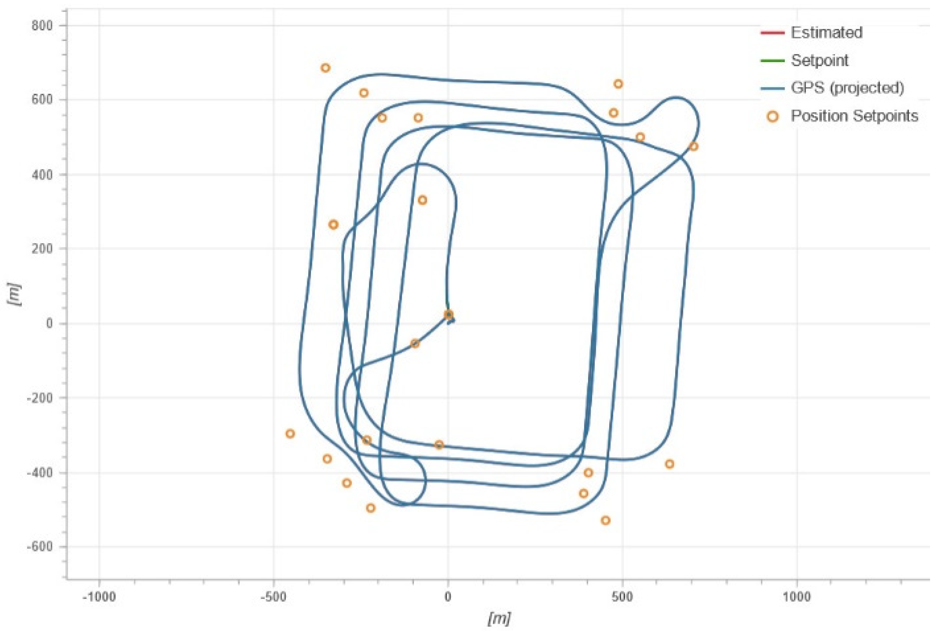
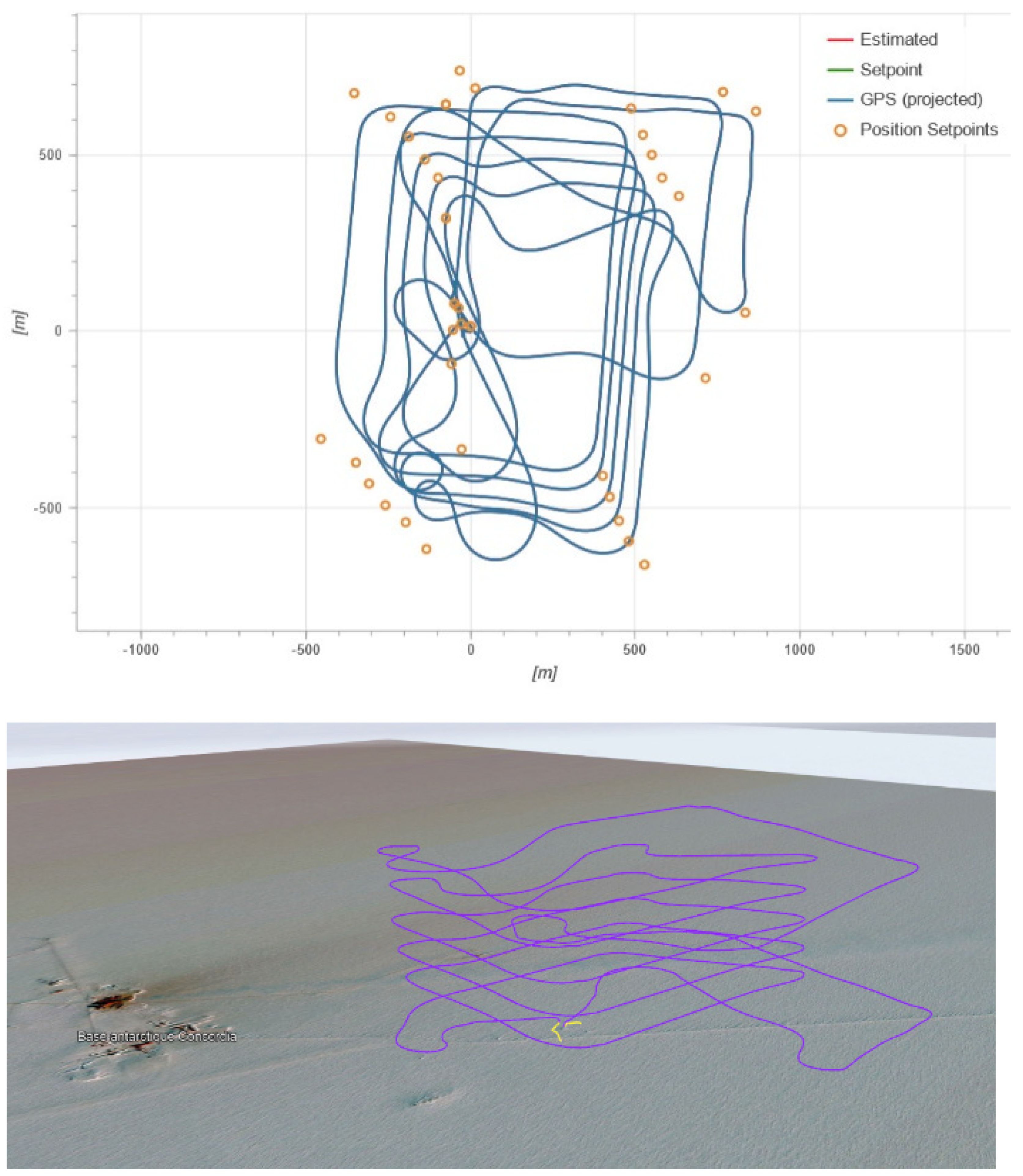
Flight plans must be created before the flight and validated on the company’s website. The drone flights are in the shape of a hippodrome (rectangle with rounded edges) in order to stabilize the payload over a length of about 1000 m (horizontal flight on the long axis of the hippodrome), and then the altitude increases or decreases on the short axis of the hippodrome over a length of about 500 m. The height of the flights could reach 400–600 m above ground level (agl) (about 3600–3800 m altitude). The duration of the flights varied from 20 min (top height reached is 400 m agl) to 30 min (top height reached is 600 m agl). Weekly notices to airmen (NOTAMs) are officially sent to Mario Zucchelli’s station (Italian station on coastal Antarctica) in order to authorize flights in the local afternoon (higher ground temperatures than in the morning) from Monday to Saturday. No flights are possible within a range of −1 h to +4 h around the arrival of an aircraft. The take-off and landing points are set about 2 km north of the Concordia station. We use a skidoo to reach this point. Concretely, 2 people are needed to ensure the drone flights: one focused on the control console and another one in sight of the drone in flight. No flight is made for wind speeds greater than 6 m s−1.
No modification has been made to the drone to take into account the constraints of the site, neither by the company nor by the scientists. In theory, the drone can fly up to 4000 m of altitude for temperatures higher than −20 °C. In addition to the drone and the control console (joystick), a set of spare parts and 2 Lithium Polymer (LiPo) batteries were sent to Concordia. For the payload, pressure, temperature and humidity (PTU) and SLW sondes were also sent to Concordia (see Section 2.2 and Section 2.3).

2.2. Vaisala PTU Sondes

Vertical temperature and humidity profiles have been measured on a daily basis at Dome C since 2005, employing RS92 Vaisala radiosondes. The radiosonde data were taken using the standard Vaisala evaluation routines without any correction of sensor heating or time lag effect. In Antarctica, the sondes are known to have a cold bias of 1.2 K from the ground to about 4 km altitude [20,21] and a dry bias of 4% on integrated water vapor (IWV) [22], mainly between 630 and 470 hPa, with a correction factor for humidity varying within 1.10–1.15 for daytime [23]. All year long, the sondes are attached to a meteorological balloon and launches are performed once per day at 12:00 UTC.
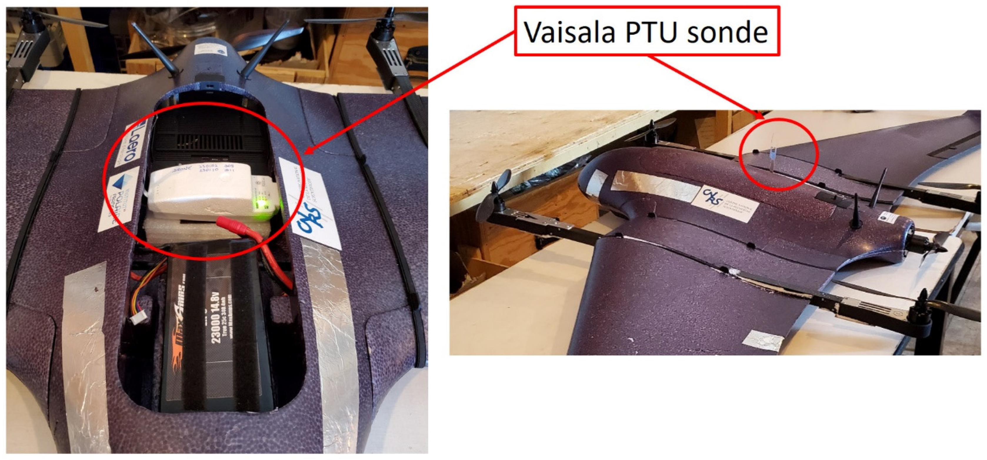
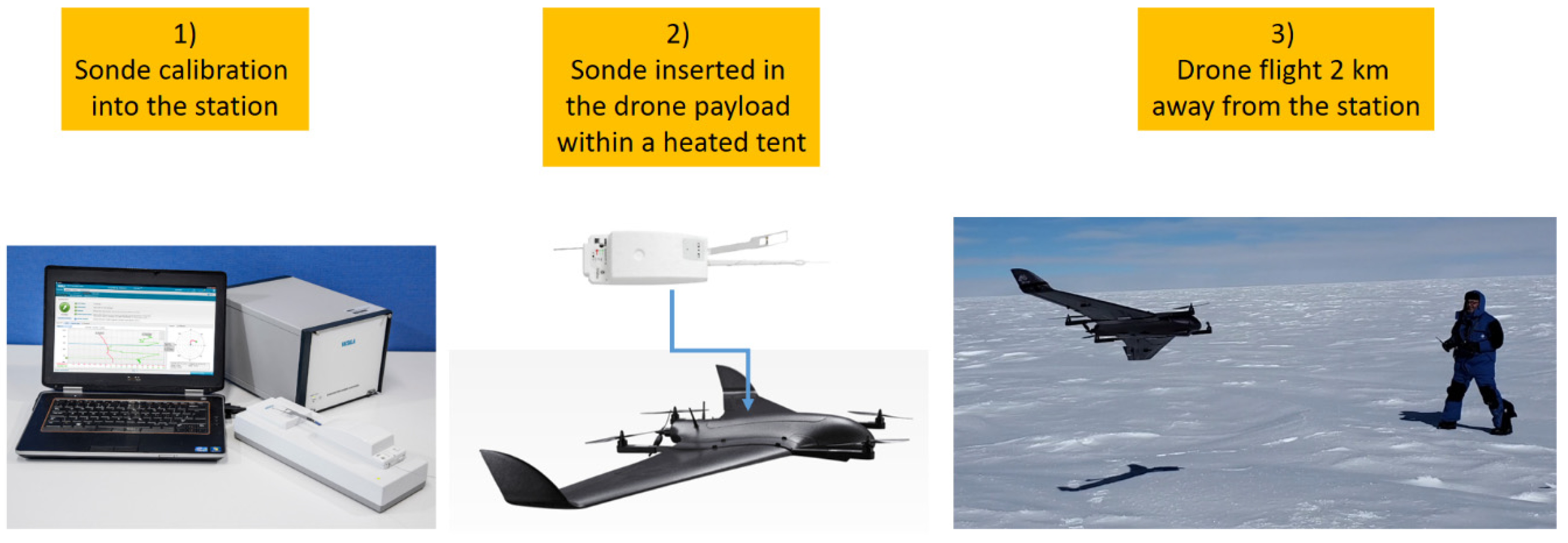
The same Vaisala PTU sondes have been used and installed inside the drone (Figure 2). As when using the sonde attached to the balloons, the sonde has been (1) calibrated inside the station with the Digicora ground station, (2) installed inside the drone within a heated tent at ~500 m away from the station, and (3) the drone was then transported to the take-off area approximately 2000 m away northward from the station using a skidoo (Figure 3). During the flights, the data were transmitted by telemetry and recorded in the same way as for the balloon-borne sondes.

2.3. HAMSTRAD

HAMSTRAD is a microwave radiometer that profiles atmospheric water vapour, liquid water and temperature above Dome C. Measuring at both 60 GHz (oxygen molecule line (O2) to deduce the temperature) and 183 GHz (H2O line), the radiometer developed in 2007 by the RPG-Radiometer Physics GmbH German company under the model name LHATPRO was installed on-site for the first time in January 2009 [24]. The retrieval algorithm is based on a neural network method with a large variety of radiosonde observations all over the year. The same coefficients relying on the brightness temperature to the air temperature have been used since the beginning of the project in 2009. The biases between HAMSTRAD and the sonde are regularly estimated year after year. All the HAMSTRAD data are freely available at the following address: http://www.cnrm.meteo.fr/spip.php?article961&lang=en (accessed on 9 August 2023). The measurements of the HAMSTRAD radiometer allow the retrieval of the vertical profiles from the ground to 10 km agl, with vertical resolutions of 30 to 50 m in the PBL, 100 m in the lower free troposphere and 500 m in the upper troposphere-lower stratosphere. The time resolution has been adjustable and fixed at 60 s since 2018. Note that an automated internal calibration is performed every 12 atmospheric observations and lasts about 4 min. Consequently, the atmospheric time sampling is 60 s for a sequence of 12 profiles and a new sequence starts 4 min after the end of the previous one. The temporal resolution on the instrument allows for the detection and analysis of atmospheric processes such as the diurnal evolution of the PBL [25] and the presence of clouds and diamond dust [26] together with SLWC [12]. In the present analysis, we have only used the vertical profiles of temperature since absolute humidity tends to show positive biases (10–20%) below 1 km agl and negative biases (5–10%) above, while IWV is consistent to within 5% with sonde observations [27].
The biases between HAMSTRAD observations and the operational meteorological sondes have been studied in detail since the installation of the radiometer in 2009 at Concordia [27]. Although the biases changed from one year to another at the beginning of the project, they have been more stable for 4–5 years. They always showed negative biases from 0 to −2 K in the PBL, reaching −2 to −10 K in the free troposphere.

2.4. Numerical Weather Prediction Models

2.4.1. ARPEGE

For this study, the operational French NWP ARPEGE global model has been used [28]. ARPEGE is running operationally in hydrostatic mode. A Turbulent Kinetic Energy (TKE) scheme is used [29] combined with a shallow convection scheme [30]. ARPEGE has a variable mesh with the finest horizontal resolution (5.5 km) over France and lowest resolution over Australia (25 km). A 4D variational (4DVar) assimilation is performed every 6 h. The meteorological analyses were given by the ARPEGE system together with the 24 h forecasts at the node the closest to the location of Dome C. Two analyses at 00:00 and 12:00 UTC were represented in the present study together with hourly forecasts initialized by the two analyses from 01:00 to 11:00 and from 13:00 to 24:00 UTC, respectively. The vertical resolution of the global model ARPEGE is 105 levels. The first one is set at 10 m agl, with 12 levels below 1 km agl and 35 levels below 3 km agl. Temperature and relative humidity were selected for the present analysis.

2.4.2. AROME

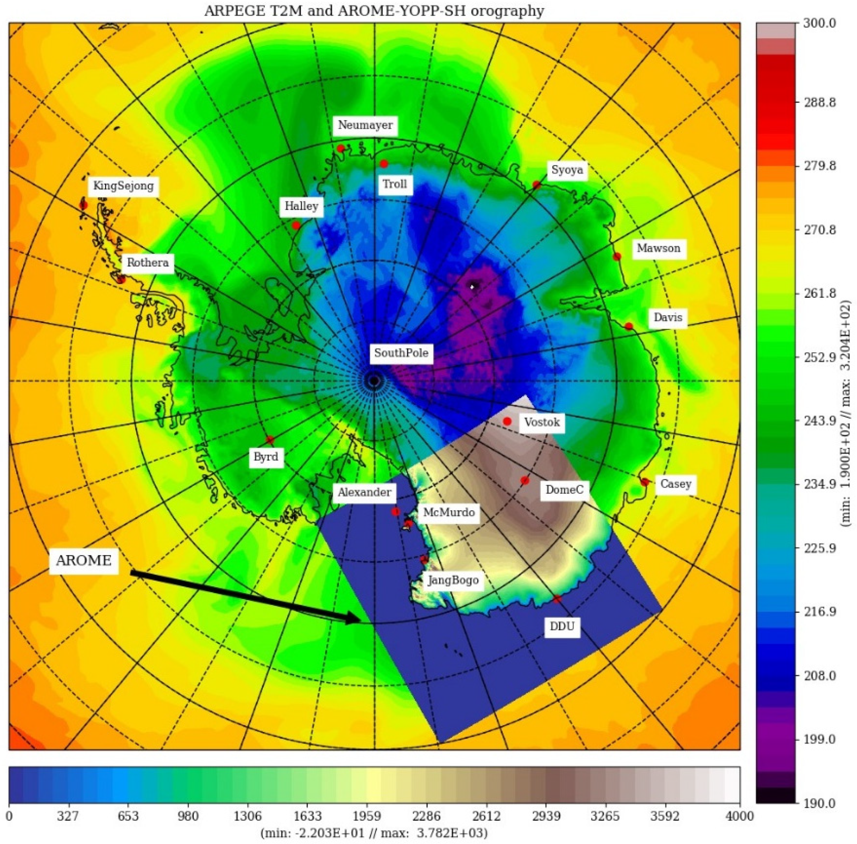
The non-hydrostatic AROME model used for this study is derived from the operational version [31] at 1.3 km horizontal resolution over France, without any specific modification in the atmospheric physics nor in the dynamics, except the coupling with the 1D sea-ice model GELATO, also used in ARPEGE [32]. This experimental system uses exactly the same 90 vertical levels, with the first level at 5 m and a horizontal grid size of 1.5 km. The size of the domain is about 2200 × 2200 km2 in order to cover several super-sites such as Mc Murdo, Dome C and Dumont d’Urville (Figure 4).
The successive ARPEGE analyses obtained at 00:00 UTC provided the initial states for AROME, while the ARPEGE model forecasts provided its lateral boundary conditions. It must be noted that routine radio soundings are made once a day at Dome C, at 12:00 UTC (20:00 local time, LT). This means that the initial states (at 00:00 UTC) of the AROME model never directly benefited from these upper-air observations during the considered period. This avoids an artificial source of positive skill, which would have limited the representativeness of the coupled model results. In the AROME horizontal grid, we selected the point the closest to the Dome C station, namely at a distance of 585.32 m.

2.5. LIDAR

The tropospheric depolarization LIDAR (532 nm) has been operating at Dome C since 2008 (see http://lidarmax.altervista.org/lidar/Antarctic%20LIDAR.php (accessed on 9 August 2023)). The LIDAR provides 5 min tropospheric profiles of aerosols and clouds continuously, from 20 to 7000 m agl, with a resolution of 7.5 m. LIDAR depolarization [33] is a robust indicator of non-spherical shape for randomly oriented cloud particles. A depolarization ratio below 5% is characteristic of SLWC, while values higher than 20% are produced by ice particles. The possible ambiguity between SLWC and oriented ice plates is avoided at Dome C by operating the LIDAR 4° off-zenith [34].

3. Methodology

The initial concept was to install the Vaisala PTU and Anasphere SLW sensors on board the drone, the SLW sensor being connected to the PTU sonde, with a real time data transfer to the Vaisala ground station. Two phases were defined for flying with the drone corresponding to (1) technology flights (no sondes on board) and (2) science flights (sondes on board). Although this was a risky project, we were able to use a drone in this challenging environment and provide scientific results. Thus, 13 flights were conducted from 24 December 2022 to 17 January 2023: 9 technology flights and 4 science flights (Table 2). We have mainly concentrated our study on the four days when scientific flights were successfully performed, namely on 2, 10, 11 and 13 January 2023. Information regarding the speeds (maximum horizontal, up and down speeds, ground speed, height rate and average forward speed) of the drone during the 4 fligths is presented Table 3.
The contamination of the temperature signal by the platform has to be avoided. This problem is particularly important on rotary-wing UAVs [35,36,37,38,39,40]. However, this point is much less crucial on fixed-wing UAVs, such as the platform used in the present study, because of the quite constant relative velocity (the airspeed in our study is about 20 m s−1) that ensures the ventilation of the sensor and prevents it from internal heating. Furthermore, the temperature sensor is at the tip of the radiosonde boom that points upward on the top of the fuselage, so it is away from the skin of the UAV. Temperature sensors were already installed on the top of the fuselage on a fixed-wing drone with a cruise speed similar to that of the present platform by [41]. They demonstrated the relevance of this installation through comparisons with radiosonde profiles. Ref. [15] compared the observations of 38 UAVs (of both fixed-wing and multirotor type) with a reference and reported a larger spread in temperature measurements from multirotors, with a positive bias.
Regarding the effect of solar radiation, the temperature probe was designed by the Vaisala company (https://www.vaisala.com/en (accessed on 9 August 2023)) to minimize its impact mainly thanks to the small size of the sensor. This small size also ensures a response time of the order of 0.4 s at low altitude. Note that a Vaisala RS92 probe was embarked on the Tempest UAS [42].
In the PBL, comparisons of temperature observations between meteorological sondes at 12:00 UTC and drone-borne sondes (06:00–10:00 UTC) might be biased due to the diurnal variation of temperature peaking around 06:00 UTC [25]. Nevertheless, above the PBL, in the free troposphere, the variability of temperature within a maximum of 4 h is meaningful since the temperature variability is within the temperature random error from HAMSTRAD, namely 0.5 K.

4. Results

4.1. Scientific Flight D08 on 2 January 2023

The flight D08 held on 2 January 2023 at 10:00 UTC is the very first flight for which a PTU sonde was aboard the drone. The flight lasted 16 min and reached the maximum height of about 400 m (Figure 5). The flight was nominal over a total distance of 16 km with a surface temperature of −25 °C and a surface wind speed of 2 m s−1.
The vertical profiles of temperature and relative humidity associated with this flight are shown in Figure 6 together with those of the balloon-borne sonde at 12:00 UTC, the HAMSTRAD temperature profile within 09:50–10:10 UTC (in time coincidence with the drone observations), and the outputs from the ARPEGE and the AROME NWP models (at 10:00 UTC). First, the atmosphere on that day shows an abrupt change in both temperature and relative humidity profiles at around 280 m agl associated with an inflection point in the temperature vertical profile and an atmosphere wetter (70–80%) below this height than above (60%). This transition height is associated with the top of the PBL. The balloon-borne radiosonde was launched less than 2 h later and the same behaviour in temperature and relative humidity can be drawn, except that the drone has a much higher vertical resolution than that of the balloon-borne sonde. The HAMSTRAD profile has a worse vertical resolution and is not able to discriminate the two vertical layers in the lowermost troposphere, showing a cold bias of 2–4 °C compared to the drone profile. The atmosphere as calculated by both ARPEGE and AROME tends to be warmer by 1–2 °C and wetter by 10–20% than the atmosphere sounded by the radiosondes with a diurnal variability of 2 °C in temperature and 20% in relative humidity.

4.2. Scientific Flight D11 on 10 January 2023

The second scientific flight D11 held on 10 January 2023 at 06:00 UTC lasted 25 min and reached the maximum height of about 400 m (Figure 7). The flight was nominal over a total distance of 21.5 km with a surface temperature of −25 °C and a surface wind speed at the limit of what can be acceptable at Concordia of 6 m s−1 (wind chill temperature reached about −31 °C). Beyond this value, it was too dangerous to fly with the drone for a sake of stability and for the pilot safety.
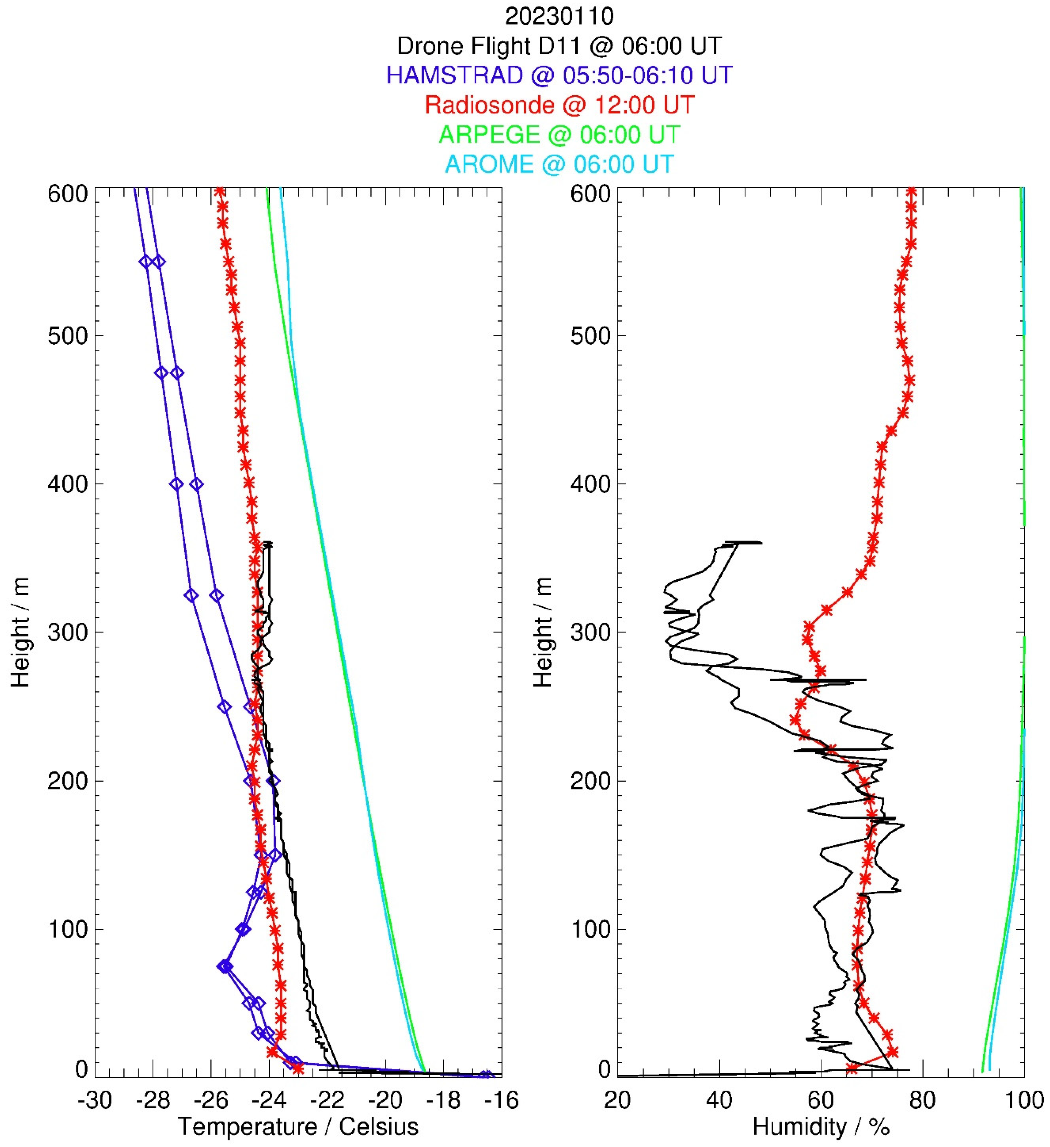
On that date, the in situ drone profiles were showing a lowermost troposphere composed of a wet layer (60–80% relative humidity) below, and a dry layer (30% relative humidity) above around 205–280 m agl where the temperature profile exhibits an inflection point (Figure 8). The ascending and descending profiles are very consistent in temperature, while there is a 5–10% variability in relative humidity that could be explained by an inhomogeneous humidity field encountered by the drone along the 1000 m horizontal legs. The balloon-borne profiles at 12:00 UTC (5 h after the flight) show a lowermost layer consistent with the drone observations for the relative humidity (~70%) but colder by around 1 °C and slightly thinner (around 230 m agl, the level at which the temperature inflection point is observed). The HAMSTRAD temperature values are consistent with the drone profiles between 150 and 250 m agl and systematically colder by 2–4 °C elsewhere. ARPEGE and AROME systematically exhibit a too moist (close to saturation at 90–100%, namely 30–60% more than in situ observations) and too warm (by 2–4 °C) atmosphere with respect to in situ observations.

4.3. Scientific Flight D12 on 11 January 2023

The third scientific flight, D12, held on 11 January 2023 at 06:30 UTC lasted 31 min and reached the maximum height of about 500 m (Figure 9). The flight was nominal over the majority of the path, but the landing was unstable, with a drone reaching the ground only when the battery was close to empty (5% full). The total distance reached during the flight was 21.5 km with a surface temperature of −25 °C and a surface wind speed of 3 m s−1.
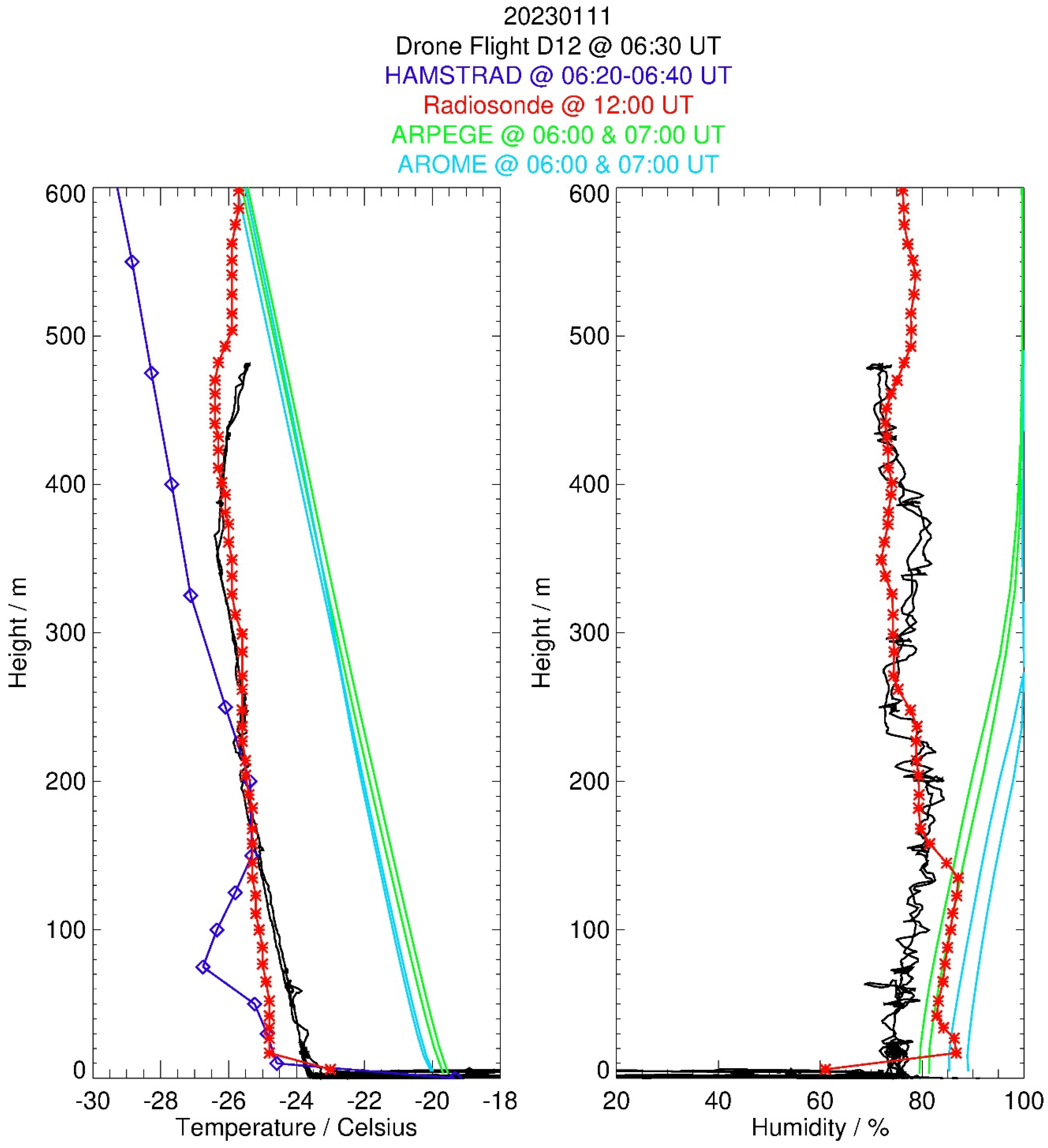
The in situ drone profiles did not show any clear transition between wet and dry layers (relative humidity between 70 and 80%), although two inflection points in the temperature profile were detected at 220 and 370 m agl (Figure 10). The ascending and descending profiles are very consistent with each other. The balloon profile at 12:00 UTC (5:30 h after the flight) is consistent with the drone profile for temperature and relative humidity except below 250 m agl where balloon temperature and relative humidity are less than 0.5 °C and greater than 10% compared to the drone profiles, respectively. The HAMSTRAD temperature values are consistent with the drone profile between 150 and 220 m agl and systematically less by 2–4 °C elsewhere. Again, ARPEGE and AROME systematically exhibit an atmosphere wetter (10–20%) and warmer (2–4 °C) than observed in situ, with AROME slightly wetter (5–10%) and colder (0.2 °C) than ARPEGE.

4.4. Scientific Flight D13 on 13 January 2023

The fourth and last scientific flight, D13, held on 13 January 2023 at 07:30 UTC, lasted 30 min and reached the maximum height of about 600 m (Figure 11), a record height never reached by the drone. The flight was nominal over a total distance of 26.5 km with a surface temperature of −25 °C and a surface wind speed of 3 m s−1.
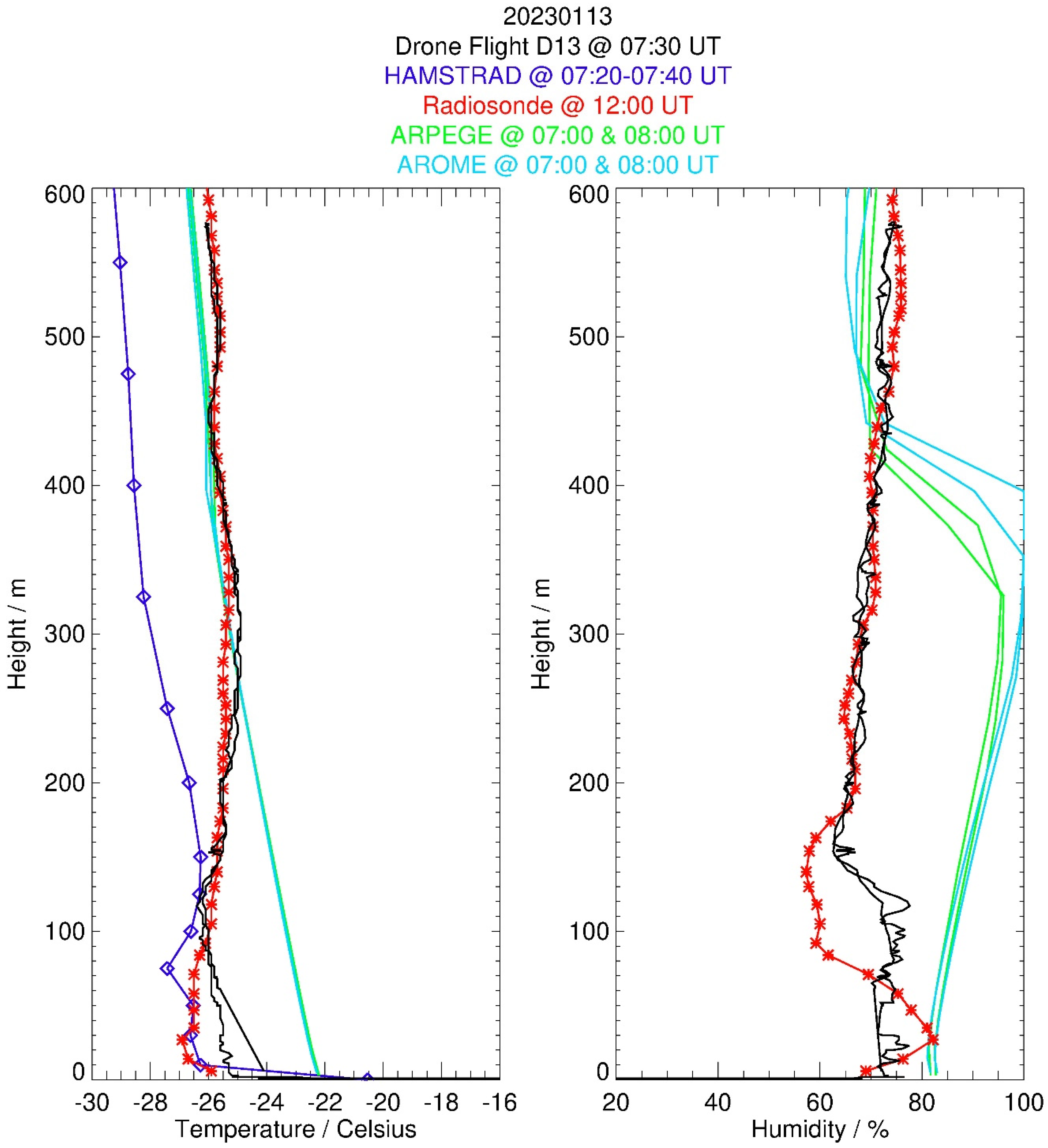
The drone temperature profiles showed an inflection point at 120 m agl with an atmosphere wetter below than above (Figure 12). The ascending and descending profiles are very consistent with each other. The balloon profile at 12:00 UTC (5:30 h after the flight) is very consistent with the drone profile for temperature and relative humidity above 120 m agl. In the lowermost layer, the balloon-borne temperature tends to be less than that of the drone by 1–2 °C, whilst the balloon-borne relative humidity oscillates (within ±10%) around an average value of 70%. The HAMSTRAD temperature profile is systematically less by 2–4 °C than the in situ temperature, except around 120 m agl. ARPEGE and AROME temperatures are consistent with in situ temperatures above 150–120 m agl whereas they are warmer (2–4 °C) below. Below 300–400 m agl, the vertical profiles of relative humidity from ARPEGE and AROME depart from in situ observations by +10–30%, whilst above, an agreement is found to be within ±5%.

5. Discussion

5.1. Drone Operation

The DeltaQuad Pro VTOL drone used at Dome C, Antarctica, provided a good start as a proof of concept for these operations. The VTOL concept was found to be indispensable in these harsh environments. The drone endurance (up to 1 h) was also found to be compatible with horizontal (~1 km)) and vertical (at least 600 m) exploration of the lower troposphere. Note that the PBL thickness does not exceed a few 100 m at Dome C. While the drone design and capabilities have demonstrated their potential in measuring temperature and relative humidity vertical distributions, the performance highlighted several challenges, particularly regarding take-off and landing stability. Despite these difficulties, 4 out of 13 flights yielded scientifically exploitable data. The issues encountered revolved around three main environmental factors: (1) the relatively high altitude (above 3000 m amsl), (2) temperatures less than the minimum of −20 °C for which the drone is rated for, and (3) magnetic instabilities caused by being close to the Earth’s geomagnetic South Pole. To further enhance the drone capabilities and adapt them to the unique conditions encountered in Antarctica, it is essential to understand the factors that contributed to these issues and explore potential improvements.
A significant portion of the take-off and landing instability at Dome C stemmed from the drone’s difficulty in determining its altitude accurately. The extreme cold conditions in Antarctica affected the drone barometer, leading to inaccurate altitude readings and unstable performance. Furthermore, the lack of accurate reference maps made it challenging for the drone to establish its position relative to the terrain, contributing to the instability. Additionally, the drone’s proximity to the Earth’s magnetic poles caused complications in its positioning system, with the magnetometer being particularly affected by its closeness to the poles. These factors collectively contributed to the unstable take-off and landing experienced during the project. Proposed solutions to improve stability in this environment include developing custom reference maps with correct terrain elevations, addressing the barometer issue, and finding a way around the compass issues caused by the location.
For future experiments or if this project was to be conducted again, the DeltaQuad Evo drone model would be a better choice, as it addresses several issues encountered during the previous missions. The DeltaQuad Evo drone has some critical design features that address the issues faced with the DeltaQuad Pro drone. The main points are that the Evo drones have the ability: (1) to not rely on a constant compass bearing once set as this would be reliant on the gyroscope, (2) to use higher quality components with a lower temperature rating, (3) to have a LIDAR mounted under the wing for altitude measurements, and (4) to integrate custom payloads to easily accommodate for a large variety of sensors. The Evo model incorporates folding a landing gear better suited to the Antarctic terrain and features an onboard Real-Time Kinematic (RTK) system that can provide a more accurate compass bearing. With the RTK system, once a compass bearing is set, the drone relies on the gyroscope, eliminating the need for constant magnetometer readings. To mitigate issues caused by extreme cold, a heated barometer could be integrated at the expense of flight time due to the higher power consumption. By implementing these improvements and working collaboratively, the team can enhance the drone’s performance and reliability, ultimately contributing to developing and refining drone technology for various applications in challenging environments like Antarctica.

5.2. Drone Instrumentation

The consistency between ascending and descending profiles is outstanding. This reveals that flight plans and/or sonde performances are well suited for the observation of the vertical profiles. There is no significant lag related to the time response of the probes because this would result in a shift between ascending and descending phases (e.g., on temperature, which presents a stratified profile). We also took advantage of using a PTU sonde that was designed to be operated at the whole range of temperatures observed in the troposphere (i.e., down to approximately −60 °C). There is no freezing issue, nor drifts and/or hysteresis in the signals. With such flight patterns, the profiles are observed with a very fine vertical resolution (a few meters). Horizontal variability can be captured as well with straight and level flight legs.
Temperature sensors were already installed on the top of the fuselage of a fixed-wing drone with a cruise speed similar to that of the present platform by [41]. They demonstrated the relevance of this installation through comparisons with radiosonde profiles. On the other side, the performance of the radiosonde sensors has been widely evaluated worldwide. Under an ascending balloon, the sensors are ventilated with a velocity of around 5 m s−1. Onboard the drone, the ventilation speed reaches about 20 m s−1, which can only improve the performance of the sonde.

5.3. Drone vs. Balloon Profiles

Based on these four scientific flights, from a meteorological point of view, the drone-borne observations were able to probe the PBL with a vertical resolution of at least twice that of the balloon-borne observations because of a height rate about twice as less than that of the balloon’s vertical ascent. Since we were using the same sondes in both balloon and drone flights, the accuracies are similar. The repeatability of the drone flights is paramount for these kinds of observations, depending in first approximation only on the capabilities of the batteries. The other positive point is the fact that the same sonde can be used for several drone flights, which is not the case for balloon flights.
Comparisons between balloon-borne and drone-borne observations showed temperature profiles above ~200 m agl in excellent agreement. At the lowest altitudes, there is sometimes a warmer layer observed by the drone, which is consistent with the delay between the two platforms (in general 5–6 h): the drone flies during the daytime, convective boundary-layer period, whereas the balloon is launched at 08:00 pm LT when the surface has already cooled and the stable surface layer started to develop on surface. For the first flight case, when the time difference between the two platforms is the shortest (2 h), the agreement is excellent.
There is much more variability in the moisture profiles than in temperature profiles, whatever the platform. The colder balloon temperatures are generally coincident with drier layers (in terms of relative humidity). The agreement above, say, at 200 m agl is very good, except on the D11 flight where drone RH values are lower than those from the balloon profile. The advection of an airmass with a different moisture content might be invoked to explain this difference since, on this particular day, the wind was the strongest (6 m s−1 at the surface), and the balloon was released 6 h after the drone flight. To conclude, the consistency of the drone data when compared to the balloon-borne data indicates that there is no perturbation caused by the airplane on the sensors, and the sonde data can be regarded as representative of the sampled atmosphere.

5.4. HAMSTRAD

Comparisons between HAMSTRAD and radiosonde observations reveal that HAMSTRAD profiles exhibit a cold bias of the order of 2 °C. The shape of the individual profiles in the lowest layers (a minimum temperature of around 100 m agl and a maximum of around 200 m agl) appears as an artefact in the retrieval process. This argues in favour of the statistical use of HAMSTRAD profiles in the lowest layers rather than in case studies.
The time-coincident comparisons (not shown) between HAMSTRAD and balloon- and drone-borne sondes do not exhibit any significant differences between the sondes onboard the balloon and the sonde onboard the drone. The highest temperatures observed in the drone-borne sonde compared to the meteorological sondes are attributable in the PBL to the well-known diurnal variation of temperature peaking around 06:00 UTC at Concordia. Above the PBL, no systematic bias is observed between the two sondes. To conclude, by means of HAMSTRAD observations, we have not detected any positive bias in the temperature observed by the sonde inserted close to the battery of the drone compared to the temperature observed by the sonde attached to the meteorological balloons. The harsh environment encountered at Concordia with temperatures much less than −25 °C and the use of a fixed-wing drone compared to a multi-rotor drone lessens the impact of the battery on the temperature observed using the PTU sensor.

5.5. ARPEGE and AROME Models

The ARPEGE and AROME models did not show large differences in temperature and humidity between them despite the fact that AROME is a much higher horizontal resolution model. The Concordia station is situated in the interior of the East Antarctic Plateau, and it is not expected that local phenomena may affect the outputs of the two models, as could be the case on the Antarctic coast and/or in the vicinity of mountains/glaciers (as, e.g., at the stations of Dumont d’Urville and McMurdo). Nevertheless, we observe a net tendency for AROME to calculate an atmosphere slightly moister and colder than ARPEGE. Finally, when compared with observations, the two models showed a lowermost atmosphere systematically warmer and moister despite the fact that the 12:00 UTC operational radiosonde was inserted in the assimilation process of the NWP models. In general, ARPEGE has a warm bias in the PBL in both poles combined with a warm bias on average at the surface. This is a well-known and shared problem in NWP and climate modelling. It is linked with too much low clouds, at least in ARPEGE. AROME uses (1) the initial atmospheric and surface initial conditions from ARPEGE and (2) the ARPEGE lateral boundary conditions. The impact of the horizontal resolution is small in a flat terrain, and the effect of the AROME non-hydrostatic dynamics in Antarctica without strong vertical velocity is negligible. Consequently, we can expect differences between ARPEGE and AROME through the shallow convection, but this is not very active in such harsh conditions as the ones encountered over the Antarctic Plateau and through the microphysics scheme mainly tuned for convective events in mid-latitudes.

5.6. Clear Sky Conditions

In order to assess whether the drone was actually flying in clear sky conditions, we present Figure 13, the time evolution of the backscattering ratio observed by the LIDAR installed at Concordia (arbitrary unit, top) and the depolarization ratio observed by the LIDAR (%, bottom) on 2, 10, 11 and 13 January 2023. Low depolarization (<5%) highlights SLWCs, whilst high depolarization (>20%) shows ice (crystals) clouds. On 2 and 11 January 2023, it is obvious that LIDAR observations show no cloud nor precipitation below 500 m agl during the drone flight (10:00–10:15 UTC on 2 January and 06:30–07:00 UTC on 11 January) and the operational sonde launch at 12:00 UTC. So, the study can be labelled as having clear sky conditions for these two dates.
On 10 January 2023, the drone flight below 400 m agl at 06:00–06:30 UTC did not encounter any cloud, but the operational sonde at 12:00 UTC launched within solid precipitation (depolarization ratio greater than 30%). This possibly explains the greater (~30%) relative humidity around 300 m agl in the operational sonde compared to the drone-borne sonde. However, again, on 10 January, the drone flew in clear sky conditions.
On 13 January 2023, the drone flight below 600 m agl at 07:30–08:00 UTC did not encounter any cloud nor precipitation, although the operational sonde at 12:00 UTC has been launched within solid precipitation conditions (depolarization ratio ranging 20–30% from the surface to 1000 m agl, namely ice crystals). Nevertheless, the impact on the relative humidity operational profile is rather weak compared to the drone-borne profile: ±10% below 200 m agl.
To conclude, the four drone flights were achieved in clear-sky conditions. The operational sonde was also launched in clear-sky conditions on 2 and 11 January, whilst solid precipitation occurred on 10 and 13 January. Nevertheless, the difference in relative humidity between drone-borne and balloon-borne sondes is, in general, within ±10%, except on 10 January, when it reached 20% at 300 m agl.

6. Conclusions

The present project was based on the original idea to probe in situ the lowermost atmosphere above Dome C, Antarctica, by means of a drone in order to study the distributions (horizontal and vertical) of SLWCs. This challenging idea relied on the use of a standard vertical take-off and landing drone with two kinds of sonde on board: one dedicated to the observations of pressure, temperature and relative humidity (standard Vaisala PTU sondes) and another one sensitive to SLW (sonde developed by the Anasphere Company). Unfortunately, we were not able to perform in situ observations of SLWCs because (1) the drone crashed before the SLW sonde was coupled to the PTU sonde, and (2) during the 2022–2023 summer campaign, no SLW clouds were observed for a time period longer than 2 h. The drone was actually operated outside or in the vicinity of the tolerances highlighted by the DeltaQuad Company with temperatures less than −20 °C, close to the geomagnetic pole and to the maximum altitude of 4000 m amsl. Nevertheless, within this harsh environment, the drone flew thirteen times, nine with no payload (technological flights) and four with a PTU sonde onboard (scientific flights). We were able to analyse these four scientific flights giving original in situ observations of temperature and relative humidity from the surface to a maximum height of 600 m agl to be compared with balloon-borne observations, ground-based microwave radiometer measurements and the outputs from two NWP models (ARPEGE and AROME).
The quality of the drone-based observations was very high, with no visible impact of the drone flight onto the vertical profiles of temperature and relative humidity. With a vertical resolution of a few meters, the drone-borne profiles were very consistent with the balloon-borne profiles both in temperature and relative humidity despite some time difference from 2 to 6 h, except in the very low atmospheric layers (inside the PBL) where the temperature and relative humidity diurnal variations are significant. On average, the temperature profiles from HAMSTRAD showed an atmosphere colder than the drone-based observations by 2 °C. The two model outputs exhibited similar results, although AROME had a much better horizontal resolution compared to ARPEGE, with an atmosphere warmer (by 2–4 °C) and moister (by 10–30%) than the drone-based observations in the PBL.
These encouraging results tend to show that probing the atmosphere of the Eastern Antarctic plateau with a drone, although challenging, is possible and can provide unique observations. In the near future, we would still like to observe SLWCs in situ. In order to achieve this task, we will need to update the drone we have used in different directions: (1) a folding landing gear better suited to the Antarctic terrain, (2) onboard RTK system to obtain a more accurate compass bearing, (3) a heated barometer to mitigate issues caused by extreme cold, and (4) insert another LiPo battery to cope with a higher power consumption without diminishing the flight time associated with the excess of mass.

Author Contributions

P.R., P.G. and M.D.G. provided the observational data. E.B. provided the model data. P.R. developed the methodology. All the co-authors participated in the data analysis and in the data interpretation. P.R. prepared the manuscript with contributions from all co-authors. All authors have read and agreed to the published version of the manuscript.

Funding

The HAMSTRAD programme 910 and the SLW-CLOUDS programme 1247 were supported by the French Polar Institute, Institut polaire français Paul-Emile Victor (IPEV), the Institut National des Sciences de l’Univers (INSU)/Centre National de la Recherche Scientifique (CNRS), Météo-France and the Centre National d’Etudes Spatiales (CNES).

Data Availability Statement

HAMSTRAD data are available at: http://www.cnrm.meteo.fr/spip.php?article961&lang=en (last access: 9 August 2023). Radiosondes are available at http://www.climantartide.it (last access: 9 August 2023). Lidar data are available at http://lidarmax.altervista.org/lidar/Antarctic%20LIDAR.php (last access: 9 August 2023).

Acknowledgments

The present research project Water Budget over Dome C (H2O-DC) has been approved by the Year of Polar Prediction (YOPP) international committee. The permanently manned Concordia station is jointly operated by IPEV and the Italian Programma Nazionale Ricerche in Antartide (PNRA). The tropospheric LIDAR has operated at Dome C since 2008 within the framework of several Italian national (PNRA) projects. We would like to thank all the winterover personnel who worked at Dome C on the different projects: HAMSTRAD, operational meteorological soundings, in situ balloon-borne and drone-based observations, and the aerosol LIDAR. Special thanks to Armand Patoir (IPEV) for his valuable work on the drone repairs. Finally, we would like to thank the three anonymous reviewers for their beneficial comments.

Conflicts of Interest

The authors declare that they have no conflict of interest.

References

  1. Lubin, D.; Chen, B.; Bromwich, D.H.; Somerville, R.C.; Lee, W.H.; Hines, K.M. The Impact of Antarctic Cloud Radiative Properties on a GCM Climate Simulation. J. Clim. 1998, 11, 447–462. [Google Scholar] [CrossRef]
  2. Bromwich, D.H.; Nicolas, J.P.; Hines, K.M.; Kay, J.E.; Key, E.L.; Lazzara Lubin, D.; McFarquhar, G.M.; Gorodetskaya, I.V.; Grosvenor, D.P.; Lachlan-Cope, T.; et al. Tropospheric clouds in Antarctica. Rev. Geophys. 2012, 50, RG1004. [Google Scholar] [CrossRef] [Green Version]
  3. Lachlan-Cope, T. Antarctic clouds. Polar Res. 2010, 29, 150–158. [Google Scholar] [CrossRef]
  4. Grosvenor, D.P.; Choularton, T.W.; Lachlan-Cope, T.; Gallagher, M.W.; Crosier, J.; Bower, K.N.; Ladkin, R.S.; Dorsey, J.R. In-situ aircraft observations of ice concentrations within clouds over the Antarctic Peninsula and Larsen Ice Shelf. Atmos. Chem. Phys. 2012, 12, 11275–11294. [Google Scholar] [CrossRef] [Green Version]
  5. Lachlan-Cope, T.; Listowski, C.; O’Shea, S. The microphysics of clouds over the Antarctic Peninsula—Part 1: Observations. Atmos. Chem. Phys. 2016, 16, 15605–15617. [Google Scholar] [CrossRef] [Green Version]
  6. Grazioli, J.; Genthon, C.; Boudevillain, B.; Duran-Alarcon, C.; Del Guasta, M.; Madeleine, J.-B.; Berne, A. Measurements of precipitation in Dumont d’Urville, Adélie Land, East Antarctica. Cryosphere 2017, 11, 1797–1811. [Google Scholar] [CrossRef] [Green Version]
  7. O’Shea, S.J.; Choularton, T.W.; Flynn, M.; Bower, K.N.; Gallagher, M.; Crosier, J.; Williams, P.; Crawford, I.; Fleming, Z.L.; Listowski, C.; et al. In situ measurements of cloud microphysics and aerosol over coastal Antarctica during the MAC campaign. Atmos. Chem. Phys. 2017, 17, 13049–13070. [Google Scholar] [CrossRef] [Green Version]
  8. Listowski, C.; Delanoë, J.; Kirchgaessner, A.; Lachlan-Cope, T.; King, J. Antarctic clouds, supercooled liquid water and mixed phase, investigated with DARDAR: Geographical and seasonal variations. Atmos. Chem. Phys. 2019, 19, 6771–6808. [Google Scholar] [CrossRef] [Green Version]
  9. King, J.C.; Argentini, S.A.; Anderson, P.S. Contrasts between the summertime surface energy balance and boundary layer structure at Dome C and Halley stations, Antarctica. J. Geophys. Res. Atmos. 2006, 111, D02105. [Google Scholar] [CrossRef]
  10. King, J.C.; Gadian, A.; Kirchgaessner, A.; Kuipers Munneke, P.; Lachlan-Cope, T.A.; Orr, A.; Reijmer, C.; Broeke, M.R.; van Wessem, J.M.; Weeks, M. Validation of the summertime surface energy budget of Larsen C Ice Shelf (Antarctica) as represented in three high-resolution atmospheric models. J. Geophys. Res. Atmos. 2015, 120, 1335–1347. [Google Scholar] [CrossRef] [Green Version]
  11. Lawson, R.P.; Gettelman, A. Impact of Antarctic mixed-phase clouds on climate. Proc. Natl. Acad. Sci. USA 2014, 111, 18156–18161. [Google Scholar] [CrossRef] [PubMed]
  12. Ricaud, P.; Del Guasta, M.; Bazile, E.; Azouz, N.; Lupi, A.; Durand, P.; Attié, J.-L.; Veron, D.; Guidard, V.; Grigioni, P. Supercooled liquid water cloud observed, analysed, and modelled at the top of the planetary boundary layer above Dome C, Antarctica. Atmos. Chem. Phys. 2020, 20, 4167–4191. [Google Scholar] [CrossRef] [Green Version]
  13. Ricaud, P.; Del Guasta, M.; Lupi, A.; Roehrig, R.; Bazile, E.; Durand, P.; Attié, J.L.; Nicosia, A.; Grigioni, P. Supercooled liquid water clouds observed over Dome C, Antarctica: Temperature sensitivity and surface radiation impact. Atmos. Chem. Phys. Discuss. 2022, 1–38. [Google Scholar] [CrossRef]
  14. Leuenberger, D.; Haefele, A.; Omanovic, N.; Fengler, M.; Martucci, G.; Calpini, B.; Fuhrer, O.; Rossa, A. Improving high-impact Numerical Weather Prediction with lidar and drone observations. Bull. Am. Meteorol. Soc. 2020, 101, E1036–E1051. [Google Scholar] [CrossRef] [Green Version]
  15. Barbieri, L.; Kral, S.T.; Bailey, S.C.; Frazier, A.E.; Jacob, J.D.; Reuder, J.; Brus, D.; Chilson, P.B.; Crick, C.; Detweiler, C.; et al. Intercomparison of small unmanned aircraft system (sUAS) measurements for atmospheric science during the LAPSE-RATE campaign. Sensors 2019, 19, 2179. [Google Scholar] [CrossRef] [Green Version]
  16. Tovar-Sánchez, A.; Román, A.; Roque-Atienza, D.; Navarro, G. Applications of unmanned aerial vehicles in Antarctic environmental research. Sci. Rep. 2021, 11, 21717. [Google Scholar] [CrossRef]
  17. Pina, P.; Vieira, G. UAVs for science in Antarctica. Remote Sens. 2022, 14, 1610. [Google Scholar] [CrossRef]
  18. Alaoui-Sosse, S.; Durand, P.; Medina, P.; Pastor, P.; Gavart, M.; Pizziol, S. BOREAL—A fixed-wing unmanned aerial system for the measurement of wind and turbulence in the atmospheric boundary layer. J. Atmos. Ocean. Tech. 2022, 39, 387–402. [Google Scholar] [CrossRef]
  19. Serke, D.; Hall, E.; Bognar, J.; Jordan, A.; Abdo, S.; Baker, K.; Seitel, T.; Nelson, M.; Ware, R.; McDonough, F.; et al. Supercooled liquid water content profiling case studies with a new vibrating wire sonde compared to a ground-based microwave radiometer. Atmos. Res. 2014, 149, 77–87. [Google Scholar] [CrossRef] [Green Version]
  20. Tomasi, C.; Petkov, B.; Benedetti, E.; Valenziano, L.; Vitale, V. Analysis of a 4 year radiosonde dataset at Dome C for characterizing temperature and moisture conditions of the Antarctic atmosphere. J. Geophys. Res. 2011, 116, D15304. [Google Scholar] [CrossRef] [Green Version]
  21. Tomasi, C.; Petkov, B.H.; Benedetti, E. Annual cycles of pressure, temperature, absolute humidity and precipitable water from the radiosoundings performed at Dome C, Antarctica, over the 2005–2009 period. Antarct. Sci. 2012, 24, 637–658. [Google Scholar] [CrossRef]
  22. Miloshevich, L.M.; Vömel, H.; Whiteman, D.N.; Lesht, B.M.; Schmidlin, F.J.; Russo, F. Absolute accuracy of water vapor measurements from six operational radiosonde types launched during AWEX-G and implications for AIRS validation. J. Geophys. Res. 2006, 111, D09S10. [Google Scholar] [CrossRef] [Green Version]
  23. Miloshevich, L.M.; Vömel, H.; Whiteman, D.N.; Leblanc, T. Accuracy assessment and corrections of Vaisala RS92 radiosonde water vapour measurements. J. Geophys. Res. 2009, 114, D11305. [Google Scholar] [CrossRef] [Green Version]
  24. Ricaud, P.; Gabard, B.; Derrien, S.; Chaboureau, J.-P.; Rose, T.; Mombauer, A.; Czekala, H. HAMSTRAD-Tropo, A 183-GHz Radiometer Dedicated to Sound Tropospheric Water Vapor Over Concordia Station, Antarctica. IEEE Trans. Geosci. Remote Sens. 2010, 48, 1365–1380. [Google Scholar] [CrossRef]
  25. Ricaud, P.; Genthon, C.; Durand, P.; Attié, J.-L.; Carminati, F.; Canut, G.; Vanacker, J.-F.; Moggio, L.; Courcoux, Y.; Pellegrini, A.; et al. Summer to Winter Diurnal Variabilities of Temperature and Water Vapor in the lowermost troposphere as observed by the HAMSTRAD Radiometer over Dome C, Antarctica. Bound. Lay. Meteorol. 2012, 143, 227–259. [Google Scholar] [CrossRef]
  26. Ricaud, P.; Bazile, E.; del Guasta, M.; Lanconelli, C.; Grigioni, P.; Mahjoub, A. Genesis of diamond dust, ice fog and thick cloud episodes observed and modelled above Dome C, Antarctica. Atmos. Chem. Phys. 2017, 17, 5221–5237. [Google Scholar] [CrossRef] [Green Version]
  27. Ricaud, P.; Grigioni, P.; Zbinden, R.; Attié, J.-L.; Genoni, L.; Galeandro, A.; Moggio, L.; Montaguti, S.; Petenko, I.; Legovini, P. Review of Tropospheric Temperature, Absolute Humidity and Integrated Water Vapour from the HAMSTRAD Radiometer installed at Dome C (Antarctica) over the period 2009–2014. Antarct. Sci. 2015, 27, 598–616. [Google Scholar] [CrossRef] [Green Version]
  28. Pailleux, J.; Geleyn, J.-F.; El Khatib, R.; Fischer, C.; Hamrud, M.; Thépaut, J.-N.; Rabier, F.; Andersson, E.; Salmond, D.; Burridge, D.; et al. Les 25 ans du système de prévision numérique du temps IFS/Arpège. Météorologie 2015, 89, 18–27. [Google Scholar] [CrossRef] [Green Version]
  29. Cuxart, J.; Bougeault, P.; Redelsperger, J.-L. A turbulence scheme allowing for mesoscale and large-eddy simulations. Q. J. R. Meteorol. Soc. 2000, 126, 1–30. [Google Scholar] [CrossRef]
  30. Bazile, E.; Marquet, P.; Bouteloup, Y.; Bouyssel, F. The turbulent kinetic energy (TKE) scheme in the NWP models at Météo-France. In Proceedings of the Workshop on Diurnal Cycles and the Stable Boundary Layer, ECMWF, Reading, UK, 7–10 November 2011; pp. 127–136. [Google Scholar]
  31. Seity, Y.; Brousseau, P.; Malardel, S.; Hello, G.; Bénard, P.; Bouttier, F.; Lac, C.; Masson, V. The AROME-France convective-scale operational model. Mon. Weather. Rev. 2011, 139, 976–991. [Google Scholar] [CrossRef] [Green Version]
  32. Bazile, E.; Azouz, N.; Napoly, A.; Loo, C. Impact of the 1D sea-ice model GELATO in the global model ARPEGE. WCRP Rep. 12/2020. Res. Act. Earth Syst. Model. Rep. 2020, 50, 2. [Google Scholar]
  33. Mishchenko, M.I.; Hovenier, J.W.; Travis, L.D. (Eds.) Light Scattering by Nonspherical Particles: Theory, Measurements, and Applications; Academic Press: Cambridge, MA, USA, 2000; Volume 14, pp. 393–416. [Google Scholar]
  34. Hogan, R.J.; Illingworth, A.J. The Effect of Specular Reflection on Spaceborne Lidar Measurements of Ice Clouds. Rep. ESA Retr. Algorithm EarthCARE Proj. 2003, 5. [Google Scholar]
  35. Greene, B.R.; Segales, A.R.; Waugh, S.; Duthoit, S.; Chilson, P.B. Considerations for temperature sensor placement on rotarywing unmanned aircraft systems. Atmos. Meas. Tech. 2018, 11, 5519–5530. [Google Scholar] [CrossRef] [Green Version]
  36. Greene, B.R.; Segales, A.R.; Bell, T.M.; Pillar-Little, E.A.; Chilson, P.B. Environmental and sensor integration influences on temperature measurements by rotary-wing unmanned aircraft systems. Sensors 2019, 19, 1470. [Google Scholar] [CrossRef] [Green Version]
  37. Lee, T.R.; Buban, M.; Dumas, E.; Baker, C.B. On the use of rotary-wing aircraft to sample near-surface thermodynamic fields: Results from recent field campaigns. Sensors 2019, 19, 10. [Google Scholar] [CrossRef] [Green Version]
  38. Kimball, S.K.; Montalvo, C.J.; Mulekar, M.S. Assessing iMET-XQ performance and optimal placement on a small off-the-shelf, Rotary-Wing UAV, as a Function of Atmospheric Conditions. Atmosphere 2020, 11, 660. [Google Scholar] [CrossRef]
  39. Inoue, J.; Sato, K. Toward sustainable meteorological profiling in polar regions: Case studies using an inexpensive UAS on measuring lower boundary layers with quality of radiosondes. Env. Res. 2022, 205, 112468. [Google Scholar] [CrossRef]
  40. Inoue, J.; Sato, K. Wind speed measurement by an inexpensive and lightweight thermal anemometer on a small UAV. Drones 2022, 6, 289. [Google Scholar] [CrossRef]
  41. Alaoui-Sosse, S.; Durand, P.; Medina, P.; Pastor, P.; Lothon, M.; Cernov, I. OVLI-TA: An unmanned aerial system for measuring profiles and turbulence in the atmospheric boundary layer. Sensors 2019, 19, 581. [Google Scholar] [CrossRef] [Green Version]
  42. Elston, J.S.; Roadman, J.; Stachura, M.; Argrow, B.; Houston, A.; Frew, E. The tempest unmanned aircraft system for in situ observations of tornadic supercells: Design and VORTEX2 flight results. J. Field Robot. 2011, 28, 461–483. [Google Scholar] [CrossRef]
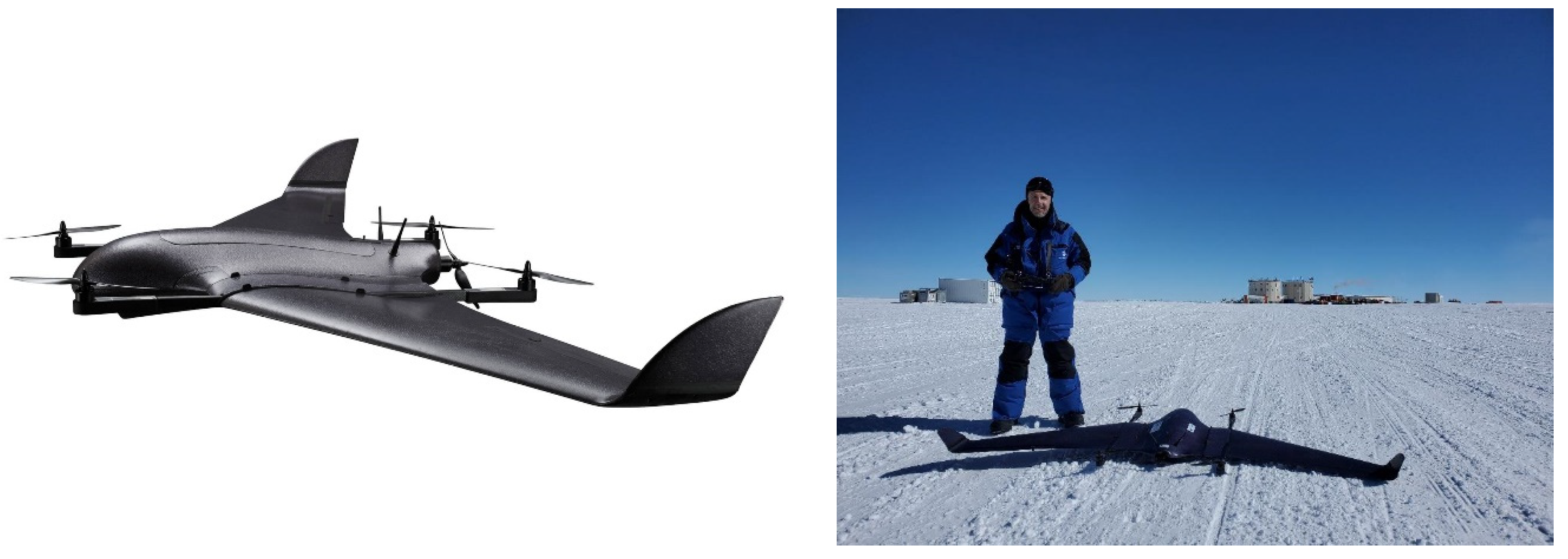
Figure 1. (Left) The VTOL drone from the DeltaQuad Company. (Right) The drone laying on the ground at the Concordia Station during the summer campaign 2022–23.
Drones 07 00532 g001
Figure 2. The Vaisala PTU sonde inserted into the drone before a scientific flight at the Concordia station during the summer campaign 2022–23: (left) inside the payload dedicated area and (right) prior to the launch with only the temperature and relative humidity sensor upward outside of the drone. Note the telemetry antenna is located beneath the drone (not visible in the picture).
Drones 07 00532 g002
Figure 3. The methodology used for the scientific flights is synthetized as follows. (1) The Vaisala PTU sondes are calibrated into the quiet building of the Concordia station at room temperature using the standard Digicora system. (2) The PTU sonde is then transported to a heated tent about 500 m away from the station where the drone is stored. Then, the sonde is installed inside the drone. (3) The drone is transported with a skidoo to about 2 km away from the heated tent in the northward direction. There, it is launched following a previously validated flight plan.
Drones 07 00532 g003
Figure 4. Horizontal domain where the AROME model is run within the large domain where ARPEGE is run together with the sites where the outputs are regularly stored. Note the color scale is not meaningful.
Drones 07 00532 g004
Figure 5. (Top) Hippodrome flight plan (blue line) corresponding to the flight D08 on 2 January 2023 up to 400 m high. The x-axis points towards the East whilst the y-axis points towards the North. In the climbing phase, the N-S runs are performed at a levelled height whilst during the W-E runs the height is increased by 50 m. In the descending phase, the drone flies down on all the straight runs. Note that the blue line is superimposed on the red and green lines. (Bottom) Three-dimensional view of the drone flight (purple line) based on the Keyhole Markup Language (KML) file with the Concordia station at the extreme left. The yellow line represents the ascending part of the vertical take-off phase when the drone is in multirotor mode.
Drones 07 00532 g005aDrones 07 00532 g005b
Figure 6. Vertical profiles of temperature (left, °C) and relative humidity (right, %) measured by the Vaisala sonde onboard the drone during the ascending and descending flight phases for the flight D08 on 2 January 2023 around 10:00 UTC (black) and as observed by the balloon-borne sonde at 12:00 UTC (red). The HAMSTRAD temperature measurements within 09:50–10:10 UTC are also shown in purple (left). The ARPEGE and AROME profiles calculated at 10:00 UTC are displayed in green and blue, respectively.
Drones 07 00532 g006
Figure 7. Same as Figure 5 but for the flight D11 on 10 January 2023 at 06:00 UTC up to 400 m high.
Drones 07 00532 g007
Figure 8. Same as Figure 6 but for the flight D11 on 2 January 2023 at 06:00 UTC (black) and as observed by the balloon-borne sonde at 12:00 UTC (red). The HAMSTRAD temperature measurements within 05:50–06:10 UTC are also shown in purple (left). The ARPEGE and AROME profiles calculated at 06:00 UTC are displayed in green and blue, respectively.
Drones 07 00532 g008
Figure 9. Same as Figure 5 but for the flight D12 on 11 January 2023 at 06:30 UTC up to 500 m high.
Drones 07 00532 g009
Figure 10. Same as Figure 6 but for flight D12 on 11 January 2023 at 06:30 UTC (black) and as observed by the balloon-borne sonde at 12:00 UTC (red). The HAMSTRAD temperature profile within 06:20–06:40 UTC is also shown in purple (left). The ARPEGE and AROME profiles calculated at 06:00 and 07:00 UTC are displayed in green and blue, respectively.
Drones 07 00532 g010
Figure 11. Same as Figure 5 but for the flight D13 on 13 January 2023 at 07:30 UTC up to 600 m high.
Drones 07 00532 g011
Figure 12. Same as Figure 6 but for the flight D13 on 13 January 2023 at 07:30 UTC (black) and as observed by the balloon-borne sonde at 12:00 UTC (red). The HAMSTRAD temperature measurement within 07:20–07:40 UTC is also shown in purple (left). The ARPEGE and AROME profiles calculated at 07:00 and 08:00 UTC are displayed in green and blue, respectively.
Drones 07 00532 g012
Figure 13. Time evolution of logarithm of the backscattering ratio observed by the LIDAR installed at Concordia (arbitrary unit, top) and depolarization ratio observed by the LIDAR (%, bottom) on 2 January (top left), 10 January (top right), 11 January (bottom left) and 13 January 2023 (bottom right). The time and the vertical ranges associated with the drone-borne observations are highlighted by a purple rectangle, whilst the meteorological operational balloon-borne observations at 12:00 UTC are shown as a black line. Note that a white color symbolizes no data (no observation or no signal detected). A reddish color in log(signal) symbolizes a cloud and/or precipitation and when associated with a low depolarization (<5%), water is in liquid form, whilst for high depolarization (>20%), water is in solid (crystals) form.
Drones 07 00532 g013
Table 1. Technical characteristics of the VTOL drone used at Concordia.
Dimensions
Wingspan235 cm
Length90 cm
Height17 cm
Weight and Payload
Empty weight3.3 kg
Empty weight including battery5 kg
Maximum takeoff weight6.2 kg
Payload capacity1.2 kg
Flight Characteristics at max payload
Cruise speed16 m/s (60 km/h)
Maximum speed25 m/s (90 km/h)
Maximum flight time1 h 50 min
Range through air100 km
Power
Battery typeLiPo
Battery capacity23 Ah
Tolerances
Maximum takeoff/landing wind9 m/s (33 km/h)
Maximum wind cruise flight14 m/s (50 km/h)
Operating temperatureBetween −20 and +45 Celsius
Maximum flight altitude amsl13,000 ft (4000 m)
Table 2. List of all the flights performed with the drone during the 2022–2023 summer over Concordia, together with the date, time (UTC), Scientific or Technological flight (S/T) category, status of the flight (G: good; U-TO: unsatisfactory take-off; C-TO: crash at take-off; C-La: crash at landing; C-Fly: crash when flying), maximum height reached (m), duration of the flight (minutes), distance covered (km), surface wind (m s−1) and surface temperature (Celsius). Note that flights D01 and D02 were performed in France. In green are the flights scientifically exploitable.
Flight
#
Date
YYMMDD
Time
HH:MM
UTC
S/T
Flight
RatingMax
Height
m
Duration
Minutes
Distance
km
Surface
Wind
m s−1
Surface
T
° Celsius
D0322122403:00TG60432−30
D0422122707:00TU-TO20076.25−30
D0522122806:30TC-TO 5−30
D0622122807:00TU-TO2001283−25
D0723010206:30TG2001282−25
D0823010210:00SG40016152−25
D0923010310:00SC-TO 2−25
D1023010906:00TG2001493−25
D1123011006:00SG4002521.56−25
D1223011106:30SG/C-La50031253−25
D1323011307:30SG6003026.53−25
D1423011609:30SC-TO 5−25
D1523011707:00SC-Fly 5−30
Table 3. Speeds (m s−1) associated with the 4 flights held on 2, 10, 11 and 13 January 2023: maximum horizontal, up and down speeds, ground speed, height rate and average forward speed.
Speed/m s−1D08
2 January
D11
10 January
D12
11 January
D13
13 January
Max Speed Horizontal27332828
Max Speed Up3434
Max Speed Down6665
Ground Speed25322827
Height Rate2222
Average Speed FW23202120
Disclaimer/Publisher’s Note: The statements, opinions and data contained in all publications are solely those of the individual author(s) and contributor(s) and not of MDPI and/or the editor(s). MDPI and/or the editor(s) disclaim responsibility for any injury to people or property resulting from any ideas, methods, instructions or products referred to in the content.