Article

Towards the Designing of Low-Latency SAGIN: Ground-to-UAV Communications over Interference Channel

School of Systems and Enterprises, Stevens Institute of Technology, Hoboken, NJ 07030, USA
*
Author to whom correspondence should be addressed.
These authors contributed equally to this work.
Drones 2023, 7(7), 479; https://doi.org/10.3390/drones7070479
Submission received: 30 June 2023 / Revised: 16 July 2023 / Accepted: 18 July 2023 / Published: 20 July 2023
(This article belongs to the Special Issue UAVs Communications for 6G)

Abstract

:
We present a novel and first-of-its-kind information-theoretic framework for the key design consideration and implementation of a ground-to-unmanned Aerial Vehicle (UAV) (G2U) communication network with an aim to minimize end-to-end transmission delay in the presence of interference in Space-Air-Ground Integrated Networks (SAGIN). To characterize the transmission delay, we utilize Fano’s inequality and derive the tight upper bound for the capacity for the G2U uplink channel in the presence of interference, noise, and potential jamming. In addition, as a function of the location information of the UAV, a tight lower bound on the transmit power is obtained subject to the reliability constraint and the maximum delay threshold. Furthermore, a relay UAV in the dual-hop relay mode, with amplify-and-forward (AF) protocol, is considered, for which we jointly obtain the optimal positions of the relay and the receiver UAVs in the presence of interference, with straight-line, circular, and helical trajectories as UAV tracing. Interestingly, increasing the power gives a negligible gain in terms of delay minimization, though may greatly enhance the outage performance. Moreover, we prove that there exists an optimal height that minimizes the end-to-end transmission delay in the presence of interference. We show the interesting result of the delay analysis. In particular, it is shown that receiver location and the end-to-end signal-to-noise power ratio play a critical role in end-to-end latency. For instance, with the transmitter location fixed to (0, 0, 0) and the interferer location set to (0, 500 m, 0), the latency generally increases with increasing the receiver’s vertical height (z-axis). With the receiver’s horizontal coordinates, i.e., (xR, yR) set to (0, 0) reducing the receiver’s height from 200 m to 50 m decreases the delay latency (codeword length) by more than 30% for an interference-limited channel. Whereas, for an interference channel with a signal-to-noise power ratio equal to 30 dB, the latency decreases by approximately 2%. The proposed framework can be used in practice by a network controller as a system parameters selection criteria, where among a set of parameters, the parameters leading to the lowest transmission latency can be incorporated into the transmission. The based analysis further set the baseline assessment when applying Command and Control (C2) standards to mission-critical G2U and UAV-to-UAV (U2U) services.

1. Introduction

1.1. Background and Motivation

The construction of Satellite-Terrestrial Co-exist at Scale Communication Infrastructure (SCSC) has a significant strategic role in developing next generation of wireless communications. It requires both efficiency increase of the spectrum utilization and resilience in co-exist technology with the fast-growing space and air applications and large-scale ground communications. Unmanned Aerial Vehicles (UAVs) formed networks serving as aerial access points or relays can significantly enhance the coverage and quality of service in Satellite-Terrestrial coexistence networks. Furthermore, the dynamic mobility of UAVs provides flexibility and efficiency for infrastructure construction and deconstruction in disaster or extreme areas in public safety domains. Targeting an energy-efficient and interference-resistant transceiver system that enables non-interruptive coexistence in Space-Air-Ground Integrated Networks (SAGIN), there is a strong need to leverage UAV-based relay communications to connect ground communications and space communications. However, the state-of-the-art research faces challenges in scheduling and risk assessment of co-existence capacity among massive primary and secondary users, small networks, and public and private carriers’ spectrum utilization.
In addition to the Satellite-Terrestrial Co-exist communication demands, 5G and upcoming 6G wireless systems are expected to support an ultra-reliable and low-latency communication link (URLLC) to enable uninterrupted and ubiquitous connectivity to mission-critical services where robust information exchange is important [1]. The third generation partnership project (3GPP) aims to cover three generic connectivity technologies for 5G and beyond systems: URLLC, enhanced mobile broadband (eMBB), and massive machine-type communication (mMTC) [2]. eMBB is designed for applications that have high requirements for the data rate, such as high-resolution video streaming whereas mMTC focuses on applications that support the massive number of machine-type devices with ultra-low power consumption. In contrast, URLLC is designed for delay-sensitive services and applications. For example, the services including intelligent transportation systems and tactile internet have reliability requirements of  ( 1 10 3 ) ( 1 10 9 )  at latency between 1 ms to 100 ms [3]. However, due to the dynamic and fast-fading channel, shadowing, and path loss over wireless links, it becomes challenging to meet the quality-of-service (QoS) requirement for URLLC systems. To meet the challenging demands of 5G wireless networks, 3GPP has recommended integrating unmanned aerial vehicles (UAVs) into wireless cellular networks [4]. With a high probability of establishing a Line-of-Sight (LOS) communication link, UAVs are more likely to provide better link quality over short-distance. Moreover, UAVs are generally cost-effective and offer more flexibility for on-demand communication systems in low-altitude environments. As a result, UAVs and electric vertical take-off and landing (eVTOL) have received significant research attention in wireless communications [5,6,7].
A system model for UAV relay-assisted IoT networks was presented to primarily explored the impact of requested timeout constraints for uplink and downlink transmissions [8]. A problem to maximize the total number of served IoT devices was formulated. The authors jointly optimized the transmission power, trajectory, system bandwidth, and latency constraints for the full-duplex UAV-assisted IoT devices. In another work, a single-hop and multi-hop relay-assisted UAV network with a ground-based transmitter and receiver, the problem of finding the optimal UAV location to minimize the impact of interference was investigated [9]. In Ref. [10], the authors thoroughly analyze the impacts of 5G communications with interference variations and apply machine learning algorithms to improve the system resilience based on the detected interference attributes. In Refs. [11,12], the reasoning and classification system of interference source is proposed and validated. A radar altimeter redesign for multi-stage interference risk mitigation in 5G was proposed to address the interference corresponding to the Federal Aviation Administration (FAA) safety concerns for the aviation industry regarding the permission for 5G deployment via the Federal Communications Commission (FCC) [12]. A theoretical framework was presented to determine the minimum number of UAVs required and their optimal locations to meet the minimum requirement of the received average signal-to-interference ratio. Considering a heterogeneous wireless network of a ground base station, relay aerial vehicles, and a high-altitude platform, the end-to-end delay and reliability analysis of downlink communication links was investigated [13]. It was demonstrated that even with a very efficient interference mitigation technique employed, the current wireless networks designed for terrestrial users are unsuitable to meet the URLLC requirements for downlink control communication to aerial vehicles.
To improve the communication performance and network connectivity for the ground nodes or vehicles in a 3D urban scenario, particle swarm optimization was utilized to find the optimal UAV positions functioning as relay nodes [14]. To validate the proposed approach, an indoor experiment was also conducted. However, it is to be noted that, there were no communications among the relayed UAVs. In another work, a model predictive control approach was utilized to construct an energy-efficient communication link between the ground nodes with UAV operating as a relay node [15]. In particular, a problem was formulated to optimize the source’s transmit energy and the UAV’s propulsion energy by jointly optimizing the UAV’s mobility and transmission across the multiple access channel. However, the approach was limited to a linear trajectory where it was assumed that the UAV is moving along a single dimension at a fixed height with no lateral displacement. In Ref. [16], a throughput maximization problem was formulated for a UAV-assisted mobile relay network. The problem was based on jointly optimizing the trajectory of the relay UAV node and the power allocation of the source and relay node, subject to the information-causality constraints. In particular, the authors considered two scenarios. In the first scenario, the relay trajectory was kept fixed, and it was shown that the optimal source and UAV power allocations obey a staircase water-filling structure with non-increasing and non-decreasing power levels at the source and UAV, respectively. Whereas, in another scenario, an iterative algorithm was presented to jointly optimize the UAV trajectory and the power allocation in an alternating way. In another similar work [17], however, considering the circling operation of the fixed-wing UAV, a rate optimization approach is presented for UAV enabled wireless relay network. It was assumed that there is no direct link between the ground-based source and the destination. A variable rate protocol was developed to optimally adjust data rate depending on the location of the UAV. It was shown that the proposed approach significantly outperforms the conventional fixed-rate relaying network.
Since there is no regulatory and well-defined pre-allocated spectrum band for UAV communications, it makes constructing a UAV-assisted communication network a non-trivial task. Therefore, UAV-assisted network generally coexists with other wireless networks, e.g., cellular networks [18]. Thus, formulating the problem of delay minimization given the reliability constraint is critical. This is the main fact that motivated us in formulating the information-theoretic-based framework to investigate the end-to-end transmission delay in the presence of interference. Utilizing our existing outdoor 5G testbed [19], Over the Air (OTA) verification and extension of the proposed work is being performed.

1.2. Contributions

Unlike traditional terrestrial or satellite communication networks, the air-to-ground integrated network is affected by the limitations arising simultaneously from the following segments, i.e., from the aspects of mobility management, power control, and end-to-end QoS requirements. Therefore, given the practical resource constraints of an air-to-ground integrated network, it is critically important for an integrated network to achieve optimal and reliable performance given the restriction in power consumption. Therefore, optimal system integration and network design and configuration are of great significance in an air-to-ground and air-to-air integrated network. To this end, a novel information-theoretic approach to the design of an optimal air-to-ground integrated network that assesses and minimizes end-to-end transmission latency in the presence of interference, white noise, and potential jamming is presented. The main contributions of this paper are listed below.
  • An information-theoretic framework is presented for the design of an optimal ground-to-UAV communication network that minimizes end-to-end transmission delay. The proposed framework is useful as it describes the minimum transmission latency a UAV network must satisfy while achieving a given level of reliability in terms of the average error probability. In particular, we first derive a tight upper bound for the capacity of the air-to-ground integrated channel in the presence of interference and white noise. Subsequently, given the reliability constraint, a framework is developed to analyze the delay introduced in the channel.
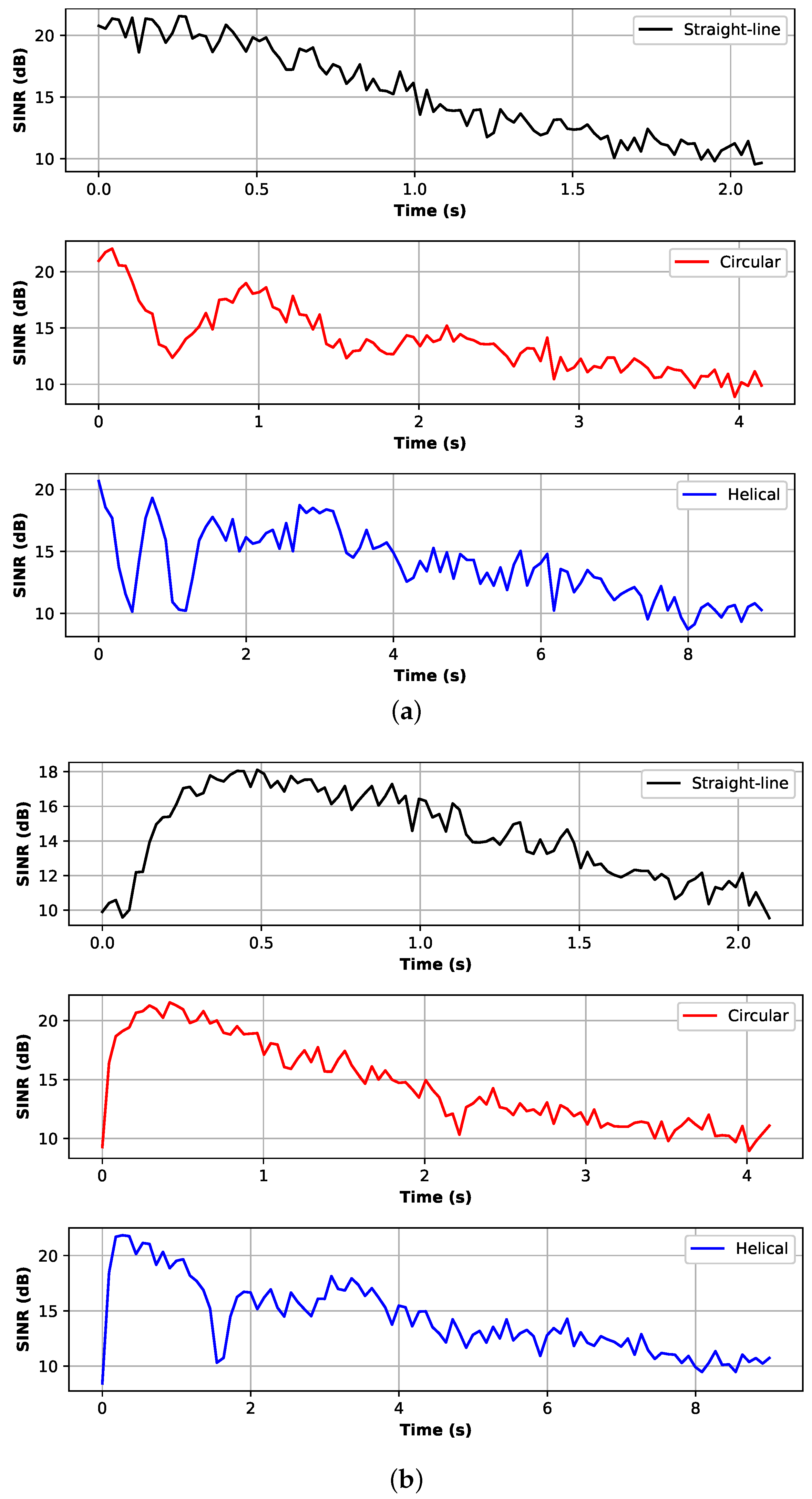
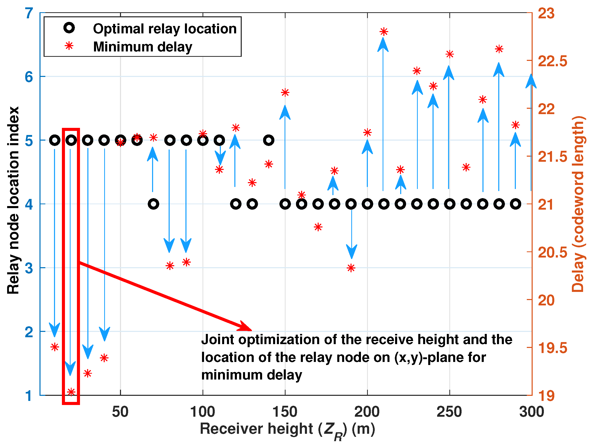
  • A straight-line, circular, and helical trajectories are considered for UAV tracing. Further, considering the general air-to-ground network with inter-relay communication, the results are presented to comprehensively characterize the optimal performance of the system towards end-to-end delay minimization. It is shown that despite the simplicity of the point-to-point direct link, the latency of the amplify-and-forward (AF) relayed-based link can be lower if the relay is properly located.
  • In addition, the power consumption restriction in the air-to-ground and air-to-air networks is considered. Within the range of allowable system latency, the optimal transmit power is derived based on the location information of a UAV. From the analysis, it is shown that increasing the transmission power is not always the proper solution to the delay minimization problem.
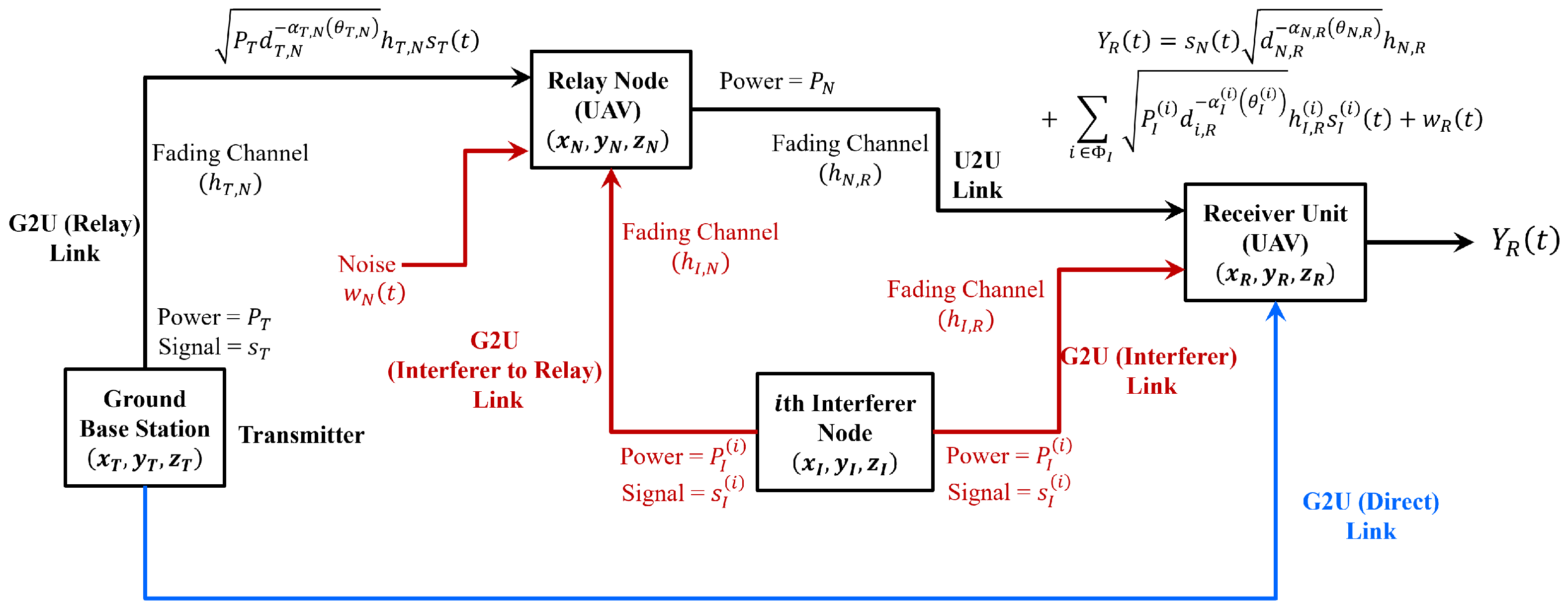
The rest of the paper is organized as follows. In Section 2, the system model is presented. The delay analysis is presented in Section 3 whereas results and discussions are depicted in Section 4. The conclusions are drawn in Section 5 whereas Section 6 describes the potential challenges and future work. The list of abbreviations and their definitions used in this paper are listed in Abbreviations.

2. System Model

An interference network is considered, where a transmitted signal is corrupted by the interference signal plus the additive white Gaussian noise (AWGN). In this noise-plus interference-limited network, there can be two types of communication links: a direct link from the ground base station (BS) to the receiver UAV and a relay-assisted link from the BS to the receiver UAV. Let the ground BS, located at  ( x T , y T , 0 ) , communicates to the receiver  ( R x )  located at  ( x R , y R , z R )  in the presence of interfering nodes located at  ( x I ( i ) , y I ( i ) , 0 ) , i Φ I Φ I  is a subset containing all interfering nodes transmitting at time t.
Let the BS transmits with power  P T  over a channel with path loss exponent  α T  and fading coefficient  h T d T = x T x R 2 + y T y R 2 + z T z R 2  is the distance between the BS and  R x s T  is a code word of length N and is a sequence of N numbers such that  s T = ( s T 1 , s T 2 , · · · , s T N ) .  The code word  s T  for an underlying ground-to-UAV channel may be thought of geometrically as a point in  N -dimensional Euclidean space. The impact of the channel impairment due to the Gaussian noise and interference is then to move  s T  to a nearby point according to a spherical Gaussian distribution.  s T ( t )  are random symbols drawn from a constellation size M with unitary mean power.  P I ( i )  denotes the transmit power of the ith interfering node. The notations used in this manuscript are listed in Table 1.
An AF relay channel with one hop is considered, as illustrated in Figure 1.
To avoid interference between the ground BS and the relay, it is assumed that the information transmission is conducted via time division where the transmission from the ground BS to the receiver is divided into two time slots. In the first slot, the signal is received by the relaying UAV, which is then amplified, and in the second slot, the amplified signal is received by the receiver UAV. An arbitrary relay UAV can normalize and re-transmit the received signal. With the power  P N , the re-transmitted signal  s N  is represented by:
s N ( t ) = P N Y N t E Y N t 2 = P N P T d T , N α T , N θ T , N h T , N s T t + w N t P T d T , N α T , N θ T , N h T , N 2 + B T N N 0 ,
where  P T  is the transmit power of the ground BS and  w N  denotes the white noise at the input of the relaying UAV.  E [ · ]  represents the expectation operation. Following (2), the signal received at the receiver is expressed as:
Y R t = s N ( t ) d N , R α N , R θ N , R h N , R + i Φ I P I i d i , R α I i θ I i h I , R i s I i t + w R t .
Figure 2 illustrates the signal flowchart of the underlying system.
We consider that the G2A and the A2A communication links experience LOS propagation with LOS probability  P L O S , h h { h T , h T , N , h N , R , h I , R , h I , N } , expressed as [20]:
P L O S , h = 1 1 + f 1 exp f 2 θ h f 1 ,
where  f 1  and  f 2  are environment-dependent parameters determined by the building density and heights. Due to the LOS path for all the described links, the small-scale channel fading gain h can be assumed to follow the Rician model with PDF given by:
f h h = h σ h 2 exp h 2 + ρ h 2 2 σ h 2 I 0 h ρ h σ h 2 , h 0 ,
where  σ h  and  ρ h  represent the strength of the LOS and Non-Line-of-Sight (NLOS) components.  I 0 ( · )  is the zeroth order modified Bessel function of the first kind. Following (4), the Rice factor  K h (dB) of any link  h { h T , R , h T , N , h N , R , h I , R , h I , N } , can then be defined as  K h (dB)  = 10 log 10 ( ρ h 2 2 σ h 2 ) . We like to point out that the Rice factor  K h  is a function of the parameters such as the carrier frequency and the elevation angle  θ h  [13].
We define the instantaneous signal-to-noise ratio (SNR) of arbitrary link  u v , from the transmitter  u , u { T , N }  to the receiver  v , v { N , R } , over the known interference channel as:
λ u v = P u d u , v α u v θ u v h u , v 2 B u v N 0 ,
and the power ratio between the intended received signal at  v , v { N , R }  from  u , u { T , N } , and the interference signal from the ith interfering node is expressed as:
γ u v ( i ) = P u d u , v α u , v θ u , v h u , v 2 i Φ I P I i d i , v α I , v i θ I , v i h I , v i 2 .
The expression in (6) is general enough to be treated as a signal-to-interference ratio (SIR).
Following the results obtained in Equations (5) and (6), the expression for the signal-to-interference plus noise ratio (SINR) can readily be obtained as:
Ξ u v ( i ) = P u d u , v α u , v θ u , v h u , v 2 i Φ I P I i d i , v α I , v i θ I , v i h I , v i 2 + B u v N 0 .
Averaging over the fading statistics described in (4), we obtain the average received SNR  λ ¯ u v  as illustrated in (8).  G m , n s , t [ · ]  in (8) represents the Meijer G-function [21]. The derivation steps are provided in the next subsection.
λ ¯ u v = P u d u , v α u , v θ u , v 2 π σ h u , v 2 B u v N 0 exp ρ h u , v 2 2 σ h u , v 2 G 3 , 4 2 , 1 2 ρ h u , v 2 σ h u , v 2 2 , 1 , 1 2 0 , 2 , 0 , 1 2 .

Proof of (8)

Utilizing (4) and (5) and applying the identities [22] (eq. 03.02.26.0006.01) and [22] (eq. 01.03.26.0007.01), the average received SNR for the link  u v  can be expressed as depicted in (9).
λ ¯ u , v = P x d u , v α u , v θ u , v B u v N 0 π σ h u , v 2 exp ρ h u , v 2 2 σ h u , v 2 0 h u , v 3 G 1 , 3 1 , 0 h u , v 2 ρ h u , v 2 σ h u , v 2 1 2 0 , 0 , 1 2 Term I h u , v 3 G 1 , 2 1 , 1 h u , v 2 2 σ h u , v 2 1 1 , 0 G 1 , 3 1 , 0 h x y 2 ρ h u , v 2 σ h u , v 2 1 2 0 , 0 , 1 2 Term II d h u , v .
Applying the identity [22] (eq. 07.34.21.0009.01), and by utilizing the fact that the gamma function has simple poles at negative integers, it can be readily shown that the integral in the Term I in (9) is guaranteed to approach zero irrespective of the values of  σ h u , v 2  and  ρ h u , v 2 . We like to point out that the gamma function is a meromorphic function that has simple poles at negative integers [23]. Finally, applying the identity [22] (eq. 07.34.21.0011.01), the integral depicted in Term II can be computed to a closed form as  2 σ h u , v 4 G 3 , 4 2 , 1 2 ρ h u , v 2 σ h u , v 2 2 , 1 , 1 2 0 , 2 , 0 , 1 2 . Substituting the equivalent closed-form expressions corresponding to Term I and Term II in (9), the expression for the average received SNR is obtained as shown in (8).

3. Delay Analysis

The critical and important questions we would like to answer in this work are:
  • What is the transmission latency of the G2U communication link under the given system parameters?
  • What are the optimal locations of the relay and the UAV to have a positive impact in minimizing the transmission delay?
More precisely, our objective is to minimize the delay in transmitting messages between the transmitter and the receiver in UAV communication while guaranteeing a required level of reliability  ϕ e , such that,
P e d c , R c ϕ e ,
where  P e d c , R c  represents the average error probability of the code with length  d c  and rate  R c . The channel code rate R is a function of the input target signal distribution  f T , the input interference signal distribution  f I λ , and  γ . The channel code rate  R c  is achievable if there is an encoding function to map each transmitted message S to  s T  and there is another decoding function to map each received signal Y and interference information to a transmitted message as  S ^ , such that the average error probability  P e ( d c , R c ) P r [ S S ^ ] 0  when N goes large. Following this, we define the reliability function in terms of the error exponent of the channel as [24]:
E R c = lim d c sup ln P e , min d c , R c d c ,
where  sup ( · )  represents the supermum function and  P e , min d c , R c  denotes the infimum or the greatest lower bound of the error probability over all  d c , R c  codes for a given  d c  and  R c . It can be readily shown that the error exponent depicted in (11) is upper bounded by the sphere packing exponent:
E R c max ρ > 0 E 0 ρ ρ R c ,
where:
E 0 ρ = log P Y R s T 1 1 + ρ d P s T 1 + ρ d Y R
where  P s T  denotes the cumulative distribution function of the input  s T  and  P Y R s T  is the probability density (or mass) function of the output Y given the input  s T ρ  is a parameter,  0 ρ 1 , and should be selected such that  d c  is minimized. Utilizing (8), (10) and (12), and applying the identity [25] (Equation (11)), the minimum transmission delay introduced into the channel in order to satisfy the reliability constraint is given by:
d c ρ B log ϕ e G 2 , 2 1 , 2 λ ¯ u v 1 , 1 1 , 0 ,
where B represents the information bits in the codeword of length  d c .
We define the capacity of the uplink ground-to-UAV channel impaired by the known interference as:
C λ , γ = sup f T inf f I R c f T , f I , λ , γ subject to E s I 2 = 1 , E s T 2 = 1
Next, we present a tight upper bound for  C λ , γ  defined in (15).
To decode the transmitted message S correctly with a low probability of error, the conditional entropy  H ( S | Y R , s I )  has to be close to zero [26]. Following this, and applying Fano’s inequality [27] into the definition of channel entropy, it can be readily shown that:
d c R c f T , f I , λ , γ I S ; Y R , s I + d c ζ d c ,
where  ζ N  is the error detection parameter satisfying the condition  lim d c ζ d c = 0 . Applying the definition of mutual information and utilizing the fact that S and  s I  are independent, (16) can be written as:
d c R c f T , f I , λ , γ H Y R s I H Y R S , s I + ζ d c ,
where  H Y R s I  can be interpreted as the uncertainty in Y conditional on  s I H Y R S , s I  accounts for the reduction in uncertainty of Y conditional on  s I  from the observation of  s I . Substituting the expressions for  H Y R s I  and  H Y S , s I  into (17), the tight upper bound for the capacity of the air-to-ground channel is derived as illustrated in (18).  N p  in the summation term in (18) denotes the packet length.  T c  represents the block of symbols over which the channel is assumed to be constant. Next, we provide the detailed derivation steps of (18).
R c , u v T c 1 T c log 1 + P u d u , v α u , v θ u , v h u , v 2 B u v N 0 + 1 N p j = 1 N p / T c E s I , j log 1 + P u d u , v α u , v θ u , v h u , v 2 i Φ I P I i d i α I , v i θ I , v i h I , v i 2 s I , j i 2 + B u v N 0 + ζ d c .

3.1. A Note on Fano’s Inequality

Fano’s inequality states that the probability of error  P e , which is the probability of incorrectly choosing one hypothesis over the other, is bounded by:
P e ( H ( A | B ) 1 ) log 2 ( K )
Fano’s inequality states that the probability of error is lower bounded by the conditional entropy of the hypothesis given the observed data, divided by the logarithm of the number of hypotheses. It implies that as the conditional entropy decreases (indicating more informative data), the probability of error decreases.

3.2. Proof of (18)

Applying the chain rule and utilizing the fact that conditioning reduces entropy,  H Y R s I  can readily be expressed as shown in (20).
H Y R s I j = 1 N p / T c max trace E s T , j , s T , j * T E s I , j log π e T × det P T d T , R α T , R θ T , R h T , R E s T , j , s T , j * + i Φ I P I i d i , R α I , R i θ I , R i s I , j i s I , j i * + B T R N 0 I .
where I is the identity matrix. Subscript j represents the block index. It follows that  N p / T c  should be a positive integer. Following a similar approach as illustrated in [28], with some simple mathematical manipulations, (20) can be written as illustrated in (21).
Utilizing the chain rule for entropy,  H Y S , s I  can readily be expressed as shown in (22). Applying the Markov chain, the expression in (22) is reduced to the expression as illustrated in (23).
H Y R s I N p log π e + N p T c 1 T c log P T d T , R α T , R θ T , R + B T R N 0 + j = 1 N p / T c E s I , j log P T d T , R α T , R θ T , R + i Φ I P I i d i , R α I , R i θ I , R i s I , j i 2 + B T R N 0 .
H Y R S , s I = j = 1 N p / T c H y j y 1 , · · · , y j 1 , S , s I = j = 1 N p / T c H i Φ I P I i d I , R α I , R i θ I , R i h I , j i s I , j i + w R y 1 , · · · , y j 1 , S , s T , s I .
H Y S , s I = N p log π e + N p T c 1 T c log B T R N 0 + j = 1 N p / T c E s I , j log i Φ I P I i d I , R α I , R i θ I , R i s I , j i 2 + w R .
Substituting (21) and (23) into (12), and applying simple mathematical manipulations, yields (18).
P u , min 1 + ρ exp ρ B log ϕ e d c , max i Φ I P I i d I , v α I , v i θ I , v i h I , v i 2 + B u v N 0 1 × 1 d u , v α u , v θ u , v h u , v 2 .
We like to point out that, since the channel is random over a single transmission interval with the assumption that the channel state information is not available to the BS, and considering the capacity as defined in (15), it is now possible that  C λ , γ = 0  with nonzero probability irrespective of the link range and transmission power. Therefore, the power allocation approach may not be an optimal solution for the uplink G2U networks. Moreover, it is now impossible to guarantee successful information transmission with  ϕ e = 0  and  C λ , γ > 0 .
Next, we obtain the minimum transmit power  P u , min  required at node u, given the maximum allowable delay  d c , max  and the reliability constraint  ϕ e  at the receiver v. Following (2), (12) and (13), the tight upper bound on the transmit power requirement, subject to the reliability constraint and the maximum delay threshold, can readily be derived as shown in (24).

4. Results and Analysis

The simulation parameters are summarized in Table 2. We consider a slow-fading channel, where the actual channel gains are assumed to be constant, however, random over a single transmission interval. Unless otherwise stated, the interferer coordinates are set to (0, 500 m, 0). To get a satisfactory statistical average, for each link configuration parameter set, 1000 realizations of normally distributed independent random variables are generated. The delay is then obtained by averaging the results over 1000 realizations. For brevity, we assume one interfering node. We consider the following three cases to describe the link geometries.
  • Case I: It considers a scenario where the receiver is located above in a region near the vicinity of the transmitter;
  • Case II: It considers a scenario where the receiver is located above in a region near the midway of the line joining the transmitter and the receiver;
  • Case III: It considers a scenario where the receiver is located above in a region near the vicinity of the interfering node.

Performance over Different UAV Trajectories and Optimal Relay Selection

For a detailed analysis, we consider the following UAV trajectories. That is a straight-line trajectory, circular trajectory, and helical trajectory. Figure 3 shows the signal-to-interference plus noise ratio (SINR) relative to the time-of-fly for different trajectories. The transmitter location is set to  ( 0 , 0 , 0 ) . In obtaining the results shown in Figure 3a, the interferer location is set to  ( 30 m , 10 m , 0 ) , whereas for Figure 3b, the interferer location is set to  ( 35 m , 15 m , 0 ) . Three trajectory options are examined: straight-line, circular, and helical paths. The results reveal significant variations in SINR values along the trajectories. The straight-line path exhibits decaying SINR values along the trajectory, as it is the shortest and the direct path. The helical path shows periodic fluctuations in SINR due to changing distances from the transmitter and interference source. Analyzing the SINR and flight times for different UAV trajectories provides valuable insights into their impact on wireless communication systems. The results emphasize the importance of trajectory selection in achieving reliable and efficient communication links. Moreover, it is important to note that, as the interferer changes its location, the pattern changes. These results can also be verified from Figure 4. Figure 4a,b represent the SINR profile for different interferer locations. It can be inferred that the statistical characteristics of SINR are closely related to many performance metrics of UAV networks. By understanding the variations in SINR and flight time, system designers and operators can make informed decisions to optimize UAV communication performance.
To maximize the SINR and thereby minimize the latency, we consider the problem of selecting the optimal relayed UAV node. Figure 5 shows the optimal relayed UAV selection for three different trajectories. The transmitter is set to  ( 0 , 0 , 0 ) , whereas an interferer is located at  ( 10 m , 20 m , 0 ) . The objective function is to maximize the received SINR, and the constraint includes the total transmit power.
Figure 6 shows the SIR variation with receiver height  ( z R )  at different positions along the line joining the BS and the interferer. For Case I, as  z R  increases, the signal of interest becomes weaker, and hence, the interference becomes relatively stronger. On the contrary, for Case III, increasing  z R  results in a weaker interference thereby making the signal of interest relatively stronger and hence higher SIR. However, the nearly constant SIR for case II can be attributed to the fact that both, the signal of interest and the interference signal, become weak proportionally with increasing  z R .
In Figure 7a–c, we show the results for the delay, while varying the receiver height  z R  for several channel conditions, i.e., over the interference-limited channel, and when  λ ¯ = 30  dB and  λ ¯ = 0  dB, respectively. In Figure 7a, as expected, we can observe that for an interference-limited channel, when the receiver is located above the transmitter, the delay is an increasing function of the receiver height. In contrast, when the receiver moves in either direction in a line joining the transmitter and the interferer, the delay shows non-monotonic behaviors with the receiver height. Indeed, for the given link configuration and the placements of the ground BS and the interferer, the delay first decreases with increasing the height till the optimal height is obtained and then increases with the height. This quasi-monotonic behavior can be attributed to the fact that increasing the receiver height beyond the optimal height causes higher interference and path loss. In contrast to the interference-limited channel, slightly different trends are observed in the interference-plus-noisy channel. For example, in Figure 7b, when  λ ¯ = 30  dB, the delay increases with  z R  irrespective of  x R  and  y R , however, in Figure 7c, when  λ ¯  is very low, the three curves, however, cannot be distinguished. It shows that noise is a dominating factor in this case.
Figure 8 presents the end-to-end delay profile relative to the receiver height for the direct link over different channel conditions for Case II. The different curves in Figure 8a,b demonstrate the impact of varying the receiver along the mid-point on the line joining the transmitter and the interferer. Based on the results, a few important observations can be made.
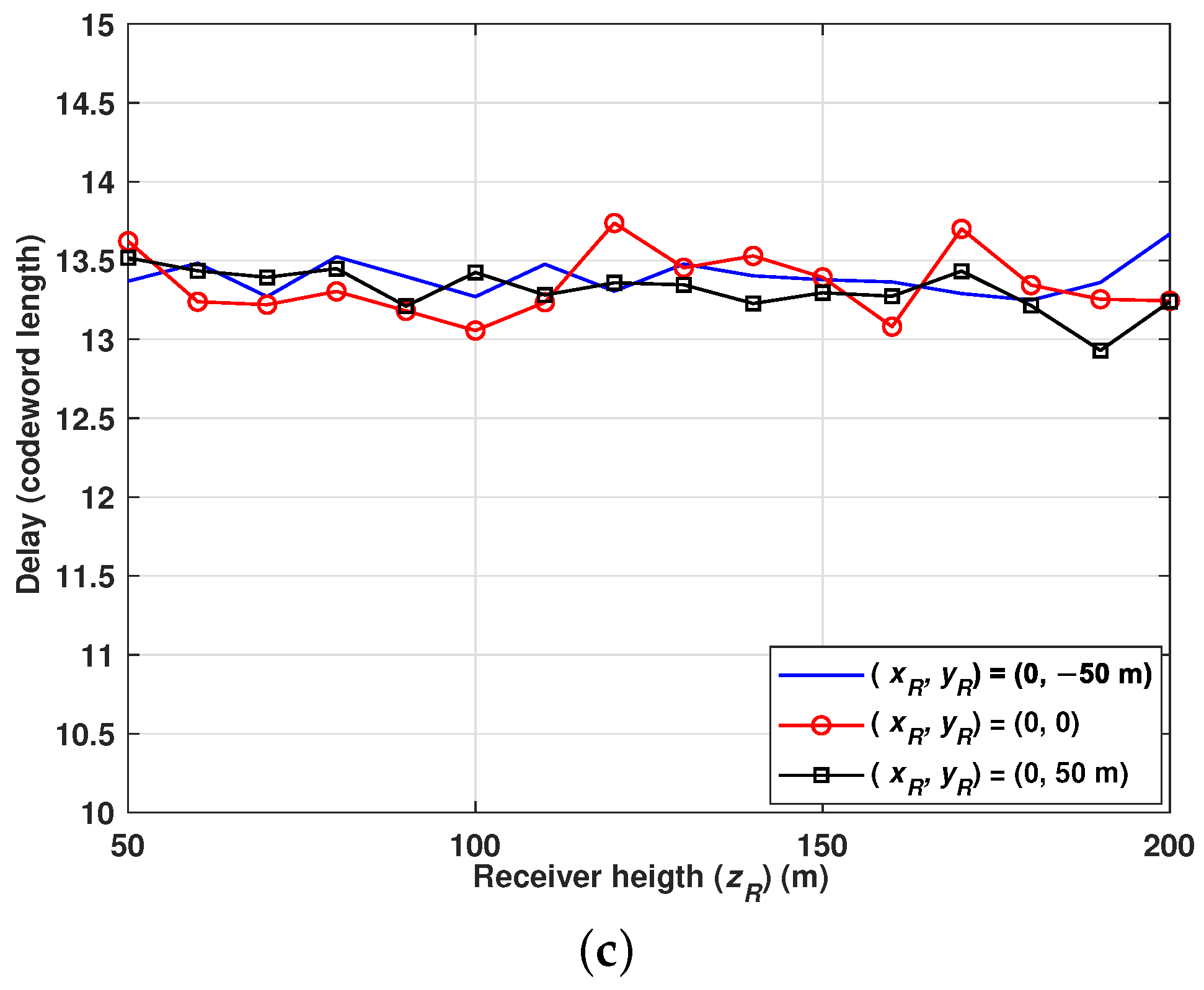
  • If the UAV is located near the midpoint such that,  d T , N > d i , R , the delay first increases rapidly with the height and then decreases gradually with further increasing the UAV height. This monotonic behavior can be attributed to the fact that increasing the height initially causes received signal power to decrease relatively at a higher rate than interference and thereby reduces the number of packets successfully received. However, at larger heights, the impact of the interference signal also reduces, thus causing the delay to decrease gradually.
  • Interestingly, and contrary to the above point, if the UAV is located near the midpoint such that  d T , N d i , R , increasing the height does not reflect significant changes in the delay.
Figure 9 depicts the delay performance relative to the receiver heights over different channel types for Case III. The results reveal important observations on the delay characteristics, that when the receiver is located in a region near the vicinity of the interfering node, the performance is primarily dominated by interference. Interestingly, as can be seen, the delay decreases with the increasing receiver height for all the curves under all channel conditions. Where the delay values are finite but very high. The higher delay is due to the increasing interference that reduces the success probability of transmission. Moreover, it is to be noted that, irrespective of the channel conditions, the performance is primarily dominated by interference and not by the Gaussian noise.
Given the location of the receiver and the interferer, the minimum delay a G2U communication system must encounter for different values of  λ ¯  is illustrated in Figure 10. In obtaining these curves, the interference power is kept constant at 30 dBm whereas, the reliability constraint is set to  10 4 . Following important observations can be made.
  • As can be seen, the impact of increasing the signal power in minimizing the transmission delay dominates only if the UAV is located near a region above the transmitter. However, it is to be noted that the negative rate of change of delay with respect to the change in  λ ¯  approaches zero for larger values of  λ ¯ . Moreover, it is also important to note that, as the UAV approaches a region away from the transmitter and near the interferer, the rate  d d c , min d λ ¯ 0  even for smaller values of  λ ¯ . It shows that increasing  λ ¯  gives a negligible gain in terms of minimizing the transmission delay, though may greatly enhance the outage performance.
  • As low  λ ¯  values, increasing the height of the UAV does not necessarily impact the delay performance. However, as  λ ¯  increases, the delay performance degrades with increasing the height.
Given the range of allowable system latency that guarantees that the reliability constraint is met, the minimum transmission power required at the BS for different noise-to-interference power (NIP) levels is illustrated in Figure 11. In obtaining these results, we fix the location of the receiver and the interferer at  ( 0 , 250 , 250 )  and  ( 0 , 500 , 0 ) , respectively. The reliability constraint is set to  P e ϕ e = 10 4 . The key observations from the results obtained are as follows:
  • Given the reliability constraint and fixed NIP value, there exists a non-linear relation between the allowable transmission delay and the corresponding transmit power requirements. As can be seen, the required transmit power reduces significantly when the allowable transmission delay is relaxed from its initial value. However, on further relaxing the delay requirement, the required transmit power reduces gradually. This phenomenon validates our claim that increasing the signal power beyond a certain limit may not be an optimal solution to the delay minimization problem.
  • Given the delay requirement and the reliability constraint, the required signal power increases with increasing NIP. Importantly, it is to be noted that, this behavior follows a constant rate of change of required transmit power with respect to the change in NIP, irrespective of the delay requirement.
Figure 12 shows the delay profile against the receiver height for different relay node locations. The  x R  and  y R  coordinates of the receiver are fixed to  ( 0 , 250 )  and are located midway of the line joining the transmitter and the interferer. The amplification gain of the relay UAV is set to  3  dB. However, it is assumed that there is no noise at the input of the relay. For the relay-assisted network, it can be seen that the delay increases with the height initially and then decreases. This phenomenon is more dominating when the relay node is located on the opposite side of the line joining the transmitter and the receiver. Moreover, it can be seen that, as the relay node moves closer to the region between the transmitter and the receiver, the delay performance improves. However, it is to be noted that, as the relay node moves closer to the receiver, the delay though may be lower, but increases with increasing the receiver height. Moreover, for the direct link, as the receiver height increases, there is no impact on the delay performance. Intuitively, this behavior can be attributed to the fact that, if the UAV is located near the region in the middle of the BS and the interferer, changing the UAV height vary the signals strengths from the transmitter and the interferer identically. In obtaining the results in Figure 12a–c, a few points are important to note.
  • For the relayed-assisted network, we assume that there is no direct path between the BS and the receiver UAV. Thus, the relay UAV in our case serves primarily as compensation for channel degradation due to the path loss and fading between the ground BS and the receiver UAV. Therefore, no additional diversity is achieved in this case.
  • The relayed UAV utilizes an amplify-and-forward relaying protocol. Therefore, these results will serve as a lower bound when compared with the conventional decode-and-forward protocol.
The results presented in Figure 13 are obtained with identical conditions as set in obtaining the results in Figure 12, however, the relay node is assumed to have Gaussian noise at its input with noise amplification considered.
In Figure 14, the joint optimization of the relay node and location and the receiver height is presented with the aim to minimize the delay. In obtaining the results in Figure 14, the end-to-end received average signal-to-noise power ratio is set to  2  dB whereas the amplification gain of the relay node is set to  3  dB. The relay node location index  { 1 , 2 , 3 , 4 , 5 }  corresponds to the location coordinates as  ( 0 , 50 , 50 ) ( 0 , 00 , 50 ) ( 0 , 50 , 50 ) ( 0 , 100 , 50 ) ( 0 , 150 , 50 ) , respectively.  x R  and  y R  are set to 0 and 250.
Figure 15 shows the impact of the relay node location in minimizing the delay. Interestingly, it is to be noted that due to the hammock shape of the delay profile, as illustrated in Figure 15, there is only one global minimum, and the optimal relay node location corresponding to this global minima can readily be obtained using convex optimization. Recall that in obtaining the results in Figure 15, our dual-hop AF scheme does not exploit the existence of the direct link from the BS to the UAV for the coherent combining of signals at the receiver. Ignoring the direct link in this analysis provides an upper bound on the delay that can be achieved over an interference plus noise G2U channel.
Next, as a proof of concept, we compare the proposed framework with the conventional ground-to-UAV communication system [30]. Figure 16 illustrate the improvement in the received SINR in the proposed system for different relayed locations, when compared to the conventional direct G2U communication link. In obtaining the results presented in Figure 16, for brevity, the transmitter locations for both systems are set to  ( 0 , 0 , 0 ) , whereas the horizontal coordinates of the receiver for both systems are set to  ( 0 , 300 m ) . For generating the curve for the conventional system, the parameters considered are adopted from [30]. For the proposed system, we consider three different relayed UAV locations given by  ( 0 , 50 , 50 ) , ( 0 , 100 , 50 ) ,  and  ( 0 , 150 , 50 )  (meters). The interferer location is set to  ( 0 , 0 , 500 )  (meters). It is interesting to note that, the proposed system outperforms the conventional system over the entire receiver’s height variations. For instance, when the relayed-UAV is located at  ( 0 , 50 , 150   m ) , the proposed system outperforms the conventional system by approximately 12 dB, 6 dB, and 2 dB for receiver locations  ( 0 , 300 , 10 ) , ( 0 , 300 , 50 ) ,  and  ( 0 , 300 , 300 )  (meters), respectively.

5. Conclusions

In this work, we have presented an information-theoretic framework to assess the delay of the G2U integrated network, and propose strategies for reducing the system delay. Based on the location information of the UAV in the scenarios of point-to-point G2U, we derived the tight upper bound for the channel capacity utilizing Fano’s inequality and obtained the tight lower bound on the transmit power requirement subject to the reliability constraint and the maximum delay threshold. In addition, a relay UAV in the dual-hop relay mode, with amplify-and-forward protocol, is considered, for which we jointly obtain the optimal positions of the relay and the receiver UAVs in the presence of interference, and is compared with the point-to-point G2U link which ignores the relay. Despite the simplicity of the point-to-point direct link, the latency of the AF relayed-based link can be lower if the relay is properly placed. We further extended this observation and its impacts on communication performance by applying the optimal relay selection in various trajectories for UAV tracing, including three typical trajectories listed in this paper: straight-line, circular, and helical. We identified the optimal relay selection along each of the traces. The optimal relay selection provides benefits in terms of SNR, which could be translated into dramatic increases in power gain, energy efficiency, range, and capacity. Moreover, our results show that increasing the transmit power may not always be an optimal solution for latency minimization problems, especially when the receiver UAV is not located near a region above the transmitter, though it may significantly improve the outage performance. This work contributes to fundamental research in enabling the UAVs formed networks serving as aerial access points or relays to enhance the coverage and quality of service in SAGIN coexistence networks. We have formulated the problem to optimize the relay node location with the objective of minimizing the delay. We have found that when the receiver’s horizontal coordinates are fixed to  ( 0 , 250   m )  and are located in a region midway of the line joining the transmitter and the interferer, the delay increases with the height initially and then decreases. For instance, when the amplification gain of the relay node is set to  3  dB with location coordinates set to (0, 0, 50 m), the delay (codeword length) increases from 23 to 42 when the receiver’s height increases from 10 m to 50 m. However, on further increasing the receiver’s height from 50 m to 300 m, the delay decreases sharply from 42 to 30. A potential extension of this work relates to investigating the ground-to-multi-relayed UAV networks, which can offer higher reliability at the cost of even more system complexity.

6. Challenges and Future Work

Despite the great potential of the proposed framework in identifying the optimal relay node position and receiver location in the presence of an interferer while minimizing the latency, the UAV-enabled communication faces a few challenges that need to be efficiently integrated into the analysis. These challenges include the distortion in the received signal power due to the hovering of the relay UAV and the receiver UAV. In particular, UAVs introduce mobility-related challenges. Varying orientations due to the hovering may affect the link quality and may result in a jitter noise.
Future work could be to include the channel impairment due to the hovering conditions and performing the outdoor experimental analysis. We would also like to conduct an experiment considering multiple UAV relay nodes and multiple receiver UAVs.

Author Contributions

Conceptualization: S.A., J.Y. and Y.W.; methodology: S.A., J.Y. and Y.W.; validation: S.A., J.Y. and Y.W.; writing—original draft preparation: S.A. and J.Y.; writing—review and editing: S.A., J.Y. and Y.W.; supervision: Y.W.; project administration: Y.W.; funding acquisition: Y.W. All authors have read and agreed to the published version of the manuscript.

Funding

This research received no external funding.

Data Availability Statement

No new data were created or analyzed in this study. Data sharing is not applicable to this article.

Acknowledgments

The authors would like to thank the Reviewers for their insightful comments.

Conflicts of Interest

The authors declare no conflict of interest.

Abbreviations

The following abbreviations are used in this manuscript:
3GPPThird Generation Partnership Project
AFAmplify-and-Forward
AWGNAdditive White Gaussian Noise
BSBase Station
C2Command and Control
eMBBEnhanced Mobile Broadband
eVTOLElectrical Vertical Take-off and Landing
FAAFederal Aviation Administration
FCCFederal Communications Commission
G2UGround-to-UAV
LOSLine-of-Sight
mMTCMassive Machine-Type Communication
NLOSNon-Line-of-Sight
OTAOver the Air
QoSQuality-of-Service
SAGINSpace-Air-Ground Integrated Networks
SCSCSatellite-Terrestrial Co-exist at Scale Communication Infrastructure
SINRSingal-to-Interference Plus Noise Ratio
SIRSingal-to-Interference Ratio
SNRSingal-to-Noise Ratio
U2UUAV-to-UAV
UAVUnmanned Aerial Vehicle
URLLCUltra-Reliable and Low-Latency Communication Link

References

  1. Ma, Z.; Xiao, M.; Xiao, Y.; Pang, Z.; Poor, H.V.; Vucetic, B. High-reliability and low-latency wireless communication for internet of things: Challenges, fundamentals, and enabling technologies. IEEE Internet Things J. 2019, 6, 7946–7970. [Google Scholar] [CrossRef]
  2. Popovski, P.; Stefanović, Č.; Nielsen, J.J.; De Carvalho, E.; Angjelichinoski, M.; Trillingsgaard, K.F.; Bana, A.S. Wireless access in ultra-reliable low-latency communication (URLLC). IEEE Trans. Commun. 2019, 67, 5783–5801. [Google Scholar] [CrossRef] [Green Version]
  3. Shirvanimoghaddam, M.; Mohammadi, M.S.; Abbas, R.; Minja, A.; Yue, C.; Matuz, B.; Han, G.; Lin, Z.; Liu, W.; Li, Y.; et al. Short block-length codes for ultra-reliable low latency communications. IEEE Commun. Mag. 2018, 57, 130–137. [Google Scholar] [CrossRef] [Green Version]
  4. Muruganathan, S.D.; Lin, X.; Määttänen, H.L.; Sedin, J.; Zou, Z.; Hapsari, W.A.; Yasukawa, S. An overview of 3GPP release-15 study on enhanced LTE support for connected drones. IEEE Commun. Stand. Mag. 2021, 5, 140–146. [Google Scholar] [CrossRef]
  5. Zeng, Y.; Lyu, J.; Zhang, R. Cellular-connected UAV: Potential, challenges, and promising technologies. IEEE Wirel. Commun. 2018, 26, 120–127. [Google Scholar] [CrossRef]
  6. Lin, X.; Yajnanarayana, V.; Muruganathan, S.D.; Gao, S.; Asplund, H.; Maattanen, H.L.; Bergstrom, M.; Euler, S.; Wang, Y.P.E. The sky is not the limit: LTE for unmanned aerial vehicles. IEEE Commun. Mag. 2018, 56, 204–210. [Google Scholar] [CrossRef] [Green Version]
  7. Mak, B.; Sudhanshu, A.; Ying, W.; Jonathan, A. Characterization of Low-Latency Next-Generation eVTOL Communications: From Channel Modeling to Performance Evaluation. Electronics 2023, 12, 2838. [Google Scholar] [CrossRef]
  8. Tran, D.H.; Nguyen, V.D.; Chatzinotas, S.; Vu, T.X.; Ottersten, B. UAV relay-assisted emergency communications in IoT networks: Resource allocation and trajectory optimization. IEEE Trans. Wirel. Commun. 2021, 21, 1621–1637. [Google Scholar] [CrossRef]
  9. Hosseinalipour, S.; Rahmati, A.; Dai, H. Interference avoidance position planning in dual-hop and multi-hop UAV relay networks. IEEE Trans. Wirel. Commun. 2020, 19, 7033–7048. [Google Scholar] [CrossRef]
  10. Wang, Y.; Gorski, A.; DaSilva, L.A. AI-Powered Real-Time Channel Awareness and 5G NR Radio Access Network Scheduling Optimization. In Proceedings of the 2021 17th International Conference on the Design of Reliable Communication Networks (DRCN), Milano, Italy, 19–22 April 2021. [Google Scholar] [CrossRef]
  11. Wang, Y.; Jere, S.; Banerjee, S.; Liu, L.; Modeling, V.; Dayekh, S. Anonymous Jamming Detection in 5G with Bayesian Network Model Based Inference Analysis Sachin Shetty. In Proceedings of the IEEE International Conference on High Performance Switching and Routing, Virtual, 6–8 June 2022. [Google Scholar]
  12. Jere, S.; Wang, Y.; Aryendu, I.; Dayekh, S.; Liu, L. Machine Learning-assisted Bayesian Inference for Jamming Detection in 5G NR. arXiv 2023, arXiv:2304.13660. [Google Scholar]
  13. Salehi, F.; Ozger, M.; Neda, N.; Cavdar, C. Ultra-Reliable Low-Latency Communication for Aerial Vehicles via Multi-Connectivity. In Proceedings of the 2022 Joint European Conference on Networks and Communications & 6G Summit (EuCNC/6G Summit), IEEE, Grenoble, France, 7–10 June 2022; pp. 166–171. [Google Scholar]
  14. Ladosz, P.; Oh, H.; Chen, W.H. Optimal positioning of communication relay unmanned aerial vehicles in urban environments. In Proceedings of the 2016 International Conference on Unmanned Aircraft Systems (ICUAS), IEEE, Arlington, VA, USA, 7–10 June 2016; pp. 1140–1147. [Google Scholar]
  15. Faqir, O.J.; Nie, Y.; Kerrigan, E.C.; Gündüz, D. Energy-efficient communication in mobile aerial relay-assisted networks using predictive control. IFAC-PapersOnLine 2018, 51, 197–202. [Google Scholar] [CrossRef]
  16. Zeng, Y.; Zhang, R.; Lim, T.J. Throughput maximization for UAV-enabled mobile relaying systems. IEEE Trans. Commun. 2016, 64, 4983–4996. [Google Scholar] [CrossRef]
  17. Ono, F.; Ochiai, H.; Miura, R. A wireless relay network based on unmanned aircraft system with rate optimization. IEEE Trans. Wirel. Commun. 2016, 15, 7699–7708. [Google Scholar] [CrossRef]
  18. Rahmati, A.; Yapici, Y.; Rupasinghe, N.; Guvenc, I.; Dai, H.; Bhuyan, A. Energy efficiency of RSMA and NOMA in cellular-connected mmWave UAV networks. In Proceedings of the 2019 IEEE International Conference on Communications Workshops (ICC Workshops), IEEE, Shanghai, China, 20–24 May 2019; pp. 1–6. [Google Scholar]
  19. Wang, Y.; Gorski, A.; da Silva, A. Development of a Data-Driven Mobile 5G Testbed: Platform for Experimental Research. In Proceedings of the IEEE International Mediterranean Conference on Communications and Networking, Athens, Greece, 7–10 September 2021. [Google Scholar]
  20. Series, P. Propagation data and prediction methods required for the design of terrestrial broadband radio access systems operating in a frequency range from 3 to 60 GHz. In Recommendation ITU-R P.1410-5; ITU Radiocommunication Sector: Geneva, Switzerland, 2013; pp. 1410–1415. [Google Scholar]
  21. Gradshteyn, I.S.; Ryzhik, I.M. Table of Integrals, Series, and Products; Academic Press: Cambridge, MA, USA, 2014. [Google Scholar]
  22. Wolfram Research, Inc. The Wolfram Functions Site; Wolfram Research, Inc.: Champaign, IL, USA, 1999. [Google Scholar]
  23. Thukral, A.K. Factorials of real negative and imaginary numbers-A new perspective. SpringerPlus 2014, 3, 1–13. [Google Scholar] [CrossRef] [PubMed] [Green Version]
  24. Gallager, R.G. Information Theory and Reliable Communication; Springer: Berlin/Heidelberg, Germany, 1968; Volume 588. [Google Scholar]
  25. Adamchik, V.S.; Marichev, O. The algorithm for calculating integrals of hypergeometric type functions and its realization in REDUCE system. In Proceedings of the International Symposium on Symbolic and Algebraic Computation, Tokyo, Japan, 20–24 August 1990; pp. 212–224. [Google Scholar]
  26. Tse, D.; Viswanath, P. Fundamentals of Wireless Communication; Cambridge University Press: Cambridge, UK, 2005. [Google Scholar]
  27. Scarlett, J.; Cevher, V. An introductory guide to Fano’s inequality with applications in statistical estimation. arXiv 2019, arXiv:1901.00555. [Google Scholar]
  28. Zhang, S.; Liew, S.C.; Chen, J. The capacity of known interference channel. IEEE J. Sel. Areas Commun. 2015, 33, 1241–1252. [Google Scholar] [CrossRef]
  29. Chang, H.; Wang, C.X.; Liu, Y.; Huang, J.; Sun, J.; Zhang, W.; Gao, X. A novel nonstationary 6G UAV-to-ground wireless channel model with 3-D arbitrary trajectory changes. IEEE Internet Things J. 2020, 8, 9865–9877. [Google Scholar] [CrossRef]
  30. Kim, M.; Lee, J. Outage probability of UAV communications in the presence of interference. In Proceedings of the 2018 IEEE Global Communications Conference (GLOBECOM), IEEE, Abu Dhabi, United Arab Emirates, 9–13 December 2018; pp. 1–6. [Google Scholar]
  31. Goldsmith, A.J. The capacity of downlink fading channels with variable rate and power. IEEE Trans. Veh. Technol. 1997, 46, 569–580. [Google Scholar] [CrossRef]
Figure 1. System model.
Drones 07 00479 g001
Figure 2. Signal flowchart of the proposed system.
Drones 07 00479 g002
Figure 3. Signal-to-interfernce plus noise ratio (SINR) relative to the time-of-fly for different trajectories. (a) SINR relative to the time of flight:  ( X I , Y I , Z I ) = ( 30 m , 10 m , 0 ) . (b) SINR relative to the time of flight:  ( X I , Y I , Z I ) = ( 35 m , 15 m , 0 ) .
Drones 07 00479 g003
Figure 4. SINR profile along different trajectories relative to various interferer’s locations. (a) SINR profile:  ( X I , Y I , Z I ) = ( 30 m , 10 m , 0 ) . (b) SINR profile:  ( X I , Y I , Z I ) = ( 35 m , 15 m , 0 ) .
Drones 07 00479 g004
Figure 5. Optimal relay selection for different trajectories. (a) Optimal relay selection: Straight-line trajectory. (b) Optimal relay selection: Circular trajectory. (c) Optimal relay selection: Helical trajectory.
Drones 07 00479 g005aDrones 07 00479 g005b
Figure 6. Signal-to-interference ratio relative to the receiver height for different  y R  along the line joining the transmitter and the interferer.
Drones 07 00479 g006
Figure 7. Delay profile as a function of the receiver height over different channel conditions (Case I). (a) Interference-limited channel. (b) Interference channel with end-to-end received signal-to-noise power ratio  λ = 30  dB. (c) Interference channel with end-to-end received signal-to-noise power ratio  λ = 0  dB.
Drones 07 00479 g007aDrones 07 00479 g007b
Figure 8. Delay profile as a function of the receiver height over different channel conditions (Case II). (a) Interference-limited channel. (b) Interference channel with end-to-end received signal-to-noise power ratio  λ = 0  dB.
Drones 07 00479 g008
Figure 9. Delay profile as a function of the receiver height over different channel conditions (Case III). (a) Interference-limited channel. (b) Interference channel with end-to-end received signal-to-noise power ratio  λ = 30  dB.
Drones 07 00479 g009aDrones 07 00479 g009b
Figure 10. Minimum delay relative to received SNR for different receiver locations.
Drones 07 00479 g010
Figure 11. Required signal power relative to the minimum delay for different NIP levels.
Drones 07 00479 g011
Figure 12. Delay profile relative to the relay node location for different receiver heights (without noise amplification at the relay node). (a) Received signal-to-noise power ratio  λ = 2  dB. (b) Received signal-to-noise power ratio  λ = 0  dB. (c) Received signal-to-noise power ratio  λ = 5  dB.
Drones 07 00479 g012
Figure 13. Delay profile relative to the relay node location for different receiver heights (with noise amplification at relay node). (a) Received signal-to-noise power ratio  λ = 2  dB. (b) Received signal-to-noise power ratio  λ = 0  dB. (c) Received signal-to-noise power ratio  λ = 5  dB.
Drones 07 00479 g013
Figure 14. Optimal link configuration for minimum delay.
Drones 07 00479 g014
Figure 15. Delay profile relative to the relay node location.
Drones 07 00479 g015
Figure 16. Performance comparison of the proposed framework with the conventional G2U communication system.
Drones 07 00479 g016
Table 1. Notations.
Table 1. Notations.
ParameterDescription
  d c Block length of the code word  s T
  R c Code rate
  P T Transmit power
  P I ( i ) Transmit power of the ith interfering node
  P N Power of the amplifying node
  ϕ e Reliability constraint
  Φ I Number of active interfering nodes at any time t
  h u , v channel gain between the nodes u and v
  α u , v Path loss exponent of the link  u v
  α I , v ( i ) Path loss exponent of the link between the ith interferer and the vth receiver
{ θ u , v A , D , ( θ u , v E , D ) } θ u , v     Azimuthal (Elevation) angle of Departure for the link between the uth transmitting node and vth receiving node
  { θ I , v A , D ( i ) , ( θ I , v E , D ( i ) ) } θ I , v ( i ) Azimuthal (Elevation) angle of Departure between the receiver v and the ith interfering node
  { θ u , v A , A , ( θ u , v E , A ) } θ u , v Azimuthal (Elevation) angle of arrival for the link between the uth transmitting node and vth receiving node
  { θ I , v A , A ( i ) , ( θ I , v E , A ( i ) ) } θ I , v ( i ) Azimuthal (Elevation) angle of arrival between the receiver v and the ith interfering node
  d u , v 3D distance between the nodes u and v
  w R ( t ) AWGN noise at the input of the receiver
  w N ( t ) AWGN noise at the input of the relay node
  N 0 Noise spectral density
  B u v Link bandwidth between the nodes u and v
  d u , v 3D distance between the nodes u and v
BInformation bits in a codeword message of length  d c
Table 2. System Parameters.
ParameterValue
Packet size32 bytes
Rice factor of G2A link 5 12  dB
Rice factor of A2A link 10 12  dB
Noise spectral density  N 0  [13] 174  dBm/Hz
LOS (NLOS) fading standard deviation ( 6 )  dB
θ u , v  [29]Randomly generated according to 3GPP TR 36.777
θ I , v ( i )  [29]Randomly generated according to 3GPP TR 36.777
Model parameter  f 1  [30]12.08
Model parameter  f 2  [30]0.11
Model parameter  ρ 0.5
Carrier frequency  f c 3.5  GHz
Transmit power (unless stated)35 dBm
Interferer power (unless stated)10 dBm
Reliability constraint  ϕ e  (unless stated)   10 4
Bandwidth  B u v  (unless stated) [31]100 kHz
Disclaimer/Publisher’s Note: The statements, opinions and data contained in all publications are solely those of the individual author(s) and contributor(s) and not of MDPI and/or the editor(s). MDPI and/or the editor(s) disclaim responsibility for any injury to people or property resulting from any ideas, methods, instructions or products referred to in the content.

