Article

Two Low-Complexity Efficient Beamformers for an IRS- and UAV-Aided Directional Modulation Network

1
School of Information and Communication Engineering, Hainan University, Haikou 570228, China
2
School of Electronic and Optical Engineering, Nanjing University of Science and Technology, Nanjing 210094, China
3
School of Computer Science and Technology, Hainan University, Haikou 570228, China
4
School of Science and Security Research Institute, Edith Cowan University, Perth, WA 6027, Australia
5
School of Engineering, University of Kent, Canterbury CT2 7NT, UK
*
Authors to whom correspondence should be addressed.
Drones 2023, 7(8), 489; https://doi.org/10.3390/drones7080489
Submission received: 15 May 2023 / Revised: 21 July 2023 / Accepted: 24 July 2023 / Published: 26 July 2023
(This article belongs to the Special Issue UAVs Communications for 6G)

Abstract

:
As excellent tools for aiding communication, an intelligent reflecting surface (IRS) and an unmanned aerial vehicle (UAV) can extend the coverage area, remove the blind area, and achieve a dramatic rate improvement. In this paper, we improve the secrecy rate (SR) performance of directional modulation (DM) networks using an IRS and UAV in combination. To fully explore the benefits of the IRS and UAV, two efficient methods are proposed to enhance the SR performance. The first approach computes the confidential message (CM) beamforming vector by maximizing the SR, and the signal-to-leakage-noise ratio (SLNR) method is used to optimize the IRS phase shift matrix (PSM), which is called Max-SR-SLNR. To reduce the computational complexity, the CM, artificial noise (AN) beamforming, and IRS phase shift design are independently designed in the following method. The CM beamforming vector is constructed based on the maximum ratio transmission (MRT) criteria along the channel from Alice-to-IRS, the AN beamforming vector is designed by null-space projection (NSP) on the remaining two channels, and the PSM of the IRS is directly given by the phase alignment (PA) method. This method is called the MRT-NSP-PA. The simulation results show that the SR performance of the Max-SR-SLNR method outperforms the MRT-NSP-PA method in the cases of small-scale and medium-scale IRSs, and the latter approaches the former in performance as the IRS tends to a larger scale.

1. Introduction

Due to the advantages of mobile controllability, on-demand placement, and low cost, unmanned aerial vehicles (UAVs) have gained wide attention and application in industry and academia, as shown in [1,2]. With lower manufacturing costs, miniaturization, and the improved performance of UAVs, many new applications have emerged for UAVs in civilian and commercial applications and communication relay, as shown in [3]. In addition, UAVs have a high potential for having line-of-sight (LoS) and air-to-ground (ATG) communication because of their mobile controllability and on-demand placement flexibility, as shown in [4,5].
However, due to the inherent broadcast nature of wireless communications, which makes confidential message (CM) information vulnerable to interception and eavesdropping by unauthorized users [6,7,8,9,10], in recent years, the physical layer security (PLS) of wireless communication has gained extensive attention. Moreover, PLS will potentially become one of the key techniques of future sixth generation (6G) mobile communications. The main solution to the traditional PLS problem is to prevent illegal users with a computational NP-complete difficulty from breaking the CM by using the encryption mechanism in the upper-layer protocol stack in [11].
Nevertheless, encryption technology that relies on encryption algorithms has security risks due to its conditional security. Therefore, a keyless PLS security eavesdropping channel wire-tap model was proposed by Wyner [12], in which secure communication could be achieved without relying on encryption technology. In [13,14], artificial noise (AN) was used to effectively enhance the legitimate channels and weaken the eavesdropping channels in order to realize wireless network security. In [15], the authors investigated PLS with multiple single-antenna eavesdroppers in the millimeter wave channel. Here, two transmission schemes, maximum ratio transmission (MRT) and maximizing the security throughput under the constraint of the security interruption probability, were proposed by utilizing the specific propagation characteristics of mmWave.
As an effective physical layer transmission technology suitable for the LoS propagation channels, directional modulation (DM) has increasingly attracted research attention from both industry and the academic world, as shown in [16,17,18]. Considering that the ATG channels of a UAV are mainly dominated by LoS channels, DM technology can be perfectly applied in UAV trunking networks to significantly improve the security of the communication systems. In [19], the authors studied the secure simultaneous wireless information and power transfer (SWIPT) problem for UAV relay networks, where the UAV operated in amplified forwarding (AF) mode, derived the connection probability, security outage probability, and instantaneous secrecy rate (SR) of the system, and analyzed the asymptotic SR performance. In a secure SWIPT transmission network for UAV in millimeter wave scenarios [20], the number and location of eavesdroppers obeyed the Poisson point process, and the UAV forwarded the CM while charging the legitimate user, which jointly designed the launch power of the UAV and the placement position.
Adding AN to the DM network was extraordinarily effective [21]. In [22], phase alignment (PA), AN, and random subcarrier selection based on orthogonal frequency division multiplexing were combined to achieve precise and secure wireless communications.
Compared to a relay [23], an intelligent reflecting surface (IRS) has the following main advantages: low power consumption, low cost, and the ease of realizing a large scale or even an ultra-large scale. Thus, an IRS can be physically deployed and integrated in wireless networks at a low cost. By adjusting its phase shift matrix, the IRS may intelligently control and change the wireless environment to improve the system’s spectral efficiency and energy efficiency [24,25,26,27,28]. An IRS can be applied to a diverse variety of communication areas, such as multiple input multiple output (MIMO) [29,30], relay [31], covert communication [32], SWIPT [33], spatial modulation networks [34], and UAV networks [35]. In [30], adjusting the phase of the IRS mitigated the interference at the cell edge, and the performance of a cell-edge user was improved. In an IRS-assisted multi-antenna relay network [31], to further improve the rate, the authors designed three methods for power allocation. The three proposed methods had a higher rate gain than the EPA method. In IRS-aided covert communication [32], penalty successive convex approximation and a two-stage algorithm to jointly design the reflection coefficient of the IRS and the transmission power of Alice were proposed. More importantly, the existence of perfect covertness under perfect channel state information (CSI) was proved. In an IRS-aided UAV network, the average SR was improved by jointly designing the transmitting beamforming, UAV trajectory, and phase shift of the IRS [35].
Combining an IRS and DM can enable a dramatic rate performance improvement [36,37,38,39]. In [36], using a multipath channel, a single CM signal was transmitted from the base station to a legal receiver using two symbolic time slots, where the IRS phase matrix was aligned with the direct and cascade paths, respectively. Although the method in [36] had low complexity, the transfer of information in two time slots led to an SR performance loss. In order to further enhance the SR [37], a semi-definite relaxation (SDR) method was designed to jointly optimize the CM beamforming, AN beamforming, and IRS phase, while maximizing the SR. In traditional DM networks, only one bitstream can be transmitted between the base station and a user, even with multiple antennas. With the help of an IRS, is it possible to achieve a multiple stream transmission via a controlled multipath in the LoS channel. In [38], with the aid of an IRS, the DM achieved two independent CM streams from Alice to Bob under a multipath channel. Since the design of the receive beamforming was not considered in [38], the authors designed two alternating iterative methods to design the receiving beamforming and IRS phase in [39] to maximize the receiving power sum.
However, the proposed method in [37] was of high computational complexity with a high rate performance, and the proposed scheme was of a low spectral efficiency with a large rate performance loss due to the fact that the two-symbol period only transmitted one symbol [36]. In practical applications, an IRS needs to be fixed at a specific location. Therefore, an IRS can be installed on a drone to provide a more reliable and secure connectivity. The UAV-assisted IRS device may be viewed as a reflecting relay, for example, due to severe shadow fading in urban buildings or hilly terrain, or damage to communications infrastructure due to natural disasters. Deployment using low-altitude drones is faster, more flexible in configuration, and may have better communication channels due to the presence of strong LoS links. The UAV-aided IRS is very similar to a relay satellite. However, the main difference between the two lies in the coverage and application scenarios. A UAV-assisted IRS is more suitable for application scenarios that have relatively small coverage areas and require rapid deployment and response. Relay satellite communication, on the other hand, is more suitable for application scenarios that require communication on a global scale [40]. In other words, a relay satellite is more stable and reliable and suitable for applications in which remote communication is performed offline. Combining a UAV, an IRS, and DM can fully explore their advantages of a high position, passive reflection, and a directive property to form an enhanced secure wireless transmission. In practical applications, for energy-efficient and secure communication, using a UAV and an IRS creates multiple paths for propagation in three-dimensional (3D) conditions. In this scenario, the SR of the communication system is further enhanced by increasing the number of IRS reflecting elements. This may lead to a significant performance improvement compared to direct communication. The main contributions of the article are as follows:
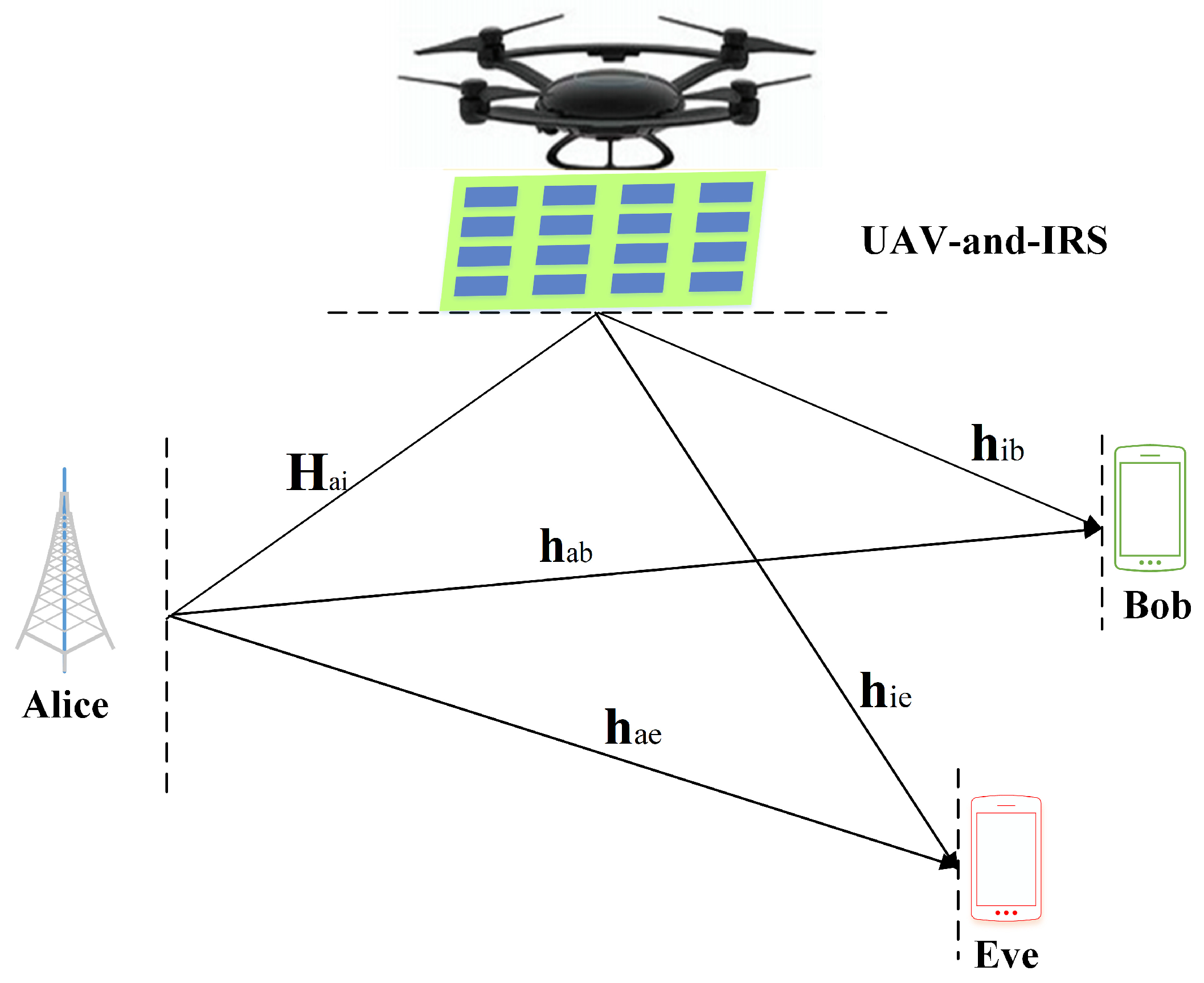
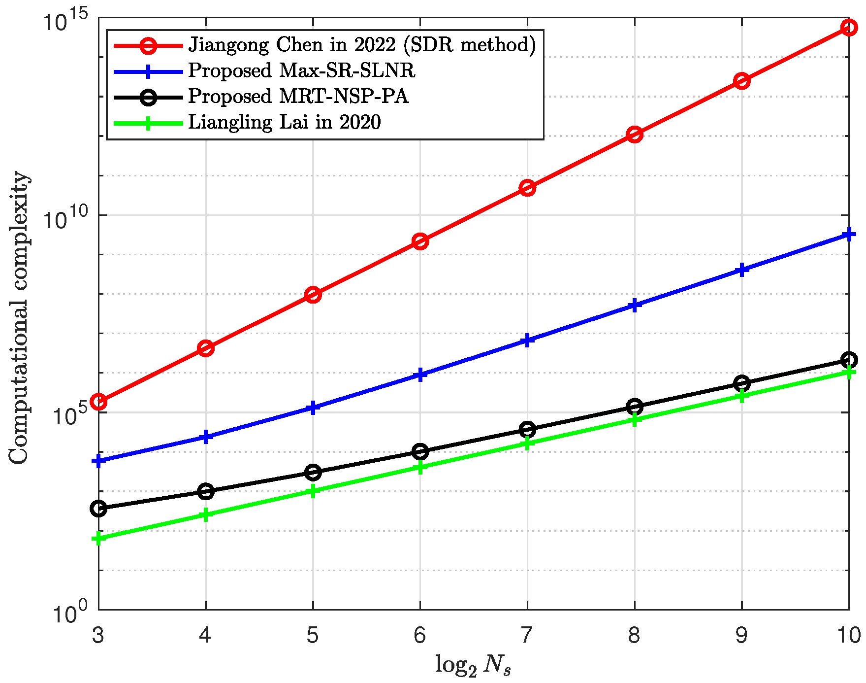
  • The IRS and UAV-aided DM networks were established to transmit a single CM stream by giving full play to the advantages of the DM, UAV, and IRS to improve the SR performance. To obtain a high performance SR, the CM beamforming vector was given by the rule of maximizing the SR (Max-SR), and the method of maximizing the signal-to-leakage-noise ratio (SLNR) in [41] was used to design the PSM of the IRS. The mutual iterative CM beamforming vector and the PSM of the IRS further improved the SR. AN was independently projected on the null-space of other channels, maximizing the interference with Eve through the direct channel. The iterative process was related to the initial value. Therefore, the Max-SR-SLNR method had high computational complexity.
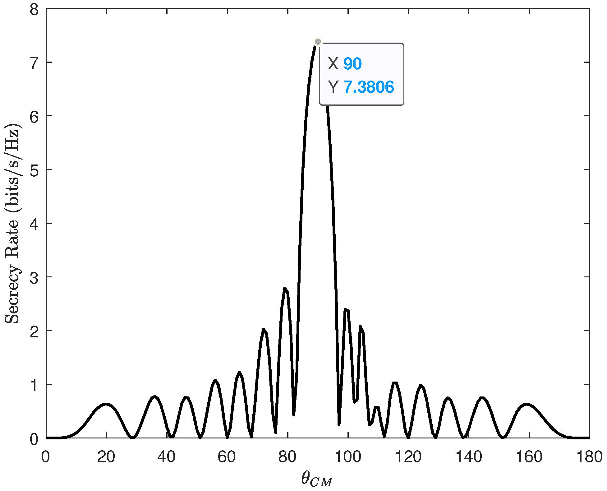
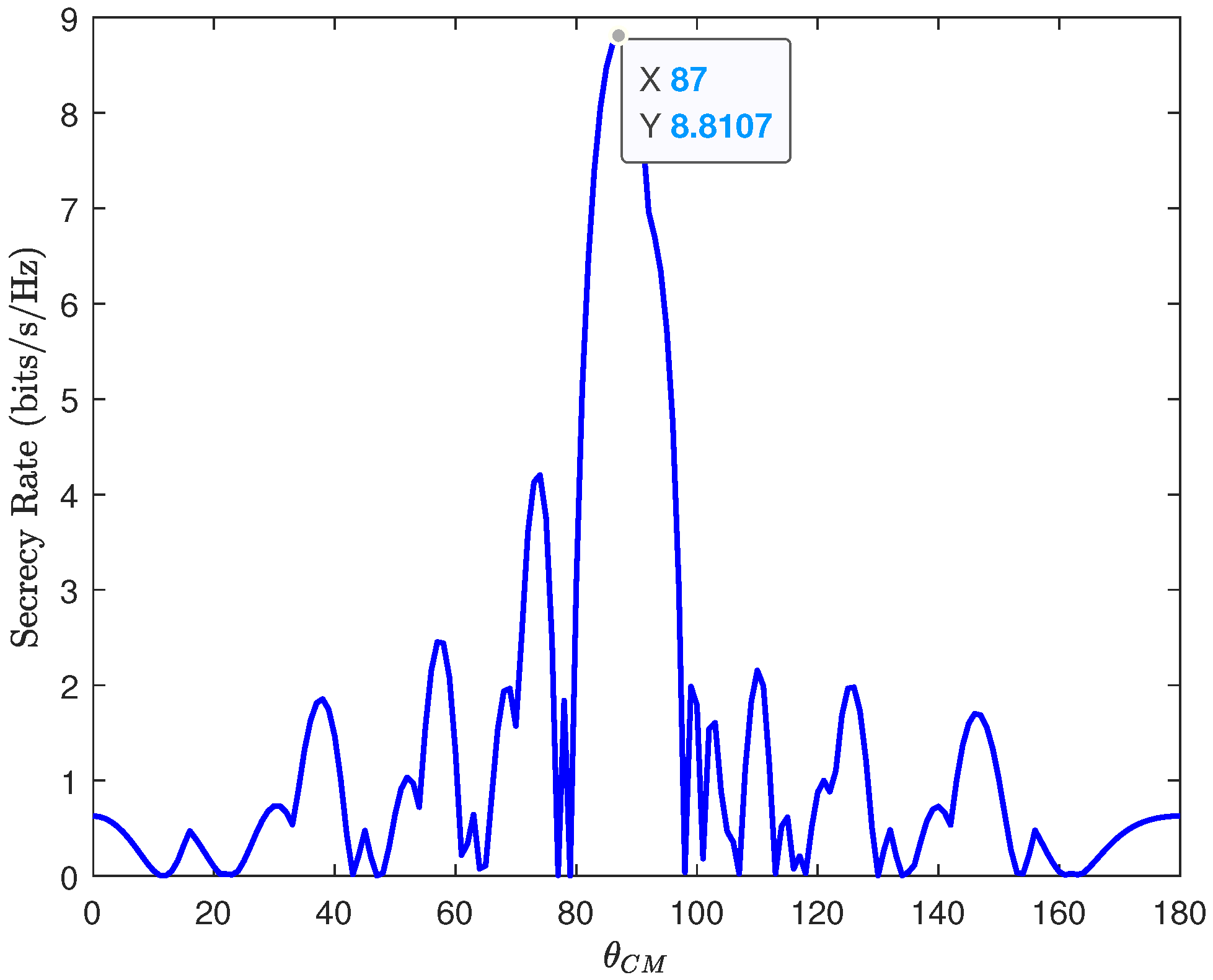
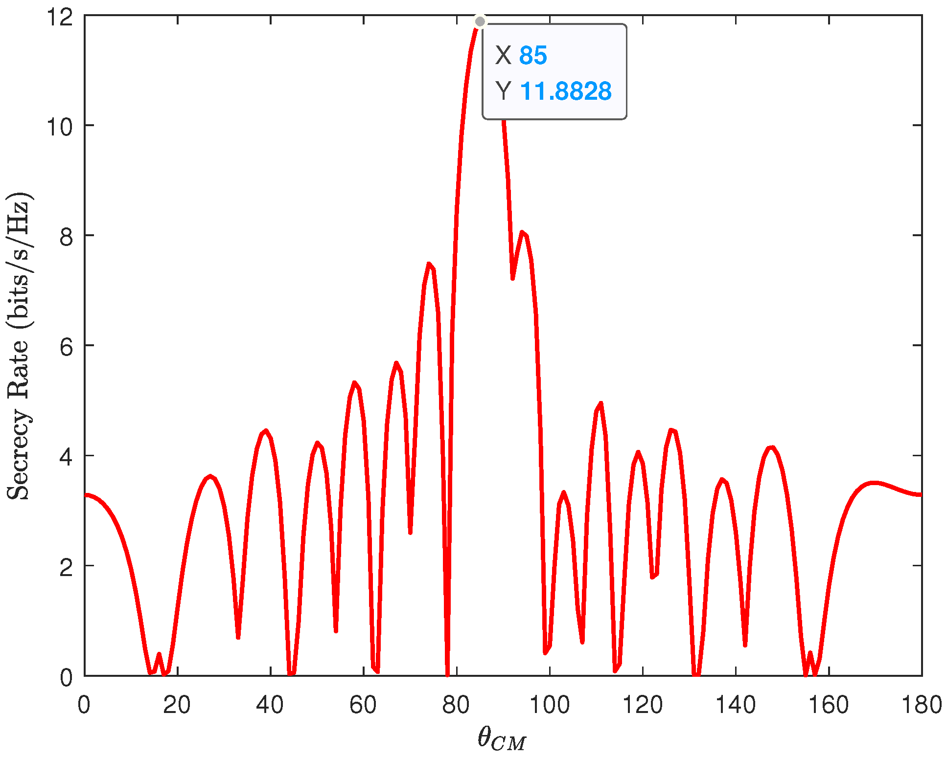
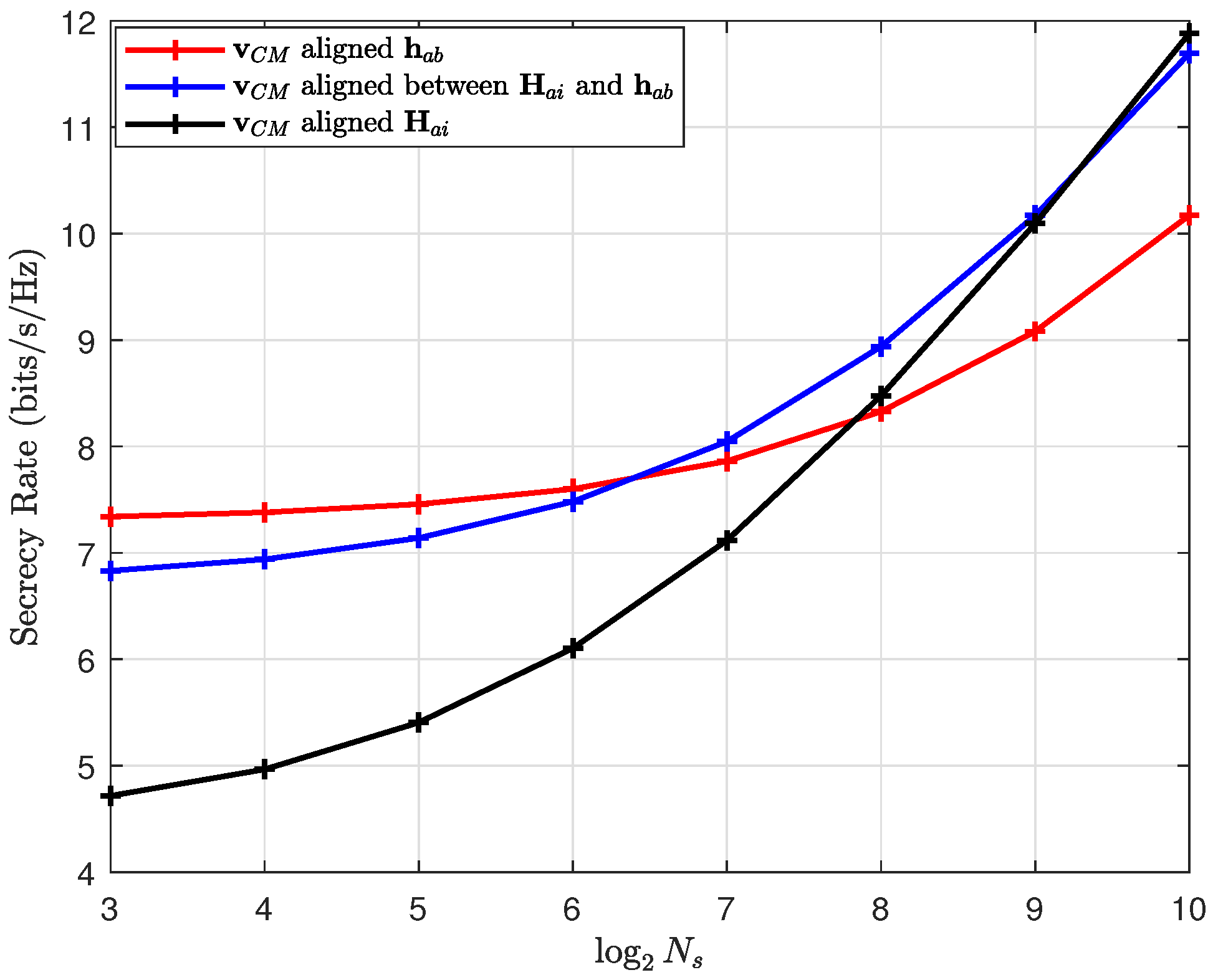
  • To reduce the computational complexity of the Max-SR-SLNR, a maximum ratio transmission (MRT)-based method is proposed. Here, the CM and AN beamforming vectors were constructed by using an MRT and an NSP, respectively, whereas the PSM of the IRS was designed by using the phase alignment (PA) method. It is particularly noted that the three optimization variables (OVs) were designed independently, and the method is called the MRT-NSP-PA. In addition, CM beamforming was only aligned to the Alice-to-IRS channel, ignoring the direct channel, etc. Therefore, the relationship between the direction of the CM beamforming and the number of IRS reflecting elements was observed from simulations. By designing different MRT methods at different IRS scales, the SR performance of the MRT-NSP-PA method was improved at small-scale and medium-scale IRSs.
The structure of this paper is as follows. Section 2 shows the system model of this paper and the derivation of the SR problem under this model. The two designed beamforming methods are presented in Section 3. In Section 4, the numerical simulations and related analyses are presented. In the end, Section 5 draws the conclusions and presents the limitations of the two methods.
Notations: In this paper, bold lowercase and bold uppercase letters represent vectors and matrices, respectively.The notation I N indicates the N × N identity matrix. The sign of E { · } is the expectation operation. The mathematical notations are shown in the following Table 1:
A comparison table to compare the existing works is drawn as Table 2:

2. System Model

As illustrated in Figure 1, an IRS- and UAV-aided DM network is sketched, where the IRS was mounted on a UAV, and the UAV hovered at a suitable height such that the UAV could see Alice, Bob, or both. Alice was a transmitter equipped with N a antennas, Bob and Eve were the legal and illegal receivers equipped with a single antenna, respectively, and the IRS was equipped with N s passive reflecting elements.
The baseband signal sent from Alice is given by
x = β 1 P t v C M s + β 2 P t v A N z ,
where β 1 denotes the power allocation (PA) factor of the CM, β 2 represents the PA factor of the AN, with β 1 + β 2 = 1, P t stands for the transmit power, v C M represents the precoding vector of the CM with v C M C N a × 1 , v A N represents the precoding vector of the AN with v A N C N a × 1 , s represents the CM, with a constraint that E | s | 2 = 1 , and z is the AN with E | z | 2 = 1 .
The signal received at Bob is represented as
y b = g a b h a b H + g a i b h i b H Θ H a i x + n b = g a b β 1 P t h a b H v C M s + g a i b β 1 P t h i b H Θ H a i v C M s + g a b β 2 P t h a b H v A N z + g a i b β 2 P t h i b H Θ H a i v A N z + n b ,
where h a b C N a × 1 , H a i = h θ A I r , φ A I r h H θ A I t , φ A I t C N s × N a , and h i b C N s × 1 represent the Alice-to-Bob, Alice-to-IRS, and IRS-to-Bob channels, respectively. g a b and g a i b = g a i g i b are the path loss coefficients of the Alice-to-Bob direct channel and the cascade channel, respectively. n b C N 0 , σ b 2 is the additive white Gaussian noise (AWGN) at Bob. The phase shifting matrix (PSM) of the IRS is given by
Θ = diag e j ϕ 1 , , e j ϕ m , , e j ϕ N s ,
where ϕ m is the reflected phase of the m-th cell on the IRS, and θ H = ( e j ϕ 1 , , e j ϕ N s ) .
The normalized channel vector can be written as
h ( θ , φ ) = 1 N e j 2 π Φ θ , φ 1 , , e j 2 π Φ θ , φ 2 , , e j 2 π Φ θ , φ N H ,
where the phase shift Φ θ , φ ( n ) is given by
Φ θ , φ ( n ) = d λ n N + 1 2 cos θ cos φ , n = 1 , , N ,
where d is the array element spacing, λ is the carrier wavelength, θ is the angle of departure, and φ is the pitch angle.
Similarly, the signal received at Eve can be given by
y e = g a e h a e H + g a i e h i e H Θ H a i x + n e = g a e β 1 P t h a e H v C M s + g a i e β 1 P t h i b H Θ H a i v C M s + g a e β 2 P t h a e H v A N z + g a i e β 2 P t h i b H Θ H a i v A N z + n e ,
where h a e C N a × 1 and h i e C N s × 1 represent the Alice-to-Eve and the IRS-to-Eve channels, respectively. g a e and g a i e = g a i g i e are the path loss coefficients of the Alice-to-Eve direct channel and the cascade channel, respectively, and n e C N 0 , σ e 2 is the AWGN at Eve.
The signal received at the IRS can be indicated as
y i = H a i x = H a i ( β 1 P t v C M s + β 2 P t v A N z ) .
According to (2), the signal-to-interference plus noise ratio (SINR) of Bob is expressed as
γ b = β 1 P t g a b h a b H v C M + g a i b h i b H Θ H a i v C M 2 β 2 P t g a b h a b H v A N + g a i b h i b H Θ H a i v A N 2 + σ b 2 .
In terms of (6), the SINR of Eve is written as
γ e = β 1 P t g a e h a e H v C M + g a i e h i e H Θ H a i v C M 2 β 2 P t g a e h a e H v A N + g a i e h i e H Θ H a i v A N 2 + σ e 2 .
The corresponding rates of Bob and Eve are expressed as
R b = log 2 1 + γ b ,
and
R e = log 2 1 + γ e ,
respectively; hence, the calculation of the SR proceeds as follows:
R s = R b R e + = log 2 1 + γ b 1 + γ e ,
where [ x ] + max { 0 , x } .

3. The Proposed Beamforming Methods: Max-SR-SLNR and MRT-NSP-PA

In this section, two beamforming methods, called the Max-SR-SLNR and MRT-NSP-PA, are proposed in the IRS- and UAV-assisted DM network. To further enhance the SR of the MRT-NSP-PA, the relationship between the direction of the CM beamforming and N s is explored.

3.1. The Proposed Max-SR-SLNR

First, we optimized the AN beamforming vector, which is independent of Θ and v C M . Alice projects the v A N on the null space of other channels and maximizes the received AN power along the Alice-to-Eve direct channel at Eve. The design of the v A N is written as the following equation
max v A N v A N H h a e h a e H v A N
such that h a b H a i H H v A N = 0 , v A N H v A N = 1 .
Let us define
P = h a b H a i H H .
According to the first constraint of (13), v A N can be rewritten as
v A N = I N a P H P P H P u A N ,
where u A N is a new optimization variable with u A N H u A N = 1 . Let us define
T = I N P H P P H P .
Therefore, (13) can be simplified as
max u A N u A N H T H h a e h a e H T u A N
  such that u A N H u A N = 1 .
Since the matrix T is a matrix of rank-one, v A N can be expressed as
v A N = T a e h a e T a e h a e .
Next, we designed the alternating iterative optimization problem with two variables, v C M and Θ . The optimization problem with the criterion of maximizing the SR can be expressed as
max v C M , Θ R s v C M , Θ
such that v C M H v C M = 1 , θ H θ = N s .
The SINR of Bob can be re-expressed as follows
γ b = v C M H h b 1 h b 1 H v C M v A N H h b 2 h b 2 H v A N + σ b 2 ,
where
h b 1 H = β 1 P t g a b h a b H + β 1 P t g a i b h i b H Θ H a i , h b 2 H = β 2 P t g a b h a b H + β 2 P t g a i b h i b H Θ H a i .
Accordingly, the rate of Bob can be rewritten as
R b = log 2 1 + v C M H h b 1 h b 1 H v C M v A N H h b 2 h b 2 H v A N + σ b 2 .
Similarly, the SINR of Eve can be rewritten as
γ e = v C M H h e 1 h e 1 H v C M v A N H h e 2 h e 2 H v A N + σ e 2 ,
where
h e 1 H = β 1 P t g a e h a e H + β 1 P t g a i e h i e H Θ H a i , h e 2 H = β 2 P t g a e h a e H + β 2 P t g a i e h i e H Θ H a i .
Therefore, the rate of Eve can be expressed as follows
R e = log 2 1 + v C M H h e 1 h e 1 H v C M v A N H h e 2 h e 2 H v A N + σ e 2 .
According to (22) and (25), we designed the CM beamforming vectors using the criterion of maximizing the SR, and (19) can be transformed into
max v C M v C M H ( a + σ b 2 ) I N a + h b 1 h b 1 H v C M v C M H ( b + σ e 2 ) I N a + h e 1 h e 1 H v C M
such that v C M H v C M = 1 ,
where a = v A N H h b 2 h b 2 H v A N , and b = v A N H h e 2 h e 2 H v A N .
Accordingly, the Rayleigh–Ritz ratio theorem can be used, and v C M is the eigenvector corresponding to the largest eigenvalue of the following formula
( b + σ e 2 ) I N a + h e 1 h e 1 H 1 ( a + σ b 2 ) I N a + h b 1 h b 1 H .
The signal-to-leakage-noise ratio (SLNR) method was designed as the PSM of the IRS [41] as follows
  max θ SLNR ( θ )
such that θ H θ = N s ,
where the objective function of (28) is
SLNR ( θ ) = h i b H Θ H a i v C M v C M H H a i H Θ h i b h i e H Θ H a i v C M v C M H H a i H Θ h i e + σ e 2 .
One obtains
diag { a } b = diag { b } a ,
where a C N s × 1 , and b C N s × 1 . Therefore, the objective function of (28) can be expressed as
θ H A θ θ H B θ ,
where A = diag H a i v C M h i b h i b H diag H a i v C M , and B = diag H a i v C M h i e h i e H diag H a i v C M + σ e 2 N s I N s .
Accordingly, the Rayleigh–Ritz ratio theorem can be used, and θ can be obtained by the following formula
B 1 A .
Let us define the eigenvector corresponding to the largest eigenvalue of (32) as u . Since Θ has a constant mode constraint, Θ can be given by
Θ = diag ( e j   arg   u ) .
We designed the v C M , v A N , and PSM of the IRS. It is particularly noted that the v A N is independent of the v C M and PSM of the IRS, while v C M and the PSM of the IRS are mutually coupled. Therefore, it is necessary to alternately optimize the v C M and Θ until R s ( p ) R s ( p 1 ) ϵ , where p represents the total number of iterations, and the optimal v C M and Θ can be iterated. The whole iterative process is listed in Algorithm 1.
Algorithm 1 Proposed Max-SR-SLNR method
1:
Set initial solution Θ ( 0 ) , v C M ( 0 ) , and v A N . Random multiple phases of θ , and calculate the initial R s ( 0 ) .
2:
Set p = 0, threshold ϵ .
3:
repeat
4:
   Given ( Θ ( p ) , v A N ), according to (27) to obtain v C M ( p + 1 ) .
5:
   Given ( v C M ( p + 1 ) , v A N ), according to (33) to obtain Θ ( p + 1 ) .
6:
   Compute R s ( p + 1 ) using v C M ( p + 1 ) , v A N and Θ ( p + 1 ) .
7:
   p = p+1;
8:
until   R s p R s p 1 ϵ , and record the maximum SR value.
The computational complexity of the Max-SR-SLNR method is
O ( D 1 ( D 2 ( N s 3 + 7 N s 2 + 8 N a N s 2 N s 2 + 2 N a 3 + 4 N a 2 ) + 2 N a 2 + N a 1 ) )
float-point operations (FLOPs), where D 1 and D 2 represent the iterative numbers of the optimization variables v C M and Θ .

3.2. The Proposed MRT-NSP-PA

In the above subsection, the iterative optimization process between variables v C M and θ led to a high computational complexity. In order to reduce the complexity of the Max-SR-SLNR, a low-complexity MRT-NSP-PA method is presented in which the three variables v C M , v A N , and θ were designed independently as follows.
Let us define
h a i = h H θ A I t .
First, the MRT method was used to design v C M . Taking the transmit power limit into account, the final CM beamforming vector can be directly given by
v C M = h a i h a i .
In the same manner, the AN beamforming method based on the MRT and NSP is
v A N = T a e h a e T a e h a e .
Next, we designed the IRS phase matrix Θ , which was completely different to the Max-SR-SLNR method. The received CM power via the cascaded path at Bob is equal to
P b = β 1 P t g a i b v C M H H a i H Θ H h i b h i b H Θ H a i v C M .
Equation (38) can be rewritten as
P b = β 1 P t g a i b θ H diag H a i v C M h i b ·
h i b H diag H a i v C M θ .
To maximize the received CM power along the cascaded path from Alice to Bob via the IRS at Bob, the PA method directly gives the value of θ as follows:
θ = e j arg h i b H diag H a i v C M H .
The complexity of this MRT-NSP-PA method is
𝒪 2 N s 2 + 2 N a N s 2 N s + 4 N a + 2 N a 2 2
FLOPs.
From (34) and (42), it can be noticed that the computational complexity of the Max-SR-SLNR method was higher than that of the MRT-NSP-PA method. Because the beamforming vectors of the MRT-NSP-PA method were designed as closed form solutions, they have the advantage of low computational complexity. However, there was some performance loss of the SR in the MRT-NSP-PA method. Of the two methods, the MRT-NSP-PA method was more feasible. This is because in the MRT-NSP-PA algorithm, the CM, the AN beamforming vector, and the PSM of the IRS were designed as closed form solutions.
In the above, the CM beamforming was only phase-aligned to the Alice-to-IRS channel, ignoring the direct path to the desired user Bob, etc. Therefore, designing the CM beamforming in this case led to performance loss. In order to explore the CM beamforming direction on the SR performance, we explored the relationship between the number of IRS reflecting elements and the direction of the CM beamforming. Thus, the CM beamforming was allowed to rotate in the angle range [ 0 , π ] . In this case, the direction of the CM beamforming θ C M is written as
θ C M [ 0 , π ] .
In what follows, we adopted three methods to design v C M :
v C M = h a b h a b ,
v C M = ( h a i + h a b ) ( h a i + h a b ) ,
and
v C M = h a i h a i .

4. Simulation and Analysis

The numeral results to examine the SR performance and computational complexities of proposed algorithms are provided herein. The simulation parameters are set as Table 3.
After setting the 3D coordinates of the IRS and UAV, Bob, Eve, and Alice, their corresponding 2D coordinates can be obtained so that the departure angles and distances can be obtained. In turn, the channel state information of each channel can be determined. In the following, our two proposed methods are compared with two benchmark schemes:
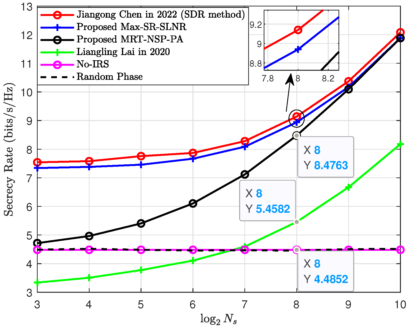
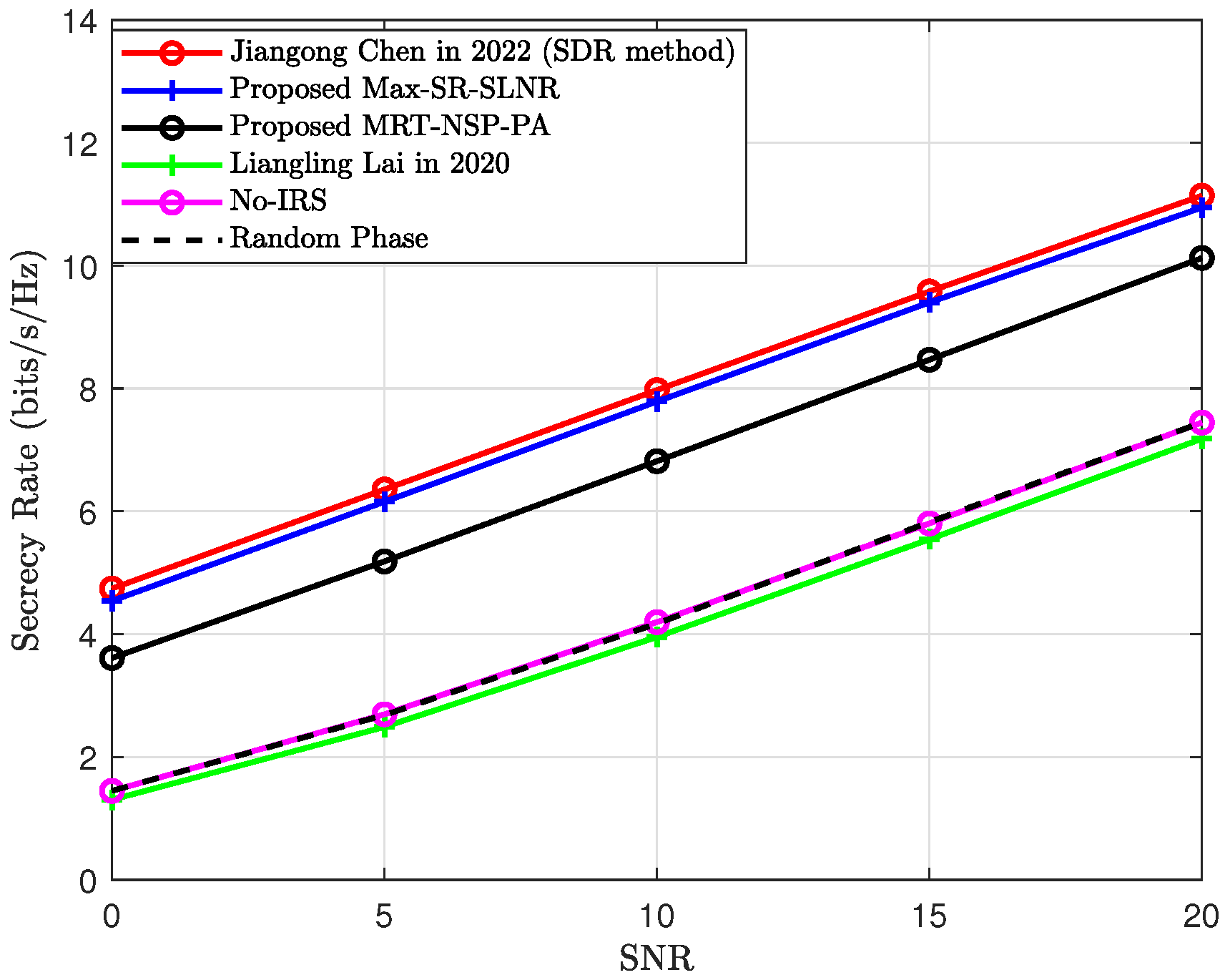
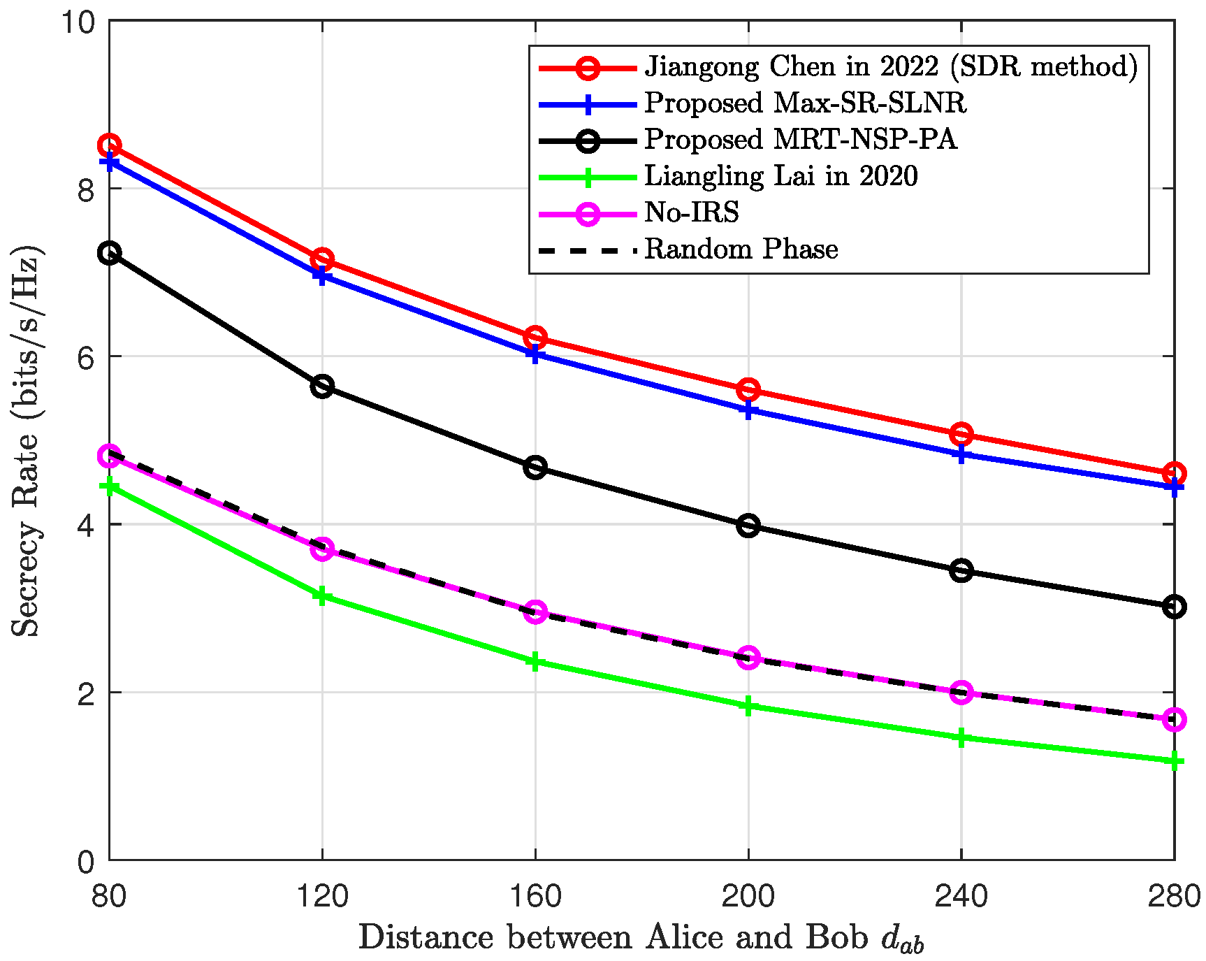
  • No IRS: This scheme disregards the presence of the IRS. Θ = 0 N s × N s .
  • Random Phase: Here, the IRS phase shift value takes on a random value, and the phase of the IRS is random within the range [ 0 , 2 π ) .
Figure 2 shows that SR versus N s . The SR performance of the Max-SR-SLNR and MRT-NSP-PA was much higher than the cases of the no IRS, random phase, and the existing method in [36] and gradually increased with N s . Their SR performance was ordered from the best to the worst as follows: the SDR in [37], the Max-SR-SLNR, the MRT-NSP-PA, and the existing method in [36]. The SR performance gap between the Max-SR-SLNR and the SDR in [37] was small. When N s was 256, the existing method in [36], the MRT-NSP-PA method, the Max-SR-SLNR method, and the SDR in [37] had a higher SR than the random phase and no IRS: 18%, 47%, 50%, and 53%, respectively. The SR of the Max-SR-SLNR method was much higher than the MRT-NSP-PA method when the IRS was small- to medium-scale. For the case of a large scale, the latter approached the Max-SR-SLNR. The application scenario of this conclusion was that the departure angle from Alice to IRS had a certain angular separation from the departure angle from Alice to Bob.
Figure 3 plots the SR versus the SNR for N s = 128. As can be seen from the simulation diagram, the SR performance of the six schemes increased with the increase in the SNR. The SR performance of the proposed MRT-NSP-PA method and the Max-SR-SLNR method was about two times that of the existing methods in [36]. When SNR = 10 dB, compared with the cases of the no IRS and the random phase, the SDR in [37], the Max-SR-SLNR method, and the MRT-NSP-PA method achieved SR improvements of roughly: 47%, 46%, and 34%, respectively. Therefore, this means that effectively designing the PSM of the IRS, CM, and AN beamforming can harvest obvious performance gains.
Figure 4 shows the SR versus the distance between Alice and Bob for N s = 100. It can be observed that as the d a b increased, the SRs in all cases tended to decrease. This is because increasing the d a b increased the path loss. It can be seen from Figure 4 that the SR of the existing method in [36] was only half of the SR performance of the Max-SR-SLNR and MRT-NSP-PA method, thus demonstrating the advantages of our proposed methods.
Figure 5, Figure 6 and Figure 7 illustrate the SR versus directional angle of the CM beamforming with different numbers of IRS elements as follows: 16, 256, and 1024. With the increase in N s , the directional angle of the CM beamforming constantly changed from 0 to π . When N s = 16, the SR was the highest when the CM beamforming was transferred to the direct channel from h a b . When N s = 256, the CM beamforming was directed to the middle of the H a i channel and the h a b channel. When N s = 1024, the SR was the highest when the CM beamforming was aimed at the Alice-to-IRS channel. These results were mainly due to the fact that the Alice-to-Bob direct channel dominated in the case of the small-scale IRS, whereas the cascaded channel via Alice, the IRS, and Bob dominated for the large-scale scenario.
Based on the inspiration of Figure 5, Figure 6 and Figure 7, we propose three different MRT methods for designing CM beamforming vectors. In Figure 8, the SR versus N s is plotted for the various MRT methods. The figure shows that the three methods had different advantages under different numbers of IRS elements. When N s ranged from 8 to 64, v C M was aligned with the h a b channel to achieve the best SR performance. When N s varied from 64 to 512, v C M was aligned with the channel between h a b and H a i to achieve the best SR performance. When N s changed from 512 to 1024 (i.e., under hyperscale), v C M was aligned with the H a i channel to achieve the best SR performance.
Figure 9 plots the computational complexity versus N s . Figure 9 shows that there was an increasing order in complexity (FLOPs): the existing method in [36] ( 𝒪 ( N 2 ) FLOPs), the MRT-NSP-PA ( 𝒪 ( N 2 ) FLOPs), the Max-SR-SLNR ( 𝒪 ( N 3 ) FLOPs), and the SDR in [37] ( 𝒪 ( N 4.5 ) FLOPs). The MRT-NSP-PA was at least one and two orders of magnitude lower than the Max-SR-SLNR for the small-scale and large-scale IRS, respectively. Moreover, as N s increased, the complexity gradually and linearly rose. From Figure 2 and Figure 9, it can be seen that the two methods proposed in this paper had higher SRs than the method in [36]. In addition, the gap in the SR performance between the Max-SR-SLNR method and the SDR method in [37] was small, and the computational complexity of the Max-SR-SLNR method was much lower than the SDR method in [37]. Thus, the two methods proposed in this paper have their own advantages in terms of the SR performance and computational complexity.

Discussion of the Results

As shown in Figure 2, Figure 3, Figure 4, Figure 5, Figure 6, Figure 7, Figure 8 and Figure 9, the advantages and disadvantages of the proposed methods in this paper compared with existing methods were analyzed by several performance indicators. The gap in the SR performance between the Max-SR-SLNR method and the SDR method in [37] was small, and the computational complexity of the Max-SR-SLNR was much lower than the SDR in [37]. To further improve the SR performance of the MRT-NSP-PA method, the relationship between the orientation of the CM beamforming and N s was explored. By changing the orientation of the CM beamforming, the MRT-NSP-PA method not only had the advantage of a high SR performance but also low complexity.

5. Conclusions and Limitations

5.1. Conclusions

In this paper, we presented the design of the beamforming of an IRS- and UAV-aided DM network in order to fully exploit the SR performance benefit from an IRS and a UAV. Two beamforming methods, called Max-SR-SLNR and MRT-NSP-PA, were proposed. The simulations in Section 4 indicated that the Max-SR-SLNR and MRT-NSP-PA achieved an obvious SR performance gain over the no IRS and random phase, especially in the large-scale IRS. Moreover, the SR gains harvested by the two methods increased gradually as N s increased. In the small-scale and medium-scale IRSs, the proposed Max-SR-SLNR method was better than the MRT-NSP-PA method in terms of the SR, and the latter approached the former as the IRS moved to a larger scale. However, the latter was at least one to two orders of magnitude lower than the former when the IRS size ranged from small to large. In addition, the proposed Max-SR-SLNR and MRT-NSP-PA struck a good balance between the rate performance and the complexity.

5.2. Limitations

The two methods proposed in this paper, the Max-SR-SLNR and the MRT-NSP-PA, did not jointly optimize the v A N , v C M , and θ with the criterion of maximizing the SR. Therefore, the SR performance of both methods was not optimal. In addition, the power allocation (PA) factors β 1 and β 2 were fixed in the simulation parameters. If the PA factors were optimized, the SR of the system could be further enhanced.

Author Contributions

Y.L. surveyed the algorithms based on the system and performed the simulations. Y.Z., R.D., J.L. and X.C. surveyed the directional modulation network, and the UAV- and IRS-aided directional modulation network. F.S. revised the paper and proposed the algorithms. Y.W. and S.Y. surveyed the IRS- and UAV-aided network. J.W. reviewed and edited the article. All authors have read and agreed to the published version of the manuscript.

Funding

This work was supported in part by the National Natural Science Foundation of China (Nos. U22A2002, 62071234, and 61972093), the Hainan Province Science and Technology Special Fund (ZDKJ2021022), the Scientific Research Fund Project of Hainan University under Grant KYQD(ZR)-21008, and the Fujian University Industry University Research Joint Innovation Project (No. 2022H6006).

Data Availability Statement

There are no data presented in the article.

Acknowledgments

We thank the editor and the reviewers for their valuable comments.

Conflicts of Interest

The authors of the article have no conflict of interest.

Abbreviations

The abbreviations used in the article are as follows:
UAVUnmanned aerial vehicle
LoSLine of sight
IRSIntelligent reflecting surface
DMDirectional modulation
SINRSignal-to-interference plus noise ratio
PAPhase alignment
SLNRSignal-to-leakage-noise ratio
SRSecrecy rate
Max-SR-SLNRMaximum SR-SLNR
NSPNull-space projection
MRTMaximum ratio transmission
PSMPhase shift matrix
ANArtificial noise
CMConfidential message
PLPath loss

References

  1. Xiao, Z.; Xia, P.; Xia, X.G. Enabling UAV cellular with millimeter-wave communication: Potentials and approaches. IEEE Commun. Mag. 2016, 54, 66–73. [Google Scholar] [CrossRef] [Green Version]
  2. Azari, M.M.; Geraci, G.; Garcia-Rodriguez, A.; Pollin, S. UAV-to-UAV communications in cellular networks. IEEE Trans. Wirel. Commun. 2020, 19, 6130–6144. [Google Scholar] [CrossRef]
  3. Zeng, Y.; Zhang, R.; Lim, T.J. Wireless communications with unmanned aerial vehicles: Opportunities and challenges. IEEE Commun. Mag. 2016, 54, 36–42. [Google Scholar] [CrossRef] [Green Version]
  4. Zhao, M.M.; Shi, Q.; Zhao, M.J. Efficiency maximization for UAV-enabled mobile relaying systems with laser charging. IEEE Trans. Wirel. Commun. 2020, 19, 3257–3272. [Google Scholar] [CrossRef] [Green Version]
  5. Wen, F.; Shi, J.; Gui, G.; Gacanin, H.; Dobre, O.A. 3-D Positioning Method for Anonymous UAV Based on Bistatic Polarized MIMO Radar. IEEE Internet Things J. 2022, 10, 815–827. [Google Scholar] [CrossRef]
  6. Csiszar, I.; Korner, J. Broadcast channels with confidential messages. IEEE Trans. Inf. Theory 1978, 24, 339–348. [Google Scholar] [CrossRef] [Green Version]
  7. Mukherjee, A.; Fakoorian, S.A.A.; Huang, J.; Swindlehurst, A.L. Principles of physical layer security in multiuser wireless networks: A survey. IEEE Commun. Surv. Tutor. 2014, 16, 1550–1573. [Google Scholar] [CrossRef] [Green Version]
  8. Yang, N.; Yeoh, P.L.; Elkashlan, M.; Schober, R.; Yuan, J. MIMO wiretap channels: Secure transmission using transmit antenna selection and receive generalized selection combining. IEEE Commun. Lett. 2013, 17, 1754–1757. [Google Scholar] [CrossRef]
  9. Hamamreh, J.M.; Furqan, H.M.; Arslan, H. Classifications and applications of physical layer security techniques for confidentiality: A comprehensive survey. IEEE Commun. Surv. Tutor. 2019, 21, 1773–1828. [Google Scholar] [CrossRef]
  10. Yang, N.; Yan, S.; Yuan, J.; Malaney, R.; Subramanian, R.; Land, I. Artificial noise: Transmission optimization in multi-input single-output wiretap channels. IEEE Trans. Commun. 2015, 63, 1771–1783. [Google Scholar] [CrossRef]
  11. Diffie, W.; Hellman, M.E. New directions in cryptography. IEEE Trans. Inform. Theory 1976, 22, 644–654. [Google Scholar] [CrossRef] [Green Version]
  12. Wyner, A.D. The wire-tap channel. Bell Syst. Tech. J. 1975, 54, 1355–1387. [Google Scholar] [CrossRef]
  13. Sarkar, M.Z.I.; Ratnarajah, T. Secure communications through Rayleigh fading SIMO channel with multiple eavesdroppers. In Proceedings of the 2010 IEEE International Conference on Communications, Cape Town, South Africa, 23–27 May 2010; pp. 1–5. [Google Scholar]
  14. Khisti, A.; Tchamkerten, A.; Wornell, G.W. Secure broadcasting over fading channels. IEEE Trans. Inf. Theory 2008, 54, 2453–2469. [Google Scholar] [CrossRef] [Green Version]
  15. Ju, Y.; Wang, H.M.; Zheng, T.X.; Yin, Q.; Lee, M.H. Safeguarding millimeter wave communications against randomly located eavesdroppers. IEEE Trans. Wirel. Commun. 2018, 17, 2675–2689. [Google Scholar] [CrossRef] [Green Version]
  16. Shu, F.; Wu, X.; You, X.; Lu, J.; Hu, J.; Zhu, W.; Yu, H.; Xu, Z.; Chen, R. Directional modulation-based secure wireless transmission: Basic principles, key techniques, and applications. Sci. Sin. Inform. 2017, 47, 1209–1225. [Google Scholar]
  17. Hu, J.; Shu, F.; Li, J. Robust synthesis method for secure directional modulation with imperfect direction angle. IEEE Commun. Lett. 2016, 20, 1084–1087. [Google Scholar] [CrossRef]
  18. Qiu, B.; Tao, M.; Wang, L.; Xie, J.; Wang, Y. Multi-beam directional modulation synthesis scheme based on frequency diverse array. IEEE Trans. Inf. Forensics Secur. 2019, 14, 2593–2606. [Google Scholar] [CrossRef]
  19. Mamaghani, M.T.; Hong, Y. On the performance of low-altitude UAV-enabled secure AF relaying with cooperative jamming and SWIPT. IEEE Access 2019, 7, 153060–153073. [Google Scholar] [CrossRef]
  20. Sun, X.; Yang, W.; Cai, Y.; Xiang, Z.; Tang, X. Secure transmissions in millimeter wave SWIPT UAV-based relay networks. IEEE Wireless Commun. Lett. 2019, 8, 785–788. [Google Scholar] [CrossRef]
  21. Shu, F.; Xu, L.; Wang, J.; Zhu, W.; Xiaobo, Z. Artificial-noise-aided secure multicast precoding for directional modulation systems. IEEE Trans. Veh. Technol. 2018, 67, 6658–6662. [Google Scholar] [CrossRef] [Green Version]
  22. Shu, F.; Wu, X.; Hu, J.; Li, J.; Chen, R.; Wang, J. Secure and precise wireless transmission for random-subcarrier-selection-based directional modulation transmit antenna array. IEEE J. Sel. Areas Commun. 2018, 36, 890–904. [Google Scholar] [CrossRef]
  23. Li, C.; Wang, X.; Yang, L.; Zhu, W.P. A joint source and relay power allocation scheme for a class of MIMO relay systems. IEEE Trans. Signal Process 2009, 57, 4852–4860. [Google Scholar]
  24. Wu, Q.; Zhang, R. Beamforming optimization for wireless network aided by intelligent reflecting surface with discrete phase shifts. IEEE Trans. Commun. 2019, 68, 1838–1851. [Google Scholar] [CrossRef] [Green Version]
  25. Dong, R.; Teng, Y.; Sun, Z.; Zou, J.; Huang, M.; Li, J.; Shu, F.; Wang, J. Performance Analysis of Wireless Network Aided by Discrete-Phase-Shifter IRS. J. Commun. Netw. 2022, 24, 603–612. [Google Scholar] [CrossRef]
  26. Tang, W.; Chen, M.Z.; Chen, X.; Dai, J.Y.; Han, Y.; Di Renzo, M.; Zeng, Y.; Jin, S.; Cheng, Q.; Cui, T.J. Wireless communications with reconfigurable intelligent surface: Path loss modeling and experimental measurement. IEEE Trans. Wirel. Commun. 2020, 20, 421–439. [Google Scholar] [CrossRef]
  27. Wu, Q.; Zhang, R. Intelligent reflecting surface enhanced wireless network via joint active and passive beamforming. IEEE Trans. Wirel. Commun. 2019, 18, 5394–5409. [Google Scholar] [CrossRef] [Green Version]
  28. Hum, S.V.; Perruisseau-Carrier, J. Reconfigurable reflectarrays and array lenses for dynamic antenna beam control: A review. IEEE Trans. Antennas Propag. 2013, 62, 183–198. [Google Scholar] [CrossRef] [Green Version]
  29. Han, Y.; Zhang, S.; Duan, L.; Zhang, R. Double-IRS aided MIMO communication under LoS channels: Capacity maximization and scaling. IEEE Trans. Commun. 2022, 70, 2820–2837. [Google Scholar] [CrossRef]
  30. Pan, C.; Ren, H.; Wang, K.; Xu, W.; Elkashlan, M.; Nallanathan, A.; Hanzo, L. Multicell MIMO communications relying on intelligent reflecting surfaces. IEEE Trans. Wirel. Commun. 2020, 19, 5218–5233. [Google Scholar] [CrossRef]
  31. Wang, X.; Zhang, P.; Shu, F.; Shi, W.; Wang, J. Power Allocation for IRS-aided Two-way Decode-and-Forward Relay Wireless Network. IEEE Trans. Veh. Technol. 2023, 72, 1337–1342. [Google Scholar] [CrossRef]
  32. Zhou, X.; Yan, S.; Wu, Q.; Shu, F.; Ng, D.W.K. Intelligent reflecting surface (IRS)-aided covert wireless communications with delay constraint. IEEE Trans. Wirel. Commun. 2022, 21, 532–547. [Google Scholar] [CrossRef]
  33. Shi, W.; Zhou, X.; Jia, L.; Wu, Y.; Shu, F.; Wang, J. Enhanced secure wireless information and power transfer via intelligent reflecting surface. IEEE Commun. Lett. 2020, 25, 1084–1088. [Google Scholar] [CrossRef]
  34. Shu, F.; Yang, L.; Jiang, X.; Cai, W.; Shi, W.; Huang, M.; Wang, J.; You, X. Beamforming and transmit power design for intelligent reconfigurable surface-aided secure spatial modulation. IEEE J. Sel. Topics Signal Process. 2022, 16, 933–949. [Google Scholar] [CrossRef]
  35. Pang, X.; Zhao, N.; Tang, J.; Wu, C.; Niyato, D.; Wong, K.K. IRS-assisted secure UAV transmission via joint trajectory and beamforming design. IEEE Trans. Commun. 2021, 70, 1140–1152. [Google Scholar] [CrossRef]
  36. Lai, L.; Hu, J.; Chen, Y.; Zheng, H.; Yang, N. Directional modulation-enabled secure transmission with intelligent reflecting surface. In Proceedings of the 2020 IEEE 3rd International Conference on Information Communication and Signal Processing (ICICSP), Shanghai, China, 12–15 September 2020; pp. 450–453. [Google Scholar]
  37. Chen, J.; Xiao, Y.; Lei, X.; Niu, H.; Yuan, Y. Artificial noise aided directional modulation via reconfigurable intelligent surface: Secrecy guarantee in range domain. IET Commun. 2022, 16, 1558–1569. [Google Scholar] [CrossRef]
  38. Shu, F.; Teng, Y.; Li, J.; Huang, M.; Shi, W.; Li, J.; Wu, Y.; Wang, J. Enhanced secrecy rate maximization for directional modulation networks via IRS. IEEE Trans. Commun. 2021, 69, 8388–8401. [Google Scholar] [CrossRef]
  39. Dong, R.; Jiang, S.; Hua, X.; Teng, Y.; Shu, F.; Wang, J. Low-Complexity Joint Phase Adjustment and Receive Beamforming for Directional Modulation Networks via IRS. IEEE Open J. Commun. Soc. 2022, 3, 1234–1243. [Google Scholar] [CrossRef]
  40. Wang, R.; Talgat, A.; Kishk, M.A.; Alouini, M.S. Conditional Contact Angle Distribution in LEO Satellite-Relayed Transmission. IEEE Commun. Lett. 2022, 26, 2735–2739. [Google Scholar] [CrossRef]
  41. Sadek, M.; Tarighat, A.; Sayed, A.H. A leakage-based precoding scheme for downlink multi-user MIMO channels. IEEE Trans. Wirel. Commun. 2007, 6, 1711–1721. [Google Scholar] [CrossRef]
Figure 1. System model drawing of an IRS- and UAV-aided DM network.
Drones 07 00489 g001
Figure 2. Secrecy rate versus the number of IRS elements. (name in year is the comparison method).
Drones 07 00489 g002
Figure 3. Secrecy rate versus the SNR.
Drones 07 00489 g003
Figure 4. Secrecy rate versus the distance between Alice and Bob.
Drones 07 00489 g004
Figure 5. Secrecy rate versus θ C M .
Drones 07 00489 g005
Figure 6. Secrecy rate versus θ C M .
Drones 07 00489 g006
Figure 7. Secrecy rate versus θ C M .
Drones 07 00489 g007
Figure 8. Secrecy rate versus N s .
Drones 07 00489 g008
Figure 9. Computational complexity versus N s .
Drones 07 00489 g009
Table 1. Explanation of mathematical symbols.
Conjugate TransposeInversePseudo-InverseTwo-NormDiagonal Operator
( · ) H ( · ) 1 ( · ) · diag ( · )
Table 2. A comparison table with previous works.
Previous WorkAim of the MethodStrong PointLimitation
Existing method in [36]Boost SRLow complexityPoor SR
SDR in [37]Maximize SRHigh SRHigh complexity
Table 3. Table of simulation parameters.
ParameterValue
Alice coordinate(0, 0, 0) m
IRS and UAV coordinate(39.8, 3.5, 3.5) m
Bob coordinate(90, 0, 0) m
Eve coordinate(96.6, −25.9, 0) m
Transmitting power, P s 30 dBm
Noise power, σ b 2 and σ e 2 −40 dBm
PA factor, β 1 0.8
distance of Alice-to-IRS, d a i 40 m
distance of Alice-to-Bob, d a b 90 m
distance of Alice-to-Eve, d a e 100 m
angle of departure of Alice-to-IRS 17 π / 36
angle of departure of Alice-to-Bob 1 π / 2
angle of departure of Alice-to-Eve 7 π / 12
Disclaimer/Publisher’s Note: The statements, opinions and data contained in all publications are solely those of the individual author(s) and contributor(s) and not of MDPI and/or the editor(s). MDPI and/or the editor(s) disclaim responsibility for any injury to people or property resulting from any ideas, methods, instructions or products referred to in the content.

