


MCST Scheme for UAV Systems over LoRa Networks


Abstract
1. Introduction
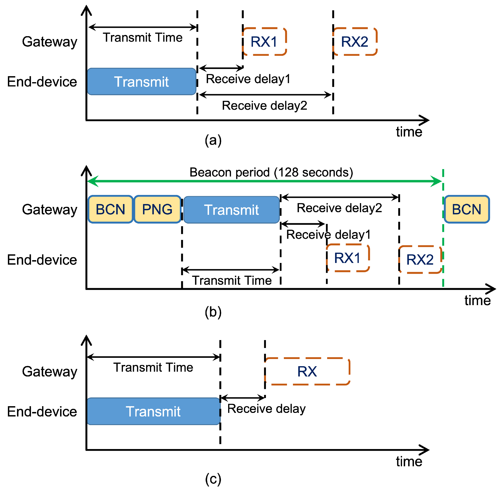
2. LoRaWAN Network Architecture
- It is possible to utilize the MCST scheme and the optimal throughput with minimum latency and energy consumption can be accomplished in the LoRa network.
- The proposed modified MCST scheme over the LoRa network (mMCST/LoRa) further optimizes the performance of the MCST scheme regardless of the frame payload size and the number of nodes in the network.
- The simulation result reveals that the performance of the LoRa network in terms of throughput, latency, and energy consumption can be optimized through the transmission scheme.
3. System Model
3.1. Channel Model
3.2. Interference Model
3.3. Link Capacity Model
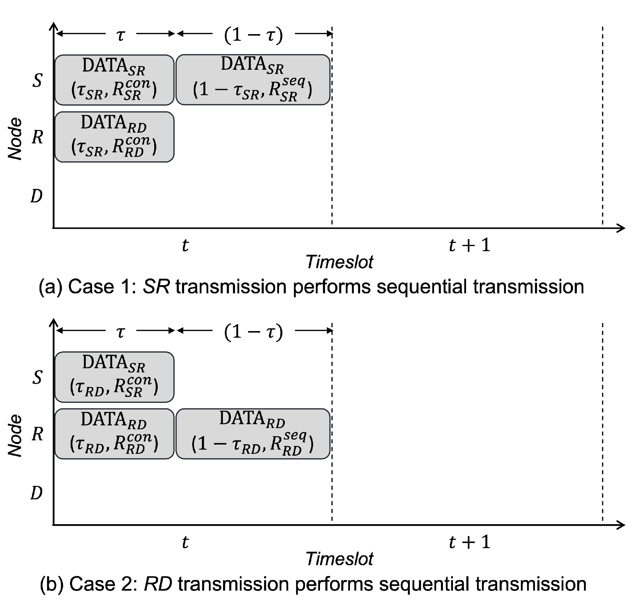
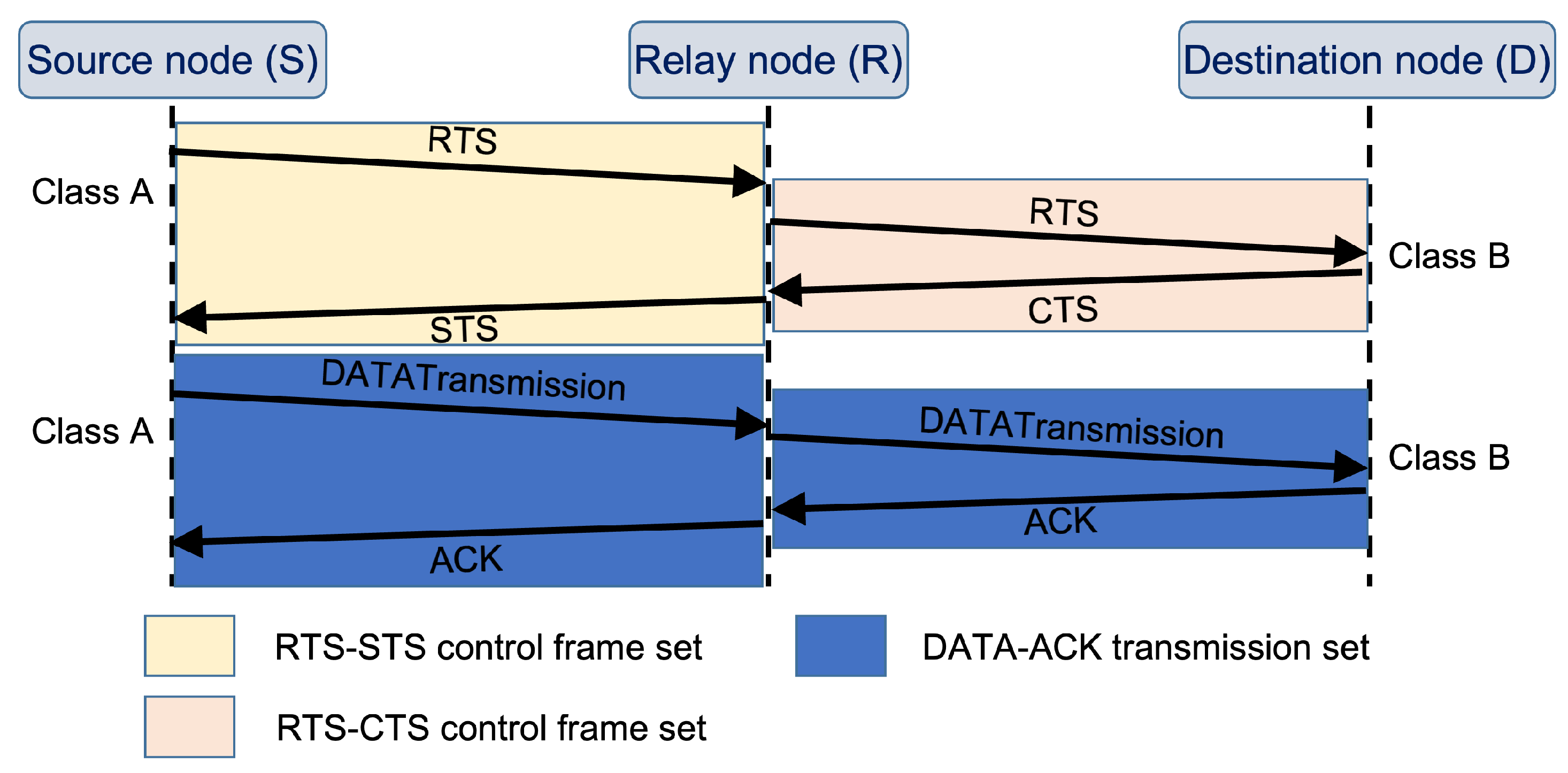
4. MCST Scheme
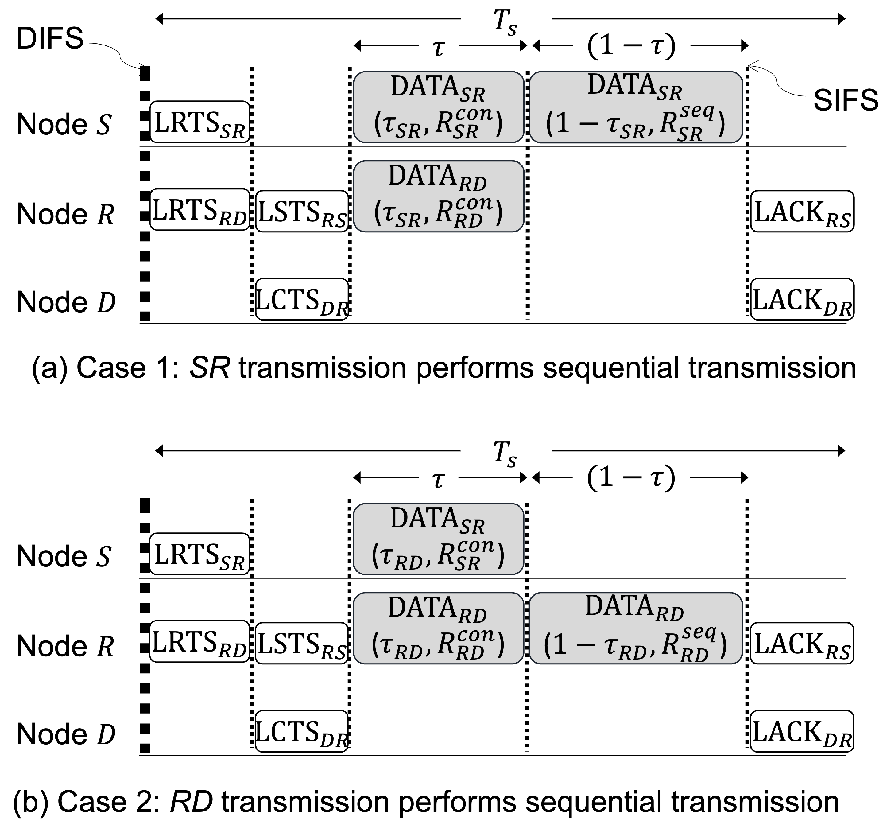
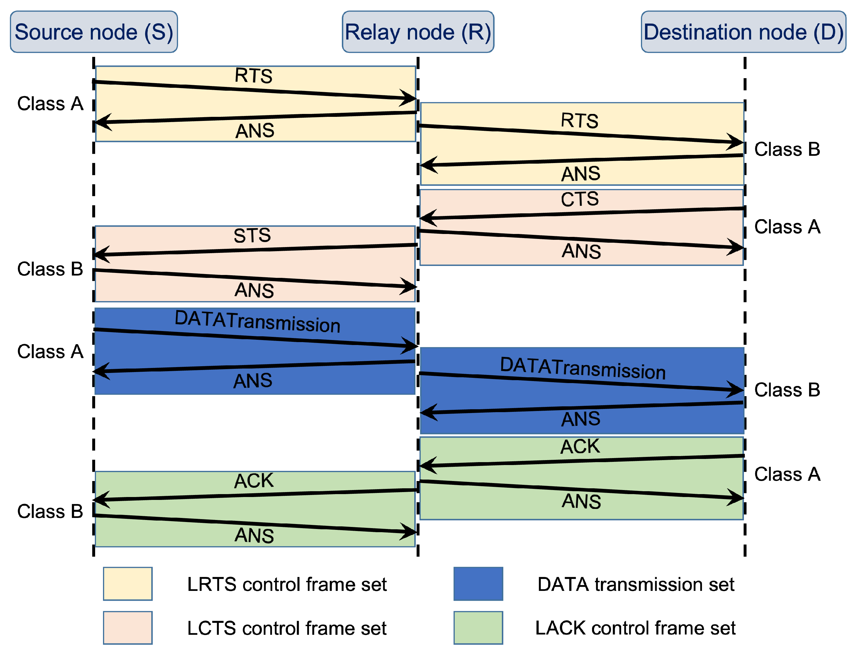
5. MCST Scheme over LoRa Network
6. Numerical Simulations
6.1. Simulation Scenarios and Settings
6.2. Simulation Results and Discussion
7. Conclusions
Author Contributions
Funding
Data Availability Statement
Acknowledgments
Conflicts of Interest
Abbreviations
| ACK | Acknowledgement |
| AI | Artificial Intelligence |
| ANS | Answer frame transmission |
| BRF | Basic relaying flow transmission |
| CSMA | Carrier sense multiple access |
| CSMA/LoRa | Carrier sense multiple access over LoRa network |
| CT | Concurrent transmission scheme |
| CTS | Clear-to-send |
| DCF | Distributed coordination function |
| FD | Full-duplex |
| FD-MCST | FD MAC protocol with MCST scheme |
| FRM | frame |
| HD | Half-duplex |
| IoT | Internet of Things |
| IUI | Inter-user interference |
| LACK | LoRaWAN acknowledgement |
| LCTS | LoRaWAN clear-to-send |
| LoRa | Long-range low-power wireless communications |
| LoRaWAN | LoRa wide area network |
| LPWAN | Low-power wide-area network |
| LRTS | LoRaWAN request-to-send |
| LSTS | LoRaWAN set-to-send |
| MAC | Medium access control protocol |
| MCST | Mixture of concurrent and sequential transmission scheme |
| MCST/LoRa | Mixture of concurrent and sequential transmission scheme over LoRa network |
| mMCST/LoRa | Modified MCST scheme over LoRa network |
| RTS | Request-to-send |
| RTS/CTS | Request-to-send/clear-to-send mechanism |
| SI | Self-interference |
| SIC | Self-interference cancellation |
| SINR | Signal-to-interference-plus-noise ratio |
| SNR | Signal-to-noise ratio |
| STS | Set-to-send |
| TDMA | Time-division multiple access |
| UAV | Unmanned aerial vehicle |
References
- Nakamura, T. 5G Evolution and 6G. In Proceedings of the 2020 IEEE Symposium on VLSI Technology, Honolulu, HI, USA, 16–19 June 2020; pp. 1–5. [Google Scholar] [CrossRef]
- Raza, U.; Kulkarni, P.; Sooriyabandara, M. Low Power Wide Area Networks: An Overview. IEEE Commun. Surv. Tut. 2017, 19, 855–873. [Google Scholar] [CrossRef]
- Kantelis, K.F.; Beletsioti, G.A.; Valkanis, A.; Nicopolitidis, P.; Papadimitriou, G.I. A TDMA-Based Access Protocol for Dense Networks with Moving Nodes for IoT Applications. Electronics 2023, 12, 1628. [Google Scholar] [CrossRef]
- Ghazali, M.H.M.; Teoh, K.; Rahiman, W. A Systematic Review of Real-Time Deployments of UAV-Based LoRa Communication Network. IEEE Access 2021, 9, 124817–124830. [Google Scholar] [CrossRef]
- Shi, W.; Zhou, H.; Li, J.; Xu, W.; Zhang, N.; Shen, X. Drone Assisted Vehicular Networks: Architecture, Challenges and Opportunities. IEEE Netw. 2018, 32, 130–137. [Google Scholar] [CrossRef]
- Pang, X.; Sheng, M.; Zhao, N.; Tang, J.; Niyato, D.; Wong, K.K. When UAV Meets IRS: Expanding Air-Ground Networks via Passive Reflection. IEEE Wireless Commun. 2021, 28, 164–170. [Google Scholar] [CrossRef]
- Shan, L.; Li, H.B.; Miura, R.; Matsuda, T.; Matsumura, T. A Novel Collision Avoidance Strategy with D2D Communications for UAV Systems. Drones 2023, 7, 283. [Google Scholar] [CrossRef]
- Shan, L.; Miura, R.; Kagawa, T.; Ono, F.; Li, H.B.; Kojima, F. Machine learning-based field data analysis and modeling for drone communications. IEEE Access 2019, 7, 79127–79135. [Google Scholar] [CrossRef]
- Dong, C.; Shen, Y.; Qu, Y.; Wang, K.; Zheng, J.; Wu, Q.; Wu, F. UAVs as an Intelligent Service: Boosting Edge Intelligence for Air-Ground Integrated Networks. IEEE Netw. 2021, 35, 167–175. [Google Scholar] [CrossRef]
- Davoli, L.; Pagliari, E.; Ferrari, G. Hybrid LoRa-IEEE 802.11 s opportunistic mesh networking for flexible UAV swarming. Drones 2021, 5, 26. [Google Scholar] [CrossRef]
- Saraereh, O.A.; Alsaraira, A.; Khan, I.; Uthansakul, P. Performance evaluation of UAV-enabled LoRa networks for disaster management applications. Sensors 2020, 20, 2396. [Google Scholar] [CrossRef] [PubMed]
- Liu, M.; Gui, G.; Zhao, N.; Sun, J.; Gacanin, H.; Sari, H. UAV-Aided Air-to-Ground Cooperative Nonorthogonal Multiple Access. IEEE Internet Things J. 2020, 7, 2704–2715. [Google Scholar] [CrossRef]
- Xiong, R.; Liang, C.; Zhang, H.; Xu, X.; Luo, J. FlyingLoRa: Towards energy efficient data collection in UAV-assisted LoRa networks. Comput. Netw. 2023, 220, 109511–109523. [Google Scholar] [CrossRef]
- Adelantado, F.; Vilajosana, X.; Tuset-Peiro, P.; Martinez, B.; Melia-Segui, J.; Watteyne, T. Understanding the Limits of LoRaWAN. IEEE Commun. Mag. 2017, 55, 34–40. [Google Scholar] [CrossRef]
- Shanmuga Sundaram, J.P.; Du, W.; Zhao, Z. A Survey on LoRa Networking: Research Problems, Current Solutions, and Open Issues. IEEE Commun. Surv. Tut. 2020, 22, 371–388. [Google Scholar] [CrossRef]
- Pham, C.; Ehsan, M. Dense deployment of LoRa networks: Expectations and limits of channel activity detection and capture effect for radio channel access. Sensors 2021, 21, 825. [Google Scholar] [CrossRef] [PubMed]
- Polonelli, T.; Brunelli, D.; Marzocchi, A.; Benini, L. Slotted ALOHA on LoRaWAN-design, analysis, and deployment. Sensors 2019, 19, 838. [Google Scholar] [CrossRef] [PubMed]
- Ahsan, S.; Hassan, S.A.; Adeel, A.; Qureshi, H.K. Improving channel utilization of LoRaWAN by using novel channel access mechanism. In Proceedings of the 15th International Wireless Communications & Mobile Computing Conference(IWCMC), Tangier, Morocco, 24–28 June 2019; pp. 1656–1661. [Google Scholar] [CrossRef]
- Okennedy, M.; Niesler, T.; Wolhuter, R.; Mitton, N. Practical evaluation of carrier sensing for a LoRa wildlife monitoring network. In Proceedings of the 2020 IFIP Networking Conference (Networking), Paris, France, 22–26 June 2020; pp. 614–618. [Google Scholar]
- Gamage, A.; Liando, J.C.; Gu, C.; Tan, R.; Li, M. LMAC: Efficient carrier-sense multiple access for LoRa. In Proceedings of the 26th Annual International Conference on Mobile Computing and Networking, London, UK, 21–25 September 2020; pp. 1–13. [Google Scholar] [CrossRef]
- Farooq, M.O.; Pesch, D. A search into a suitable channel access control protocol for LoRa-based networks. In Proceedings of the 43rd Conference on Local Computer Networks (LCN), Chicago, IL, USA, 1–4 October 2018; pp. 283–286. [Google Scholar] [CrossRef]
- Bouguera, T.; Diouris, J.F.; Chaillout, J.J.; Jaouadi, R.; Andrieux, G. Energy consumption model for sensor nodes based on LoRa and LoRaWAN. Sensors 2018, 18, 2104. [Google Scholar] [CrossRef] [PubMed]
- Khun, A.T.P.; Shan, L.; Lim, Y.; Tan, Y. Study of Network Capacity for Mixture of Concurrent and Sequential Transmission Scheme over LoRa Networks. IEICE Tech. Rep. 2023, 122, 175–180. [Google Scholar]
- Augustin, A.; Yi, J.; Clausen, T.; Townsley, W.M. A study of LoRa: Long range & low power networks for the Internet of Things. Sensors 2016, 16, 1466. [Google Scholar] [CrossRef] [PubMed]
- International Telecommunications Union. Propagation Data and Prediction Models for the Planning Of Short-Range Outdoor Radio Communication Systems and Radio Local Area Networks in the Frequency Range 300 MHz to 100 GHz; Recommendation ITU-R P.1411-11; International Telecommunications Union: Geneva, Switzerland, 2021; pp. 1–56. [Google Scholar]
- Khun, A.T.P.; Lim, Y.; Tan, Y. FD-MCST design and analysis for multihop wireless networks. Ad Hoc Netw. 2022, 136, 102977–102991. [Google Scholar] [CrossRef]
- LoRa Alliance Technical Committee. LoRaWAN 1.1 Specification; LoRa Alliance: Beaverton, OR, USA, 2017; pp. 1–101. [Google Scholar]


| Parameter | Value |
|---|---|
| Network coverage size | 1 km × 1 km × 150 m |
| Transmit power (P) | 20 mW |
| Frequency () | 920 MHz [8] |
| Channel bandwidth (B) | 400 kHz [8] |
| Attenuation constant () | 2.34 [8] |
| Shadowing parameter () | 5.06 dB [25] |
| RSSI, Basic rate () | −98 dBm, 200 kbps |
| −117 dBm, 20 kbps [8] | |
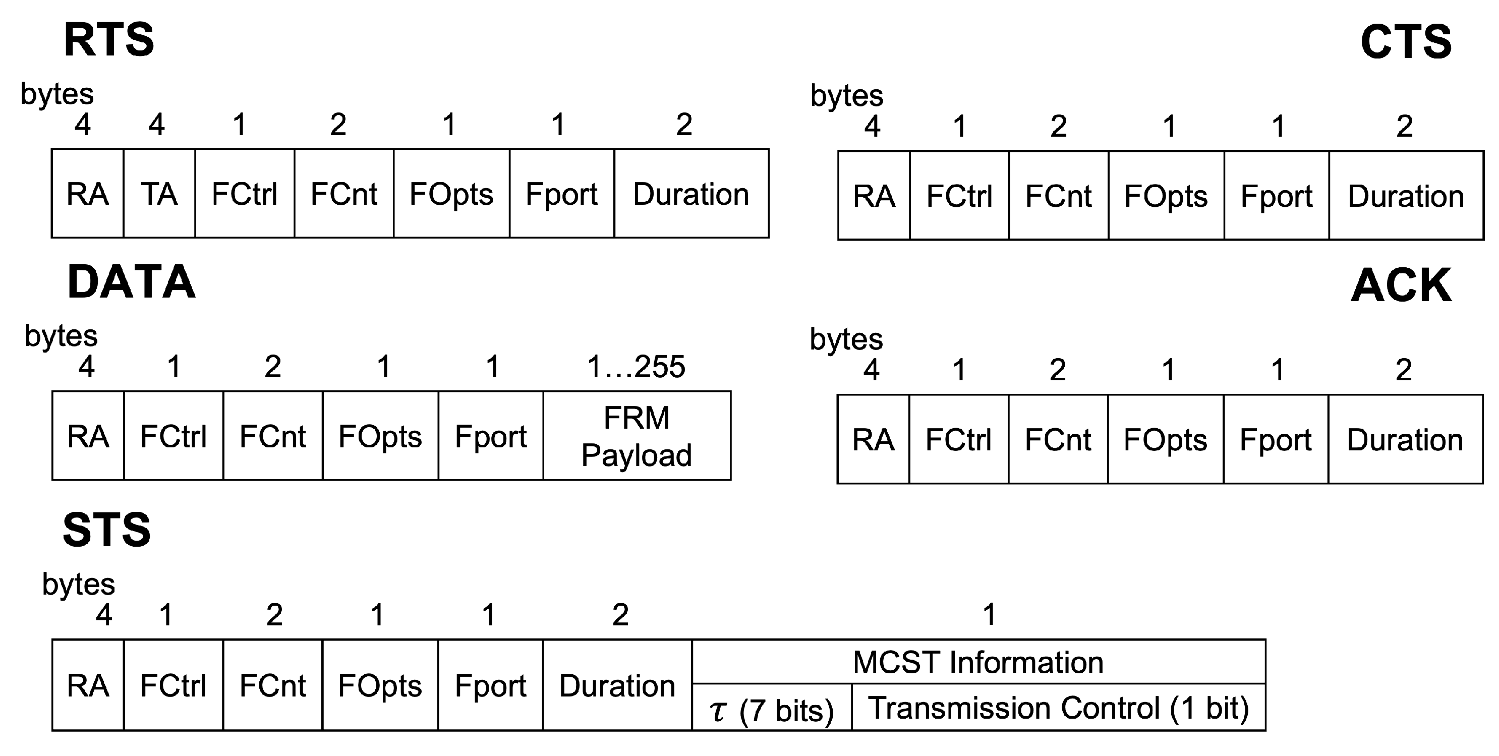
| RTS size | 120 bits |
| CTS size | 88 bits |
| STS size | 96 bits |
| ACK size | 88 bits |
| Preamble time | 401.41 ms |
| Number of simulations | 10,000 times |
| Achievable BRF Throughput [kbps] | Achievable Transmission Latency [s] | Achievable Energy Consumption [mJ] | |
|---|---|---|---|
| CSMA/LoRa | 4.79 | 0.418 | 8.36 |
| MCST/LoRa | 4.89 | 0.409 | 8.17 |
| mMCST/LoRa | 4.92 | 0.407 | 8.13 |
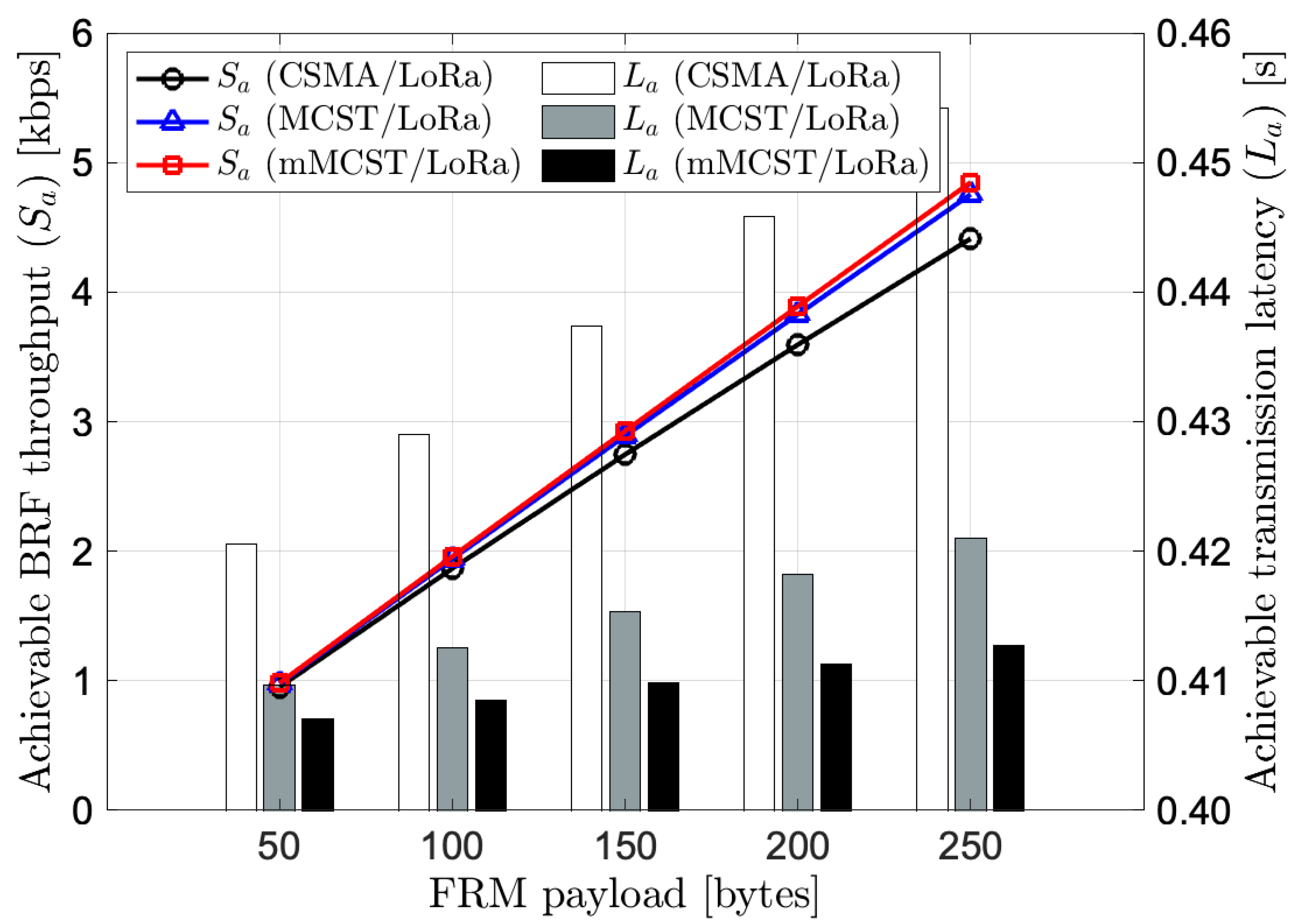
| FRM Payload [Bytes] | |||||
|---|---|---|---|---|---|
| 50 | 100 | 150 | 200 | 250 | |
| CSMA/LoRa | 8.41 | 8.58 | 8.75 | 8.92 | 9.09 |
| MCST/LoRa | 8.19 | 8.25 | 8.31 | 8.36 | 8.42 |
| mMCST/LoRa | 8.14 | 8.17 | 8.20 | 8.23 | 8.25 |
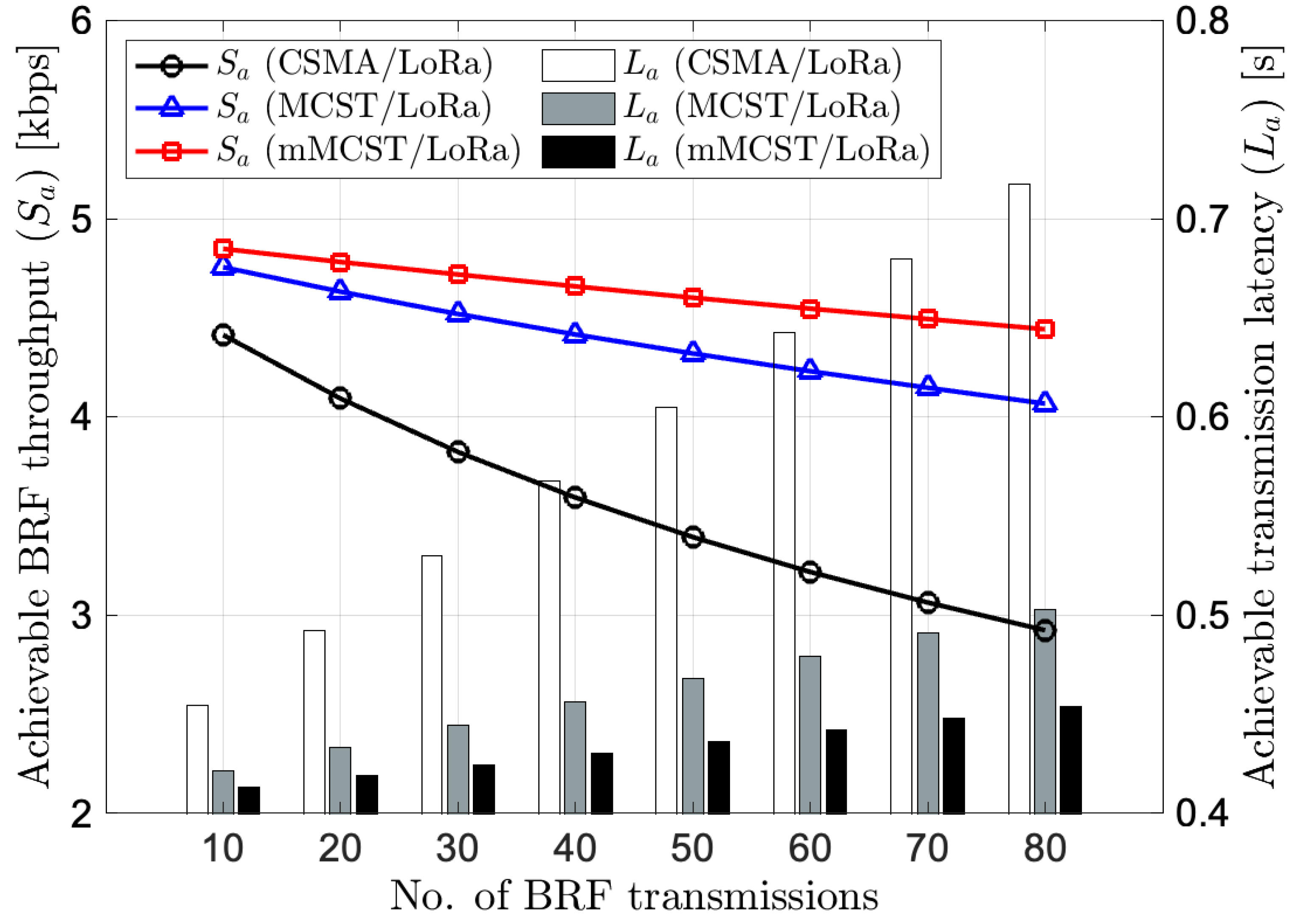
| No. of BRF Transmissions | ||||||||
|---|---|---|---|---|---|---|---|---|
| 10 | 20 | 30 | 40 | 50 | 60 | 70 | 80 | |
| CSMA/LoRa | 9.09 | 9.84 | 10.59 | 11.35 | 12.10 | 12.85 | 13.59 | 14.35 |
| MCST/LoRa | 8.42 | 8.66 | 8.89 | 9.12 | 9.35 | 9.59 | 9.81 | 10.05 |
| mMCST/LoRa | 8.25 | 8.37 | 8.49 | 8.61 | 8.72 | 8.84 | 8.95 | 9.07 |
Disclaimer/Publisher’s Note: The statements, opinions and data contained in all publications are solely those of the individual author(s) and contributor(s) and not of MDPI and/or the editor(s). MDPI and/or the editor(s) disclaim responsibility for any injury to people or property resulting from any ideas, methods, instructions or products referred to in the content. |
© 2023 by the authors. Licensee MDPI, Basel, Switzerland. This article is an open access article distributed under the terms and conditions of the Creative Commons Attribution (CC BY) license (https://creativecommons.org/licenses/by/4.0/).
Share and Cite
Khun, A.T.P.; Shan, L.; Lim, Y.; Tan, Y. MCST Scheme for UAV Systems over LoRa Networks. Drones 2023, 7, 371. https://doi.org/10.3390/drones7060371
Khun ATP, Shan L, Lim Y, Tan Y. MCST Scheme for UAV Systems over LoRa Networks. Drones. 2023; 7(6):371. https://doi.org/10.3390/drones7060371
Chicago/Turabian StyleKhun, Aung Thura Phyo, Lin Shan, Yuto Lim, and Yasuo Tan. 2023. "MCST Scheme for UAV Systems over LoRa Networks" Drones 7, no. 6: 371. https://doi.org/10.3390/drones7060371
APA StyleKhun, A. T. P., Shan, L., Lim, Y., & Tan, Y. (2023). MCST Scheme for UAV Systems over LoRa Networks. Drones, 7(6), 371. https://doi.org/10.3390/drones7060371