Article

Drone High-Rise Aerial Delivery with Vertical Grid Screening

1
School of Engineering, Faculty of Science and Engineering, Macquarie University, Sydney, NSW 2109, Australia
2
School of Computing, Faculty of Science and Engineering, Macquarie University, Sydney, NSW 2109, Australia
*
Author to whom correspondence should be addressed.
Drones 2023, 7(5), 300; https://doi.org/10.3390/drones7050300
Submission received: 14 April 2023 / Revised: 29 April 2023 / Accepted: 2 May 2023 / Published: 4 May 2023
(This article belongs to the Special Issue Drones: Opportunities and Challenges)

Abstract

:
Delivery drones typically perform delivery by suspending the parcel vertically or landing the drone to drop off the package. However, because of the constrained landing area and the requirement for precise navigation, delivering items to customers who reside in multi-story apartment complexes poses a unique challenge. This research paper proposes a novel drone delivery system for multi-story apartment buildings with balconies that employ two methods for Vertical Grid Screening (VGS), i.e., Grid Screening (GS) and Square Screening (SS), to detect unique markers to identify the precise balcony that needs to receive the product. The developed drone has a frame size of 295 mm and is equipped with a stereo camera and a ranging sensor. The research paper also explores the scanning and trajectory methods required for autonomous flight to accurately approach the marker location. The proposed machine learning system is trained on a YOLOv5 model for image recognition of the marker, and four different models and batch sizes are compared. The 32-batch size with a 960 × 1280 resolution model provides an average of 0.97 confidence for an extended range. This system is tested outdoors and shows an accuracy of 95% for a planned trajectory with 398 ms detection time as a solution for last-mile delivery in urban areas.

1. Introduction

Drone technology is becoming increasingly popular because of the rising demand for quick and effective delivery services in urban areas. A drone is a type of aircraft that is operated remotely, also known as an Unmanned Aerial Vehicle (UAV). The applications of drones were originally confined to military purposes, such as aerial warfare and surveillance. However, with growing modern technology, affordability, and industry 4.0, drones are being used in a multitude of other fields, including parcel delivery [1], wildlife conservation [2], agriculture [3], search and rescue [4], human action detection [5], and photography [6]. Transportation is one of the important aspects of active operations in last-mile delivery [7,8,9], emergency medical deliveries in rural communities [10], swarm logistics for military deliveries [11], and passenger transportation [12]. Thus, the applications of drone delivery are on the rise, and rapid research and development in this field have become critical.
Drone delivery applications in urban environments are expanding with growing e-commerce and online shopping markets. Companies like Amazon Prime Air, Wing, DHL Parcelcopter, FedEx, Zipline, and Matternet are among the many companies at the forefront of drone delivery. All such companies employ deliveries typically in rural and regional areas with no high-rise buildings or large populations. However, drone deliveries of parcels in dense urban areas present both major new challenges and key opportunities. Recent studies and trends have shown that a growing number of the population will be residing in apartments and condominiums in the future [13]. Currently, most of the parcels delivered in urban areas and cities use ground vehicles with human drivers. According to a study in the United States, a driver typically spends about 9 min on average to find a parking space before dropping off a parcel [8]. Hence, ideas related to last-mile delivery, specifically in apartments with balconies, have a high demand and potential to avoid traffic congestion, lower air pollution, save time, and lower the delivery cost. According to a report submitted in 2018 by AlphaBeta on drone deliveries in ACT (Australian Capital Territory), drone deliveries will reduce traffic congestion by replacing 35 million vehicle km/ year reducing 8000 tons of CO2 emissions each year [14].
The current literature related to last-mile delivery using drones is analysed based on factors such as different positioning techniques, delivery locations in urban areas, and consideration of weather conditions. DroneTalk [15] is at an early prototype stage with very limited tests performed in urban spaces with marker detection for identifying accurate parcel delivery locations. Further, most drone delivery systems rely heavily only on GPS positioning to navigate to the desired location [16,17,18,19]. Very few last-mile delivery systems, such as the Flytrex drone delivery system [19] and DroneTalk [15], take weather conditions into account. The Flytrex technology only checks the weather before takeoff. However, it cannot deal with scenarios where the weather suddenly gets worse (such as an unexpectedly high wind). One of the most researched and practical ideas for drone delivery is using the truck and drone approach in last-mile deliveries [20]. The authors in [21] propose an efficient Truck Drone Routing Algorithm (TDRA) that can potentially reduce customer waiting time by 46.8% and reap more than 95% of the usage potential of UAVs for parcel delivery in certain zones. The analysis performed in [22] suggests that the benefits of using drones are strongly affected by the accessibility to a customer compared to using a classical vehicle approach solely. The research in [23] formulates a mixed integer linear program (MILP) that shows the proposed formulation can be solved with up to 15 customers. Amazon proposed an interesting patent for drone deliveries in [24], where they suggest a multi-level fulfilment centre for take-off and landing in urban settings for highly dense areas.
Recent advances in machine learning, artificial intelligence, and microprocessors have enabled powerful computational capabilities for autonomous operations in many multidisciplinary research fields [25]. In a recently published article [26], the authors explore a resource allocation optimisation problem where a central authority chooses a small number of operators from a huge pool of candidates to carry out a task in the most efficient way possible. The study shows promising results on the performance and usability of computationally effective stochastic multistage optimisation algorithms for drones operating in the same framework as firefighters in a fire extinguishing mission. Remote operation of a drone can vary in levels of autonomy from semi-human assisted, which corresponds to some level of auto-pilot using the flight controller to act completely autonomously using onboard computing and sensors to remove the need for a human pilot [27]. Autonomous missions in UAVs consist mainly of three major components. The first one is ‘Guided’, where the drone calculates and follows a pre-set optimum route from a start location to an endpoint avoiding obstacles and restricted air spaces. The second is ‘Navigation’, which involves calculating position, location, velocity, and other similar data values for a pre-defined navigation frame. Last is ‘Control’, which explains creating a real-time control command sequence that allows the drone to follow along the optimal route. The authors in [28] present a detailed design and implementation of a fixed-time stability control algorithm for aerial formation control of networked quadrotors. The algorithm is distributed in nature and employs a leader–follower scheme along with a new Homogeneous Nonsingular Terminal Sliding Function to guarantee global asymptotic stability. The study uses similar hardware and software tools as our research (NVIDIA Jetson Nano with Ubuntu Bionic 18.04, Pixhawk, and ROS Melodic) to perform various simulation and outdoor field tests.
Drone deliveries present unique challenges when the deliveries are in high-rise apartments or building structures with balconies. The concept is new, and there is very limited research in the area due to government rules and regulations [29] and public attitude towards such technology [30]. Only a minority of drone delivery systems [9,15,31] focus on delivering parcels to multi-story apartment buildings, mostly concept-based work. Researchers have analysed different drone delivery locations in urban areas based on outdoor open spaces [17], centralised drop-off locations near customers’ homes [16,18], and community couriers [32], roofs of buildings [19], balconies or porches [9], and drop-off location inside a building [15]. Autonomous navigation of drones requires accurate GPS positioning and terrain information for path planning. Researchers from ETH Zurich [9] suggest a novel drone delivery approach to a balcony using a visual marker (WhyCon). The concept is at an early development stage where the drone moves to the GPS location, approaches the marker in a straight line, and descends on detection. However, the drone requires the target GPS location to be very accurate and the ability to scan entire buildings. In a similar approach, the authors in [33] present drone delivery using deep learning around a door or yard of a house. Tested mainly in a simulation environment, drones employing the suggested system located and arrived at the front doors of the 20 test residences 161% faster than drones utilising a frontier exploration-based strategy. Compared to [9], our work addresses the scanning issue of an entire building to locate the correct marker upon arriving at the target GPS location. Additionally, in contrast to [33], our work involves field testing of drone delivery in real-world conditions.
This research aims to optimise drone delivery using vertical grid screening for apartments with balconies. The following points describe the contributions of this paper. (i) We describe a novel method called vertical grid screening, that utilises the camera’s FOV (Field of View) to form grids over the desired location to be scanned (in this instance, the apartments). The grid-based screening aims to aid the time of detection for the drone. (ii) The proposed system shows an architecture for the vertical detection of markers for apartment deliveries. (iii) The system compares and integrates the YOLO (You Look Only Once) model that offers high accuracy with the lowest detection time. (iv) Our proposed method is tested for apartment delivery as well as user authentication with the trained YOLO model and custom application using the selected trajectory.
The rest of the paper is organised as follows. Section 2 describes the system design and architecture and provides an overview of the proposed system goals. The overall system end-to-end Drone Vertical Delivery System algorithm is defined in Section 3. In Section 4, the hardware and software used are explained in detail. Section 5 discusses the marker detection method and analyses the different model performances. Section 6 shows the experimental results for the drone’s scanning algorithm in outdoor environments. The conclusions and future work are discussed in Section 7.

2. System Design and Architecture

2.1. System Goals, Challenges, and Model Assumptions

Our overall goal is to support efficient cost-effective drone-based delivery of parcels to apartment balconies in high-rise buildings. Figure 1a illustrates example photographs of typical apartment balcony sizes [34], and Figure 1b shows example photographs of different apartments in Australia [35]. There are no standard measurements or structures for apartments with balconies as observed below; this poses unique challenges to the existing drone delivery system.
Given a delivery address, including the street address as well as the floor and apartment unit number, e.g., apartment 807, the drone still faces the dilemma of finding which of the floors corresponds to the correct floor as well as the correct apartment balcony on that floor for delivery. Since apartment floor numbering conventions can vary in arbitrary ways and builders can skip the numbering of floors for a variety of reasons, the drone cannot rely simply on counting the floors from the bottom. Moreover, once on a given floor, the drone must search the balconies on that floor to find the correct address, circumnavigating the building.
Our system model makes several assumptions. We assume that each delivery recipient has a way to mark or identify their address to the drones distinctly from other addresses in the same apartment building. A convenient solution is for each recipient to deploy a visible marker from their balcony. In a practical implementation, the users who will employ the drone delivery service must be trained to check the marker’s print quality and placement of the marker to avoid any human errors during apartment detection. While it is also possible to consider more general, marker-less solutions where an AI-equipped drone reasons about which balcony is the correct one without any marker aid from the recipient, this adds a layer of identification and authentication complexity beyond the scope of this paper. Hence, we assume that there will be multiple such markers visibly deployed on the balconies of the apartment building by its residents, where each marker is distinctly identifiable from the others. We also assume the typical quad/hex copter drone has sufficient resources such as cameras and other sensors and computational abilities to perform onboard real-time vision recognition. The implementation of the sensor fusion model is intensive and power-consuming. To avoid any safety risks, the execution of these models promptly and with the lowest possible power consumption is imperative for the drone system.
Our challenges are therefore to design and validate a suitable process that efficiently searches vertically for the proper marker given a delivery address and to design and verify the marker recognition algorithm itself.

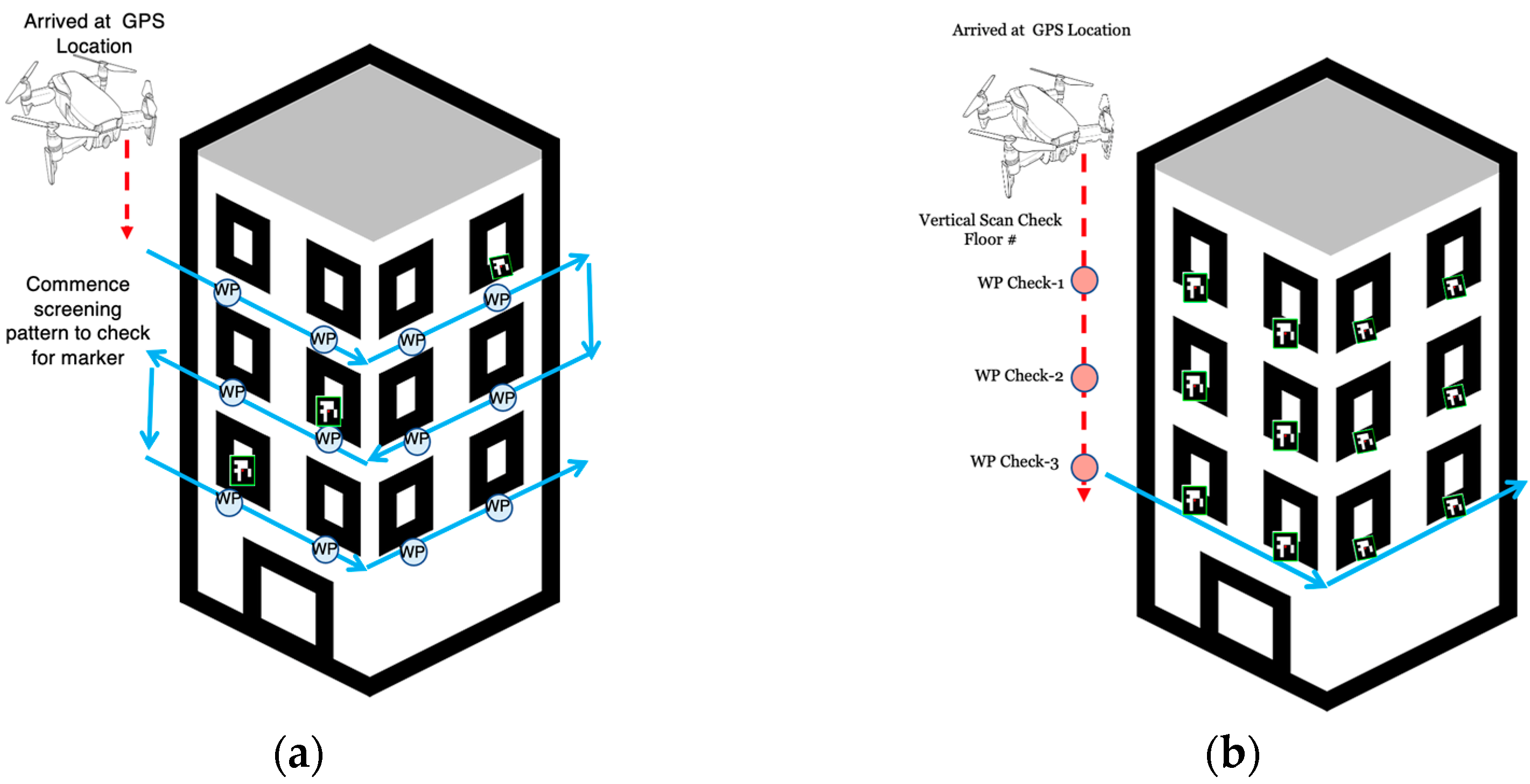
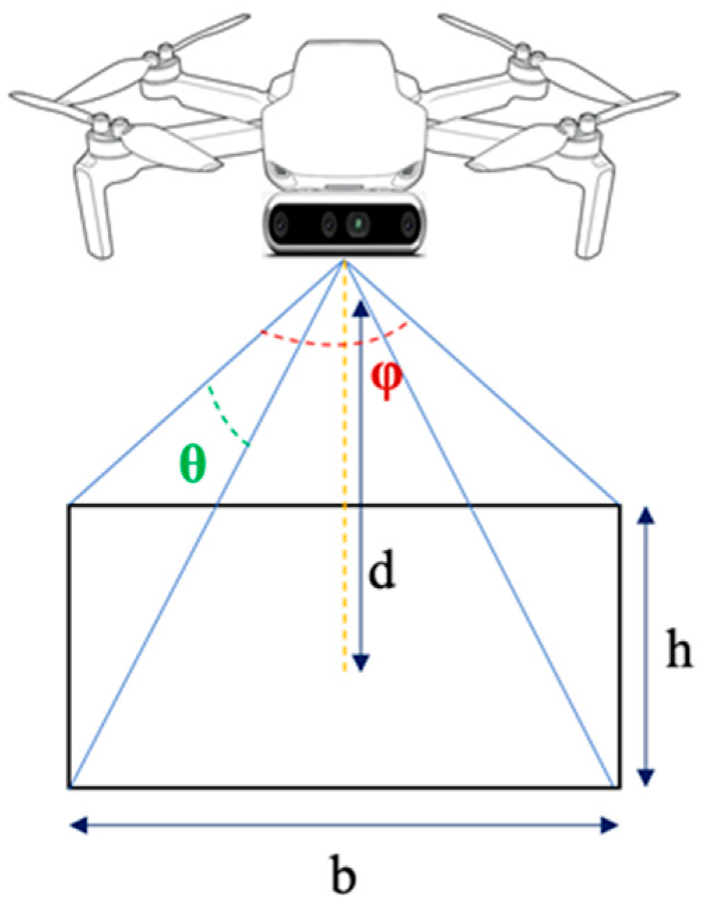
2.2. Vertical Grid Screening

The drone scanning and trajectory control algorithm is a crucial step in determining the drone’s final delivery process [36]. According to [37], the suggested method of using the modified genetic algorithm (GA) and A* algorithm to enable various constraints of optimal trajectory design shows potential. All alternatives produced by the trajectory planning algorithm satisfy all fundamental criteria, including the UAV’s correction and turning radius. The research work in [38] describes the development of a full flight planner for quadrotor UAVs that produces a coverage trajectory with the shortest possible completion time. According to experimental findings, the trajectory offers a superior navigational solution for UAVs than the GPS coordinates offered by the current CPP (Coverage Path Planning) algorithms. The work in [37] significantly lacks realistic constraints which could potentially improve the algorithm optimisation model. Additionally, in [38], the authors propose a downward scanning approach. A new drone scanning and trajectory control algorithm is needed to solve this problem with an improvement in the scanning approach.
We propose an investigation of a novel Vertical Grid Screening (VGS) method that allows scanning of the delivery apartment building while providing maximum coverage for the camera FoV. There are two proposed patterns in the VGS method. (i) Grid Screening: The Grid Screening method shown in Figure 2a is used when the unique identification marker is only placed on apartments that subscribe to the drone delivery service. In such a case, the trajectory is pre-defined using the camera FoV as a reference. (ii) Square Screening: As Figure 2b shows, the Square Screening method is used when the unique marker is assumed to be on every apartment unit. In this case, the drone scans between each marker at every level to determine the correct floor number associated with the unit number. Once confirmed, it employs square screening to determine the apartment marker on the appropriate floor.

2.3. Marker Detection

For the marker detection algorithm, we propose an evaluation of two types of well-known vision algorithms for their practical efficacy in real world tests, namely OpenCV and YOLOv5. OpenCV is a standard vision library used in many applications, while YOLOv5 is a relatively new deep learning algorithm for general purpose object recognition. The YOLOv5 models train quickly which allows rapid development for the multiple variations in batch sizes. Apart from this, the model has an intuitive data file system structure and inference ports that work with images or video feeds.
For the marker type, we propose an evaluation using ArUco markers for detection. Various types of markers are used in many robotics applications where vision-based sensors are installed [39,40]. These sensors are used by the robot camera for visual recognition and usually assist in landing, warehouses, or locating specific objects more accurately once the drone reaches its set GPS coordinates. Authors in [41] use the ArUco marker detection among other sensors to improve the landing precision of a delivery drone. The presented system relies on GPS and requires obstacle-free situations. The authors in [42] present an efficient technique of ArUco marker detection and recognition using neural networks, with the camera on the UAV. By altering the regression process, it forecasts the locations of the four corners. According to research observations, the suggested novel technique was successful through both integral and independent classes in detecting and identifying ArUco markers with high mAP and F1 scores > 0.9.

3. End-to-End Drone Vertical Delivery System

This section elaborates on the system algorithm used for drone delivery. First, the flow chart diagram of the overall algorithm is explained in detail which is uploaded to the computing board’s software as a package. Next, a method that implements IoT authentication is explained.

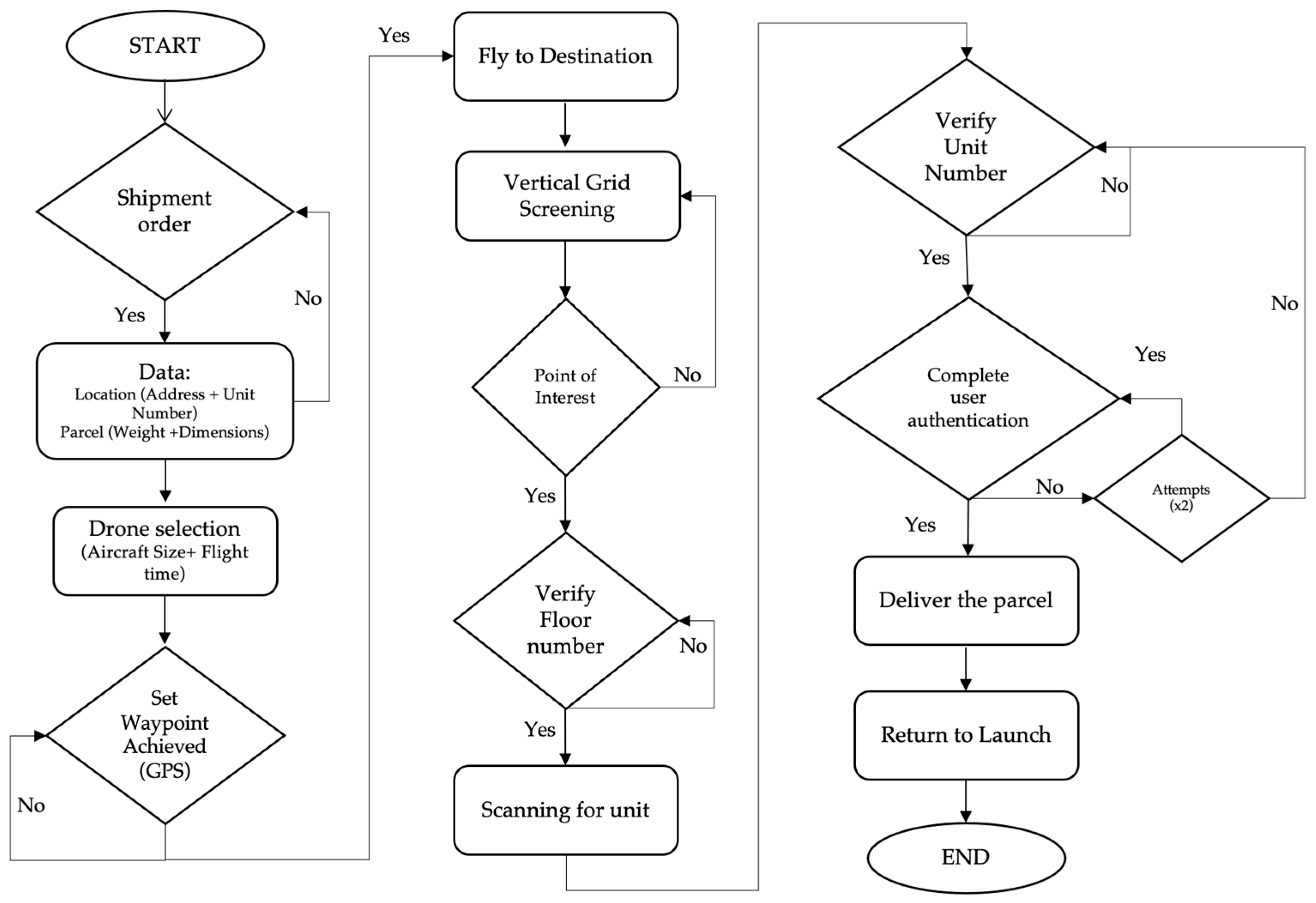
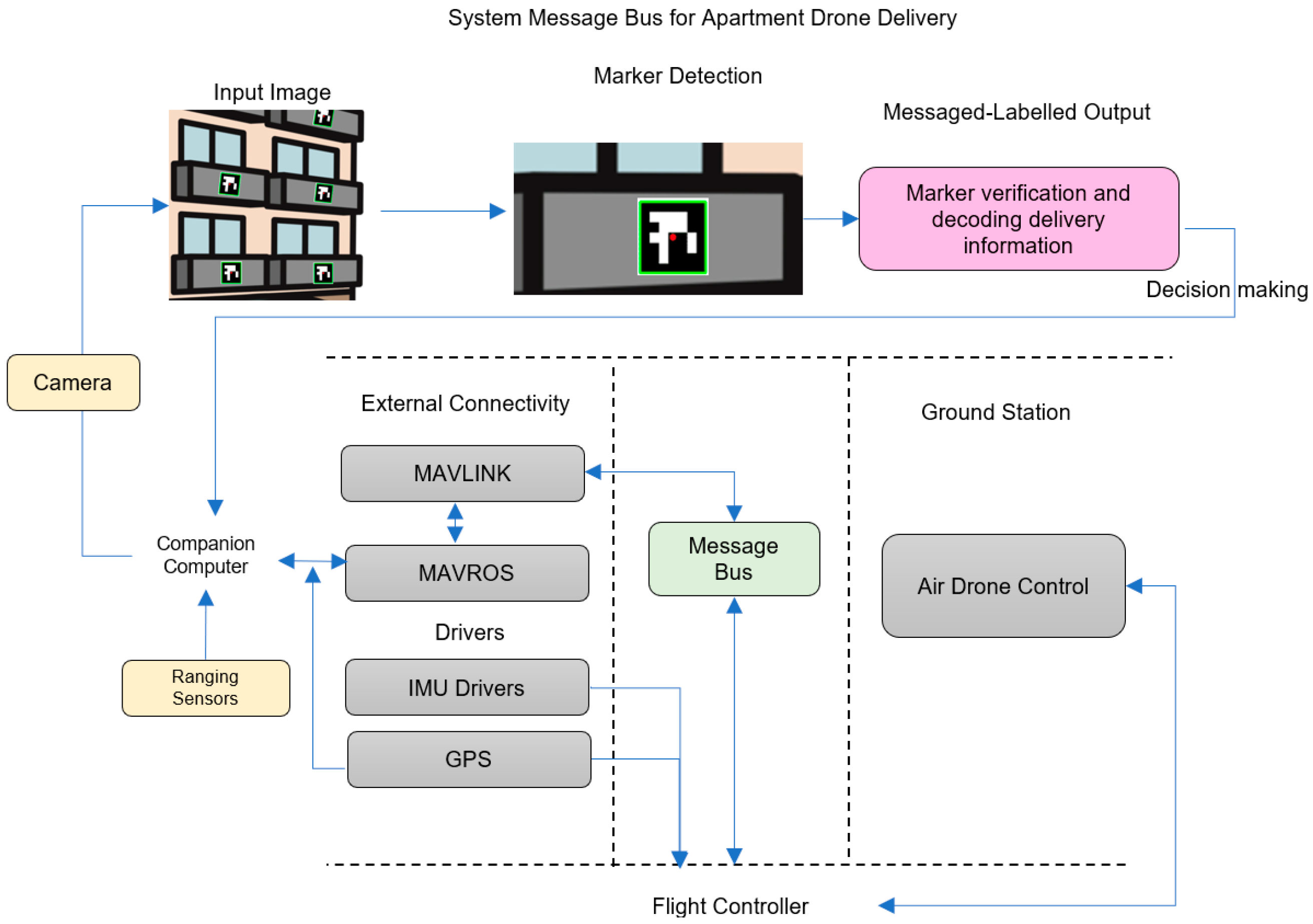
3.1. Block Diagram of the Delivery System
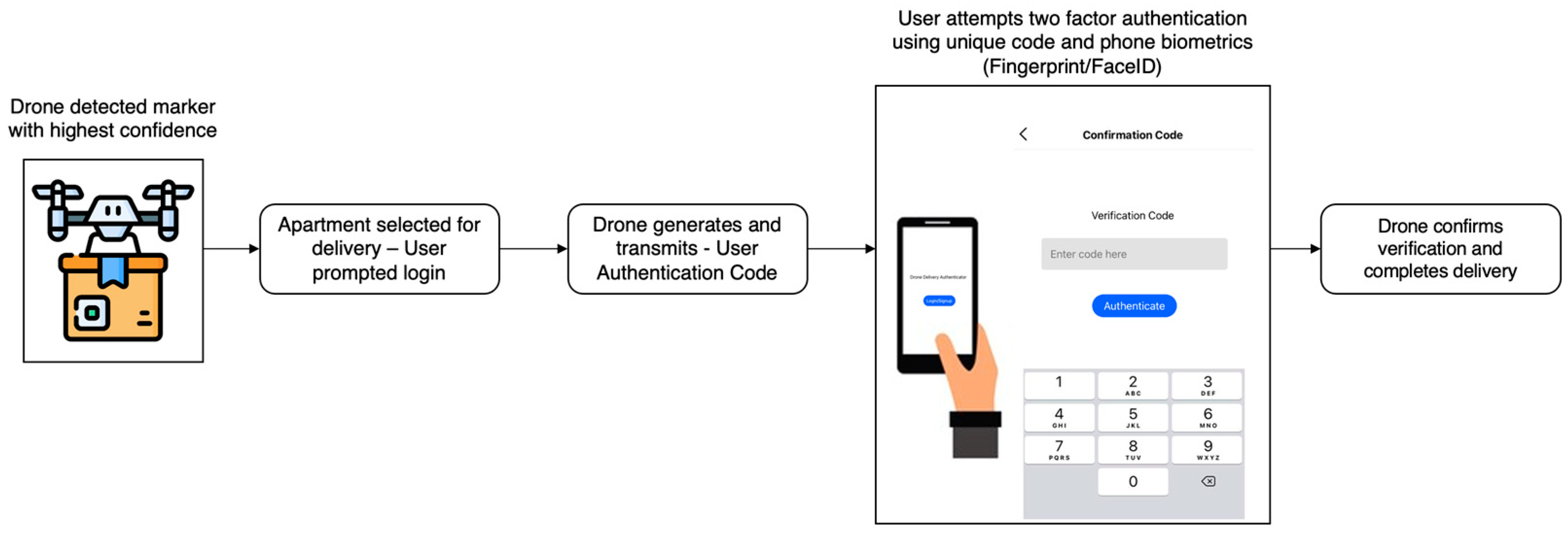
The flowchart of the proposed drone delivery for apartments with balconies is shown in Figure 3. The algorithm code is written in Python language and uploaded in the ROS Noetic (Robot Operating System) package that communicates with the flight controller (FC). The procedure starts when a shipment order is received with the location coordinates and unit number. Depending on the parcel weight and dimensions, the appropriately sized drone is selected. The flight time is calculated, and the path planning procedure is uploaded to the drone’s control software. If the GPS waypoint is not accurately loaded or the flight time required exceeds the drone’s capacity, the request is made again until resolved. Once the GPS waypoints are set, the drone flies to the destination coordinates.
Upon arriving at the GPS location, the drone starts hovering at the set altitude and performs the Vertical Grid Screening (VGS) method. If it detects the point of interest, it moves to verify the floor number. If verified correctly, it scans for the unit and unit number which is present on the marker.
Once verified correctly, the IoT authentication procedure is set into motion. The drone attempts to authenticate the user twice. If no authentication is received, the drone re-attempts to verify the unit number. If the authentication succeeds, the drone moves towards the marker located on the balcony and delivers the parcel. After this, the drone returns to the launch position.

3.2. Verification

Deliveries that were stolen have grown more frequent in modern times, with reports of people pretending to be recipients or stealing packages from drop-off locations becoming regular. Hence, while the drone is delivering the parcel to the correct apartment number, it follows an IoT-based user authentication procedure as shown in Figure 4.
Upon detection of the unique marker with the highest confidence, the customer is prompted and sent a login link. The marker contains information about the floor level and apartment number. There is no information about the person living in that apartment. A two-factor privacy setup will have a unique ID associated with the marker that could match the ID information given to the drone. A drone that does not belong to the delivery service will not receive any information about the apartment. The system may also be further enhanced with protection pairing between the drone and the apartment marker using this proposed framework [43]. This message also contains the User Authentication Code generated by the drone and transmitted. The user attempts a two-factor authentication which first requests the initial sign-in to the application and then prompts the user to input the authentication code. Once the drone confirms this verification, it moves towards the designated spot and completes the delivery.
The assumptions are that the position of the marker is at the center of the balcony and that the user is available at the time of delivery. The drone will use visual odometry as proposed by [9], and the drone will estimate the width and height of the given balcony. Upon estimation, the drone will continue the package delivery process using either of the proposed solutions. (a) Origami Drone: The package’s recipient can hold the drone, as seen in [44], which allows the person to collect the package safely. In this case, the drone will not require a landing space; once inside the balcony, the user may hold the drone by its cage and remove the package. (b) Parcel Suspension: The drone will use the onboard ranging sensor to estimate a flat surface and suspend the parcel. Once it reaches the surface, the user will detach the parcel.

4. Drone Vertical Delivery System Implementation

This section discusses hardware and software components and subsystems needed to implement the drone vertical delivery system, including onboard computer used for the autonomous control of the drone and the system communication between the computing board and the flight controller.

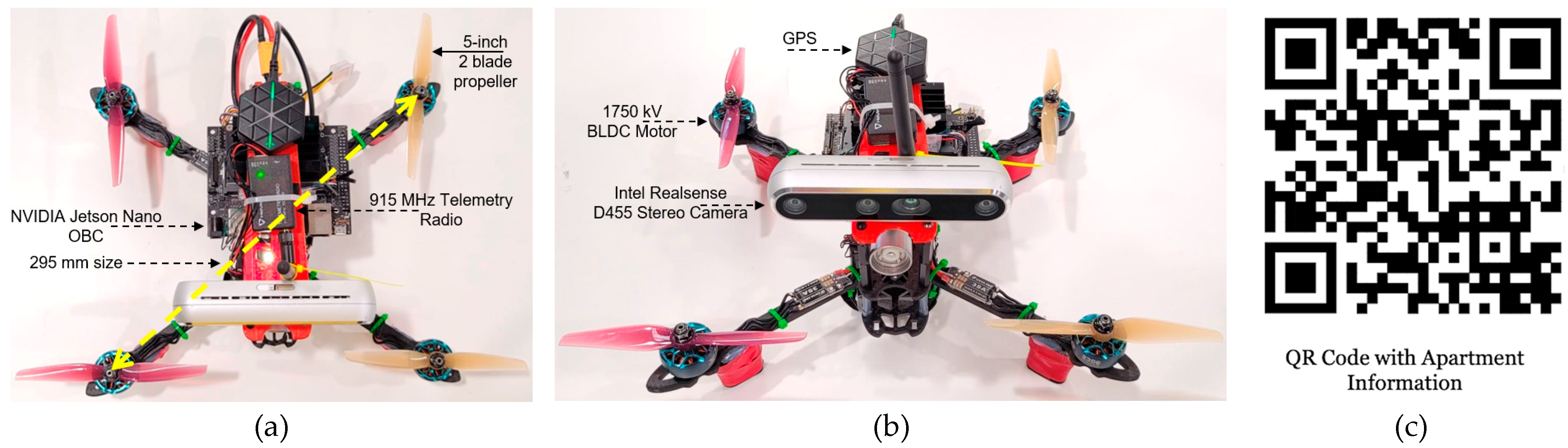
4.1. Drone Specifications

Our model of the drone used for validation and testing has a frame size of 295 mm. Figure 5a,b show the photograph of the drone used for testing, and Figure 5c shows the QR code with the apartment information. The propellers used are two blades and are 5 inches in length with four 1750 Kv motors (Kv: constant velocity of the Brushless DC motor). The 3S 3200 mAh LiPo battery has a capacity for a 20–25 min flight time with a maximum load of 1.2 kg. The forward-facing camera used is an Intel stereoscopic depth camera. The system is also equipped with a LiDAR for range measurement between the drone and the apartment. The drone’s flight path and verification are controlled by the onboard computer (OBC) that has a quad-core ARM Cortex-A57 MP Core processor. The OBC requires a supply of 5 V and 3 A to operate. The flight controller is encoded with the latest Ardupilot software to operate desired flight modes and motor control. The appendix includes an additional Table A1 with detailed specifications of the drone system.

4.2. Types of Onboard Computer

There is a lot of incentive in designing flight avionics using open-source hardware that is easy to customise and configure. Designing a drone from scratch is very useful for research designing for specific applications. There are many options when selecting the onboard computers, flight controllers, and sensors for the drone [45,46]. Most popular flight controllers include the Pixhawk series of flight controllers [47,48,49], Navio [50], and iNAV [51], to name a few. The onboard computers include the Raspberry Pi series [52] and the NVIDIA Jetson series [41] among the most popular.
The Pixhawk Flight Controller (FC) is an open-source board allowing developers to implement their programs to control the drones’ functions. The FC has in-built sensors such as GPS for location data (latitude and longitude), 9 DoF (Degree of Freedom) IMU (Inertial Measurement Unit) for orientation YPR (yaw pitch roll) data, and a Barometer for altitude sensing data. All these sensors together allow the drone’s FC software to send and receive commands that control the speed of the BLDC (Brushless Direct Current) motor. To allow the drone for advanced control operations, data processing, and path planning, a computing board is connected to the FC.
Various types of OBC hardware can be used to connect to the flight controller depending on the size, power requirements, and CPU/ GPU, among other features. The most popular ones are the Raspberry Pi 4B and the NVIDIA Jetson Nano. These two boards have comparable performance and vary depending on the application in use. The RPi 4B is less expensive than the Nano. It also comes with Wi-Fi and Bluetooth by default. The Table 1 gives a short comparison of these two OBCs
On the downside, even if the hardware is 64 bits, the RPi 4B’s official OS is still 32 bits, and it performs memory operations at a slower rate than Nano. However, the Nano has a strong GPU that can be utilised to speed up machine learning activities.
Comparing the two boards, it is seen that the major advantage of the Jetson Nano is its GPU support. Additionally, comparing the machine learning model on both the boards, it was concluded that the Jetson nano had much higher performance. The board requires a constant 5 V supply which draws up to 4 A of current, has a USB Wi-Fi dongle for wireless SSH connection, and is loaded with Ubuntu 20.04 and ROS Noetic (Robot Operating System) software. The Intel RealSense SDK is installed which enables the stereo camera functionalities with ROS.
There are diverse options for flight controllers, as discussed earlier. ArduPilot is an open-source autopilot software that is supported by many flight controllers like Pixhawk, Cube, Pixracer, Navio2, etc. PX4 is another option of firmware that can be flashed on the FC. In this paper, the ArduCopter firmware v4.3.4 is loaded on the FC. Due to prior knowledge, the online research community, and better performance outdoors, the Ardupilot firmware was selected compared to PX4.
The communication setup between the FC and the OBC using the MAVLINK protocol is explained in this section. The FC has two telemetry ports: TELEM1 and TELEM2. TELEM1 is usually reserved for connecting the SiK Radio Telemetry between Ardupilot and Air Drone Control with a 915 MHz frequency. FC TELEM2 ports GND, TX, and RX pins connect to the Jetson Nano’s UART pins. This allows serial communication at 57,600 bauds. Using ROS, ArduPilot’s capabilities are upgraded. MAVROS is a ROS package that can convert between ROS topics and MAVLink messages allowing ArduPilot vehicles to communicate with ROS.

4.3. Marker Detection Subsystem

The drone system uses two processors, the flight controller, and the onboard computer. Figure 6 describes the system message bus and the flow of information across the various control stations. This system consists of three control stations, the flight controller, the companion computer, and the ground station. The dotted lines separate each of the processes at every control station. The companion computer is connected to a camera to detect markers and a ranging sensor to estimate the distance between the drone and the balcony.
During the scanning of several apartments, the drone is stationed once the marker depicts the highest confidence concerning the delivery information stored in the drone system. The unique details of the floor and apartment numbers are then computed and verified. The decision-making step highlights the user authentication conducted by the companion computer, and the apartment number and level are then matched with the delivery details.
The microprocessor uses ROS to communicate MAVLINK messages through MAVROS to the flight controller. The finalisation of the apartment message along with the distance of the drone from the balcony is computed. This MAVLINK message signals the flight controller of the drone to move to the desired location for item delivery. The flight controller commands the motors with the desired speed via the ESCs (Electronic Speed Controllers). The ADC (Air Drone control) is essential to monitor the flight in real time and communicate with the drone via the flight controllers.

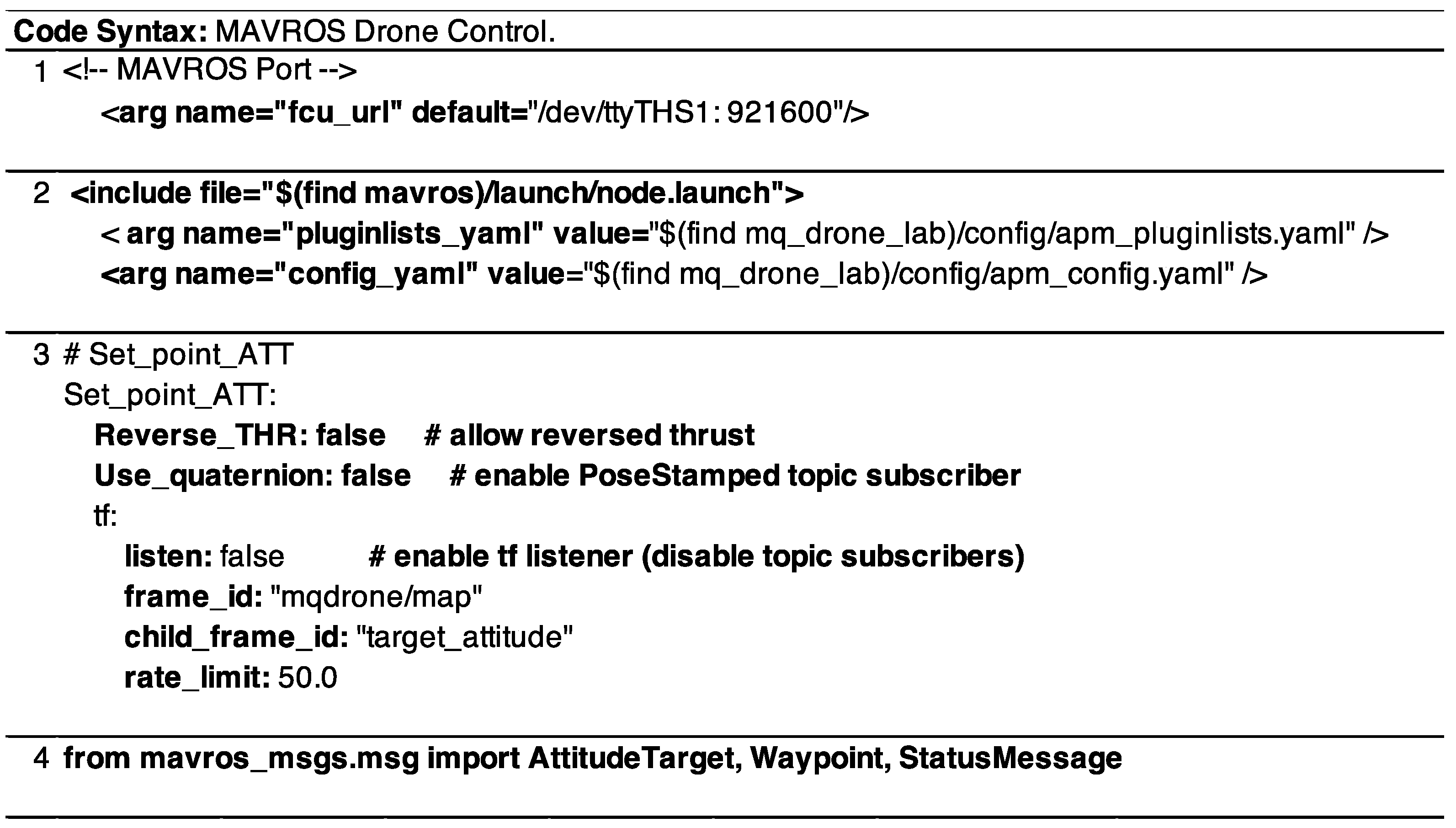
4.4. Drone Controller Software

Figure 7 shows the code snippets for the OBC written in Python for the ROS package installed in the ‘catkin_ws’.
The OBC communicates via the telemetry 2 port of the FC, as discussed earlier. The MAVLINK communication is established using MAVROS. To configure this, the serial baud and protocol must be modified on the FC. In the OBC, the MAVROS port is set up by using the (1) code in Figure 7. Here, the ttyTHS1 is the port that connects with Telemetry 2, and 921600 is the baud rate for communication. The MAVROS package installed in the OBC reads the APM firmware configurations through the (2) section in Figure 7. This connects to the ‘.yaml’ file that provides the state of the application, in this case, the delivery drone. To control the altitude of the flight of the delivery drone using MAVROS, the ROS publisher subscriber transform node is used as seen in (3) of Figure 7. To enable these controls, the MAVROS_MSGS imports the attitude target, waypoints, and status message seen in Figure 7 part (4).

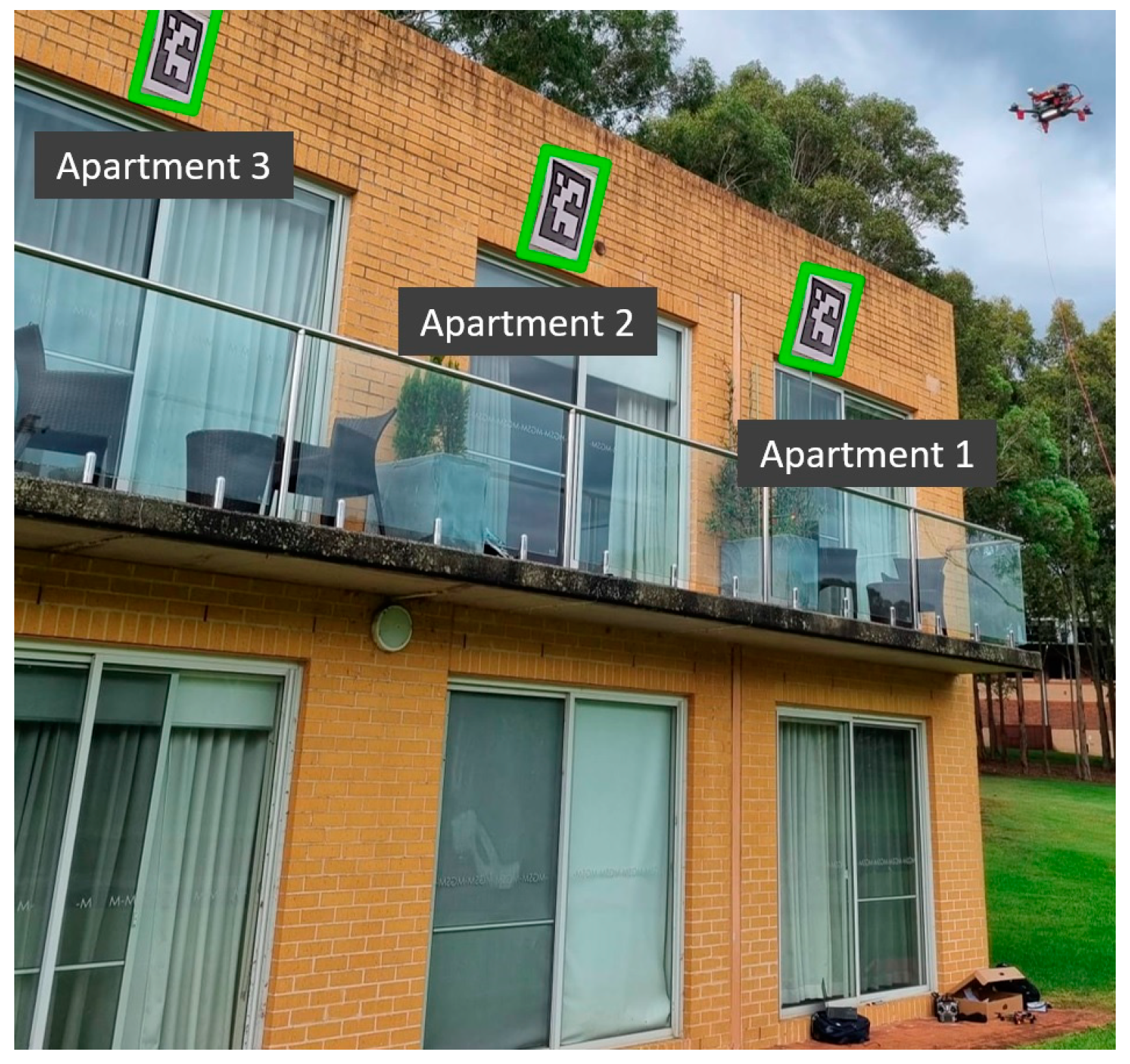
5. Apartment Marker Detection

The drone system uses the YOLOv5 (You Look Only Once) architecture that is capable of detecting objects in real-time and has been pre-trained using the dataset by COCO. In this system, the image is processed using a single neural network. The selected frame of the image is divided into different regions, and the model creates a bounding box for every region while also assigning the confidence of detection. The YOLO models are recognised for precise and quick detection and hence are popular in applications of autonomous vehicles, surveillance and tracking, medical systems, etc.
There are three main components in the YOLOv5 architecture: the ‘backbone’ is the section that extracts the feature; the ’neck’ is the section that aggregates the feature; and the ‘head’ is the section to derive the predictions. The YOLOv5 model uses a unique Cross Stage Partial (CSPDarknet) network. CSPNet essentially truncates the flow of the gradient. It allows for substantial improvement with deeper networks in terms of the processing time for the input image.
The CSPNet stage has two implementations, the partial dense block and the partial transition layer. This backbone network for YOLOv5 sustains the feature reuse characteristics of the DenseNet architecture. However, it excludes the redundant information of the gradient by trimming its flow. The main reason to design the partial transition layer is that it uses the hierarchical feature fusing strategy, thus maximising the gradient combination difference. The given Equation (1) shows the weight updating post the feed-forward output for the dense layer:
ω k = f ( ω k , g 0 , g 1 , g 2 , , g k 1 )
That is followed by the updating of weights in the transition layer in Equation (2)
ω T = f ( ω T , g 0 , g 1 , g 2 , , g k )
The final Equation (3) is the weight updating for the output layer
ω U = f ( ω U , g 0 , g T )
In the above equation, ω k is the weights function for the output of the dense layer; ω T represents the weights function for the transition layer; ω U is the weights function for the output layer.
It can be observed that the gradient of the dense layer is distinctly integrated. In the stages of updating the weights equation, it is observed that the gradient information does not have any duplication on either side making the model very efficient for applications in drone detection.
Three outputs are returned by the YOLOv5 architecture, namely the detected objects classes, the bounding box for the object, and the final output of the scores of the object. The ‘Ultralytics’ that developed the YOLOv5 architecture employs the Binary Cross Entropy (BCE) with Logits Loss Function. Within the ‘PyTorch’ framework, the loss calculation Equation is:
L T o t a l = L c + L o + L l
In Equation (4), the final total loss (LTotal) of the objectness and the various classes is computed. L c is the class loss; L o is the object loss; and Ll is the location loss. While estimating using PyTorch, the loss equations merge the ‘SiLu’ (Sigmoid Linear Unit) function layer and the BCE loss in one single class.
Drone delivery requires prediction of the object bounding box, with a predefined class for marker detection with confidence value. Here, the focus of the performance is mainly analysed using the Mean Average Precision. These are classified into two metrics: mAP0.5 and mAP, which are expressed in the given Equations (5) and (6):
m A P 0.5 = 1 x c l a s s 0 1 P r R l d R
m A P = 1 X c l a s s j = 1 x c l a s s A P r j
In the equation above, xclass is the number of classes; Pr is the Precision value; Rl is the Recall value. Equations (7) and (8) depict the expression for precision and recall, respectively, that are used to compute the mean average precision values:
P r = T P T P + F P
R l = T P T P + F N
The value TP refers to True Positives; FP refers to False Positives; and FN refers to False negatives.

5.1. Model Comparison

The YOLOv5 architecture comprises five varying models that are of different sizes, i.e., nano (YOLOv5n), small (YOLOv5s), medium (YOLOv5m), large (YOLOv5nl), and extra-large (YOLOv5x). The architecture employs a CSPNet architecture along with the SPP (Spatial Pyramid Pooling) layer for the backbone of the YOLOv5 model, as mentioned previously. Given the five architectures of the YOLOv5 model, each of them varies based on the size and input parameters used for the performance and output. The selection of the respective architecture is based on the application and hardware capabilities.
A total of 4000 images of the marker with the apartment information were trained in this dataset using the Roboflow API, wherein the images were primarily augmented. The improvement in training for YOLOv5 is due to the PyTorch training methodologies. The images are augmented to create several transformations to the base data used for training. This creates a wider exposure to the model for images with varying semantic ranges, such as image scaling, colour adjustments, and ‘mosaic’ augmentation, that essentially associates four images as four tiles assigned with a random ratio. Using this input, the training model computes the final loss functions from the objectness and class functions as highlighted earlier. The use of these functions enables the maximisation of the mAP value. Figure 8 highlights the results of the feature extraction training for the YOLOv5s model.
For this experiment, there were a total of four models (nano, small, medium, and large) trained for two batch sizes, i.e., 16 and 32. The above is one of the eight training outcomes that were conducted.
The results highlight the loss functions discussed earlier; the box_loss is the mean squared error for the regression loss of the bounding box; the obj_loss highlights the objectness of the marker, i.e., the confidence the marker being present; and the class_loss is the classification loss to be able to distinguish marker identity. The markers trained belong to a single class; thus, it is observed that there are no misidentifications in class_loss. The values for the precision and recall are computed using the prediction instances of the bounding box, which are True positives and False Positives/Negatives. Table 2 shows the values of the average precision (AP) that is the given area under the P-R (precision and recall) curve.
The AP is an excellent metric for comparing various models. The F1 score aids in determining the confidence threshold. The F1 score is the harmonic mean of the precision and recall values. A well-trained model will show increased precision and decreased recall with the progression of the confidence values. The mAP_0.5 values for the models for four models for the 16 batch were as follows: nano: 0.9630, small: 0.9654, medium: 0.9679, large: 0.9688, and the values for the 32 batch were nano: 0.9678, small: 0.9701, medium: 0.9733, and large: 0.9758. These models were further loaded into the onboard computer to test the speed of detection vs. distance. The desired model is based on the time of detection onboard the drone which is inferred in this subsequent section.

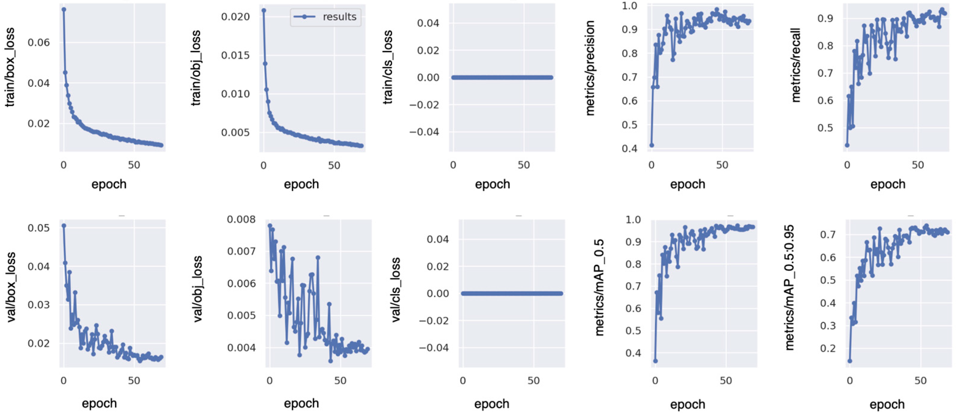
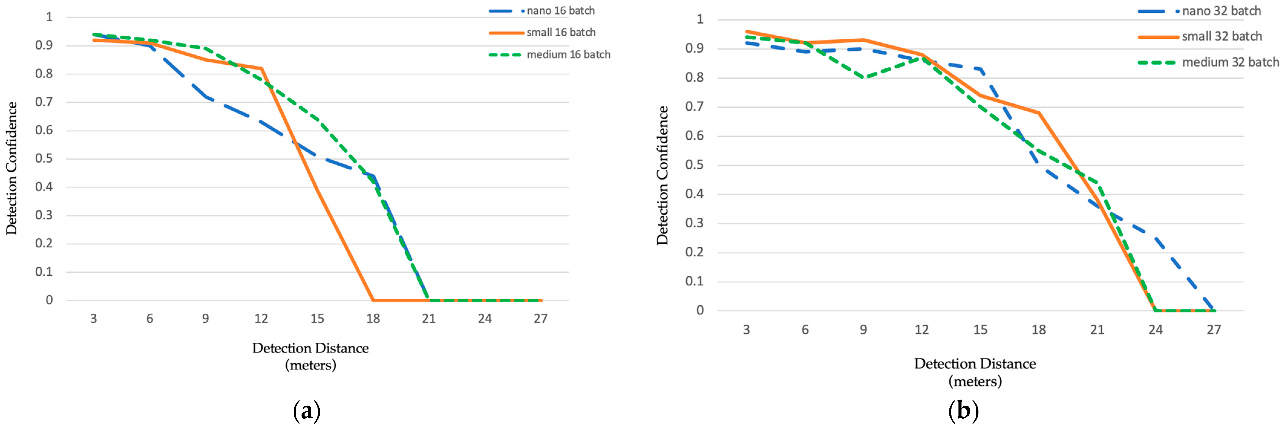
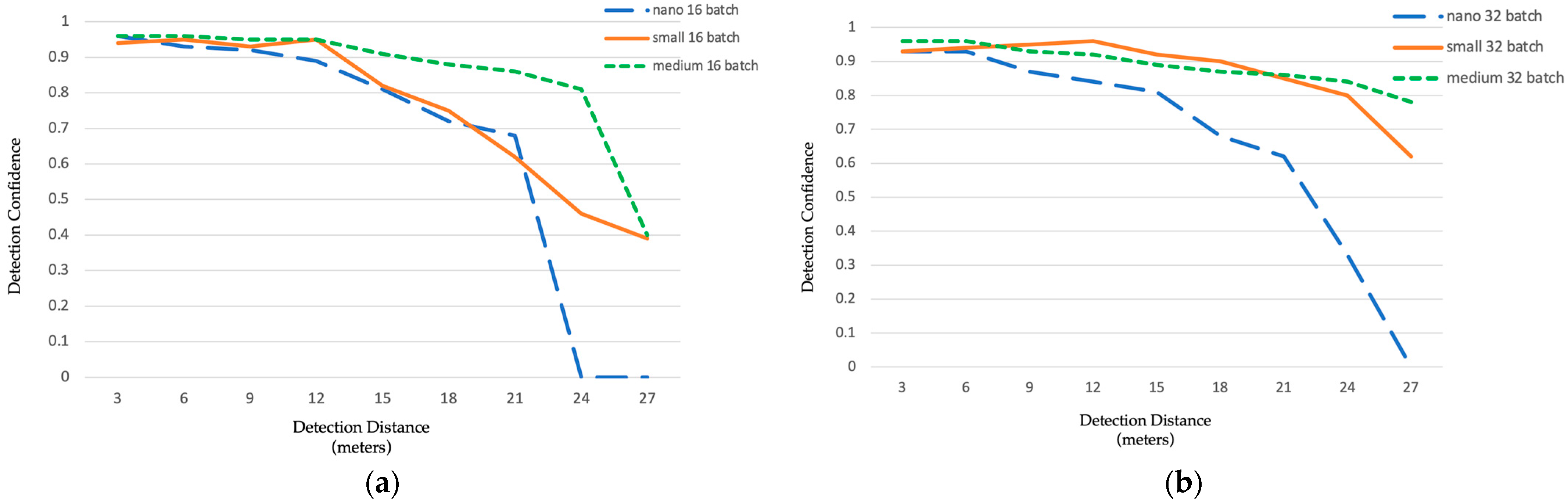
5.2. Marker Detection Performance

The trained YOLOv5 model dataset is loaded on the Jetson Nano board as a ‘.pt’ file format. Firstly, the large model did not load mid-flight on the OBC due to a very high detection lag and therefore was not considered for further comparison. Figure 9 shows the performance metrics of the model (nano, small, and medium) for the detection confidence vs. detection distance performed during outdoor flight test. Figure 9a shows the graph for 16 batch size and Figure 9b for 32 batch size, both having a resolution of 480 × 640 pixels. According to the line graph, the confidence of 32 batches is much higher even at larger distances.
Out of the three training architecture sizes, the nano 32 batch size model showed the maximum confidence at a 24 m distance while operating at only 54 ms processing latency on the Jetson Nano board compared to the 123 ms and 289 ms for the small and medium sizes. This is most suitable for a long-range scanning scenario. Table 3 shows the different time of detection values for the YOLOv5 models for the two resolutions and batch sizes.
Increasing the camera’s resolution size significantly affects the confidence level and distance of detection as seen in Figure 10a,b in a similar experiment performed while changing only the resolution. The resolution increase is a trade-off between the time of detection which ranges from about 171 ms for the nano-sized model to 990 ms for the medium-sized model. Comparing the two figures, it is realized that the small 32 outperforms all the other model sizes detecting markers at 0.96 confidence to 0.80 for the 12 m to 24 m range.
Although the medium 32 has comparatively higher confidence from 21 m to 27 m, the detection time of almost 1 sec can slow down the entire process drastically. Hence, the resolution of 960×1280 pixels with the small 32 models at 389 ms detection time was selected to be the most suitable for the drone delivery application.

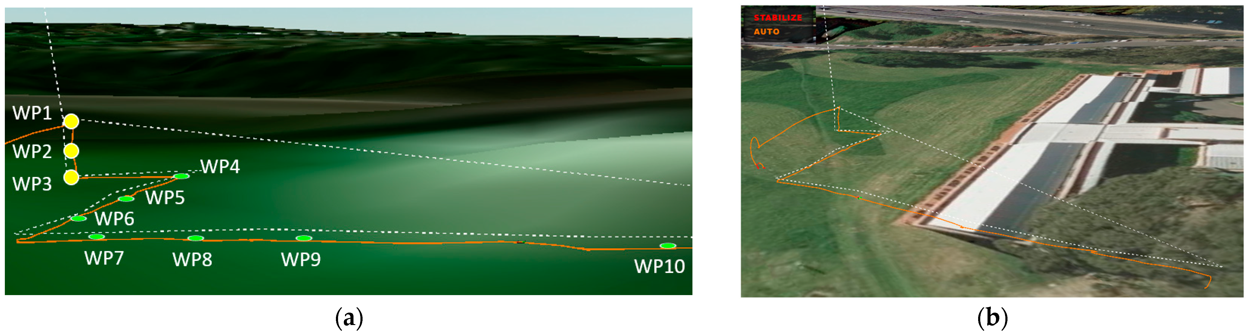
6. Drone Vertical Search Performance

The following section discusses the method of trajectory estimation for apartment deliveries. The experimental test results illustrate the importance of the correlation of trajectory planning with sensor output measurements.

6.1. Formatting of Mathematical Components

The Intel stereoscopic camera’s field of view (FOV) is used to determine a grid for apartment structures to be covered. The designated delivery building will then be divided into the grid size based on the camera onboard the drone. When the drone is at the centre of the grid, it will cover the entire available cell and detect the marker. Figure 11 highlights the drone camera’s field of vision while flying at the designated horizontal distance (d) from the apartment balcony. The drone computes the value of (d) from the onboard front-facing ranging sensor.
To estimate the breadth of the FOV, Equation (9) is used, and Equation (10) computes the height of the FOV from the designated distance d as follows:
b = 2 d [ tan ( φ 2 ) ]
h = 2 d [ tan ( θ 2 ) ]
In the above Equation, b is the breadth of the camera’s Field of View; h is the height of the camera’s Field of View; d is the horizontal distance between the apartment and the drone; φ is the vertical angle of the camera; and θ is the horizontal angle of the camera.
The onboard Intel camera has the θ value of 87° and the φ value of 58°. That computes the FOV to approximately 5 m × 3 m for a 3 m distance between the drone and the apartment. The drone will detect several markers within that range and hover closest to the highest confidence marker box. The FOV estimation optimises selection of waypoints based on the marker information retrieved from the camera. This will allow for quicker detection and save on flight and mission time.

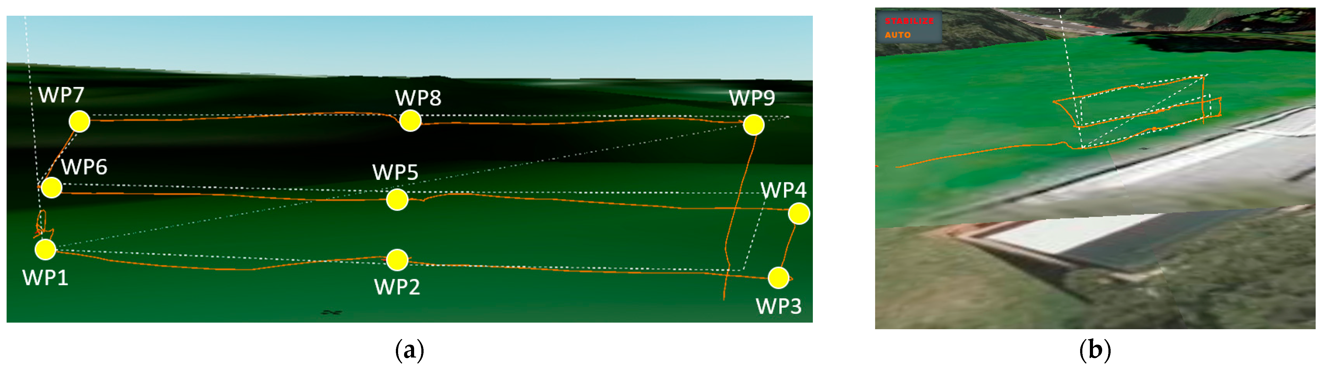
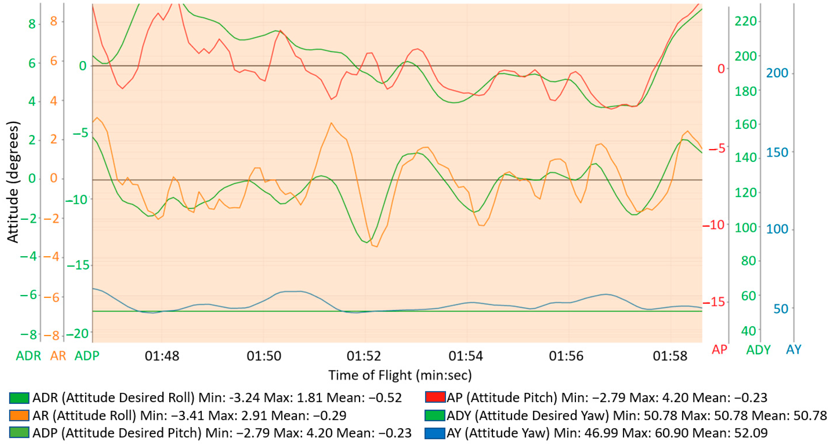
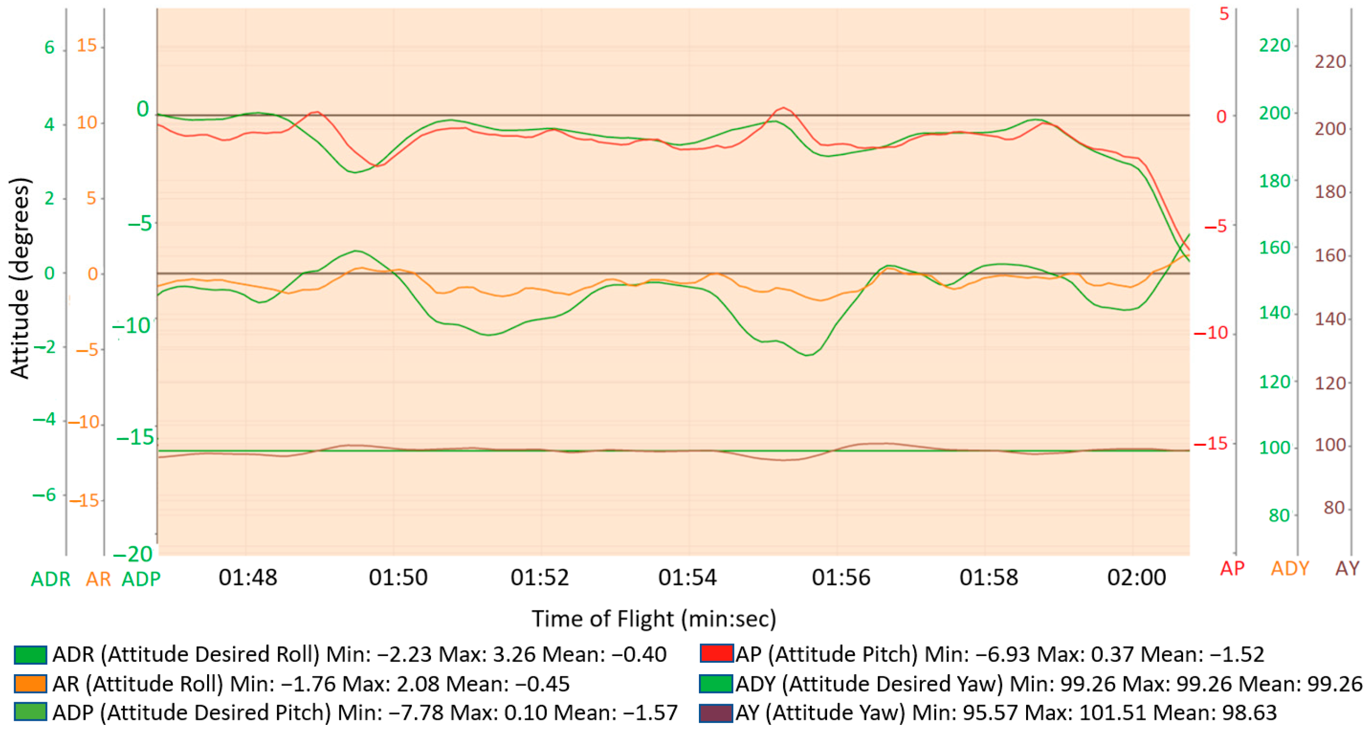
6.2. Outdoor Flight Test Results

The drone flight is controlled using the onboard computer in GUIDED mode. The mission is predefined with the GPS location locked, as discussed previously. The drone’s onboard computer connects to the ADC (Air Drone Control) using Wi-Fi. The camera vision was live-streamed on the ROS network during the preliminary flight tests outdoors. The goal of the test flights is to enable the maximum area coverage for marker detection.
A predefined flight path with waypoints (WP) marking the distance between two apartments was set on the mission planner. The apartments were spaced at a 2.5 m distance with the drone elevating by 3 m every time it reached the final waypoint in one line. Figure 12 shows the VGS flight test data for the Grid Screening pattern. Figure 12a depicts the flight log data from the GPS. The drone can be traced flying across the nine waypoints, and Figure 12b highlights the selected VGS trajectory for the apartment beside the university lake. In the grid scanning, the drone scans the building to check for apartments with a marker. The drone commences the horizontal scan for the first level, as seen in waypoints 1 to 3. The drone moves vertically shown from waypoint 3 to 4 to move to the next level and continues with a horizontal scan of the apartments. The scanning process continues till the apartment for delivery is detected.
A predefined flight path with the implemented VGS algorithm was added to the drone and tested in AUTO mode. Figure 13 shows the VGS flight test data for the Square Screening pattern. Figure 13a depicts the flight log data from the GPS. The drone can be traced flying across the 10 waypoints, and Figure 13b highlights the selected VGS trajectory for the apartment beside the university lake. In the square grid scanning, the first three waypoints (WP) represent the vertical scanning of the building levels. The floor number matches the delivery address; then, the drone commences a horizontal scan in a square pattern, seen in waypoints 4 to 10, to check for the apartment number.
The camera FOV creates an estimated grid-based frame for the drone to search for apartment delivery, as previously explained. The most efficient path to fly for apartment detection is the back-and-forth, wherein the drone will fly horizontally till the end of the line rotate and elevate to the next level way point. Thus, to estimate the time of path completion to scan the apartment can be estimated using Equation (11):
D T = R l D s p d + i = 1 n α i D γ
In Equation (11), DT stands for drone flight completion time; Rl is the length of the route; Dspd is the speed of the drone; n is the number of turns; αi denotes the angle of the ith number of turns; and Dγ is the rotation rate of the drone. The experiments for the grid screening have a drone flight duration of 10.5 s at 2.5 m/s speed. The grid screening had five turns, with the drone rotating 180 degrees for every turn. The total flight duration for the square screening pattern is 9.5 s, with 180-degree drone rotation for every three turns.
Before testing the drone outdoors, the drone’s autonomous functionalities were tested indoors in controlled conditions to ensure safety and precise operation. The autonomous outdoor flight test was performed to scan the marker and detect the appropriate apartment for a two-storey building with multiple apartments in the horizontal direction as shown in Figure 14. The weather conditions were cloudy with wind speeds of about 10 to 15 km/h and 23 °C average temperature. The onboard camera was able to detect markers with 0.92 confidence.
Figure 15 shows the flight data log of the drone’s mid-flight autonomous mission obtained from the FC. It shows the flight test for the Grid Screening test, and Figure 16 shows the Square Screening test results. It highlights the actual vs. desired values for Roll, Pitch, and Yaw. The lines in green represent the desired values of Roll, Pitch, and Yaw, respectively, from the top. According to the graph, there is little variation in Yaw values thus creating an average error rate of about 0.05%. The error rate for roll and pitch is approximately 0.1% proving the drone can maintain its stability and path accurately even with the outdoor environmental conditions.
Figure 17 shows the horizontal ground speed data highlighting the section on drone marker detection and user authentication. The horizontal ground speed varies in different peaks when the drone is performing the VGS scanning algorithm as observed in the graph. Upon detecting the marker, the drone initiates the authentication procedure which is seen at 1 min 47 s to 1 min 59 s of flight.
Thus, according to the observations made for the flight tests outdoors, it was inferred that the drone functions accurately with the VGS algorithm with minimal error rate for the desired and actual Roll, Pitch, and Yaw values. The marker detection at different distances gave promising results using the stereo camera even at comparatively far-off distances.

7. Conclusions

The results presented in this research show a novel autonomous drone delivery technique using Vertical Grid Screening for apartment buildings, which forms grids over the target area to be scanned (in this case, the apartments) using the camera’s FOV (Field of View). Grid-based screening is intended to speed up drone identification. The proposed solution offers an optimal and viable opportunity for using UAVs to deliver parcels in this application. The system consists of a computing board that runs the pre-trained YOLOv5 model for marker detection using a camera. We have also added a security layer of user authentication to avoid any thefts. We compare two training batch sizes, with four different models for different resolutions and test these on the drone’s computing board for detection range and confidence. It was inferred that the YOLOv5s model with 32 batch size at a resolution of 960 × 1280 pixels gave the best performance with a detection time of 389 ms for the 24 m range and about 0.90 confidence value. This shows great potential for using YOLOv5 in detecting markers from far-off distances with very high confidence. Outdoor experiments are performed to verify the performance of the drone delivery algorithm. The results for desired vs. actual values for RPY (Roll, Pitch, and Yaw) show a maximum error rate of 0.1% proving the precision and stability of the drone. A more effective trajectory planning technique based on a VGS pattern is suggested in this study to create the best possible route linking the start node and the destination node for marker identification. With respect to both duration and maximum coverage, the VGS pattern and the chosen control strategy produce the best trajectory.
The potential scalability of the proposed model to handle an increasing volume of deliveries without compromising its efficiency or performance is crucial. All the hardware and software systems used are open-source and development friendly with industry-standard components, e.g., Ardupilot, ROS, Pixhawk, and Jetson Nano board. It is possible to effectively adapt to changes in the type of drones used, demand in the number of orders, software stack, routing algorithms, and other technologies, making it an attractive solution for companies looking to streamline their delivery operations. Acceptance in public attitude towards drone delivery and government regulations would help businesses scale such projects to multiple regions.
For this work, the scope was focused on a custom setup that can be replicated affordably, given the challenges related to testing UAV concepts in outdoor environments close to buildings and people. However, the proposed system can be securely tested using appropriate safety protocols and government guidelines. Additionally, it is advised to use extra safety measures like netted flight test facilities, propeller guards, and UAV motor arming safe checks. Adding collision avoidance sensors and rotor guard protection will help reduce the chances of rotor wings hitting the railings of the balcony. Furthermore, the downwash caused due to rotors flying close to the confined balcony areas can be minimised with a payload release mechanism, using VTOL (Vertical Takeoff and Landing) drones proven to be good for use in confined spaces, and a slow and controlled descent in the final drone delivery stages. Further work aims to enhance the VGS model characterisation and design, improve the detection distance and confidence, and explore the influence of environmental parameters in outdoor testing. Additionally, future work will involve a more robust and faster software architecture using ROS 2.

Author Contributions

Conceptualization, A.S. and E.K.; Methodology, A.S., A.J. and E.K.; Software, A.J.; Validation, E.K.; Formal analysis, A.J., E.K. and S.M.; Investigation, E.K. and R.H.; Resources, S.M. and R.H.; Data curation, A.J., E.K. and R.H.; Writing—original draft, A.S. and A.J.; Writing—review and editing, A.S., A.J., E.K., S.M. and R.H.; Supervision, S.M. and R.H.; Project administration, S.M.; Funding acquisition, R.H. All authors have read and agreed to the published version of the manuscript.

Funding

This research received no external funding.

Data Availability Statement

Data sharing is not applicable.

Acknowledgments

The authors acknowledge the continued support from Macquarie University through the Computing and Engineering Faculty for providing the resources and space required for this research. We also acknowledge the technical staff at Macquarie for providing support and hardware tools required for prototyping.

Conflicts of Interest

The authors declare no conflict of interest.

Abbreviations

The following abbreviations are used in this manuscript:
VGSVertical Grid Screening
GSGrid Screening
SSSquare Screening
YOLOYou Only Look Once (Real-Time Object Detection)
UAVUnmanned Aerial Vehicle
ACTAustralian Capital Territory
TDRATruck Drone Routing Algorithm
MILPMixed Integer Linear Program
GPSGlobal Positioning System
FoVField of View
AIArtificial Intelligence
GAGenetic Algorithm
CPPCoverage Path Planning
ArUcoAugmented Reality University of Cordoba
mAPmean Average Precision
ROSRobot Operating System
FCFlight Controller
RTLReturn to Launch
LiDARLight Detection and Ranging
OBCOnboard Computer
DoFDegree of Freedom
IMUInertial Measurement Unit
BLDCBrushless Direct Current
SSHSecure Shell
USBUniversal Serial Bus
UARTUniversal Asynchronous Receiver-Transmitter serial communication
ESCElectronic Speed Controller
ADCAir Drone control

Appendix A. Additional Information

Table A1. The specifications table with information about the drone system used for testing.
Specifications Drone System
Frame MaterialCarbon Fiber
Frame size295 (width) mm × 295 (length) mm × 55 (height) mm
Propeller size5 inches
Motor (KV)1750
Flight ControllerPixhawk 1 M
TelemetryRadioLink 915 MHz
FirmwareArdupilot 4.3.4
GPSGPS M8N with compass
Max Carrying Load1100 gms
Onboard ComputerNVIDIA Jetson nano
CameraIntel Realsense d455
Ranging SensorTF Mini LiDAR

References

  1. Benarbia, T.; Kyamakya, K. A Literature Review of Drone-Based Package Delivery Logistics Systems and Their Implementation Feasibility. Sustainability 2022, 14, 360. [Google Scholar] [CrossRef]
  2. Tuia, D.; Kellenberger, B.; Beery, S.; Costelloe, B.R.; Zuffi, S.; Risse, B.; Mathis, A.; Mathis, M.W.; van Langevelde, F.; Burghardt, T.; et al. Perspectives in Machine Learning for Wildlife Conservation. Nat. Commun. 2022, 13, 792. [Google Scholar] [CrossRef]
  3. Rejeb, A.; Abdollahi, A.; Rejeb, K.; Treiblmaier, H. Drones in Agriculture: A Review and Bibliometric Analysis. Comput. Electron. Agric. 2022, 198, 107017. [Google Scholar] [CrossRef]
  4. Ho, Y.H.; Tsai, Y.J. Open Collaborative Platform for Multi-Drones to Support Search and Rescue Operations. Drones 2022, 6, 132. [Google Scholar] [CrossRef]
  5. Ahmad, T.; Cavazza, M.; Matsuo, Y.; Prendinger, H. Detecting Human Actions in Drone Images Using YoloV5 and Stochastic Gradient Boosting. Sensors 2022, 22, 7020. [Google Scholar] [CrossRef] [PubMed]
  6. Liao, K.C.; Wu, H.Y.; Wen, H.T. Using Drones for Thermal Imaging Photography and Building 3D Images to Analyze the Defects of Solar Modules. Inventions 2022, 7, 67. [Google Scholar] [CrossRef]
  7. Eskandaripour, H.; Boldsaikhan, E. Last-Mile Drone Delivery: Past, Present, and Future. Drones 2023, 7, 77. [Google Scholar] [CrossRef]
  8. Reed, S.; Campbell, A.M.; Thomas, B.W. The Value of Autonomous Vehicles for Last-Mile Deliveries in Urban Environments. Manag. Sci. 2022, 68, 280–299. [Google Scholar] [CrossRef]
  9. Brunner, G.; Szebedy, B.; Tanner, S.; Wattenhofer, R. The Urban Last Mile Problem: Autonomous Drone Delivery to Your Balcony. In Proceedings of the 2019 International Conference on Unmanned Aircraft Systems, ICUAS 2019, Atlanta, GA, USA, 11–14 June 2019; Institute of Electrical and Electronics Engineers Inc.: Piscataway, NJ, USA, 1 June 2019; pp. 1005–1012. [Google Scholar]
  10. Ackerman, E.; Koziol, M. The blood is here: Zipline’s medical delivery drones are changing the game in Rwanda. IEEE Spectr. 2019, 56, 24–31. [Google Scholar] [CrossRef]
  11. Thornton, S.; Gallasch, G.E. Swarming logistics for tactical last-mile delivery. In Proceedings of the International Conference on Science and Innovation for Land Power, Adelaide, Australia, 4–6 September 2018; Volume 2018. [Google Scholar]
  12. Kellermann, R.; Biehle, T.; Fischer, L. Drones for Parcel and Passenger Transportation: A Literature Review. Transp. Res. Interdiscip. Perspect. 2020, 4, 100088. [Google Scholar] [CrossRef]
  13. Sun, L.; Chen, J.; Li, Q.; Huang, D. Dramatic Uneven Urbanization of Large Cities throughout the World in Recent Decades. Nat. Commun. 2020, 11, 5366. [Google Scholar] [CrossRef] [PubMed]
  14. AlphaBeta Report for Wing, The Potential Impact of Delivery Drones in the Australian Capital Territory. Available online: https://wing.com/en_au/resource-hub/articles/act-report/ (accessed on 9 March 2023).
  15. Chen, K.W.; Xie, M.R.; Chen, Y.M.; Chu, T.T.; Lin, Y.B. DroneTalk: An Internet-of-Things-Based Drone System for Last-Mile Drone Delivery. IEEE Trans. Intell. Transp. Syst. 2022, 23, 15204–15217. [Google Scholar] [CrossRef]
  16. Deutsche Post DHL Group (16 May 2019). DHL Express Launches Its First Regular Fully-Automated and Intelligent Urban Drone Delivery Service. Available online: https://www.dpdhl.com/en/media-relations/press-releases/2019/dhl-launches-its-first-regular-fully-automated-and-intelligent-urban-drone-delivery-service.html (accessed on 23 April 2023).
  17. Cho, S.; Lee, D.; Jung, Y.; Lee, U.; Shim, D.H. Development of a Cooperative Heterogeneous Unmanned System for Delivery Services. J. Inst. Control Robot. Syst. 2014, 20, 1181–1188. [Google Scholar] [CrossRef]
  18. Matternet. Available online: https://mttr.net/ (accessed on 23 April 2023).
  19. Flytrex, Drone Delivery in Panama City. Available online: https://www.youtube.com/watch?v=inu78yhL8ZU (accessed on 23 April 2023).
  20. Aurambout, J.P.; Gkoumas, K.; Ciuffo, B. Last Mile Delivery by Drones: An Estimation of Viable Market Potential and Access to Citizens across European Cities. Eur. Transp. Res. Rev. 2019, 11, 30. [Google Scholar] [CrossRef]
  21. Moshref-Javadi, M.; Hemmati, A.; Winkenbach, M. A Truck and Drones Model for Last-Mile Delivery: A Mathematical Model and Heuristic Approach. Appl. Math. Model. 2020, 80, 290–318. [Google Scholar] [CrossRef]
  22. Di Puglia Pugliese, L.; Guerriero, F. Last-Mile Deliveries by Using Drones and Classical Vehicles. In Mathematics and Statistics; Springer: New York, NY, USA, 2017; Volume 217, pp. 557–565. [Google Scholar]
  23. Di Puglia Pugliese, L.; Macrina, G.; Guerriero, F. Trucks and Drones Cooperation in the Last-Mile Delivery Process. Networks 2021, 78, 371–399. [Google Scholar] [CrossRef]
  24. Curlander, J.C.; Gilboa-Amir, A.; Kisser, L.M.; Koch, R.A.; Welsh, R.D. Multi-Level Fulfilment Center for Unmanned Aerial Vehicles. U.S. Patent 9,777,502, 3 October 2017. [Google Scholar]
  25. Golroudbari, A.A.; Sabour, M.H. Recent Advancements in Deep Learning Applications and Methods for Autonomous Navigation—A Comprehensive Review. arXiv 2023, arXiv:2302.11089. [Google Scholar]
  26. Razzaq, S.; Xydeas, C.; Mahmood, A.; Ahmed, S.; Ratyal, N.I.; Iqbal, J. Efficient Optimization Techniques for Resource Allocation in UAVs Mission Framework. PLoS ONE 2023, 18, e0283923. [Google Scholar] [CrossRef]
  27. Dissanayaka, D.; Wanasinghe, T.R.; De Silva, O.; Jayasiri, A.; Mann, G.K.I. Review of Navigation Methods for UAV-Based Parcel Delivery. IEEE Trans. Autom. Sci. Eng. 2023, 1–15. [Google Scholar] [CrossRef]
  28. Mechali, O.; Xu, L.; Xie, X.; Iqbal, J. Theory and Practice for Autonomous Formation Flight of Quadrotors via Distributed Robust Sliding Mode Control Protocol with Fixed-Time Stability Guarantee. Control Eng. Pract. 2022, 123, 105150. [Google Scholar] [CrossRef]
  29. Rao, B.; Gopi, A.G.; Maione, R. The Societal Impact of Commercial Drones. Technol. Soc. 2016, 45, 83–90. [Google Scholar] [CrossRef]
  30. Yoo, W.; Yu, E.; Jung, J. Drone Delivery: Factors Affecting the Public’s Attitude and Intention to Adopt. Telemat. Inform. 2018, 35, 1687–1700. [Google Scholar] [CrossRef]
  31. Eeshwaroju, S.; Jakkula, P.; Abdellatif, I. An IoT Based Three-Dimensional Dynamic Drone Delivery (3D4) System. In Proceedings of the 2020 IEEE Cloud Summit, Cloud Summit 2020, Harrisburg, PA, USA, 21–22 October 2020; Institute of Electrical and Electronics Engineers Inc.: Piscataway, NJ, USA, 1 October 2020; pp. 119–123. [Google Scholar]
  32. EHang and Yonghui Launched China’s First Flagship Store with Drone Delivery Service. Available online: https://www.ehang.com/news/410.html#:~:text=Join%20Us-,EHang%20and%20Yonghui%20Launched%20China’s%20First%20Flagship%20Store%20with%20Drone,and%20aerial%20drone%20food%20delivery. (accessed on 23 April 2023).
  33. Kannan, S.S.; Min, B.C. Autonomous Drone Delivery to Your Door and Yard. In Proceedings of the 2022 International Conference on Unmanned Aircraft Systems, ICUAS 2022, Dubrovnik, Croatia, 21–24 June 2022; Institute of Electrical and Electronics Engineers Inc.: Piscataway, NJ, USA, 2022; pp. 452–461. [Google Scholar]
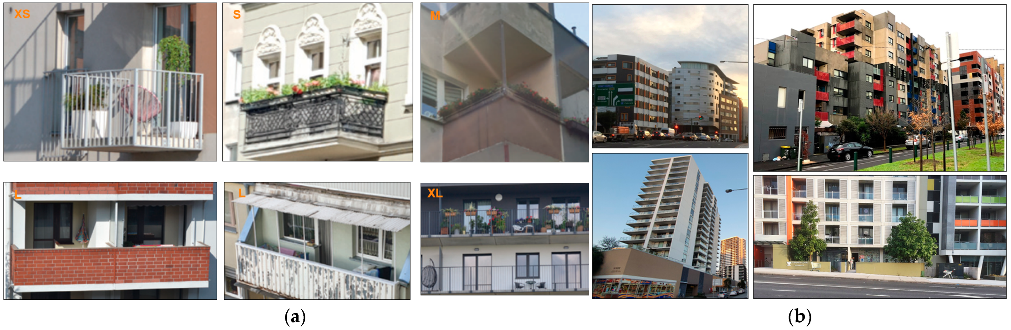
  34. Smektała, M.; Baborska-Narożny, M. The Use of Apartment Balconies: Context, Design and Social Norms. Build Cities 2022, 3, 134–152. [Google Scholar] [CrossRef]
  35. Easthope, H.; Crommelin, L.; Troy, L.; Davison, G.; Nethercote, M.; Foster, S.; van den Nouwelant, R.; Kleeman, A.; Randolph, B.; Horne, R. Improving Outcomes for Apartment Residents and Neighbourhoods; AHURI Final Report; Australian Housing and Urban Research Institute Limited: Melbourne, VIC, Australia, 2020. [Google Scholar] [CrossRef]
  36. Quan, L.; Han, L.; Zhou, B.; Shen, S.; Gao, F. Survey of UAV Motion Planning. IET Cyber-Syst. Robot. 2020, 2, 14–21. [Google Scholar] [CrossRef]
  37. Zhou, H.; Xiong, H.L.; Liu, Y.; Tan, N.D.; Chen, L. Trajectory Planning Algorithm of UAV Based on System Positioning Accuracy Constraints. Electronics 2020, 9, 250. [Google Scholar] [CrossRef]
  38. Nam, L.H.; Huang, L.; Li, X.J.; Xu, J.F. An Approach for Coverage Path Planning for UAVs. In Proceedings of the 2016 IEEE 14th International Workshop on Advanced Motion Control, AMC 2016, Auckland, New Zealand, 22–24 April 2016; Institute of Electrical and Electronics Engineers Inc.: Piscataway, NJ, USA, 20 June 2016; pp. 411–416. [Google Scholar]
  39. Lu, Y.; Xue, Z.; Xia, G.S.; Zhang, L. A Survey on Vision-Based UAV Navigation. Geo-Spat. Inf. Sci. 2018, 21, 21–32. [Google Scholar] [CrossRef]
  40. Chang, C.W.; Lo, L.Y.; Cheung, H.C.; Feng, Y.; Yang, A.S.; Wen, C.Y.; Zhou, W. Proactive Guidance for Accurate UAV Landing on a Dynamic Platform: A Visual–Inertial Approach. Sensors 2022, 22, 404. [Google Scholar] [CrossRef]
  41. Miranda, V.R.F.; Rezende, A.M.C.; Rocha, T.L.; Azpúrua, H.; Pimenta, L.C.A.; Freitas, G.M. Autonomous Navigation System for a Delivery Drone. J. Control Autom. Electr. Syst. 2022, 33, 141–155. [Google Scholar] [CrossRef]
  42. Li, B.; Wang, B.; Tan, X.; Wu, J.; Wei, L. Corner Location and Recognition of Single ArUco Marker under Occlusion Based on YOLO Algorithm. J. Electron. Imaging 2021, 30, 033012. [Google Scholar] [CrossRef]
  43. Nagatomo, M.; Aburada, K.; Okazaki, N.; Park, M. Evaluation of Ad-Hoc Secure Device Pairing Method with Accelerometer and Camera Using Marker. Int. J. Netw. Comput. 2019, 9, 318–338. [Google Scholar] [CrossRef]
  44. Mariusz Kornatowski, P.; Mintchev, S.; Floreano, D. An Origami-Inspired Cargo Drone. In Proceedings of the 2017 IEEE/RSJ International Conference on Intelligent Robots and Systems (IROS), Vancouver, BC, Canada, 4–28 September 2017; ISBN 9781538626825. [Google Scholar]
  45. Ebeid, E.; Skriver, M.; Terkildsen, K.H.; Jensen, K.; Schultz, U.P. A Survey of Open-Source UAV Flight Controllers and Flight Simulators. Microprocess. Microsyst. 2018, 61, 11–20. [Google Scholar] [CrossRef]
  46. Wilson, A.N.; Kumar, A.; Jha, A.; Cenkeramaddi, L.R. Embedded Sensors, Communication Technologies, Computing Platforms and Machine Learning for UAVs: A Review. IEEE Sens. J. 2022, 22, 1807–1826. [Google Scholar] [CrossRef]
  47. Meier, L.; Tanskanen, P.; Fraundorfer, F.; Pollefeys, M. PIXHAWK: A System for Autonomous Flight Using Onboard Computer Vision. In Proceedings of the 2011 IEEE International Conference on Robotics and Automation, Shanghai, China, 9–13 May 2011; pp. 2992–2997. [Google Scholar]
  48. Meier, L.; Honegger, D.; Pollefeys, M. PX4: A Node-Based Multithreaded Open Source Robotics Framework for Deeply Embedded Platforms. In Proceedings of the 2015 IEEE international conference on robotics and automation (ICRA), Seattle, WA, USA, 26–30 May 2015; Institute of Electrical and Electronics Engineers Inc.: Piscataway, NJ, USA, 29 June 2015; Volume 2015, pp. 6235–6240. [Google Scholar]
  49. Delaune, J.; Bayard, D.S.; Brockers, R. Range-Visual-Inertial Odometry: Scale Observability Without Excitation; Range-Visual-Inertial Odometry: Scale Observability Without Excitation. IEEE Robot. Autom. Lett. 2021, 6, 2421–2428. [Google Scholar] [CrossRef]
  50. Stagsted, R.K.; Vitale, A.; Renner, A.; Larsen, L.B.; Christensen, A.L.; Sandamirskaya, Y. Event-Based PID Controller Fully Realized in Neuromorphic Hardware: A One DoF Study. In Proceedings of the 2020 IEEE/RSJ International Conference on Intelligent Robots and Systems (IROS), Las Vegas, NV, USA, 24 October 2020–24 January 2021; Institute of Electrical and Electronics Engineers Inc.: Piscataway, NJ, USA, 24 October 2020; pp. 10939–10944. [Google Scholar]
  51. Benhadhria, S.; Mansouri, M.; Benkhlifa, A.; Gharbi, I.; Jlili, N. VAGADRONE: Intelligent and Fully Automatic Drone Based on Raspberry Pi and Android. Appl. Sci. 2021, 11, 3153. [Google Scholar] [CrossRef]
  52. Braga, R.G.; da Silva, R.C.; Ramos, A.C.B.; Mora-Camino, F. Collision Avoidance Based on Reynolds Rules: A Case Study Using Quadrotors. In Advances in Intelligent Systems and Computing; Springer: Berlin/Heidelberg, Germany, 2018; Volume 558, pp. 773–780. [Google Scholar]
Figure 1. (a) Photographs of different high-rise apartment balcony sizes [34] (b) Photographs of different apartments in Australia [35].
Drones 07 00300 g001
Figure 2. (a) The Grid Screening method; (b) The Square Screening method.
Drones 07 00300 g002
Figure 3. The flowchart of the proposed delivery for apartments with balconies.
Drones 07 00300 g003
Figure 4. The steps of IoT User Authentication for the drone delivery completion.
Drones 07 00300 g004
Figure 5. The photograph of the drone system assembled and ready for testing: (a) the top view of the assembled drone; (b) the front view highlighting the stereo camera used for marker detection; (c) the QR code with apartment information.
Drones 07 00300 g005
Figure 6. The block diagram to implement the marker detection for the drone system.
Drones 07 00300 g006
Figure 7. The code snippets for the OBC control of the drone.
Drones 07 00300 g007
Figure 8. Mean Average precision and validation loss training result for four different 32-batch YOLOV5S models for approximately 4000 augmented images.
Drones 07 00300 g008
Figure 9. The following graphs illustrate the comparison results between three YOLOV5 (nano, small, and medium) models tested on the OBC of the drone system: (a) Confidence vs. Distance for 16 batch size model using 480 × 640 pixels image resolution; (b) Confidence vs. Distance for 32 batch size model using 480 × 640 pixels image resolution.
Drones 07 00300 g009
Figure 10. The following graphs illustrate the comparison results between three YOLOV5 (nano, small, and medium) models tested on the OBC of the drone system: (a) Confidence vs. Distance for 16 batch size models using 960 × 1280 pixels image resolution. (b) Confidence vs. Distance for 32 batch size model using 960 × 1280 pixels image resolution.
Drones 07 00300 g010
Figure 11. The drone camera’s field of vision.
Drones 07 00300 g011
Figure 12. VGS Flight Test for Grid Screening (a) The GPS flight log illustrating the trajectory (orange line) of the flight and waypoints (in yellow) to scan apartments in a row. (b) The front view of the flight log in AUTO mode illustrates the executed trajectory.
Drones 07 00300 g012
Figure 13. VGS Flight Test for Square Screening (a) The GPS flight log illustrating the trajectory of the flight (orange line) and waypoints (highlighted in yellow to scan for floor numbers and highlighted in green to scan apartments in a row). (b) The front view of the flight log in AUTO mode illustrates the executed trajectory.
Drones 07 00300 g013
Figure 14. The autonomous flight test near a building to scan the marker and detect the correct delivery apartment.
Drones 07 00300 g014
Figure 15. The flight log data of the drone mid-flight highlighting the actual vs. desired Roll, Pitch, and Yaw values for the Grid Screening Pattern test.
Drones 07 00300 g015
Figure 16. The flight log data of the drone mid-flight highlighting the actual vs. desired Roll, Pitch, and Yaw values for the Square Screening Pattern test.
Drones 07 00300 g016
Figure 17. The horizontal ground speed data highlighting the section on drone marker detection and user authentication.
Drones 07 00300 g017
Table 1. The feature comparison between the proposed OBCs.
Feature NVIDIA Jetson NanoRaspberry Pi 4B
CPU ARM Cortex-A57 (64 bit) ARM Cortex-A72 (64 bit)
GPU and Cores Maxwell with CUDA with 128 Cores Video Core VI 3D (0 Cores)
Memory 4 GB LPDDR4 4 GB LPDDR4
Storage Micro SD (8 GB to 1 TB) Micro SD or 16 GB eMMC
Power Requirements (Under Load) 2.56 W–7.30 W (620 mA to 1430 mA) 10 W to 20 W (3 A to 6 A)
Wireless Connectivity None Wi-Fi and Bluetooth
Board Dimensions 100 × 79 mm 65 × 56 mm
Table 2. The Average Precision (AP) and F1 score for the YOLOv5 models for the two batch sizes.
Yolov516 Batch Size32 Batch Size
ModelsAvg. PrecisionF1 ScoreAvg. PrecisionF1 Score
Nano0.7980.820.850.872
Small0.9050.910.9160.923
Medium0.920.9290.9350.94
Table 3. The different time of detection values for the YOLOv5 models for the two resolutions and batch sizes.
Yolov5
Models
Time of Detection (ms) 480 × 640 Pixel ResolutionTime of Detection (ms) 960 × 1280 Pixel Resolution
16 Batch Size32 Batch Size 16 Batch Size16 Batch Size
Nano5354171173
Small122123400389
Medium287289989995
Disclaimer/Publisher’s Note: The statements, opinions and data contained in all publications are solely those of the individual author(s) and contributor(s) and not of MDPI and/or the editor(s). MDPI and/or the editor(s) disclaim responsibility for any injury to people or property resulting from any ideas, methods, instructions or products referred to in the content.

